JP2005073744A - Fastener attaching method - Google Patents
Fastener attaching method Download PDFInfo
- Publication number
- JP2005073744A JP2005073744A JP2003304653A JP2003304653A JP2005073744A JP 2005073744 A JP2005073744 A JP 2005073744A JP 2003304653 A JP2003304653 A JP 2003304653A JP 2003304653 A JP2003304653 A JP 2003304653A JP 2005073744 A JP2005073744 A JP 2005073744A
- Authority
- JP
- Japan
- Prior art keywords
- fastener
- base material
- back surface
- mounting base
- tape portions
- Prior art date
- Legal status (The legal status is an assumption and is not a legal conclusion. Google has not performed a legal analysis and makes no representation as to the accuracy of the status listed.)
- Pending
Links
- 238000000034 method Methods 0.000 title claims abstract description 32
- 239000000463 material Substances 0.000 claims abstract description 64
- 229920005989 resin Polymers 0.000 claims abstract description 19
- 239000011347 resin Substances 0.000 claims abstract description 19
- 238000003698 laser cutting Methods 0.000 claims abstract description 11
- 238000003466 welding Methods 0.000 claims abstract description 11
- 210000004513 dentition Anatomy 0.000 claims description 16
- 230000036346 tooth eruption Effects 0.000 claims description 16
- 239000012943 hotmelt Substances 0.000 abstract description 16
- 238000010438 heat treatment Methods 0.000 abstract description 2
- 238000005520 cutting process Methods 0.000 abstract 1
- 239000000853 adhesive Substances 0.000 description 10
- 230000001070 adhesive effect Effects 0.000 description 10
- 239000000758 substrate Substances 0.000 description 9
- 230000000694 effects Effects 0.000 description 7
- 239000004744 fabric Substances 0.000 description 5
- 239000010985 leather Substances 0.000 description 4
- 238000009958 sewing Methods 0.000 description 3
- 229920001169 thermoplastic Polymers 0.000 description 3
- 239000004416 thermosoftening plastic Substances 0.000 description 3
- CURLTUGMZLYLDI-UHFFFAOYSA-N Carbon dioxide Chemical compound O=C=O CURLTUGMZLYLDI-UHFFFAOYSA-N 0.000 description 2
- XEEYBQQBJWHFJM-UHFFFAOYSA-N Iron Chemical compound [Fe] XEEYBQQBJWHFJM-UHFFFAOYSA-N 0.000 description 2
- 239000004020 conductor Substances 0.000 description 2
- 238000002788 crimping Methods 0.000 description 2
- 238000010586 diagram Methods 0.000 description 2
- 239000005038 ethylene vinyl acetate Substances 0.000 description 2
- 238000002844 melting Methods 0.000 description 2
- 230000008018 melting Effects 0.000 description 2
- 229920001200 poly(ethylene-vinyl acetate) Polymers 0.000 description 2
- 229910001369 Brass Inorganic materials 0.000 description 1
- JOYRKODLDBILNP-UHFFFAOYSA-N Ethyl urethane Chemical compound CCOC(N)=O JOYRKODLDBILNP-UHFFFAOYSA-N 0.000 description 1
- 239000010951 brass Substances 0.000 description 1
- 229910002092 carbon dioxide Inorganic materials 0.000 description 1
- 239000001569 carbon dioxide Substances 0.000 description 1
- 230000000052 comparative effect Effects 0.000 description 1
- 238000007796 conventional method Methods 0.000 description 1
- 239000011810 insulating material Substances 0.000 description 1
- 229910052742 iron Inorganic materials 0.000 description 1
- 230000001678 irradiating effect Effects 0.000 description 1
- 230000010355 oscillation Effects 0.000 description 1
- 229920005992 thermoplastic resin Polymers 0.000 description 1
- XLYOFNOQVPJJNP-UHFFFAOYSA-N water Substances O XLYOFNOQVPJJNP-UHFFFAOYSA-N 0.000 description 1
Images
Landscapes
- Slide Fasteners (AREA)
Abstract
Description
本発明は、左右テープ部分の内縁部分に務歯列を設けるとともに前記務歯列を開閉するスライダーを設けて構成したファスナーを、例えば、スキーウェアなどの衣服やバッグなどのファスナー取付基材に無縫製で取り付けるファスナーの取付方法に関する。 According to the present invention, there is provided, for example, a fastener that is provided with a dentition on the inner edge portion of the left and right tape portions and a slider that opens and closes the dentition on a fastener attachment base material such as clothes such as ski wear and a bag. The present invention relates to a method of attaching a fastener attached by sewing.
ファスナーを無縫製で取り付ける方法としては、左右テープ部分の内縁部分に務歯列を設け、その務歯列を開閉するスライダーを設けてファスナー(ファスナー本体)を構成し、左右テープの表面に、左右テープの長手方向に沿って連続するように、予め溶融させておいた熱可塑性の接着体を塗布して被着し、バッグなどの開口部の開口縁と左右テープとの間に接着体を挟むようにして高周波をかけ、接着体を溶融して開口縁と左右テープとを接着させ、開口部にファスナーを取り付けるように構成したものがあった(例えば、特許文献1参照)。
しかしながら、従来方法では、ファスナーの左右テープに予め溶融させた熱可塑性の接着体を被着させるものであり、接着体の被着に手間がかかり、ファスナーが高価にならざるを得ず、その結果としてファスナーを取り付けた商品が高価になる欠点があった。また、ファスナー自体に予め熱可塑性の接着体が被着されているため、ファスナー取付基材の材質によっては、接着体の材質とのなじみが悪く、接着強度が低下する欠点があった。 However, in the conventional method, a thermoplastic adhesive that has been previously melted is attached to the right and left tapes of the fastener, and it takes time to attach the adhesive, and the fastener must be expensive. As a result, there was a drawback that the product attached with the fastener was expensive. Moreover, since the thermoplastic adhesive body was previously attached to the fastener itself, depending on the material of the fastener mounting base material, there was a problem that the familiarity with the material of the adhesive body was poor and the adhesive strength was lowered.
また、従来一般に、ファスナー取付基材側において、ファスナーを取り付ける開口部を形成するのに、カッターなどによって機械的に切断しており、ファスナー取付基材が布製や皮製などの場合に、開口縁と左右テープとを接着体によって接着させていても、その開口縁の切断面に起因してほつれを生じやすく、商品の寿命が短くなる欠点があった。 Further, generally, on the side of the fastener mounting base material, the opening for attaching the fastener is mechanically cut by a cutter or the like, and the opening edge is used when the fastener mounting base material is made of cloth or leather. Even if the left and right tapes are bonded to each other by an adhesive, there is a drawback that fraying is likely to occur due to the cut surface of the opening edge and the life of the product is shortened.
本発明は、上記の点に鑑みてなされたものであって、請求項1に係る発明は、ほつれを生じることなくファスナーをファスナー取付基材に良好に取り付けて品質を向上できるようにすることを目的とし、請求項2に係る発明は、ファスナー取付基材の表面を平滑にして製品の高級化を図ることができるようにすることを目的とする。
This invention is made in view of said point, Comprising: The invention which concerns on
請求項1に係る発明は、上述のような目的を達成するために、
左右テープ部分の内縁部分に務歯列を設けるとともに前記務歯列を開閉するスライダーを設けて構成したファスナーをファスナー取付基材に取り付けるファスナーの取付方法であって、
前記ファスナー取付基材の裏面または表面に、離型紙を付設したホットメルト樹脂を接着し、その後に、前記左右テープ部分との重ね合わせ部分を残す状態で前記務歯列およびスライダーを嵌入可能な空間を形成するように前記ファスナー取付基材をレーザ切断機により切抜き、前記ファスナー取付基材の裏面または表面から前記離型紙を剥がしてから前記左右テープ部分を前記ファスナー取付基材の裏面または表面に加熱状態で圧着し、しかる後に、高周波溶着により前記左右テープ部分を前記ファスナー取付基材の裏面または表面に一体的に接着することを特徴としている。
In order to achieve the above-described object, the invention according to
A fastener mounting method for mounting a fastener that is provided with a slider for opening and closing the service tooth row on the inner edge portion of the left and right tape portions and attaching the fastener to a fastener mounting base material,
A space in which the hot tooth resin with release paper attached is adhered to the back surface or the front surface of the fastener mounting base material, and then the dentition and the slider can be fitted in a state where an overlapping portion with the left and right tape portions remains. The fastener mounting base material is cut out by a laser cutting machine so as to form a sheet, and the release paper is peeled off from the back surface or the front surface of the fastener mounting base material, and then the left and right tape portions are heated to the back surface or the front surface of the fastener mounting base material. The right and left tape portions are integrally bonded to the back surface or the surface of the fastener mounting base material by high-frequency welding.
(作用・効果)
請求項1に係る発明のファスナーの取付方法の構成によれば、離型紙を付設したホットメルト樹脂を接着した後に、ファスナー取付基材をレーザ切断機により切抜き、ホットメルト樹脂を介しての高周波溶着により、ファスナーの左右テープをファスナー取付基材に一体的に接着する。
(Action / Effect)
According to the configuration of the fastener attachment method of the invention according to
したがって、ファスナー取付基材をレーザ切断機によって局部的に加熱しながら切抜くから、切断面が溶着した状態となり、布製のものはもちろんのこと皮製のものでも切断面からほつれを生じることを回避できる。 Therefore, the fastener mounting base material is cut out while being locally heated by a laser cutting machine, so that the cut surface is in a welded state, and it is possible to avoid fraying from the cut surface, not only of cloth but also of leather. it can.
しかも、ファスナー取付基材に離型紙を付設したホットメルト樹脂を接着するから、ファスナー取付基材の材質に適したものを容易に選んで接着し、そのホットメルト樹脂を介しての高周波溶着により、ファスナーの左右テープをファスナー取付基材に一体的に接着するから、左右テープとファスナー取付基材との密着性を向上でき、無縫製によって製作性を向上できるのみならず、その接着箇所の止水効果を高くでき、製品の品質を向上できる。特に、スキーウェアなどに適用する場合などにおいて有用である。 Moreover, since the hot melt resin with release paper attached to the fastener mounting base material is bonded, it is possible to easily select and bond a suitable material for the fastener mounting base material, and by high frequency welding through the hot melt resin, Since the left and right tapes of the fastener are integrally bonded to the fastener mounting base material, the adhesion between the left and right tapes and the fastener mounting base material can be improved. The effect can be enhanced and the quality of the product can be improved. This is particularly useful when applied to ski wear and the like.
また、請求項2に係る発明は、前述のような目的を達成するために、
請求項1に記載のファスナーの取付方法において、
左右テープ部分によって務歯列が左右テープ部分の表面側に露出しないようにファスナー取付基材の裏面に前記左右テープ部分を接着して構成する。
In order to achieve the above-described object, the invention according to
In the attachment method of the fastener according to
The left and right tape portions are bonded to the back surface of the fastener mounting base so that the dentition row is not exposed to the front surface side of the left and right tape portions by the left and right tape portions.
(作用・効果)
請求項2に係る発明のファスナーの取付方法の構成によれば、務歯列を左右テープの裏面側に位置させ、ファスナー取付基材の表面側にはスライダーが露出する状態でファスナーをファスナー取付基材にとりつけることができる。
(Action / Effect)
According to the configuration of the fastener mounting method of the invention according to
したがって、ファスナー取付基材の表面全体を、務歯列に触れない滑らかな状態にできるとともに止水効果を高くできるから、スキーウェアなどに適用した場合に製品の高級化を図ることができる。 Therefore, the entire surface of the fastener mounting base material can be brought into a smooth state without touching the dentition and the water-stopping effect can be enhanced, so that the product can be upgraded when applied to ski wear.
請求項1に係る発明のファスナーの取付方法の構成によれば、ファスナー取付基材をレーザ切断機によって局部的に加熱しながら切抜くから、切断面が溶着した状態となり、布製のものはもちろんのこと皮製のものでも切断面からほつれを生じることを回避できる。
According to the configuration of the fastener attachment method of the invention according to
しかも、ファスナー取付基材に離型紙を付設したホットメルト樹脂を接着するから、ファスナー取付基材の材質に適したものを容易に選んで接着し、そのホットメルト樹脂を介しての高周波溶着により、ファスナーの左右テープをファスナー取付基材に一体的に接着するから、左右テープとファスナー取付基材との密着性を向上でき、無縫製によって製作性を向上できるのみならず、その接着箇所の止水効果を高くでき、製品の品質を向上できる。特に、スキーウェアなどに適用する場合などにおいて有用である。 Moreover, since the hot melt resin with release paper attached to the fastener mounting base material is bonded, it is possible to easily select and bond a suitable material for the fastener mounting base material, and by high frequency welding through the hot melt resin, Since the left and right tapes of the fastener are integrally bonded to the fastener mounting base material, the adhesion between the left and right tapes and the fastener mounting base material can be improved. The effect can be enhanced and the quality of the product can be improved. This is particularly useful when applied to ski wear and the like.
次に、この発明の実施例について図面を参照しながら説明する。 Next, embodiments of the present invention will be described with reference to the drawings.
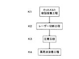
図1は、本発明のファスナーの取付方法の実施例を示す工程図であり、この工程図に基づいて各工程ごとに順に説明する。 FIG. 1 is a process diagram showing an embodiment of the fastener attaching method of the present invention, and each process will be described in order based on this process diagram.
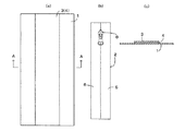
(1)ホットメルト樹脂接着工程K1
図2の(a)の平面図に示すように、布製のファスナー取付基材1の裏面に、図2の(b)の平面図に示すファスナー2の大きさよりやや大きい範囲にわたって、図2の(c)の断面図[図2の(a)のA−A線断面図]に示す、離型紙3を付設したホットメルト樹脂4を接着する。図2の(c)では、ファスナー取付基材1、離型紙3およびホットメルト樹脂4それぞれの厚みは誇張して示している。
(1) Hot melt resin bonding process K1
As shown in the plan view of FIG. 2A, on the back surface of the fabric fastener
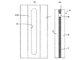
(2)レーザー切断工程K2
図3の(a)の平面図に示すように、ファスナー取付基材1のホットメルト樹脂4を接着した箇所に対して、所定の大きさの開口5が形成されるように、レーザー切断機(図示せず)により切抜く。開口5の大きさは、図3の(b)の平面図に示すように、左右テープ6部分との重ね合わせ部分を残す状態で、ファスナー2を構成する左右テープ6部分の内縁部分に設けた務歯列7と、務歯列7を開閉するスライダー8とを嵌入可能な空間を形成する大きさに設定される。
(2) Laser cutting process K2
As shown in the plan view of FIG. 3 (a), a laser cutting machine (such as a laser cutting machine) is formed so that an opening 5 of a predetermined size is formed at a location where the
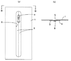
(3)圧着工程K3
図4の(a)の平面図、および、図4の(b)[図4の(a)の一部省略B−B線矢視図]に示すように、ファスナー取付基材1の裏面から離型紙3を剥がしてから左右テープ6部分に重ね合わせ、その状態で、例えば、アイロンなどにより、ファスナー取付基材1の裏面に左右テープ6部分を加熱状態で圧着し、ファスナー取付基材1とファスナー2とを仮止めする。図4の(b)においては、ホットメルト樹脂4を省略している。
(3) Crimping process K3
As shown in the plan view of FIG. 4A and FIG. 4B [partially omitted BB line view of FIG. 4A], from the back surface of the
(4)高周波溶着工程K4
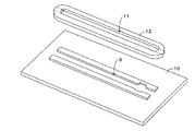
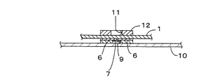
図5の一部展開斜視図、および、図6のファスナーの取付状態の断面図に示すように、ファスナー2の務歯列7とスライダー8の裏側部分を嵌入する凹部9を形成したベークライト製などの絶縁性材料による支持板10上にファスナー取付基材1を載置支持させる。
(4) High frequency welding process K4
As shown in the partially developed perspective view of FIG. 5 and the sectional view of the fastener attached state of FIG. The
更に、ファスナー取付基材1に形成した開口5に対応する開口11を形成した真鍮製などの導電材12をファスナー取付基材1上に載置し、絶縁板10と導電材12とによって左右テープ6部分を挟持し、その状態で、高周波溶着機(図示せず)により高周波をかけ、ホットメルト樹脂4を溶融して左右テープ部分6およびファスナー取付基材1に浸透させる状態で加熱溶着し、左右テープ部分6をファスナー取付基材1の裏面に一体的に接着し、ファスナー取付基材1にファスナー2を取り付ける。
Further, a
比較例として、上述ファスナー取付基材1の切断において、高周波加熱による切断を行ったところ、その切断面にほつれが発生した。これに対して、本発明方法によってファスナー2を取り付けた場合、ファスナー取付基材1の切断面からほつれを生じなかった。これらのことから、本発明により、左右テープ6とファスナー取付基材1との密着性を向上でき、無縫製によって製作性を向上できるのみならず、その接着箇所の止水効果を高くでき、製品の品質を向上できることが明らかであった。
As a comparative example, when the above-described fastener mounting
ファスナー2が、左右テープ部分6によって務歯列7が左右テープ6部分の表面側に露出しないように構成され、かつ、務歯列7がファスナー取付基材1の裏面側に位置するようにファスナー取付基材1にファスナー2が取り付けられ、ファスナー取付基材1の表面全体が、務歯列に触れない滑らかな状態になるように構成されている。
The
上記実施例において使用するホットメルト樹脂4としては、例えば、厚みが70μmで溶融温度(メルティングポイント)が120℃程度のウレタン系熱可塑性樹脂が用いられるが、例えば、エチレン酢酸ビニル共重合体(EVA)など、ファスナー取付基材1の材質に応じ、それぞれに適した性状のものを用いれば良い。
As the
また、上記実施例におけるレーザー切断機で用いるレーザーとしては、炭酸ガス(CO2)レーザーやYAGレーザーなど各種のレーザーが適用できる。また、レーザーを照射するヘッド部は、マイクロコンピュータで制御され、設計通りの軌跡を移動して切断できるように構成されている。また、高周波溶着機の発振周波数としては、一例を示せば、40〜42MHz程度である。 In addition, various lasers such as a carbon dioxide (CO 2 ) laser and a YAG laser can be applied as the laser used in the laser cutting machine in the above embodiment. Further, the head unit for irradiating the laser is controlled by a microcomputer, and is configured so that it can be cut by moving the locus as designed. Moreover, as an oscillation frequency of a high frequency welding machine, if an example is shown, it will be about 40-42 MHz.
また、上記実施例では、布製のファスナー取付基材1にファスナー2を取り付けているが、本発明としては、皮製などのファスナー取付基材1にファスナー2を取り付ける場合にも適用できる。
Moreover, in the said Example, although the
また、上記実施例では、ファスナー取付基材1の裏面に左右テープ6を接着しているが、本発明としては、ファスナー取付基材1の表面に左右テープ6を接着する場合にも適用できる。
Moreover, in the said Example, although the left-
また、上記実施例では、ファスナー2を、左右テープ部分6によって務歯列7が左右テープ6部分の表面側に露出しないように構成し、ファスナー取付基材1の表面を滑らかな状態にできるとともに止水効果を高くできるているが、請求項1に係る発明としては、務歯列7が露出ファスナー取付基材1の表面側に露出するものでも良い。
Moreover, in the said Example, while the
本発明は、衣服やそのポケットとかバッグなどの開閉箇所に使用するファスナーの取り付けに適用できる。 The present invention can be applied to attachment of fasteners used for opening and closing locations such as clothes and pockets or bags thereof.
1…ファスナー取付基材
2…ファスナー
3…離型紙
4…ホットメルト樹脂
6…左右テープ
7…務歯列
8…スライダー
DESCRIPTION OF
Claims (2)
前記ファスナー取付基材の裏面または表面に、離型紙を付設したホットメルト樹脂を接着し、その後に、前記左右テープ部分との重ね合わせ部分を残す状態で前記務歯列およびスライダーを嵌入可能な空間を形成するように前記ファスナー取付基材をレーザ切断機により切抜き、前記ファスナー取付基材の裏面または表面から前記離型紙を剥がしてから前記左右テープ部分を前記ファスナー取付基材の裏面または表面に加熱状態で圧着し、しかる後に、高周波溶着により前記左右テープ部分を前記ファスナー取付基材の裏面または表面に一体的に接着することを特徴とするファスナーの取付方法。 A fastener mounting method for mounting a fastener that is provided with a slider for opening and closing the service tooth row on the inner edge portion of the left and right tape portions and attaching the fastener to a fastener mounting base material,
A space in which the hot tooth resin with release paper attached is adhered to the back surface or the front surface of the fastener mounting base material, and then the dentition and the slider can be fitted in a state where an overlapping portion with the left and right tape portions remains. The fastener mounting base material is cut out by a laser cutting machine so as to form a sheet, and the release paper is peeled off from the back surface or the front surface of the fastener mounting base material, and then the left and right tape portions are heated to the back surface or the front surface of the fastener mounting base material. A method of attaching a fastener, wherein the right and left tape portions are integrally bonded to the back surface or the surface of the fastener attachment base material by high frequency welding.
左右テープ部分によって務歯列が左右テープ部分の表面側に露出しないようにファスナー取付基材の裏面に前記左右テープ部分を接着してあるファスナーの取付方法。
In the attachment method of the fastener according to claim 1,
A fastener attachment method in which the left and right tape portions are bonded to the back surface of the fastener attachment base so that the dentition row is not exposed to the front surface side of the left and right tape portions by the left and right tape portions.
Priority Applications (1)
| Application Number | Priority Date | Filing Date | Title |
|---|---|---|---|
| JP2003304653A JP2005073744A (en) | 2003-08-28 | 2003-08-28 | Fastener attaching method |
Applications Claiming Priority (1)
| Application Number | Priority Date | Filing Date | Title |
|---|---|---|---|
| JP2003304653A JP2005073744A (en) | 2003-08-28 | 2003-08-28 | Fastener attaching method |
Publications (1)
| Publication Number | Publication Date |
|---|---|
| JP2005073744A true JP2005073744A (en) | 2005-03-24 |
Family
ID=34408291
Family Applications (1)
| Application Number | Title | Priority Date | Filing Date |
|---|---|---|---|
| JP2003304653A Pending JP2005073744A (en) | 2003-08-28 | 2003-08-28 | Fastener attaching method |
Country Status (1)
| Country | Link |
|---|---|
| JP (1) | JP2005073744A (en) |
Cited By (2)
| Publication number | Priority date | Publication date | Assignee | Title |
|---|---|---|---|---|
| JP2010125769A (en) * | 2008-11-28 | 2010-06-10 | Pentel Corp | Shaft cylinder |
| CN101708082B (en) * | 2009-11-25 | 2011-06-22 | 江苏博豪拉链制造有限公司 | Method for producing zipper |
-
2003
- 2003-08-28 JP JP2003304653A patent/JP2005073744A/en active Pending
Cited By (2)
| Publication number | Priority date | Publication date | Assignee | Title |
|---|---|---|---|---|
| JP2010125769A (en) * | 2008-11-28 | 2010-06-10 | Pentel Corp | Shaft cylinder |
| CN101708082B (en) * | 2009-11-25 | 2011-06-22 | 江苏博豪拉链制造有限公司 | Method for producing zipper |
Similar Documents
| Publication | Publication Date | Title |
|---|---|---|
| JP2542551B2 (en) | Thermal transfer decorative piece made of thermoplastic synthetic resin and manufacturing method thereof | |
| JP3812652B2 (en) | Ultrasonic welding method and welding apparatus for reinforcing tape piece to fastener tape | |
| JPH11170371A (en) | Method for welding thermoplastic synthetic resin member by laser beam | |
| JP2005073744A (en) | Fastener attaching method | |
| JP4814391B1 (en) | Clothes manufacturing method and apparatus with curved fastener, clothing with curved fastener | |
| JPH1058399A (en) | Ultrasonic cutting device and method | |
| JPS5916495A (en) | Joining method of speaker diaphragm and edge | |
| JPH10140774A (en) | Waterproof sheet construction electromagnetic induction heater | |
| JP2002509468A (en) | Glue | |
| JP2010212222A (en) | Planar heating element, and method of manufacturing planar heating element | |
| JPH07303770A (en) | Surface skin for sheet | |
| JPH04272828A (en) | Finishing method for terminal section of laminate and its device | |
| JP4335194B2 (en) | Attaching the patch | |
| JP4729586B2 (en) | Adhering material with leather outer skin and method for producing the same | |
| JPH10264734A (en) | Manufacture of vehicular molded ceiling | |
| JPH05286034A (en) | Sheet bonding method and apparatus using ultrasonic welding | |
| JPS5924008B2 (en) | How to install carpet on door trim with carpet | |
| JPH0156660B2 (en) | ||
| JPH01215617A (en) | Sun visor for vehicle | |
| JPH0355295B2 (en) | ||
| JP3610756B2 (en) | Membrane module and manufacturing method thereof | |
| JPS62170324A (en) | Cutting treatment and high-frequency solvent welding method for laminating material | |
| JPH0114859B2 (en) | ||
| JP2000202910A (en) | Method for forming trim body, and trim body | |
| JP2017169691A (en) | Vehicle seat and its manufacturing method |
Legal Events
| Date | Code | Title | Description |
|---|---|---|---|
| A977 | Report on retrieval |
Effective date: 20060517 Free format text: JAPANESE INTERMEDIATE CODE: A971007 |
|
| A131 | Notification of reasons for refusal |
Free format text: JAPANESE INTERMEDIATE CODE: A131 Effective date: 20060530 |
|
| A02 | Decision of refusal |
Effective date: 20061003 Free format text: JAPANESE INTERMEDIATE CODE: A02 |