JP2005073718A - Electronic endoscope apparatus with integrated monitor and electronic apparatus - Google Patents
Electronic endoscope apparatus with integrated monitor and electronic apparatus Download PDFInfo
- Publication number
- JP2005073718A JP2005073718A JP2003209683A JP2003209683A JP2005073718A JP 2005073718 A JP2005073718 A JP 2005073718A JP 2003209683 A JP2003209683 A JP 2003209683A JP 2003209683 A JP2003209683 A JP 2003209683A JP 2005073718 A JP2005073718 A JP 2005073718A
- Authority
- JP
- Japan
- Prior art keywords
- monitor
- chromaticity
- luminance
- value
- screen
- Prior art date
- Legal status (The legal status is an assumption and is not a legal conclusion. Google has not performed a legal analysis and makes no representation as to the accuracy of the status listed.)
- Withdrawn
Links
Images

Landscapes
- Endoscopes (AREA)
- Closed-Circuit Television Systems (AREA)
- Studio Devices (AREA)
- Spectrometry And Color Measurement (AREA)
- Photometry And Measurement Of Optical Pulse Characteristics (AREA)
- Instruments For Viewing The Inside Of Hollow Bodies (AREA)
Abstract
【課題】モニタに起因する輝度や色度の変化に対して、自動的に輝度や色度を適切なものに調整する。
【解決手段】電子内視鏡装置10のモニタ32をプロセッサ30と開閉自在に一体化させ、モニタ32が閉じた状態で、モニタ画面34上に初期画面を映し出させる。初期画面の所定の位置での輝度値及び色度値を、モニタ対向面46上の輝度センサ40及び色度センサ42により検出する。検出された輝度値及び色度値を、それぞれ適正な値である参照輝度値および参照色度値と比較させ、必要に応じて自動的に画面表示における輝度及び色度を補正させる。輝度値の適正範囲を予め設定し、検出された輝度値が適正範囲内にあるか否かを判断させることにより、モニタ画面34に起因する表示の異常等をオペレータに報知する。
【選択図】 図1[PROBLEMS] To automatically adjust luminance and chromaticity to appropriate values in response to changes in luminance and chromaticity caused by a monitor.
A monitor 32 of an electronic endoscope apparatus 10 is integrated with a processor 30 so as to be freely opened and closed, and an initial screen is displayed on a monitor screen 34 with the monitor 32 closed. The luminance value and chromaticity value at a predetermined position on the initial screen are detected by the luminance sensor 40 and the chromaticity sensor 42 on the monitor facing surface 46. The detected luminance value and chromaticity value are compared with a reference luminance value and a reference chromaticity value, which are appropriate values, respectively, and the luminance and chromaticity in the screen display are automatically corrected as necessary. An appropriate range of luminance values is set in advance, and it is determined whether or not the detected luminance value is within the appropriate range, thereby informing the operator of a display abnormality caused by the monitor screen 34.
[Selection] Figure 1
Description
【0001】
【発明の属する技術分野】
本発明は、電子内視鏡装置、ノート型パーソナルコンピュータ、カメラ付き携帯電話などの一体型モニタを備えた電子機器のモニタ画面表示における輝度や色度の自動調整に関する。
【0002】
【従来の技術】
従来、信号処理が行われる本体からモニタが独立している電子内視鏡装置などの電子機器においては、外部端子を介して本体から送信される信号に基いてモニタ画面に映像が映し出されている。この場合、モニタ画面表示の輝度や色度は、モニタ画面付近のボタン等の操作により必要に応じて調整されている。また、一体型モニタを有する電子機器においては、パーソナルコンピュータ等では同様にボタン操作等により明るさや色が調整されるものの、デジタルカメラ等においては、撮像装置側において自動的にホワイトバランス調整や輝度調整などが行われる。(例えば特許文献1参照)。
【0003】
【特許文献1】
特開2001−333432号公報(段落[0006]〜[0013])
【0004】
【発明が解決しようとする課題】
従来、モニタが独立している電子内視鏡装置などの電子機器や、モニタ一体型電子機器のうちパーソナルコンピュータ等においては、モニタ画面表示における明るさや色の調整にボタン操作等が必要になる。一方、一体型モニタを有する電子機器のうちデジタルカメラ等においては、送信されてくる画像信号に基いて被写体像の表示が行われるが、輝度や色度については既に画像処理回路にて適切なものに調整されている。しかしながら、画像処理回路から一度送信されると、送信された画像信号のままに表示されるため、液晶モニタにおけるモニタ画面照明用バックライトの経時変化に起因する放射光の輝度低下など、モニタに起因する輝度や色度の変化は、自動的に調整されてはいない。
【0005】
そこで本発明では、モニタに起因する輝度や色度の変化に対しても、モニタ表示における輝度や色度を自動的に適切なものに調整することが可能であり、さらにモニタ画面表示における異常などを報知可能なモニタ一体型電子機器を提供することを目的とする。
【0006】
【課題を解決するための手段】
本発明の第1の電子内視鏡装置は、映像を表示するモニタ画面を有するモニタが、開閉自在にプロセッサと一体化されている。プロセッサは、モニタが閉じた場合にモニタ画面と近接あるいは接触して対向するモニタ対向面と、モニタ対向面上に設置され、モニタ画面に表示される輝度および色度調整用の初期画面の輝度値を検出する輝度センサと、初期画面の色度値を検出する色度センサとを備えている。さらにプロセッサは、モニタの開閉を判断するモニタ画面開閉判断手段と、モニタが閉じていると判断された場合にモニタ画面に初期画面を表示させる初期画面表示手段と、検出される輝度値を所定の比較輝度値と比較する輝度比較手段と、検出される色度値を所定の比較色度値と比較する色度比較手段とを備え、さらに、輝度比較手段により比較輝度値と比較された結果に基いて輝度値を補正する輝度補正手段と、色度比較手段により比較色度値と比較された結果に基いて色度値を補正する色度補正手段とを備えている。
【0007】
本発明の第2の電子内視鏡装置は、輝度センサにより検出される輝度値が満たすべき範囲を示す基準輝度範囲を設定可能な基準輝度範囲設定手段と、オペレータに対しモニタ画面の点検の必要性を知らせる報知手段とをさらに有していることが好ましい。そして、基準輝度範囲設定手段により設定された基準輝度範囲の上限値および/または下限値と、輝度センサにより検出された輝度値とが、輝度比較手段により比較される。その結果、検出された輝度値が、基準輝度範囲の上限値よりも大きい値、あるいは基準輝度範囲の下限値よりも小さい値であった場合には、報知手段が動作することが望ましい。
【0008】
本発明の第3の電子内視鏡装置は、輝度センサにより検出された初期画面の輝度値を記録可能な輝度記録手段と、色度センサにより検出された初期画面の色度値を記録可能な色度記録手段をさらに有していることが好ましい。そして、前回の輝度センサ動作時に検出されて輝度記録手段により記録されている前回検出輝度値と輝度センサにより検出される輝度値とが輝度比較手段により比較され、また、前回の色度センサ動作時に検出されて色度記録手段により記録されている前回検出色度値と色度センサにより検出される色度値とが、色度比較手段により比較されることが望ましい。
【0009】
本発明のモニタは、例えば軸回転によって開閉する。
【0010】
本発明の輝度センサおよび色度センサは、輝度および色度検出時の外乱光の影響を避けるために、モニタ対向面の中心付近に設置されていることが好ましい。さらに、モニタが閉じた時にはモニタとプロセッサ、あるいはモニタと本体とは近接するか接触して、外乱光を遮断することが望ましい。
【0011】
本発明におけるモニタが閉じた場合に、輝度センサのフォトセルの配列は輝度センサと対向するモニタ画面上の領域にあるフォトセルの配列と一致し、同様に、色度センサのフォトセルの配列が色度センサと対向するモニタ画面上の領域にあるフォトセルの配列と一致することが望ましい。
【0012】
本発明における色度センサは、少なくとも赤(R)用の1画素、青(B)用の1画素、緑(G)用の2画素の4画素から成ることが好ましい。
【0013】
本発明の電子機器は、モニタ画面を有するモニタが、開閉自在に本体と一体化されている。本体は、モニタが閉じた場合にモニタ画面と近接あるいは接触して対向するモニタ対向面と、モニタ対向面上に設置され、モニタ画面に表示される輝度および色度調整用の初期画面の輝度値を検出する輝度センサと、初期画面の色度値を検出する色度センサとを備えている。さらに本体は、モニタの開閉を判断するモニタ画面開閉判断手段と、モニタが閉じていると判断された場合にモニタ画面に初期画面を表示させる初期画面表示手段と、検出される輝度値を所定の比較輝度値と比較する輝度比較手段と、検出される色度値を所定の比較色度値と比較する色度比較手段とを備え、さらに、輝度比較手段により比較された結果に基いて輝度値を補正する輝度補正手段と、色度比較手段により比較された結果に基いて色度値を補正する色度補正手段とを備えている。
【0014】
本発明におけるモニタ画面としては、例えば液晶モニタが用いられている。
【0015】
【発明の実施の形態】
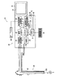
以下では、図面を参照して本発明の実施形態である電子内視鏡装置10について説明する。図1は、本実施形態における電子内視鏡装置10のブロック図である。
【0016】
電子内視鏡装置10には、CCD11を有するビデオスコープ20と、CCD11から読み出される信号を処理するプロセッサ30とが備えられている。ビデオスコープ20は、プロセッサ30と着脱自在に接続される。
【0017】
ビデオスコープ20内にはライトガイド12が挿通されている。ライトガイド12は、光源部22から放射される光を伝達する光ファイバ束であり、ライトガイド入射端12Aと光源部22との間には、光源部22内の光源から放射される光束の光量を調節するための絞り(図示せず)や、光をライトガイド入射端12Aに集光させるための集光レンズ(図示せず)が設けられている。ビデオスコープ20がプロセッサ30に接続され、光源部22内の光源から光が放射されると、光はライトガイド入射端12Aに入射し、ビデオスコープ20側にあるライトガイド12の出射端12Bから出射する。そして、ライトガイド12から出射した光により観察部位Sが照射される。
【0018】
光源部22においては、光源の光放射側に回転式RGBカラーフィルタ(図示せず)が設けられている。回転式RGBカラーフィルタは、所定の間隔を置いて設けられる赤色フィルタ、緑色フィルタおよび青色フィルタを備えている。このため、回転式RGBカラーフィルタがモータにより回転させられると、ライトガイド出射端12Bから赤色光、緑色光および青色光が順次放射され、観察部位Sにはこれらの光が順次照射されて、各色の光学的被写体像がCCD11の受光面に順次結像させられる。CCD11は、その光学的被写体像を1フレーム分のアナログ信号に光電変換し、生じた各色の1フレーム分のアナログ画素信号は、ビデオスコープ20内のCCDドライバ(図示せず)により順次読み出される。
【0019】
CCDドライバにより読み出された赤色(R)、緑色(G)および青色(B)の各色の1フレーム分のアナログ画素信号は、初段信号処理回路24に入力され、初段信号処理回路24においてデジタル画像信号に変換される。さらに、デジタル画像信号にはホワイトバランス調整、γ補正などの処理が施されて、各色毎に画像メモリ25に格納される。そして、デジタル画素信号に水平同期信号および垂直同期信号が付加されることにより、カラーデジタルビデオ信号(R、G、B)となる。さらに、カラーデジタルビデオ信号(R、G、B)には、拡大、縮小、ノイズリダクション等の処理が施されてカラーアナログビデオ信号に変換された後に、後段映像信号処理回路26へ送信される。カラーアナログビデオ信号は、後段映像信号処理回路26において出力レベルが調整されてからプリンタ36に送信され、この結果プリンタ36による被写体像の印刷が可能となる。なお、アナログ信号からデジタル信号への変換、デジタル信号からアナログ信号への変換、画像メモリ25への画素信号の取り込み、同期信号の作成などはタイミングコントローラ28によって制御される。
【0020】
一方、本実施形態においては、モニタ画面34を備えたモニタ32が、プロセッサ30と開閉自在に一体化されている。モニタ32が後述の閉じられた状態で、プロセッサ30の電源スイッチ(図示せず)がONの状態になると、マイクロスイッチ38が、モニタ32が閉じられていることを検出し、検出信号が、システムコントローラ21に送られる。
【0021】
システムコントローラ21は、受信した検出信号に基いた制御信号をCRTC(CRTコントローラ)29へ送り、さらにその制御信号に基づき、被写体像とは関わりのない輝度および色度調整用の所定の画面を表示させる表示指示信号が、CRTC29から画面表示用信号処理回路27へ送られる。画面表示用信号処理回路27は、表示指示信号に基いてモニタ32を制御し、これによりモニタ画面34では初期画面が表示される。
【0022】
プロセッサ30に設けられた輝度センサ40と色度センサ42は、モニタ画面上に表示される初期画面の対向する位置における輝度値および色度値を検出し、検出された輝度値および色度値のデータは、それぞれ輝度センサ40と色度センサ42とから、システムコントローラ21に送られる。
【0023】
システムコントローラ21によって受信された輝度値および色度値は、後述のように、既にシステムコントローラ21内のRAM(図示せず)に記録されている参照輝度値および参照色度値とそれぞれ比較される。参照輝度値および参照色度値の設定や変更は、プロセッサ30に接続されているキーボード44を用いて、数値を入力することにより行われる。
【0024】
先述の通り、本実施形態においては、使用開始時に初期画面を表示することが必要であるため、画面表示のために必要な信号をCRTC29から受信し、さらにモニタ32へ送信する画面表示用信号処理回路27が、後段映像信号処理回路26とは別に設けられている。そして、観察部位Sの映像の表示も、画面表示用信号処理回路27を介して行われるため、画像メモリ25において処理されたカラーアナログビデオ信号は、後段映像信号処理回路26と共に画面表示用信号処理回路27にも送信される。
【0025】
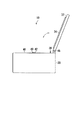
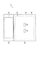
図2は、モニタ32が一体化されたプロセッサ30の側面図である。また、図3は、モニタ32が開いた状態のプロセッサ30の上面図である。
【0026】
モニタ画面34を備えたモニタ32は、ヒンジ48を介してプロセッサ30の天面に回転自在に取付けられており、矢印の方向に開閉可能である。プロセッサの上面であり、モニタ32が閉じられた状態においてモニタ32のモニタ画面34と近接して対向するモニタ対向面46上には、マイクロスイッチ38、輝度センサ40および色度センサ42が設けられている。マイクロスイッチ38のON/OFFにより、モニタ32が閉じられているか否かが判断可能であり、電子内視鏡装置10の電源がONである時に、マイクロスイッチ38によりモニタ32が閉じられていると判断されると、モニタ画面34上に所定の初期画面が映し出される。そして、輝度センサ40および色度センサ42により、輝度センサ40および色度センサ42と対向する初期画面の所定の位置における輝度および色度が検出される。
【0027】
モニタ対向面46上にあって、モニタ32が閉じた場合にモニタ画面34と対向する領域であるモニタ画面対向領域50の中心付近には、図3に示すように輝度センサ40および色度センサ42が設けられている。この時、外乱光を遮断するため、モニタ32は、閉じた場合にプロセッサ30側のモニタ対向面46に近接する、あるいは接するように設けられている。これにより、モニタ32が閉じられて初期画面がモニタ画面34上に表示され、初期画面上の輝度および色度が、外乱光の影響の少ない状態で検出される。
【0028】
輝度センサ40および色度センサ42は、それぞれ少なくとも赤(R)用の1画素、青(B)用の1画素、緑(G)用の2画素の4画素から構成されており、これらのフォトセルの配列は、モニタ32が閉じられた場合にモニタ画面34の対向する領域にあるフォトセルの配列と真向かいの位置にある。
【0029】
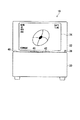
図4は、モニタ32が開いた状態のプロセッサ30の正面図である。
【0030】
本実施形態において、モニタ32が開かれ、映像がモニタ画面34上に表示されている場合、モニタ32、モニタ画面34、プロセッサ30、およびモニタ対向面46の位置関係は、図4のように示される。この時、マイクロスイッチ38は、モニタ32が開いていることを検出しており、初期画面の表示や、輝度センサ40および色度センサ42による輝度および色度の検出は、いずれも映像が表示される前のモニタ32が閉じている状態で行い、この状態では行われない。
【0031】
図5は、システムコントローラ21で行われる輝度・色度調整ルーチンを示すフローチャートである。電子内視鏡装置10のメインスイッチが操作され、ONの状態となるとルーチンが開始される。
【0032】
ステップS501では、マイクロスイッチ38がONの状態であるか否かが判断される。マイクロスイッチ38がONの状態である、すなわちモニタ32が閉じられていると判断されると、ステップS502に進む。マイクロスイッチ38がONの状態でないと判断されると、輝度・色度調整ルーチンは終了する。
【0033】
ステップS502では、閉じている状態でモニタ画面34上に輝度および色度調整用の所定の初期画面が表示される。ステップS503では、輝度センサ40および色度センサ42により、初期画面のそれぞれのセンサと対向する位置における輝度および色度が検出される。検出された輝度値および色度値のデータがシステムコントローラ21に送られると、ステップS504に進む。
【0034】
ステップS504においては、輝度センサにより検出され、システムコントローラ21に送信された輝度値(以下今回検出輝度値)BRが、基準輝度範囲Bに含まれる値であるか否かが判断される。この場合、今回検出輝度値BRと比較される基準輝度値Bは、予め設定されてシステムコントローラ21内のRAMに記録されている基準輝度範囲の上限値Bmaxおよび下限値Bminにより規定される範囲である。これらの比較結果により、(1)式に示されるように、今回検出輝度値BRが基準輝度範囲B内の値であると判断された場合にはステップS505に進み、(2)式あるいは(3)式に示されるように、今回輝度値BRが輝度基準範囲B外の値であると判断された場合にはステップS506に進む。
Bmin≦BR≦Bmax …(1)
BR<Bmin …(2)
Bmax<BR …(3)
【0035】
ステップS505では、前回の各センサ動作時に検出され、予めシステムコントローラ21内のRAMに記録されている前回検出輝度値Bpreおよび前回検出色度値Cpreが、今回輝度値BRおよび色度センサにより検出されてシステムコントローラ21に送信された色度値(以下今回検出色度値)CRと比較される。そして、前回検出輝度値Bpreおよび前回検出色度値Cpreが、それぞれ今回検出輝度値BRおよび今回検出色度値CRと実質上等しいか否かが判断される。なお、色度については、R、B、Gの各色要素ごとにそれぞれ比較が行われる。
【0036】
今回検出輝度値BRと前回検出輝度値Bpre、および今回検出色度値CRと前回検出色度値Cpreとが、それぞれ実質上等しいか否かは、今回検出輝度値BRと前回検出輝度値Bpreとの差、および今回検出色度値CRと前回検出色度値Cpreとの差が、予め設定されているそれぞれの許容範囲である輝度許容範囲Dbrおよび色度許容範囲Dcr内にあるか否かにより判断される。これらの差が、(4)式および(5)式に示されるようにいずれも輝度許容範囲Dbrおよび色度許容範囲Dcr内であって、今回検出輝度値BRおよび今回検出色度値CRのいずれもが、前回検出輝度値Bpreおよび前回検出色度値Cpreとそれぞれ実質上等しいと判断された場合、ステップS508に進む。一方、(6)式あるいは(7)式に示されるように、今回検出輝度値BRあるいは今回検出色度値CRのいずれかが、前回検出輝度値Bpreあるいは前回検出色度値Cpreと実質上異なると判断されると、ステップS507に進む。
|BR−Bpre|≦Dbr …(4)
|CR−Cpre|≦Dcr …(5)
|BR−Bpre|>Dbr …(6)
|CR−Cpre|>Dcr …(7)
【0037】
なお、前回の各センサ動作時に検出された輝度値および色度値に対して、後述のように補正が加えられていた場合においては、補正後の輝度値および色度値が、前回検出輝度値Bpreおよび前回検出色度値CpreとしてRAMに記録されている。従って、この場合においても、今回検出輝度値BRおよび今回検出色度値CRと比較されるのは、それぞれ補正後の前回検出輝度値Bpreおよび前回検出色度値Cpreとなる。
【0038】
ステップS504において、(2)式あるいは(3)式が示すように、今回検出輝度値BRが、予め設定されていた輝度基準範囲B外の値であった場合、モニタの異常や、モニタ画面用バックライトの寿命が尽きたことなどが予想される。このため、ステップS506においては、モニタ32の点検やモニタ画面34用バックライトの交換(モニタ32が液晶モニタの場合)等をオペレータに促すメッセージがモニタ画面34上に表示され、輝度・色度調整ルーチンは終了する。
【0039】
ステップS507においては、モニタ画面34上に映し出される輝度および色度調整用の初期画面の輝度、色度の表示について補正が行われる。すなわち、輝度センサ40および/または色度センサ42により検出される初期画面の所定の位置における輝度および/または色度が、前回検出輝度値Bpreおよび/または前回検出色度値Cpreとして検出されるように、モニタ画面に表示される初期画面の輝度/色度を補正させる信号が、システムコントローラ21からCRTC29を介して画面表示用信号処理回路27に送られる。そして、この信号に基いて、画面表示用信号処理回路27からモニタ32に対して、モニタ画面34による表示において輝度/色度を補正させる信号が送られ、これによりモニタ画面34上の初期画面表示の輝度/色度の補正が行われる。
【0040】
この補正が施されると、再びステップS503に進み、補正後の初期画面の所定の位置における輝度および色度が、再び輝度センサ40および色度センサ42により検出される。そして、補正後の初期画面における輝度値および色度値について、再びステップS504以降同様の判断、処理が行われ、補正後の輝度値および/または色度値が適正な値である前回検出輝度値Bpre/前回検出色度値Cpreと実質上等しくなるまで、ステップS503、ステップS504、ステップS505およびステップS507は繰り返し実行される。
【0041】
ステップS508においては、初期画面の所定の位置における輝度値および色度値として最終的に検出された値が、RAMに記録される。ここで、記録される輝度値および色度値は、先述のステップS507における初期画面の補正が行われなかった場合、輝度センサ40および色度センサ42により当初検出された今回検出輝度値BRおよび今回検出色度値CRである。一方、ステップS507で補正が行われた場合においては、補正後の最終的な輝度値である補正後輝度値Badjおよび補正後色度値Cadjが記録されることとなる。いずれにせよ、ステップS508においてRAMに記録された輝度値および色度値は、次回の輝度センサ40および色度センサ42の動作時に検出される輝度値および色度値と、比較される前回検出輝度値Bpreおよび前回検出色度値Cpreとなる。輝度値および色度値の記録が終了すると、輝度・色度調整ルーチンは終了する。
【0042】
本実施形態においては、ステップS504において今回検出輝度値BRが輝度基準範囲B内の値であるか否かが判断された後に、ステップS505において今回検出輝度値BRおよび今回検出色度値CRが、それぞれ前回検出輝度値Bpreおよび前回検出色度値Cpreに実質上等しいか否かが判断されているが、このステップS504とステップS505との実施順序は、逆であっても良い。
【0043】
輝度値が一般的にモニタ画面の使用と共に低下する傾向にあることから、ステップS504における基準輝度範囲Bとして、上限値Bmaxおよび下限値Bminを設定するのではなく、下限値Bminのみを設定しても良い。この場合、(8)式に示されるように、今回検出輝度値BRが、輝度基準範囲B内の値であると判断された場合にはステップS505に進み、(2)式に示されるように、今回輝度値BRが輝度基準範囲B外の値であると判断された場合にはステップS506に進む。
Bmin≦BR …(8)
【0044】
本実施形態におけるモニタ32は、共通の回転軸であるヒンジ48を介してプロセッサ30と開閉自在に一体化されているが、マイクロスイッチ38、輝度センサ40および色度センサ42が設けられているモニタ対向面46をプロセッサ30の側面とすると共に、モニタ32が、モニタ対向面46に対してスライドすることにより開閉自在にプロセッサ30と一体化される構造としても良い。また、モニタ32が、伸縮自在の部材によりプロセッサ30に取付けられることにより、開閉自在とされても良い。
【0045】
図5のステップS506において、オペレータにモニタ32の点検やモニタ画面34用バックライトの交換等を促す警告は、モニタ画面34上の表示の他に、音声によるものであっても良い。
【0046】
本発明の実施形態として電子内視鏡装置10について説明したが、デジタルカメラ、デジタルビデオカメラ、表示機能付き携帯電話などの表示機能付き撮像装置や、ノート型パーソナルコンピュータなどの一体型モニタを備えた電子機器に本発明を適用しても良い。
【0047】
本発明におけるモニタ画面34としては、液晶モニタやプラズマディスプレイパネル等が使用可能である。
【0048】
【発明の効果】
以上のように本発明によれば、モニタに起因する輝度や色度の変化に対しても、モニタ表示における輝度や色度を自動的に適切なものに調整することが可能な表示機能付き電子機器を提供できる。さらに、モニタ画面表示における異常などをオペレータに報知させることが可能となる。
【図面の簡単な説明】
【図1】本実施形態である電子内視鏡装置のブロック図である。
【図2】モニタが一体化されたプロセッサの側面図である。
【図3】モニタが開いた状態でのプロセッサの上面図である。
【図4】モニタが開いた状態でのプロセッサの正面図である。
【図5】輝度・色度調整ルーチンを示すフローチャートである。
【符号の説明】
10 電子内視鏡装置
11 CCD
20 ビデオスコープ
21 システムコントローラ(輝度比較手段・色度比較手段)
25 画像メモリ
26 後段映像信号処理回路
27 画面表示用信号処理回路
28 タイミングコントローラ
30 プロセッサ
32 モニタ
34 モニタ画面
38 マイクロスイッチ(モニタ画面開閉判断手段)
40 輝度センサ
42 色度センサ
46 モニタ対向面
48 ヒンジ(回転軸)
50 モニタ画面対向領域
BR 今回検出輝度値
CR 今回検出色度値
Bmax 基準輝度範囲の上限値
Bmin 基準輝度範囲の下限値
Bpre 前回検出輝度値
Cpre 前回検出色度値
Dbr 輝度許容範囲
Dcr 色度許容範囲[0001]
BACKGROUND OF THE INVENTION
The present invention relates to automatic adjustment of brightness and chromaticity in display on a monitor screen of an electronic apparatus equipped with an integrated monitor such as an electronic endoscope apparatus, a notebook personal computer, and a mobile phone with a camera.
[0002]
[Prior art]
Conventionally, in an electronic device such as an electronic endoscope apparatus in which a monitor is independent from a main body where signal processing is performed, an image is displayed on a monitor screen based on a signal transmitted from the main body via an external terminal. . In this case, the brightness and chromaticity of the monitor screen display are adjusted as necessary by operating buttons near the monitor screen. In addition, in an electronic device having an integrated monitor, brightness and color are adjusted by a button operation or the like in a personal computer or the like, but in a digital camera or the like, white balance adjustment or brightness adjustment is automatically performed on the imaging device side. Etc. are performed. (For example, refer to Patent Document 1).
[0003]
[Patent Document 1]
JP 2001-333432 A (paragraphs [0006] to [0013])
[0004]
[Problems to be solved by the invention]
2. Description of the Related Art Conventionally, in electronic devices such as an electronic endoscope apparatus with an independent monitor, and personal computers among monitor-integrated electronic devices, button operations and the like are necessary to adjust brightness and color in monitor screen display. On the other hand, in an electronic device having an integrated monitor, a digital camera or the like displays a subject image based on a transmitted image signal. However, luminance and chromaticity are already appropriate in an image processing circuit. Has been adjusted. However, once transmitted from the image processing circuit, the transmitted image signal is displayed as it is, and this is caused by the monitor, such as a decrease in the brightness of the emitted light due to the change over time of the backlight for illuminating the monitor screen on the liquid crystal monitor. Changes in brightness and chromaticity are not automatically adjusted.
[0005]
Therefore, in the present invention, it is possible to automatically adjust the luminance and chromaticity in the monitor display to appropriate ones even with respect to the change in luminance and chromaticity caused by the monitor, and further, abnormality in the monitor screen display, etc. It is an object of the present invention to provide a monitor-integrated electronic device capable of reporting the above.
[0006]
[Means for Solving the Problems]
In the first electronic endoscope apparatus of the present invention, a monitor having a monitor screen for displaying an image is integrated with a processor so as to be freely opened and closed. The processor is installed on the monitor facing surface that faces the monitor screen in proximity to or in contact with the monitor screen when the monitor is closed, and the brightness value of the initial screen for brightness and chromaticity adjustment that is displayed on the monitor screen. And a chromaticity sensor for detecting the chromaticity value of the initial screen. The processor further includes a monitor screen open / close determining means for determining whether the monitor is open / closed, an initial screen display means for displaying an initial screen on the monitor screen when it is determined that the monitor is closed, and a detected brightness value as a predetermined value. A luminance comparison means for comparing with the comparison luminance value; and a chromaticity comparison means for comparing the detected chromaticity value with a predetermined comparison chromaticity value, and further, the result of comparison with the comparison luminance value by the luminance comparison means A luminance correcting unit that corrects the luminance value based on the result, and a chromaticity correcting unit that corrects the chromaticity value based on the result of comparison with the comparative chromaticity value by the chromaticity comparing unit.
[0007]
The second electronic endoscope apparatus of the present invention requires reference luminance range setting means capable of setting a reference luminance range indicating a range to be satisfied by the luminance value detected by the luminance sensor, and the operator needs to check the monitor screen. It is preferable to further have an informing means for informing the sex. The upper limit value and / or lower limit value of the reference brightness range set by the reference brightness range setting means and the brightness value detected by the brightness sensor are compared by the brightness comparison means. As a result, when the detected luminance value is a value larger than the upper limit value of the reference luminance range or a value smaller than the lower limit value of the reference luminance range, it is desirable that the notification unit operates.
[0008]
The third electronic endoscope apparatus of the present invention is capable of recording the luminance value of the initial screen detected by the luminance sensor and the chromaticity value of the initial screen detected by the chromaticity sensor. It is preferable to further have chromaticity recording means. Then, the previously detected luminance value detected by the luminance recording means and recorded by the luminance recording means is compared with the luminance value detected by the luminance sensor by the luminance comparing means, and when the previous chromaticity sensor is operated. It is desirable that the previously detected chromaticity value detected and recorded by the chromaticity recording means is compared with the chromaticity value detected by the chromaticity sensor by the chromaticity comparison means.
[0009]
The monitor of the present invention opens and closes by rotating the shaft, for example.
[0010]
The brightness sensor and chromaticity sensor of the present invention are preferably installed in the vicinity of the center of the monitor facing surface in order to avoid the influence of ambient light when detecting the brightness and chromaticity. Further, when the monitor is closed, it is desirable that the monitor and the processor, or the monitor and the main body be close to or in contact with each other to block ambient light.
[0011]
When the monitor in the present invention is closed, the photocell arrangement of the luminance sensor matches the arrangement of the photocells in the area on the monitor screen facing the luminance sensor. Similarly, the photocell arrangement of the chromaticity sensor is It is desirable to match the arrangement of the photocells in the area on the monitor screen facing the chromaticity sensor.
[0012]
The chromaticity sensor according to the present invention is preferably composed of at least one pixel for red (R), one pixel for blue (B), and two pixels for green (G).
[0013]
In the electronic apparatus of the present invention, a monitor having a monitor screen is integrated with the main body so as to be freely opened and closed. When the monitor is closed, the monitor is placed on the monitor facing surface that is close to or in contact with the monitor screen, and the brightness value of the initial screen for brightness and chromaticity adjustment that is displayed on the monitor screen. And a chromaticity sensor for detecting the chromaticity value of the initial screen. The main body further includes a monitor screen open / close determining means for determining whether the monitor is open / closed, an initial screen display means for displaying an initial screen on the monitor screen when it is determined that the monitor is closed, and a detected brightness value as a predetermined value. Luminance comparison means for comparing with the comparison luminance value, and chromaticity comparison means for comparing the detected chromaticity value with a predetermined comparison chromaticity value, and further, the luminance value based on the result of comparison by the luminance comparison means And a chromaticity correction unit that corrects the chromaticity value based on the result of comparison by the chromaticity comparison unit.
[0014]
As the monitor screen in the present invention, for example, a liquid crystal monitor is used.
[0015]
DETAILED DESCRIPTION OF THE INVENTION
Hereinafter, an
[0016]
The
[0017]
A
[0018]
In the
[0019]
The analog pixel signals for one frame of each color of red (R), green (G), and blue (B) read by the CCD driver are input to the first-stage
[0020]
On the other hand, in the present embodiment, a
[0021]
The
[0022]
The
[0023]
The luminance value and chromaticity value received by the
[0024]
As described above, in this embodiment, since it is necessary to display an initial screen at the start of use, a signal necessary for screen display is received from the
[0025]
FIG. 2 is a side view of the
[0026]
A
[0027]
As shown in FIG. 3, a
[0028]
Each of the
[0029]
FIG. 4 is a front view of the
[0030]
In this embodiment, when the
[0031]
FIG. 5 is a flowchart showing a luminance / chromaticity adjustment routine performed by the
[0032]
In step S501, it is determined whether or not the
[0033]
In step S502, a predetermined initial screen for brightness and chromaticity adjustment is displayed on the
[0034]
In step S <b> 504, it is determined whether or not the luminance value (hereinafter referred to as the current detected luminance value) BR detected by the luminance sensor and transmitted to the
Bmin ≦ BR ≦ Bmax (1)
BR <Bmin (2)
Bmax <BR (3)
[0035]
In step S505, the previously detected brightness value Bpre and the previously detected chromaticity value Cpre, which are detected during the previous sensor operation and recorded in advance in the RAM in the
[0036]
Whether or not the current detection luminance value BR and the previous detection luminance value Bpre, and the current detection chromaticity value CR and the previous detection chromaticity value Cpre are substantially equal to each other is determined based on the current detection luminance value BR and the previous detection luminance value Bpre. , And whether or not the difference between the current detected chromaticity value CR and the previously detected chromaticity value Cpre is within the preset allowable luminance range Dbr and chromaticity allowable range Dcr. To be judged. These differences are within the allowable luminance range Dbr and the allowable chromaticity range Dcr as shown in the equations (4) and (5), and any of the current detected luminance value BR and the current detected chromaticity value CR. If it is determined that the previous detected luminance value Bpre and the previously detected chromaticity value Cpre are substantially equal to each other, the process proceeds to step S508. On the other hand, as shown in the equation (6) or (7), either the current detection luminance value BR or the current detection chromaticity value CR is substantially different from the previous detection luminance value Bpre or the previous detection chromaticity value Cpre. If it is determined, the process proceeds to step S507.
| BR-Bpre | ≦ Dbr (4)
| CR-Cpre | ≦ Dcr (5)
| BR-Bpre |> Dbr (6)
| CR-Cpre |> Dcr (7)
[0037]
If the brightness and chromaticity values detected during each previous sensor operation have been corrected as described later, the corrected brightness and chromaticity values are the previously detected brightness values. Bpre and the previously detected chromaticity value Cpre are recorded in the RAM. Accordingly, also in this case, the previously detected luminance value Bpre and the previously detected chromaticity value Cpre after correction are respectively compared with the current detected luminance value BR and the current detected chromaticity value CR.
[0038]
In step S504, if the currently detected luminance value BR is a value outside the preset luminance reference range B, as shown by the equation (2) or (3), the monitor abnormality or monitor screen The lifetime of the backlight is expected to be exhausted. For this reason, in step S506, a message prompting the operator to check the
[0039]
In step S507, the display of the luminance and chromaticity displayed on the
[0040]
When this correction is performed, the process proceeds again to step S503, and the
[0041]
In step S508, values finally detected as luminance values and chromaticity values at predetermined positions on the initial screen are recorded in the RAM. Here, the brightness value and chromaticity value to be recorded are the current detection brightness value BR and the current detection brightness value BR initially detected by the
[0042]
In this embodiment, after it is determined in step S504 whether or not the current detection luminance value BR is a value within the luminance reference range B, in step S505, the current detection luminance value BR and the current detection chromaticity value CR are Although it is determined whether or not the previous detected luminance value Bpre and the previous detected chromaticity value Cpre are substantially equal to each other, the execution order of step S504 and step S505 may be reversed.
[0043]
Since the luminance value generally tends to decrease with the use of the monitor screen, the upper limit value Bmax and the lower limit value Bmin are not set as the reference luminance range B in step S504, but only the lower limit value Bmin is set. Also good. In this case, as shown in the equation (8), when it is determined that the current detected luminance value BR is a value within the luminance reference range B, the process proceeds to step S505, and as shown in the equation (2). If it is determined that the current brightness value BR is outside the brightness reference range B, the process proceeds to step S506.
Bmin ≦ BR (8)
[0044]
The
[0045]
In step S506 in FIG. 5, the warning that prompts the operator to check the
[0046]
Although the
[0047]
As the
[0048]
【The invention's effect】
As described above, according to the present invention, an electronic device with a display function that can automatically adjust the luminance and chromaticity in the monitor display to appropriate ones even when the luminance and chromaticity are changed due to the monitor. Equipment can be provided. Furthermore, it is possible to notify the operator of an abnormality in the monitor screen display.
[Brief description of the drawings]
FIG. 1 is a block diagram of an electronic endoscope apparatus according to an embodiment.
FIG. 2 is a side view of a processor with an integrated monitor.
FIG. 3 is a top view of the processor with the monitor open.
FIG. 4 is a front view of the processor with the monitor opened.
FIG. 5 is a flowchart showing a luminance / chromaticity adjustment routine.
[Explanation of symbols]
10 Electronic Endoscope Device 11 CCD
20
25
40
50 Monitor screen facing area BR Current detection brightness value CR Current detection chromaticity value Bmax Upper limit value of reference brightness range Bmin Lower limit value of reference brightness range Bpre Previous detection brightness value Cpre Previous detection chromaticity value Dbr Brightness tolerance range Dcr Chromaticity tolerance range
Claims (14)
前記プロセッサが、
前記モニタが閉じた場合に前記モニタ画面と近接あるいは接触して対向するモニタ対向面と、
前記モニタ対向面上に設置され、モニタ画面に表示される輝度調整用の初期画面の輝度値を検出する輝度センサと、
前記モニタの開閉を判断するモニタ画面開閉判断手段と、
前記モニタが閉じていると判断された場合、前記モニタ画面に前記初期画面を表示させる初期画面表示手段と、
前記輝度値を所定の比較輝度値と比較する輝度比較手段と、
前記輝度比較手段により比較された結果に基いて輝度値を補正する輝度補正手段とを備えることを特徴とする電子内視鏡装置。A monitor having a monitor screen for displaying an image is an electronic endoscope device integrated with a processor so as to be freely opened and closed,
The processor is
A monitor-facing surface that faces the monitor screen in proximity or contact when the monitor is closed;
A luminance sensor that is installed on the monitor facing surface and detects a luminance value of an initial screen for luminance adjustment displayed on the monitor screen;
Monitor screen open / close determining means for determining opening / closing of the monitor;
When it is determined that the monitor is closed, initial screen display means for displaying the initial screen on the monitor screen;
Luminance comparison means for comparing the luminance value with a predetermined comparative luminance value;
An electronic endoscope apparatus comprising: a luminance correction unit that corrects a luminance value based on a result of comparison by the luminance comparison unit.
前記プロセッサが、
前記モニタが閉じた場合に前記モニタ画面と近接あるいは接触して対向するモニタ対向面と、
前記モニタ対向面上に設置され、モニタ画面に表示される色度調整用の初期画面の色度値を検出する色度センサと、
前記モニタの開閉を判断するモニタ画面開閉判断手段と、
前記モニタが閉じていると判断された場合、前記モニタ画面に前記初期画面を表示させる初期画面表示手段と、
前記色度値を所定の比較色度値と比較する色度比較手段と、
前記色度比較手段により比較された結果に基いて色度値を補正する色度補正手段とを備えることを特徴とする電子内視鏡装置。A monitor having a monitor screen for displaying an image is an electronic endoscope device integrated with a processor so as to be freely opened and closed,
The processor is
A monitor-facing surface that faces the monitor screen in proximity or contact when the monitor is closed;
A chromaticity sensor installed on the monitor facing surface and detecting a chromaticity value of an initial screen for chromaticity adjustment displayed on the monitor screen;
Monitor screen open / close determining means for determining opening / closing of the monitor;
When it is determined that the monitor is closed, initial screen display means for displaying the initial screen on the monitor screen;
Chromaticity comparison means for comparing the chromaticity value with a predetermined comparative chromaticity value;
An electronic endoscope apparatus comprising: chromaticity correction means for correcting a chromaticity value based on a result of comparison by the chromaticity comparison means.
オペレータに対して前記モニタ画面の点検の必要性を知らせる報知手段とをさらに有し、
前記基準輝度範囲設定手段により設定された前記基準輝度範囲が上限値および/または下限値で規定され、
前記基準輝度範囲の上限値および/または下限値と、前記輝度センサにより検出された前記輝度値とが前記輝度比較手段により比較され、
前記輝度値が前記基準輝度範囲の上限値よりも大きい値あるいは前記基準輝度範囲の下限値よりも小さい値であった場合に、前記報知手段が動作することを特徴とする請求項1に記載の電子内視鏡装置。A reference luminance range setting means capable of setting a reference luminance range indicating a range to be satisfied by the luminance value;
A notification means for notifying an operator of the necessity of inspection of the monitor screen;
The reference luminance range set by the reference luminance range setting means is defined by an upper limit value and / or a lower limit value;
The upper limit value and / or lower limit value of the reference luminance range and the luminance value detected by the luminance sensor are compared by the luminance comparison means,
2. The notification means operates when the luminance value is larger than an upper limit value of the reference luminance range or smaller than a lower limit value of the reference luminance range. Electronic endoscope device.
前記所定の比較輝度値が、前回の前記輝度センサ動作時に検出されて前記輝度記録手段により記録されている前回検出輝度値であって、
前記前回検出輝度値と前記輝度値とを、前記輝度比較手段により比較することを特徴とする請求項1に記載の電子内視鏡装置。A luminance recording means capable of recording the luminance value of the initial screen detected by the luminance sensor;
The predetermined comparison brightness value is a previously detected brightness value detected by the brightness recording means and detected during the previous brightness sensor operation;
The electronic endoscope apparatus according to claim 1, wherein the previously detected luminance value and the luminance value are compared by the luminance comparing unit.
前記所定の比較色度値が、前回の前記色度センサ動作時に検出されて前記色度記録手段により記録されている前回検出色度値であって、
前記前回検出色度値と前記色度値とを、前記色度比較手段により比較することを特徴とする請求項2に記載の電子内視鏡装置。Chromaticity recording means capable of recording the chromaticity value of the initial screen detected by the chromaticity sensor,
The predetermined comparison chromaticity value is a previously detected chromaticity value that is detected by the chromaticity recording unit and is detected during the previous chromaticity sensor operation,
3. The electronic endoscope apparatus according to claim 2, wherein the previously detected chromaticity value and the chromaticity value are compared by the chromaticity comparison unit.
前記本体が、
前記モニタが閉じた場合に前記モニタ画面と近接あるいは接触して対向するモニタ対向面と、
前記モニタ対向面上に設置され、モニタ画面に表示される輝度調整用の初期画面の輝度値を検出する輝度センサと、
前記モニタの開閉を判断するモニタ画面開閉判断手段と、
前記モニタが閉じていると判断された場合、前記モニタ画面に前記初期画面を表示させる初期画面表示手段と、
前記輝度値を所定の比較輝度値と比較する輝度比較手段と、
前記輝度比較手段により比較された結果に基いて輝度値を補正する輝度補正手段とを備えることを特徴とする電子機器。A monitor having a monitor screen is an electronic device integrated with the main body so as to be freely opened and closed,
The body is
A monitor-facing surface that faces the monitor screen in proximity or contact when the monitor is closed;
A luminance sensor that is installed on the monitor facing surface and detects a luminance value of an initial screen for luminance adjustment displayed on the monitor screen;
Monitor screen open / close determining means for determining opening / closing of the monitor;
When it is determined that the monitor is closed, initial screen display means for displaying the initial screen on the monitor screen;
Luminance comparison means for comparing the luminance value with a predetermined comparative luminance value;
An electronic apparatus comprising: a luminance correction unit that corrects a luminance value based on a result of comparison by the luminance comparison unit.
前記本体が、
前記モニタが閉じた場合に前記モニタ画面と近接あるいは接触して対向するモニタ対向面と、
前記モニタ対向面上に設置され、モニタ画面に表示される色度調整用の初期画面の色度値を検出する色度センサと、
前記モニタの開閉を判断するモニタ画面開閉判断手段と、
前記モニタが閉じていると判断された場合、前記モニタ画面に前記初期画面を表示させる初期画面表示手段と、
前記色度値を所定の比較色度値と比較する色度比較手段と、
前記色度比較手段により比較された結果に基いて色度値を補正する色度補正手段とを備えることを特徴とする電子機器。A monitor having a monitor screen is an electronic device integrated with the main body so as to be freely opened and closed,
The body is
A monitor-facing surface that faces the monitor screen in proximity or contact when the monitor is closed;
A chromaticity sensor installed on the monitor facing surface and detecting a chromaticity value of an initial screen for chromaticity adjustment displayed on the monitor screen;
Monitor screen open / close determining means for determining opening / closing of the monitor;
When it is determined that the monitor is closed, initial screen display means for displaying the initial screen on the monitor screen;
Chromaticity comparison means for comparing the chromaticity value with a predetermined comparative chromaticity value;
An electronic apparatus comprising: chromaticity correction means for correcting chromaticity values based on a result of comparison by the chromaticity comparison means.
Priority Applications (1)
| Application Number | Priority Date | Filing Date | Title |
|---|---|---|---|
| JP2003209683A JP2005073718A (en) | 2003-08-29 | 2003-08-29 | Electronic endoscope apparatus with integrated monitor and electronic apparatus |
Applications Claiming Priority (1)
| Application Number | Priority Date | Filing Date | Title |
|---|---|---|---|
| JP2003209683A JP2005073718A (en) | 2003-08-29 | 2003-08-29 | Electronic endoscope apparatus with integrated monitor and electronic apparatus |
Publications (1)
| Publication Number | Publication Date |
|---|---|
| JP2005073718A true JP2005073718A (en) | 2005-03-24 |
Family
ID=34402528
Family Applications (1)
| Application Number | Title | Priority Date | Filing Date |
|---|---|---|---|
| JP2003209683A Withdrawn JP2005073718A (en) | 2003-08-29 | 2003-08-29 | Electronic endoscope apparatus with integrated monitor and electronic apparatus |
Country Status (1)
| Country | Link |
|---|---|
| JP (1) | JP2005073718A (en) |
Cited By (3)
| Publication number | Priority date | Publication date | Assignee | Title |
|---|---|---|---|---|
| JP2009288445A (en) * | 2008-05-28 | 2009-12-10 | Olympus Corp | Electronic endoscope system |
| JP2010051633A (en) * | 2008-08-29 | 2010-03-11 | Fujifilm Corp | Processor for electronic endoscope |
| WO2022059293A1 (en) * | 2020-09-15 | 2022-03-24 | Hoya株式会社 | Processor for endoscope and endoscopic system |
Citations (9)
| Publication number | Priority date | Publication date | Assignee | Title |
|---|---|---|---|---|
| JPS63157595A (en) * | 1986-12-22 | 1988-06-30 | Olympus Optical Co Ltd | Color tone adjusting device in video signal processing unit for endoscope |
| JPH03159391A (en) * | 1989-11-16 | 1991-07-09 | Olympus Optical Co Ltd | Monitor picture photographing device |
| JPH04115687A (en) * | 1990-08-31 | 1992-04-16 | Sony Corp | Projection device |
| JPH07333581A (en) * | 1994-06-02 | 1995-12-22 | Mitsubishi Electric Corp | Liquid crystal display |
| JPH08152566A (en) * | 1994-11-29 | 1996-06-11 | Toshiba Corp | Endoscope device and color adjustment method for endoscope device |
| JPH10105106A (en) * | 1996-09-30 | 1998-04-24 | Nec Eng Ltd | Operation device with liquid crystal for machine guarding terminal equipment and contrast adjusting method |
| JPH11123292A (en) * | 1991-08-24 | 1999-05-11 | Brother Ind Ltd | Sewing machine display |
| JP2001041852A (en) * | 1999-07-30 | 2001-02-16 | Fujitsu Kiden Ltd | Display abnormality-detecting apparatus, and photosensor unit |
| JP2002017666A (en) * | 2000-06-30 | 2002-01-22 | Olympus Optical Co Ltd | Simple endoscope image and voice transmitter-receiver |
-
2003
- 2003-08-29 JP JP2003209683A patent/JP2005073718A/en not_active Withdrawn
Patent Citations (9)
| Publication number | Priority date | Publication date | Assignee | Title |
|---|---|---|---|---|
| JPS63157595A (en) * | 1986-12-22 | 1988-06-30 | Olympus Optical Co Ltd | Color tone adjusting device in video signal processing unit for endoscope |
| JPH03159391A (en) * | 1989-11-16 | 1991-07-09 | Olympus Optical Co Ltd | Monitor picture photographing device |
| JPH04115687A (en) * | 1990-08-31 | 1992-04-16 | Sony Corp | Projection device |
| JPH11123292A (en) * | 1991-08-24 | 1999-05-11 | Brother Ind Ltd | Sewing machine display |
| JPH07333581A (en) * | 1994-06-02 | 1995-12-22 | Mitsubishi Electric Corp | Liquid crystal display |
| JPH08152566A (en) * | 1994-11-29 | 1996-06-11 | Toshiba Corp | Endoscope device and color adjustment method for endoscope device |
| JPH10105106A (en) * | 1996-09-30 | 1998-04-24 | Nec Eng Ltd | Operation device with liquid crystal for machine guarding terminal equipment and contrast adjusting method |
| JP2001041852A (en) * | 1999-07-30 | 2001-02-16 | Fujitsu Kiden Ltd | Display abnormality-detecting apparatus, and photosensor unit |
| JP2002017666A (en) * | 2000-06-30 | 2002-01-22 | Olympus Optical Co Ltd | Simple endoscope image and voice transmitter-receiver |
Cited By (6)
| Publication number | Priority date | Publication date | Assignee | Title |
|---|---|---|---|---|
| JP2009288445A (en) * | 2008-05-28 | 2009-12-10 | Olympus Corp | Electronic endoscope system |
| JP2010051633A (en) * | 2008-08-29 | 2010-03-11 | Fujifilm Corp | Processor for electronic endoscope |
| WO2022059293A1 (en) * | 2020-09-15 | 2022-03-24 | Hoya株式会社 | Processor for endoscope and endoscopic system |
| JP2022048866A (en) * | 2020-09-15 | 2022-03-28 | Hoya株式会社 | Processor for endoscope and endoscope system |
| JP7229210B2 (en) | 2020-09-15 | 2023-02-27 | Hoya株式会社 | Endoscope processor and endoscope system |
| US12150622B2 (en) | 2020-09-15 | 2024-11-26 | Hoya Corporation | Processor for endoscope and endoscopic system |
Similar Documents
| Publication | Publication Date | Title |
|---|---|---|
| EP1804518B1 (en) | Method and device for adjusting image color in image projector | |
| US7286177B2 (en) | Digital camera | |
| JP5877277B2 (en) | Imaging apparatus and image display method | |
| JP4282610B2 (en) | CAMERA, PORTABLE COMMUNICATION DEVICE EQUIPPED WITH THE CAMERA, SHOOTING METHOD AND PROGRAM | |
| JP2005073718A (en) | Electronic endoscope apparatus with integrated monitor and electronic apparatus | |
| US8532378B2 (en) | Imaging device, method of adjusting color shift of display monitor and color shift adjuster of display monitor | |
| US20050128313A1 (en) | Photographing apparatus having a liquid-crystal display | |
| JP2009282436A (en) | Liquid crystal display device and liquid crystal display method | |
| JP2010177821A (en) | Imaging apparatus and imaging method | |
| JP4222130B2 (en) | White balance control device and electronic device | |
| JP2014023828A (en) | Endoscope apparatus | |
| JP2011015738A (en) | Printing system | |
| JP2005130325A (en) | Imaging device | |
| WO2014132423A1 (en) | Video analysis device, display device, measurement method for display device, video correction method for display device | |
| JP5044327B2 (en) | Imaging device | |
| JP2009157289A (en) | Information processing apparatus having chromaticity adjustment function and display control method of the information processing apparatus | |
| JP2010004462A (en) | Mobile terminal equipment | |
| JP2004363898A (en) | Imaging display device | |
| JP2008061170A (en) | Image scanner system and image scanner apparatus | |
| JP2006324926A (en) | Portable terminal device and control method thereof | |
| JP2004194308A (en) | White balance adjustment device for endoscope and electronic endoscope device | |
| JP2007111326A (en) | Endoscope system | |
| JP2003339635A (en) | Electronic endoscope | |
| KR100771638B1 (en) | Image quality control system and control method | |
| JP4279488B2 (en) | Imaging device |
Legal Events
| Date | Code | Title | Description |
|---|---|---|---|
| A621 | Written request for application examination |
Free format text: JAPANESE INTERMEDIATE CODE: A621 Effective date: 20060706 |
|
| A711 | Notification of change in applicant |
Free format text: JAPANESE INTERMEDIATE CODE: A712 Effective date: 20080501 |
|
| A977 | Report on retrieval |
Free format text: JAPANESE INTERMEDIATE CODE: A971007 Effective date: 20090911 |
|
| A131 | Notification of reasons for refusal |
Free format text: JAPANESE INTERMEDIATE CODE: A131 Effective date: 20091006 |
|
| A521 | Request for written amendment filed |
Free format text: JAPANESE INTERMEDIATE CODE: A523 Effective date: 20091207 |
|
| A131 | Notification of reasons for refusal |
Free format text: JAPANESE INTERMEDIATE CODE: A131 Effective date: 20100106 |
|
| A02 | Decision of refusal |
Free format text: JAPANESE INTERMEDIATE CODE: A02 Effective date: 20100428 |
|
| A761 | Written withdrawal of application |
Free format text: JAPANESE INTERMEDIATE CODE: A761 Effective date: 20100614 |