JP2005055352A - Diagnostic device and diagnostic system loaded with diagnostic device - Google Patents
Diagnostic device and diagnostic system loaded with diagnostic device Download PDFInfo
- Publication number
- JP2005055352A JP2005055352A JP2003287793A JP2003287793A JP2005055352A JP 2005055352 A JP2005055352 A JP 2005055352A JP 2003287793 A JP2003287793 A JP 2003287793A JP 2003287793 A JP2003287793 A JP 2003287793A JP 2005055352 A JP2005055352 A JP 2005055352A
- Authority
- JP
- Japan
- Prior art keywords
- information
- diagnostic
- unit
- spot
- hybridization
- Prior art date
- Legal status (The legal status is an assumption and is not a legal conclusion. Google has not performed a legal analysis and makes no representation as to the accuracy of the status listed.)
- Withdrawn
Links
Images


Abstract
Description
本発明は、手術機器に組織・病変部の診断を行えるセンサを搭載して、手術中に短時間で正確に診断を行う診断装置及びこの診断装置を搭載する診断システムに関する。 The present invention relates to a diagnostic apparatus that mounts a sensor capable of diagnosing a tissue / lesioned part on a surgical instrument and accurately performs diagnosis in a short time during surgery, and a diagnostic system that includes the diagnostic apparatus.
一般に、手術中に執刀医の当初の所見に対して、予想外の所見があったり、切除範囲をその場で決定しなければ行けないときには、すぐに病理組織学的な情報を得たい場合がある。 In general, if there are unexpected findings on the surgeon's initial findings during surgery, or if the extent of resection must be determined on the spot, it may be desirable to obtain histopathological information immediately. is there.
この時行われる診断は、一般的に「術中迅速病理診断」(以下、術中迅速診断と称する)といわれている。この術中迅速診断は、手術中に組織の標本を作り、診断を行う検査であって、手術中に切り除いた効果や追加で切り除かなければならないかの必要性を判定し、治療効果向上が期待される重要な検査である。 The diagnosis performed at this time is generally referred to as “intraoperative rapid pathological diagnosis” (hereinafter referred to as intraoperative rapid diagnosis). This intraoperative rapid diagnosis is an examination that makes a tissue sample during the operation and makes a diagnosis, and determines the effect that was removed during the operation or whether it should be removed further, and the therapeutic effect is improved. Is an important test that is expected.
この術中迅速診断で顕微鏡遠隔観察システムを利用したものとしては、例えば、特許文献1に顕微鏡遠隔観察システムが開示されている。この顕微鏡遠隔観察システムは、遠隔操作者の病理医が観察側端末の操作して、伝送路で接続されて離れた病理室に設置される顕微鏡端末部を介して顕微鏡を遠隔的に観察して、病理医から病理室に在室する担当医へアドバイスを行うシステムである。
For example,
また、診断技術としては、特許文献2には、患者の遺伝子情報を用いて診断するという、医療システムが開示されている。
現在、実際に行われている術中迅速診断は、手術室で執刀医が一部切り取った病変部を病理検査室に運び、検査技師により組織が処理される。処理された病変部や生体組織は病理医の手に渡り顕微鏡等を用いて診断が行われる。 Currently, an intraoperative rapid diagnosis is carried out by carrying a lesion part partially cut by a surgeon in an operating room to a pathology laboratory and processing the tissue by an examination engineer. The processed lesion or living tissue is passed to the pathologist and diagnosed using a microscope or the like.
この診断結果が執刀医に戻るまでには、少なくとも十数分かかり、その間、手術は中断され、患者は術部を開いたまま待機している状態となってしまう。また、病理医の経験により限られた時間内で診断する必要があるため、通常の病理検査に比べて診断精度が落ちる虞がある。このような事態は、手術中における執刀医や患者に対して大きな負担を与えている。また、病理医にとっても短時間内に正確な診断を行わなければならないため、豊かな経験や多くの知識が要求されている。 It takes at least a dozen minutes for the diagnosis result to return to the surgeon, during which time the operation is interrupted and the patient is in a waiting state with the surgical site open. Moreover, since it is necessary to make a diagnosis within a limited time based on the experience of a pathologist, there is a risk that the diagnostic accuracy may be lower than that of a normal pathological examination. Such a situation places a heavy burden on the surgeon and patient during the operation. Moreover, since a pathologist must make an accurate diagnosis within a short time, rich experience and a lot of knowledge are required.
そこで本発明は、手術機器の一部に病理組織学的な情報を検出するセンサを搭載し、術中に執刀医が情報を知りたい組織部位にセンサを接触させることにより、その場で診断結果(遺伝子診断結果)を得ることができ、手術中における診断の時間短縮と精度向上を実現する診断装置を提供することを目的とする。 Therefore, the present invention is equipped with a sensor for detecting histopathological information in a part of the surgical instrument, and the surgeon contacts the tissue site where the surgeon wants to know the information during the operation, so that the diagnosis result ( It is an object of the present invention to provide a diagnostic apparatus that can obtain a genetic diagnosis result) and can realize a reduction in diagnosis time during surgery and an improvement in accuracy.
本発明は上記目的を達成するために、生体組織の一部を取得するとともにハイブリダイゼーションを行い、該生体組織の遺伝子情報を検出する遺伝子情報検出手段と、前記遺伝子情報検出手段による前記遺伝子情報を電気信号に変換して通信を行う送受信手段と、複数種の遺伝子情報に関連づけられた複数の診断情報が予め蓄積された病理データベースと、前記送受信手段から受信した前記遺伝子情報を前記病理データベースに照会して、該当する前記診断情報を検索する診断情報検索手段と、前記診断情報検索手段により検索された前記診断情報を表示する表示手段とを具備する診断装置を提供する。 In order to achieve the above object, the present invention obtains a part of a living tissue and performs hybridization to detect gene information of the living tissue, and the gene information detected by the gene information detecting means. Transmission / reception means for converting to electrical signals for communication, pathology database in which a plurality of diagnostic information associated with a plurality of types of gene information is stored in advance, and reference to the pathology database for the gene information received from the transmission / reception means Then, there is provided a diagnostic apparatus comprising diagnostic information search means for searching for relevant diagnostic information and display means for displaying the diagnostic information searched by the diagnostic information search means.
さらに、ジョーの先端部にDNAチップを備え、該DNAチップに付着した生体組織にハイブリダイゼーションを行い、光学的に検出した遺伝子情報を電気信号に変換して出力する遺伝子情報検出機構を有する鉗子と、前記鉗子のハンドル側に接続され、前記ハイブリダイゼーションを行うための薬液の供給及び回収と、前記DNAチップに対して照射光を伝搬し、電気信号化された遺伝子情報を無線信号に変換し送信する検出処理・情報送信部と、前記検出処理・情報送信部から離れて所在し、該検出処理・情報送信部からの無線信号を受信して、前記遺伝子情報を復号する情報受信部と、複数種の遺伝子情報に関連づけられた診断情報が予め蓄積された病理データベースと、前記受信した遺伝子情報を前記病理データベースに照会して、該当する前記診断情報を検索する診断情報検索部と、前記診断情報検索部により検索された前記診断情報の正誤の確認を行うために表示する確認表示手段と、前記確認表示手段により正しいと確認された前記診断情報を前記鉗子が所在する箇所の近傍に表示する表示部と、を具備する診断システムを提供する。 And a forceps having a gene information detection mechanism that includes a DNA chip at the tip of the jaw, performs hybridization on a biological tissue attached to the DNA chip, converts optically detected gene information into an electrical signal, and outputs the electrical signal. , Connected to the handle side of the forceps, supplying and collecting the chemical solution for performing the hybridization, propagating the irradiation light to the DNA chip, converting the converted genetic information into a radio signal and transmitting it A detection processing / information transmitting unit, an information receiving unit located apart from the detection processing / information transmitting unit, receiving a radio signal from the detection processing / information transmitting unit, and decoding the genetic information, and a plurality of A pathological database in which diagnostic information associated with the genetic information of the species is pre-stored, and the received genetic information is referred to the pathological database, A diagnostic information retrieval unit that retrieves the diagnostic information, a confirmation display unit that is displayed to confirm whether the diagnostic information retrieved by the diagnostic information retrieval unit is correct, and a confirmation display unit that confirms that the diagnostic information is correct. And a display unit for displaying the diagnostic information in the vicinity of the location where the forceps are located.
以上のような構成の診断装置は、手術室等で手術中に病理組織学的な情報を検出して、通信により別の場所に設けられているデータベースとの照会を行い、診断情報を迅速に求めることができる。 The diagnostic device configured as described above detects histopathological information during an operation in an operating room or the like, makes a reference to a database provided at another location by communication, and quickly obtains diagnostic information. Can be sought.
また、診断システムは、手術室等で手術中に病理組織学的な情報を検出して、通信により別の場所に設けられているデータベースとの照会を行い、得られた診断情報に対して、病理医の確認や診断が行われ、その診断情報が迅速に執刀医に知らせることができる。従って、診断に要する時間が短縮され即ち、手術に要する時間を短縮でき、且つ診断の精度が向上されることから、手術中における執刀医や患者に対する負担が軽減される。 In addition, the diagnostic system detects histopathological information during an operation in an operating room or the like, makes an inquiry with a database provided at another place by communication, and for the obtained diagnostic information, The pathologist is confirmed and diagnosed, and the diagnostic information can be quickly notified to the surgeon. Accordingly, the time required for diagnosis is shortened, that is, the time required for surgery can be shortened and the accuracy of diagnosis is improved, so that the burden on the surgeon and patient during the surgery is reduced.
本発明によれば、手術機器の一部に病理組織学的な情報を検出する遺伝子情報検出部を設け、術中に執刀医が情報を知りたい組織部位に遺伝子情報検出部を接触させて、その生体組織の一部を採取し、その場で病理医が確認した診断情報を得ることができ、手術中における診断の時間短縮と精度向上を実現する診断装置を提供することができる。本発明の診断システムは、精度の高い遺伝子情報を診察に用いて、且つ従来のように情報や診断情報のやり取りが通信にて行われるため、診断情報が執刀医に戻るのが僅かな時間で済み、手術の中断時間が短縮される。 According to the present invention, a genetic information detection unit for detecting histopathological information is provided in a part of the surgical instrument, and the surgeon is brought into contact with the tissue site where the surgeon wants to know information during the operation. It is possible to provide a diagnostic apparatus that collects a part of a living tissue and obtains diagnostic information confirmed by a pathologist on the spot, thereby realizing a reduction in diagnosis time and an improvement in accuracy during surgery. The diagnosis system of the present invention uses highly accurate genetic information for diagnosis, and exchange of information and diagnosis information is performed by communication as in the past, so that the diagnosis information is returned to the surgeon in a short time. The operation interruption time is shortened.
以下、図面を参照して本発明による最良の形態について詳細に説明する。
図1(a)は、本発明の診断装置の全体的な構成例を示すブロック構成図、図1(b)は、図1(a)に示す遺伝子情報検出部の構成例を示すブロック構成図である。
Hereinafter, the best mode of the present invention will be described in detail with reference to the drawings.
FIG. 1A is a block configuration diagram showing an overall configuration example of the diagnostic apparatus of the present invention, and FIG. 1B is a block configuration diagram showing a configuration example of the gene information detection unit shown in FIG. It is.
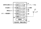
図1(a)に示すように、この診断装置1は、検査を所望する生体組織(又は、病変部)100を把持するための把持部2に設けられた遺伝子情報検出部3と、遺伝子情報検出部3にケーブル(チューブ)により接続される検出処理・情報送信部4と、この検出処理・情報送信部4から送信されたスポット情報信号(生体組織100の遺伝子情報等)を受信する情報受信部5と、受信された情報を処理するためのパソコンからなる情報処理部6と、処理された情報や操作指示等を表示する表示部7と、操作パネルやキーボード等からなり、設定や処理のための指示を入力する入力部8と、多種の生体組織のデータベースやDNAのデータベース等により構築される病理データベース9と、情報処理部6からの指示により、病理データベース9に記録されている情報に対して検出された遺伝子情報を検索して該当する診断情報を得る診断情報検索部10と、診断情報検索部10から得られた診断情報に基づく診断結果を内蔵する表示部に表示して病理医に確認(例えば、悪性又は良性等)させるパソコン等からなる病理医確認部11とで構成される。
As shown in FIG. 1 (a), the
この診断装置は、把持部2、遺伝子情報検出部3、検出処理・情報送信部4、情報受信部5、情報処理部6及び表示部7は、例えば、執刀医が在室する手術室内に配置される。また病理データベース8、診断情報検索部9及び病理医確認部10は、手術室内に配置する必要はなく、回線ケーブル例えばLAN等の通信回線38で接続して別室例えば、中央管理室に配置してもよい。この通信回線38に変わって、インターネット等のネットワークを用いて、遠隔地にある病院の手術室と通信を行えるようにしてもよい。さらに、通信回線38は、回線ケーブルによる有線通信だけではなく、無線通信又は光通信を用いてもよい。特に、画像のように情報量が多いものには、光通信が好適する。
In this diagnostic apparatus, for example, the grasping unit 2, the gene
図1(b)に示すように、この遺伝子情報検出部3は、把持部2の下側把持部2aに設けられる作用部12aと、上側把持部2bに設けられる作用部12bとで構成され、把持された際に、作用部12aと作用部12bは密閉状態となって対峙する。これらのうち、作用部12bは、後述する照射光を伝搬する光ケーブル39a、反射光の光電変換による電気信号(遺伝子情報)用のケーブル39b及びハイブリダイゼーションや洗浄を行うための洗浄液やターゲット溶液(蛍光物質を含み特定のDNAと反応する試料:以下、試料と称する)の薬液を送水するためのチューブ39c等で検出処理・情報送信部4に接続される。さらに、作用部12aは、上記薬液を排出するための排出用チューブ40で検出処理・情報送信部4と接続される。これらのケーブルやチューブは一体的にまとめられている。
As shown in FIG. 1 (b), the gene
図2(a)は、作用部12aを上から見た構成を示し、図2(b)は同図(a)の作用部12aの断面構成(A−A)を示す図である。図3(a)は、作用部12bの前処理・観察部21を上から見た構成を示し、図3(b)は、基準セル22の構成例を示し、図3(c)は、基準セル22の断面構成を示す図である。図4は、遺伝子情報検出部3と検出処理・情報送信部4との具体的な構成を示し説明する。図1(b)に示す把持部2(2a,2b)は、作用部12aと作用部12bとで生体組織100を挟んだ把持状態を示している。
2A shows a configuration of the
作用部12aは、図2(a)に示すように、DNAチップ14及び排出路16の排出口16aで構成される。この排出口16aは、図示された形状や配置に限定されるものではない。
As shown in FIG. 2A, the
DNAチップ14は、スライドガラス等からなるプレート基板上に複数種類のDNAが固相された多数のスポット(又は、プローブ)15がマトリックス状や互い違いに配列するように、スポッティングされてアレイ、所謂マイクロアレイとなっている。ここでは、スポット15はマトリックス状に配置されている。
The
また排出路16は、DNAチップ14に対してハイブリダイゼーションや洗浄を行う際に、DNAチップ14に掛けられた薬液、例えば試料や洗浄液を排出する。
The
一方、作用部12bには、把持された状態の時に、スポット15のそれぞれと対峙するように配置される多数の基準セル22からなる前処理・観察部21が設けられている。基準セル22の前面には、薬液の進入を防止するための透明部材、例えばガラス板22aが設けられている。この例では、基準セル22内には、光ケーブル39aに伝搬される照明光を照射する照射口24を中央に配置し、前記薬液の液体吐出部25と、受光部26とが斜め方向に配置されている。勿論、このような配置に限定されるものではない。前記受光部26は、フォトダイオード23からなり、スポット15からの蛍光色を含む反射光を受光し、光電変換により生成された蛍光強度を含む信号やスポットの識別情報及び位置情報を有するスポット情報信号を生成する。尚、フォトダイオード23は、CCD等の半導体撮像素子であってもよい。
On the other hand, the
また、図4に示すように、前記検出処理・情報送信部4は、送水ユニット31、吸引ユニット32、光源ユニット33と、検出ユニット34及び通信ユニット35で構成され、これらのユニットはパソコン等からなる制御部36により制御されている。これらのうち、送水ユニット31は、DNAチップ14にハイブリダイゼーションや洗浄を行うための試料や洗浄液の液体を送水路(チューブ39c)を経て液体吐出部25へ供給する。吸引ユニット32は、DNAチップ14へ供給された薬液を排出路16を経て回収する。
As shown in FIG. 4, the detection processing /
光源ユニット33は、光ファイバ27を経て基準セル22のそれぞれの照射口24へ光学的に接続して光源ユニット33からの光を伝搬して各スポットへ光を照射する。検出ユニット34は、基準セル22内の受光部26を含み、反応したスポット15からのスポット情報信号を生成する。通信ユニット35は、スポット情報信号を通信するのに適した無線信号又は光信号に変換して、アンテナ37により情報受信部5へ送信する。
The
尚、前記液体吐出部25においては、前記試料を50℃〜95℃程度に加熱するためのヒータを作用部12b内に内蔵してもよい。この加熱は、PCR反応を利用する場合に用いればよい。
In the
このような構成により、基準セル22は、全スポット15に光ファイバ24を透過した光を照射し、ハイブリダイゼーションにより反応したスポット15から蛍光色(蛍光強度)を含む反射光をフォトダイオード23で受光して、光電変換された電気信号として、ケーブルを通じて検出処理・情報送信部4へ送信する。
With such a configuration, the
次に、このように構成された診断装置における作用について説明する。
患者等の生体組織100の遺伝子情報を得るために、把持部2で、生体組織100を把持する。この把持した際に、生体組織100表面の一部をDNAチップ14に付着させる。その後、生体組織100から外して、把持部2を閉じた状態、つまり作用部12a、12bを合わせた密閉状態で、基準セル22の液体吐出部25から試料を流してハイブリダイゼーションを行い、反応後に洗浄する。そして、DNAチップ14の全スポット15へ照射口24から光を照射する。反応した各スポット15からの蛍光色を含む反射光をフォトダイオード23で受光して、光電変換により蛍光強度を含むスポット情報信号(遺伝子情報)を生成する。このスポット情報信号は、検出ユニット34により増幅やノイズ除去等の所定の処理が施された後、検出処理・情報送信部4により無線信号に変換されて、情報受信部5へ無線により送信される。情報受信部5は、受信したスポット情報信号を復号して、遺伝子情報として情報処理部6へ出力する。
Next, the operation of the thus configured diagnostic apparatus will be described.
In order to obtain genetic information of the
この情報処理部6は、予め定められたシーケンス(プログラム)により、この遺伝子情報による診断を行う。まず、この遺伝子情報は、診断情報検索10へ送出され、ここで病理データベース9に記録されているデータ(予め記録されたデータ又は過去の蓄積データ)と照らし合わせられて、該当するデータ(診断情報)が読み出される。診断情報検索部10は、読み出された診断情報を病理医確認部11へ転送して表示する。病理医は診断情報が正しいか否かの確認を行う。勿論、データベースには該当するデータがなく、診断情報が得られない場合には、病理医が診断する。確認された事項は、診断情報と共に折り返し情報処理部6へ転送され、表示部7に表示される。
The
この診断情報と病理医の確認事項又は診断情報を見ながら手術方式(例えば、切除範囲)を検討する。 The surgical method (for example, excision range) is examined while viewing the diagnostic information and the confirmation items or diagnostic information of the pathologist.
以上説明したように本発明の診断装置は、手術室等で病理組織学的な情報を検出して、通信により別の場所に設けられているデータベースとの照会を行い、病理医の確認や診断が行われ、その診断情報が迅速に執刀医に知らされる。これにより、診断に要する時間が短縮され即ち、手術に要する時間を短縮でき、且つ診断の精度が向上されることから、手術中における執刀医や患者に対する負担が軽減される。 As described above, the diagnostic apparatus of the present invention detects histopathological information in an operating room or the like, and performs communication with a database provided at another location by communication to confirm and diagnose a pathologist. The diagnostic information is quickly notified to the surgeon. As a result, the time required for diagnosis can be shortened, that is, the time required for surgery can be shortened, and the accuracy of diagnosis can be improved, thereby reducing the burden on the surgeon and patient during surgery.
次に、第1の実施例として、前述した診断装置を用いた診断システムについて説明する。図5は、診断装置の把持部2及び遺伝子情報検出部3を検査鉗子41に搭載した構成例を示す図である。尚、本診断システムの構成部位について、前述した図1乃至図4に示した構成部位と同等の部位には、同じ参照符号を付して、その詳細な説明は省略する。
Next, a diagnostic system using the above-described diagnostic apparatus will be described as a first embodiment. FIG. 5 is a diagram illustrating a configuration example in which the grasping unit 2 and the gene
この検査鉗子41は、検査を所望する生体組織(又は、病変部)100を把持するための鉗子である。この検査鉗子41の先端の下ジョー41a及び上ジョー41bには、遺伝子情報検出部3が設けられる。遺伝子情報検出部3は、検査鉗子41の内部に設けられた鉗子内径路42a,42bを通じて、ハンドル41c側からケーブル(及びチューブ)により検出処理・情報送信部4と接続されている。
This inspection forceps 41 is a forceps for grasping a living tissue (or lesion) 100 desired to be examined. The
これら以外には、上記図1に示した、情報受信部5と、情報処理部6と、表示部7と、入力部8と、病理データベース9と、診断情報検索部10と、病理医確認部11とにより構成されるが、ここでの説明は省略する。
In addition to these, the
この検査鉗子41は、下ジョー41aと上ジョー41bとで生体組織100を挟んで、スポット15に生体組織100を接触させて、その一部を付着させる。そして生体組織100を離した後、再度、検査鉗子41を把持して密封状態にした後、試料を注入してハイブリダイゼーションを実施する。
In this
この遺伝子情報検出部3において、作用部12aは下ジョー41aに設けられ、作用部12bが上ジョー41bに設けられている。これらの把持状態の時には下ジョー41aと上ジョー41bは密閉状態となる。また、ハンドル41c側には、ケーブル及びチューブ等で接続された検出処理・情報送信部4が設けられている。
In this genetic
図6(a)は、検査鉗子41に設けられる作用部12aを上から見た構成を示し、図6(b)は同図(a)のB−Bにおける下ジョー41aの断面構成を示し、図6(c)は、DNAチップ14のスポット15の構成例を示す図である。
FIG. 6A shows a configuration of the
この検査鉗子41におけるDNAチップ14のスポット(又は、プローブ)15は、互い違いに複数列に配置され、このDNAチップ14の周辺には、試料や洗浄液の薬液を吸引及び排出するための排出口16aが設けられている。また、下ジョー41a内部には、ハンドル41c側に向かう長手方向に沿って排出路16が形成され、この両内側面にガイド溝13が設けられている。この下ジョー41aの先端部分の可動部41bを開けて、スライド溝13へDNAチップ14をスライドさせて嵌め込まれ、交換可能に装着されている。
Spots (or probes) 15 of the
また図6(b)に示すように、下ジョー41bにおいて、溝13にDNAチップ14が嵌め込まれた状態で下方には排出路16(鉗子内径路42a)が形成されている。この排出路16は、DNAチップ14の近傍の下ジョー41aに設けられた複数の液体排出口16aと繋がっている。この排出路16は、DNAチップ14裏面側からハンドル41c側に抜けて、前述した吸引ユニット32に接続されている。これらの液体排出口16aと排出路16は、DNAチップ14におけるハイブリダイゼーションや洗浄の際に、DNAチップ14に掛けられた試料や洗浄液の薬液をハンドル41c側に抜き、吸引ユニット32により回収される。
Further, as shown in FIG. 6B, a discharge path 16 (forceps
一方、上ジョー41bには、上記スポット15のそれぞれと対峙するように前述したと同等な多数の基準セル22からなる前処理・観察部21が設けられている。ここでの基準セル22の具体的な説明は省略する。
On the other hand, the
次に、上記検査鉗子41を用いた診断システムによる診断について説明する。
ここでの診断システムの説明の詳細は、前述した診断装置の作用に準じたものであり、このシステムの特徴となる部分について説明する。まず、診断システムを起動して、遺伝子情報検出部3が遺伝子情報を検出できる状態まで立ち上げる。
Next, diagnosis by the diagnostic system using the
The details of the description of the diagnostic system here are in accordance with the operation of the diagnostic device described above, and the characteristic features of this system will be described. First, the diagnostic system is activated and started up to a state where the gene
手術室内の執刀医等は、患者等の診断を行う生体組織100を検査鉗子41の下ジョー41aと上ジョー41bとで把持して、その生体組織100表面の一部をDNAチップ14に付着させる。その後、生体組織100から外して、下ジョー41aと上ジョー41bとを合わせた密閉状態で、基準セル22の液体吐出部25から試料を流してハイブリダイゼーションを行い、反応させた後に洗浄する。そして、DNAチップ14の全スポット15に照明光を照射し、反応した各スポット15から得られた反射光による蛍光強度を含むスポット情報信号(遺伝子情報)が生成され、報処理部6へ入力する。
A surgeon or the like in the operating room grasps the
この情報処理部6では、遺伝子情報が診断情報検索部10へ送出され、ここで病理データベース9に既に記録されているデータと照会されて、該当するデータ(診断情報)が読み出される。診断情報検索部10は、読み出された診断情報を病理医確認部11へ転送して、表示する。病理医は、表示されている診断情報が正しいか否かの確認を行う。勿論、病理医が診断する場合もある。例えば、癌の手術に対する診断処理であった場合、癌細胞か正常な細胞かを見分けられればよいため、手術前に患者の正常な生体組織を摂取して、正常なDNAパターンを記録しておき、手術の際に病変部から採取したDNAパターンと比較して、診断を行ってもよい。
In this
確認された事項は、手術室に設けられている表示部7に表示される。執刀医は、この診断情報と病理医の確認事項又は診断情報を見ながら手術方式(例えば、切除範囲)を決定する。
The confirmed items are displayed on the
以上説明したように本実施例の診断システムによる術中迅速診断は、手術室内で病理組織学的な情報を検出して、通信により別の場所に設けられているデータベースとの照会を行い、病理医の確認や診断が行われ、その診断情報が迅速に執刀医に知らされる。これにより、診断に要する時間が短縮され即ち、手術に要する時間を短縮でき、且つ診断の精度が向上されることから、手術中における執刀医や患者に対する負担が軽減される。 As described above, the intraoperative rapid diagnosis by the diagnosis system of the present embodiment detects histopathological information in the operating room, performs communication with a database provided at another location by communication, and performs pathology. Confirmation and diagnosis are performed, and the diagnosis information is promptly notified to the surgeon. As a result, the time required for diagnosis can be shortened, that is, the time required for surgery can be shortened, and the accuracy of diagnosis can be improved, thereby reducing the burden on the surgeon and patient during surgery.
次に、本発明の診断システムに係る第2の実施例について説明する。
前述した第1の実施例では、検査鉗子41に1つのDNAチップ14を設けて、1箇所で1DNAチップ面積分の診断したが、本実施例では、さらに複数のDNAチップを検査鉗子41に設けて一度に診断する面積を拡げた構成である。
Next, a second embodiment according to the diagnostic system of the present invention will be described.
In the first embodiment described above, the
図7に示すように、検査鉗子41の下ジョー41aに複数、例えば、5個のDNAチップ43a〜43eを設ける。検査鉗子41を把持した際に、これらのDNAチップ43a〜43eと対向するように上ジョー41bには、前述したと同様な前処理・観察部44a〜44eを設ける。これ以外の構成部位は、前述した第1の実施例と同等の構成部位で構成されている。但し、DNAチップが増加した分のケーブル等の数と処理量が増加しているため、これらに対応するように構成される。
As shown in FIG. 7, a plurality of, for example, five
このように構成された診断システムは、前述した第1実施形例と同様に、検査鉗子41に被検者や患者の病変部の生体組織を付着させた後、ハイブリダイゼーション及び洗浄を行い、DNAチップを反応させる。これらのDNAチップ43a〜43eへ光を照射して、反射光から得られた遺伝子情報に基づく術中迅速診断が行われる。
As in the first embodiment described above, the diagnostic system configured in this manner performs hybridization and washing after attaching the living tissue of the lesion of the subject or patient to the
以上説明したように、第1の実施例による検査範囲(DNAチップの面積)を越えた検査対象範囲であった場合には、繰り返し、検査を行わなければならなかったが、本実施例によれば、一度の検査で、より広い検査範囲の診断情報情報を得ることができる。 As described above, when the inspection target range exceeds the inspection range (DNA chip area) according to the first embodiment, the inspection must be repeatedly performed. For example, diagnostic information information of a wider examination range can be obtained by one examination.
また診断システムの第1,2の実施例の変形例として、検査鉗子41即ち、開腹手術に用いる鉗子に遺伝子情報検出部3を搭載したが、例えば、図8に示すような腹腔鏡下の手術機器51に同様に搭載してもよい。この遺伝子情報検出部3以外の構成部位は、第1の実施例と同じものを用いてシステムを構築する。
Further, as a modification of the first and second embodiments of the diagnostic system, the genetic
この手術機器51は、作用部12aと作用部12bとを把持部52のそれぞれの先端部52a,52bに設けている。
In this
次に、本発明の第3の実施例として、診断システムが搭載されるエネルギー処置具について説明する。 Next, as a third embodiment of the present invention, an energy treatment instrument equipped with a diagnostic system will be described.
前述した第1、第2の実施例では、検査鉗子に遺伝子情報検出部3を設けた例であったが、本実施例は、生体組織を処置可能なエネルギー処置具に遺伝子情報検出部3を設けるものである。本実施例の診断システムにおいて、エネルギー処置具以外の構成部位は、前述した第1の実施例と同等であり、同じ参照符号を付して詳細な説明は省略する。
In the first and second embodiments described above, the genetic
図9に示すように、エネルギー処置具61の両方の把持部62の先端62a,62bに遺伝子情報検出部3を設けている。処置部63は、把持部62のハンドル側62cに設けている。エネルギー処置具61は、ケーブル(試料用チューブを含む)64により処置具駆動制御装置65に接続される。また処置具駆動制御装置65には、処置部63へ与える駆動電源をオンオフするフットスイッチ66が設けられている。
As shown in FIG. 9, the gene
この処置具駆動制御装置65は、処置部63を駆動するための電源部67と、電源部67における出力調整等を行うための出力調整部68と、検出処理・情報送信部4とで構成される。この検出処理・情報送信部4は、前述したように、送水ユニット31、吸引ユニット32、光源ユニット33と、検出ユニット34及び通信ユニット35で構成される。
The treatment instrument
このように構成されたエネルギー処置具61は、まず、前述した第1の実施例と同様な手順により、遺伝子情報検出部63を用いて遺伝子情報を得る。この遺伝子情報に基づく診断情報から執刀医が、その現場(手術室)で判断して、処置部63て生体組織を処置する。
The
本実施例によれば、遺伝子情報に基づく診断情報が出された後、直ちに、切除すべき範囲を切除することができる。このように、現場で診断を行い、その診断情報に応じて直ちに処置を行うことにより、手術中における執刀医や患者に対する負担が軽減されるだけでなく、診断情報の精度が向上される。 According to the present embodiment, the area to be excised can be immediately excised after diagnosis information based on genetic information is issued. As described above, diagnosis is performed in the field, and immediate treatment is performed according to the diagnosis information, thereby not only reducing the burden on the surgeon and patient during the operation, but also improving the accuracy of the diagnosis information.
以上説明したように、本発明の診断システムを用いることにより、遺伝子情報という診察を行う上で精度の高い情報を利用して、且つ従来のように情報や診断情報のやり取りが通信にて行われるため、診断情報が執刀医に戻るのが僅かな時間で済み、手術の中断時間が短縮される。 As described above, by using the diagnosis system of the present invention, information such as genetic information with high accuracy is used, and information and diagnostic information are exchanged by communication as in the past. Therefore, it takes only a short time for the diagnostic information to return to the surgeon, and the operation interruption time is shortened.
本発明の診断システムは、遺伝子情報を用いて患者に対して精度の高い診断を行うことができるため、手術における病変部だけではなく、例えば、薬剤の投与の際に個々の患者のアレルギー体質の有無やその種類に合わせてアレルギー等を発生させる虞のある薬剤を選別することもできる。この情報をICカード等に記録しておくことにより、新たな病院や新たな薬剤を投与する際に、このICカードをチェックするだけで危険を回避することができる。 Since the diagnosis system of the present invention can make a highly accurate diagnosis for a patient using genetic information, not only a lesion in surgery but also, for example, the allergic constitution of an individual patient at the time of drug administration. Drugs that may cause allergies or the like can be selected according to the presence or absence and the type of the drug. By recording this information on an IC card or the like, danger can be avoided by simply checking this IC card when administering a new hospital or a new medicine.
また、急患で緊急手術を行う場合で、予めアレルギー等の調査を行う時間がない場合には、手術中であっても患者のDNAを調べてアレルギー等の発生させる薬剤を特定し、薬剤投与による危険性を回避することができる。 Also, when emergency surgery is performed for an emergency patient and there is no time to investigate allergies in advance, the patient's DNA is examined even during the operation to identify drugs that cause allergies, etc. Risk can be avoided.
1…診断装置、2…検査鉗子、2…把持部、2a…上側把持部、2b…下側把持部、3…遺伝子情報検出部、4…検出処理・情報送信部、5…情報受信部、6…情報処理部、7…表示部、8…入力部、9…病理データベース、10…診断情報検索部、11…病理医確認部、12a,12b…作用部、13…溝、13a…ガイド溝、14…DNAチップ、15…スポット(又は、プローブ)、16…排出路、17…液体排出口、22…基準セル、23…フォトダイオード、24…照射口、25…液体吐出部、26…受光部、27…光ファイバ、31…送水ユニット、33…光源ユニット、34…検出ユニット、100…生体組織(又は、病変部)。
DESCRIPTION OF
Claims (7)
前記遺伝子情報検出手段による前記遺伝子情報を電気信号に変換して通信を行う送受信手段と、
複数種の遺伝子情報に関連づけられた複数の診断情報が予め蓄積された病理データベースと、
前記送受信手段から受信した前記遺伝子情報を前記病理データベースに照会して、該当する前記診断情報を検索する診断情報検索手段と、
前記診断情報検索手段により検索された前記診断情報を表示する表示手段と、
を具備する特徴とする診断装置。 Gene information detection means for obtaining a part of the living tissue and performing hybridization to detect genetic information of the living tissue;
Transmission / reception means for performing communication by converting the genetic information by the genetic information detection means into an electrical signal;
A pathological database in which a plurality of diagnostic information associated with a plurality of types of genetic information is accumulated in advance;
Diagnostic information search means for referring to the pathological database for the genetic information received from the transmission / reception means and searching for the corresponding diagnostic information;
Display means for displaying the diagnostic information retrieved by the diagnostic information retrieval means;
A diagnostic apparatus comprising:
前記第1作用部は、
前記ハイブリダイゼーションにより付着する前記生体組織と反応可能な複数のスポット(プローブ)を配列するDNAチップと、
前記ハイブリダイゼーションを行うために前記DNAチップに掛けられた薬液を排出する排出部と、を有し、
前記第2作用部は、
把持されたときに前記スポットのそれぞれと対峙し、前記DNAチップへ前記薬液を掛け、洗浄された前記スポットへ照明光を照射し、その反射光を受光して電気信号として遺伝子情報を生成する基準セルと、を有することを特徴とする請求項1に記載の診断装置。 The genetic information detection means is composed of a first action part and a second action part that are in a sealed state when gripped,
The first action part is
A DNA chip for arranging a plurality of spots (probes) capable of reacting with the biological tissue attached by the hybridization;
A discharge part for discharging the chemical solution hung on the DNA chip for performing the hybridization,
The second working part is
A reference for generating genetic information as an electrical signal by facing each of the spots when held, applying the chemical solution to the DNA chip, irradiating the cleaned spot with illumination light, and receiving the reflected light The diagnostic apparatus according to claim 1, further comprising a cell.
前記ハイブリダイゼーション及び洗浄を行うための前記薬液となる試料及び洗浄液を前記スポットへ吐出する液体吐出部と、
前記ハイブリダイゼーションによる反応の後に、前記スポットへ光を照射する照射口と、
前記スポットへ照射された光の反射光を受光して、該反射光から反応したスポットの遺伝子情報を含む電気信号を生成する受光部と、
で構成されることを特徴とする請求項2に記載の診断装置。 The reference cell is
A liquid discharger for discharging the sample to be the chemical solution and the cleaning solution for performing the hybridization and cleaning to the spot;
An irradiation port for irradiating the spot with light after the reaction by the hybridization;
A light receiving unit that receives reflected light of the light irradiated to the spot and generates an electrical signal including genetic information of the spot reacted from the reflected light;
The diagnostic apparatus according to claim 2, comprising:
前記鉗子のハンドル側に接続され、前記ハイブリダイゼーションを行うための薬液の供給及び回収と、前記DNAチップに対して照射光を伝搬し、電気信号化された遺伝子情報を無線信号に変換し送信する検出処理・情報送信部と、
前記検出処理・情報送信部から離れて所在し、該検出処理・情報送信部からの無線信号を受信して、前記遺伝子情報を復号する情報受信部と、
複数種の遺伝子情報に関連づけられた診断情報が予め蓄積された病理データベースと、
前記受信した遺伝子情報を前記病理データベースに照会して、該当する前記診断情報を検索する診断情報検索部と、
前記診断情報検索部により検索された前記診断情報の正誤の確認を行うために表示する確認表示手段と、
前記確認表示手段により正しいと確認された前記診断情報を前記鉗子が所在する箇所の近傍に表示する表示部と、
を具備する特徴とする診断システム。 A forceps having a gene information detection mechanism comprising a DNA chip at the tip of the jaw, performing hybridization on a biological tissue attached to the DNA chip, converting optically detected gene information into an electrical signal, and outputting the electrical signal;
Connected to the handle side of the forceps, supply and recovery of the chemical solution for performing the hybridization, propagate the irradiation light to the DNA chip, convert the electrical genetic information into a radio signal and transmit it A detection processing / information transmission unit;
An information receiving unit that is located away from the detection processing / information transmitting unit, receives a radio signal from the detection processing / information transmitting unit, and decodes the gene information;
A pathological database in which diagnostic information associated with multiple types of genetic information is stored in advance;
A diagnostic information search unit that queries the pathological database for the received gene information and searches for the relevant diagnostic information,
Confirmation display means for displaying the diagnostic information retrieved by the diagnostic information retrieval unit for confirming correctness;
A display unit for displaying the diagnostic information confirmed to be correct by the confirmation display means in the vicinity of the location where the forceps are located;
A diagnostic system comprising:
前記下ジョーに搭載され、付着した生体組織にハイブリダイゼーション及び洗浄を施して、該生体組織の遺伝子情報を検出するための複数のスポットが配列されたDNAチップと、
前記下ジョー内に形成され、前記ハイブリダイゼーション及び洗浄を行うために前記DNAチップに掛けた試料及び洗浄液を排出する排出路と、
前記上ジョーに形成され、前記試料及び前記洗浄液を前記スポットへ吐出する液体吐出部と、
前記ハイブリダイゼーションによる反応の後に、前記スポットへ光を照射する照射口と、
前記スポットへ照射された光の反射光を受光して、反応したスポットからの遺伝子情報を含む電気信号を生成する受光部と、
を具備することを特徴とする請求項4に記載の診断システム。 The forceps is composed of an upper jaw, a lower jaw, and a handle for opening and closing them.
A DNA chip mounted on the lower jaw, on which the attached biological tissue is subjected to hybridization and washing, and a plurality of spots for detecting genetic information of the biological tissue are arranged;
A discharge path formed in the lower jaw for discharging the sample and the washing solution applied to the DNA chip for performing the hybridization and washing;
A liquid ejection part formed on the upper jaw and ejecting the sample and the cleaning liquid to the spot;
An irradiation port for irradiating the spot with light after the reaction by the hybridization;
A light receiving unit that receives reflected light of the light irradiated to the spot and generates an electrical signal including gene information from the reacted spot;
The diagnostic system according to claim 4, further comprising:
前記遺伝子情報検出機構は、エネルギー処置具に設けられていることを特徴とする請求項4に記載の診断システム。 In the diagnostic system,
The diagnostic system according to claim 4, wherein the genetic information detection mechanism is provided in an energy treatment device.
前記遺伝子情報検出機構は、腹腔鏡下の手術機器に設けられていることを特徴とする請求項4に記載の診断システム。 In the diagnostic system,
The diagnostic system according to claim 4, wherein the gene information detection mechanism is provided in a laparoscopic surgical instrument.
Priority Applications (2)
| Application Number | Priority Date | Filing Date | Title |
|---|---|---|---|
| JP2003287793A JP2005055352A (en) | 2003-08-06 | 2003-08-06 | Diagnostic device and diagnostic system loaded with diagnostic device |
| US10/912,913 US20050033556A1 (en) | 2003-08-06 | 2004-08-06 | Diagnostic apparatus and diagnostic system on which the diagnostic apparatus is mounted |
Applications Claiming Priority (1)
| Application Number | Priority Date | Filing Date | Title |
|---|---|---|---|
| JP2003287793A JP2005055352A (en) | 2003-08-06 | 2003-08-06 | Diagnostic device and diagnostic system loaded with diagnostic device |
Publications (1)
| Publication Number | Publication Date |
|---|---|
| JP2005055352A true JP2005055352A (en) | 2005-03-03 |
Family
ID=34366674
Family Applications (1)
| Application Number | Title | Priority Date | Filing Date |
|---|---|---|---|
| JP2003287793A Withdrawn JP2005055352A (en) | 2003-08-06 | 2003-08-06 | Diagnostic device and diagnostic system loaded with diagnostic device |
Country Status (1)
| Country | Link |
|---|---|
| JP (1) | JP2005055352A (en) |
-
2003
- 2003-08-06 JP JP2003287793A patent/JP2005055352A/en not_active Withdrawn
Similar Documents
| Publication | Publication Date | Title |
|---|---|---|
| US6826422B1 (en) | Spectral volume microprobe arrays | |
| JP3943600B2 (en) | In vivo tissue diagnosis and in vivo tissue intervention procedures | |
| JP4653172B2 (en) | Endoscopic treatment tool and biological tissue analysis processing system | |
| US20200197093A1 (en) | Surgical laser tool | |
| JP4477230B2 (en) | Optical student examination apparatus and tissue diagnosis method | |
| US6411835B1 (en) | Spectral volume microprobe arrays | |
| US20060052709A1 (en) | Analysis of volume elements for tissue characterization | |
| US20060217594A1 (en) | Endoscopy device with removable tip | |
| US20070015989A1 (en) | Endoscope Image Recognition System and Method | |
| CN110475613A (en) | Portable digital diagnostic device | |
| JP2001095750A (en) | Fluorescence identification and equipment | |
| WO2012112482A1 (en) | Method of controlling a decontamination process | |
| US20050033556A1 (en) | Diagnostic apparatus and diagnostic system on which the diagnostic apparatus is mounted | |
| JP6042073B2 (en) | Laparoscopic diagnostic equipment | |
| JP2005055352A (en) | Diagnostic device and diagnostic system loaded with diagnostic device | |
| KR20190079187A (en) | Multi-modal fusion endoscope system | |
| JP2021151258A (en) | Pre-processing kit for gene analysis, nucleic acid analysis chip, analysis system and chip for living body substance analysis | |
| JP2013192775A (en) | Forceps, diagnosis assisting system and endoscope system | |
| CN110840397A (en) | Endoscopic Raman spectrum detection device for intracavity tissue | |
| JP2003111733A (en) | Sample testing system | |
| AU2003254731B2 (en) | Spectral volume microprobe arrays | |
| CN215425147U (en) | Digestive endoscopy biopsy nursing plate | |
| JP2006006389A (en) | Endo-therapy accessory for endoscope, living tissue analysis system, and sampling method for tissue analysis | |
| Tanbakuchi et al. | Surgical imaging catheter for confocal microendoscopy with advanced contrast delivery and focus systems | |
| WO2017212307A1 (en) | Diagnostic medical device |
Legal Events
| Date | Code | Title | Description |
|---|---|---|---|
| A300 | Withdrawal of application because of no request for examination |
Free format text: JAPANESE INTERMEDIATE CODE: A300 Effective date: 20061107 |