JP2005054789A - Thermal isolation device for liquid fuel components - Google Patents
Thermal isolation device for liquid fuel components Download PDFInfo
- Publication number
- JP2005054789A JP2005054789A JP2004223006A JP2004223006A JP2005054789A JP 2005054789 A JP2005054789 A JP 2005054789A JP 2004223006 A JP2004223006 A JP 2004223006A JP 2004223006 A JP2004223006 A JP 2004223006A JP 2005054789 A JP2005054789 A JP 2005054789A
- Authority
- JP
- Japan
- Prior art keywords
- heat insulating
- plates
- thermal insulation
- insulating device
- isolation device
- Prior art date
- Legal status (The legal status is an assumption and is not a legal conclusion. Google has not performed a legal analysis and makes no representation as to the accuracy of the status listed.)
- Pending
Links
Images


Classifications
-
- F—MECHANICAL ENGINEERING; LIGHTING; HEATING; WEAPONS; BLASTING
- F23—COMBUSTION APPARATUS; COMBUSTION PROCESSES
- F23R—GENERATING COMBUSTION PRODUCTS OF HIGH PRESSURE OR HIGH VELOCITY, e.g. GAS-TURBINE COMBUSTION CHAMBERS
- F23R3/00—Continuous combustion chambers using liquid or gaseous fuel
- F23R3/28—Continuous combustion chambers using liquid or gaseous fuel characterised by the fuel supply
- F23R3/283—Attaching or cooling of fuel injecting means including supports for fuel injectors, stems, or lances
Abstract
Description
本発明は発電に使用される陸上ガスタービンに関し、特に、液体燃料を対流熱伝達負荷、伝導熱伝達負荷及び放射熱伝達負荷から保護する装置に関する。 The present invention relates to an onshore gas turbine used for power generation, and more particularly to an apparatus for protecting liquid fuel from a convective heat transfer load, a conduction heat transfer load, and a radiant heat transfer load.
ガスタービンエンジンの燃料構成要素に対する熱負荷は構成要素内にコークスを形成するほど十分に大きく、その結果、タービン性能が損なわれることが判明している。発明者はこの問題を解決するための従来の試みが存在しないことを承知している。 It has been found that the heat load on the fuel component of a gas turbine engine is large enough to form coke in the component, resulting in impaired turbine performance. The inventor is aware that there are no prior attempts to solve this problem.
本発明は、ガスタービンの液体燃料系の構成要素と1次熱源のうちの1つとの間の熱抵抗を増加させ、それにより、燃料構成要素への熱伝達の減少を実現し、液体燃料構成要素の動作性能の向上につながるように設計された装置に関する。 The present invention increases the thermal resistance between a liquid fuel system component of a gas turbine and one of the primary heat sources, thereby reducing heat transfer to the fuel component and providing a liquid fuel configuration. The present invention relates to an apparatus designed to improve the operational performance of an element.
実施例においては、断熱装置は3つの薄く、平坦な円筒形柱状部及び3枚の板から成るアセンブリを含む。柱状部は、断熱装置及び断熱装置に付随する液体燃料系構成要素の支持構造を形成する。柱状部に対してほぼ垂直に配列され、柱状部の軸に沿って互いに離間して配置された平坦な板は、対流冷却のための所望の表面積を提供する。3枚の板は互いに等間隔で離間するように配置され、板の枚数はこれ以外であっても良い。装置はガスタービン燃焼器アセンブリと一体化される、例えば、燃焼器のエンドカバーと液体燃料分配弁との間に一体化されるのに適合している。 In an embodiment, the thermal insulation device includes an assembly consisting of three thin, flat cylindrical columns and three plates. The columnar portion forms a support structure for the heat insulating device and the liquid fuel system component accompanying the heat insulating device. Flat plates arranged substantially perpendicular to the column and spaced apart from each other along the column axis provide the desired surface area for convective cooling. The three plates are arranged so as to be spaced apart from each other at equal intervals, and the number of plates may be other than this. The apparatus is adapted to be integrated with a gas turbine combustor assembly, for example, integrated between a combustor end cover and a liquid fuel distribution valve.
断熱装置の高さは、熱抵抗を増加させるために対流経路の長さを適切に増すように定められている。板の大きさは、現在の燃焼器エンドカバーアセンブリに隣接している構成要素による幾何学的制限及び振動に起因する追加構造の問題の制限により限定される一方で、冷却のための最大限の表面積を提供し且つエンドカバーから液体燃料分配弁に至る放射熱負荷を最大限に遮蔽するように、できる限り大きく定められている。 The height of the thermal insulation device is determined so as to appropriately increase the length of the convection path in order to increase the thermal resistance. The size of the plate is limited by geometrical limitations due to components adjacent to the current combustor end cover assembly and additional structural issues due to vibration, while providing maximum cooling for cooling. It is as large as possible to provide a surface area and to maximize the shielding of the radiant heat load from the end cover to the liquid fuel distribution valve.
従って、1つの面においては、本発明は、ガスタービン燃焼器アセンブリの断熱装置であって、複数の柱状部により互いに離間する関係で固着された複数のほぼ平坦な板を具備し、少なくとも1つの柱状部は、一対の燃焼器構成要素の間に前記断熱装置を固着するときに使用するためのボルト穴を含む断熱装置に関する。 Accordingly, in one aspect, the present invention is a thermal insulation apparatus for a gas turbine combustor assembly comprising a plurality of substantially flat plates secured in spaced relation to each other by a plurality of columns. The columnar portion relates to a heat insulating device including a bolt hole for use when fixing the heat insulating device between a pair of combustor components.
別の面においては、本発明は、ガスタービン燃焼器アセンブリの断熱装置であって、少なくとも3つの柱状部に対して互いに離間された、ほぼ平行な関係で固着された少なくとも3枚のほぼ平坦で、ほぼ三角形の板を具備する断熱装置に関する。 In another aspect, the present invention is a gas turbine combustor assembly thermal insulation apparatus comprising at least three substantially flat, secured in a generally parallel relationship spaced from each other to at least three columns. The present invention relates to a heat insulating device having a substantially triangular plate.
次に、添付の図面に関連させて本発明を説明する。 The present invention will now be described with reference to the attached figures.
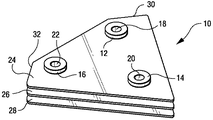
まず、図1〜図3を参照すると、断熱装置10は3つの別個の柱状部12、14及び16から構成され、各柱状部には貫通孔18、20及び22がそれぞれ形成されている。複数の平坦な板24、26及び28は軸方向に互いに離間する関係で、すなわち、柱状部の長手方向軸に沿って軸方向に離間するように柱状部に固着されている。断熱装置10は、全体的に約4.11cm(1.5インチ)の高さ寸法を有する。
First, referring to FIGS. 1 to 3, the
3枚の冷却板24、26及び28の厚さは約2.74mm(0.10インチ)であり、それらを平面図で見た形状はほぼ三角形であって、角部30及び32で面取りされている。冷却板24、26及び28は、振動による構造上の条件による制限のみを受けて、エンドカバーに対して最大限のフットプリント又は有効面積を形成する。
The thickness of the three
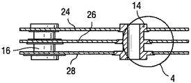
板24、26及び28は、図4に最も明瞭に示されるように、例えば、ろう付けにより、それぞれ対応する半径方向フランジ34、36及び38に固着されている。柱状部への板のろう付けを容易にするように、フランジの直径は(図3および図4に示す向きで)上から下に向かって大きくなっている。
The
柱状部12、14及び16の長さ又は高さは、伝導長さを増し、従って、燃焼器エンドカバー42から液体燃料分配弁40への熱伝達を減少させるように定められている。この実施例では、柱状部及び板を含めて、断熱装置10はステンレス鋼から製造されている。
The length or height of the
柱状部12、14及び16は、液体燃料構成部品の装着フランジ及びボルトパターンに対応するように配列されている。この実施例では、構成部品は、図5に最も明瞭に示される液体燃料分配弁40を含む。このように、装置10は、液体燃料分配弁40の装着フランジ44及び燃焼器エンドカバー42のうちのいずれかを変形することなく、それらの燃料構成部品の間に装着され、ボルト46、48及び50により固着されることが可能である。この構成によって、断熱装置10の広い平面図形領域がエンドカバー42から放射モードを遮蔽することになる。同時に、板24、26及び28の間を250〜275°Fの温度で流通する冷却空気が液体燃料分配弁40及びその弁を通って流れる燃料を冷却するという利点も得られる。燃料の温度は約50°F低下するであろうと期待される。
The
板の三角形の形状は、装着フランジ又は板が装着されるべき燃料構成部品の他の面の形状と、それに関連するボルトパターンの影響を大きく受けていることが理解されるであろう。板の形状と枚数は特定の適用用途に応じて異なるであろう。例えば、4ボルトパターンを有する分配弁に対応する正方形の装着フランジの場合には、4ボルトパターンに適応するために正方形の板及び4つの柱状部を含むように装置10を変形することが可能であろう。
It will be appreciated that the triangular shape of the plate is greatly influenced by the shape of the mounting flange or other surface of the fuel component to which the plate is to be mounted and the associated bolt pattern. The shape and number of plates will vary depending on the particular application. For example, in the case of a square mounting flange corresponding to a distribution valve having a 4-bolt pattern, the
断熱装置10の主な利点は、熱抵抗が増加し、その結果、液体燃料の温度を低下させるように液体燃料分配弁の動作温度が十分に低下し、そのために、動作効率が向上することである。断熱装置10は現在あるシステムへの追加装置として設計されているが、燃料管などの既存の構成要素の変形は最小限にとどめられる。
The main advantage of the
本発明を現時点で最も実用的で好ましい実施例であると考えられるものに関連して説明したが、本発明は開示された実施例に限定されるべきではなく、また、特許請求の範囲に記載された符号は、理解容易のためであってなんら発明の技術的範囲を実施例に限縮するものではない。 Although the present invention has been described in connection with what is presently considered to be the most practical and preferred embodiments, the present invention should not be limited to the disclosed embodiments and is described in the claims. The reference numerals are provided for easy understanding and do not limit the technical scope of the invention to the embodiments.
10…断熱装置、12、14、16…柱状部、18、20、22…貫通孔、24、26、28…板、34、36、38…フランジ、40…液体燃料分配弁、42…燃焼器エンドカバー、44…装着フランジ、46、48、50…ボルト
DESCRIPTION OF
Claims (10)
Applications Claiming Priority (1)
| Application Number | Priority Date | Filing Date | Title |
|---|---|---|---|
| US10/631,028 US7114321B2 (en) | 2003-07-31 | 2003-07-31 | Thermal isolation device for liquid fuel components |
Publications (2)
| Publication Number | Publication Date |
|---|---|
| JP2005054789A true JP2005054789A (en) | 2005-03-03 |
| JP2005054789A5 JP2005054789A5 (en) | 2007-09-13 |
Family
ID=33541505
Family Applications (1)
| Application Number | Title | Priority Date | Filing Date |
|---|---|---|---|
| JP2004223006A Pending JP2005054789A (en) | 2003-07-31 | 2004-07-30 | Thermal isolation device for liquid fuel components |
Country Status (4)
| Country | Link |
|---|---|
| US (1) | US7114321B2 (en) |
| EP (1) | EP1503145A1 (en) |
| JP (1) | JP2005054789A (en) |
| CN (1) | CN1580642A (en) |
Cited By (1)
| Publication number | Priority date | Publication date | Assignee | Title |
|---|---|---|---|---|
| JP2017524094A (en) * | 2014-07-02 | 2017-08-24 | ヌオーヴォ ピニォーネ ソチエタ レスポンサビリタ リミタータNuovo Pignone S.R.L. | Fuel distribution device, gas turbine engine, and mounting method |
Families Citing this family (9)
| Publication number | Priority date | Publication date | Assignee | Title |
|---|---|---|---|---|
| DE50212871D1 (en) * | 2001-09-07 | 2008-11-20 | Alstom Technology Ltd | DAMPING ARRANGEMENT FOR REDUCING COMBUSTION CHAMBER PULSATION IN A GAS TURBINE SYSTEM |
| US7874164B2 (en) * | 2006-11-03 | 2011-01-25 | Pratt & Whitney Canada Corp. | Fuel nozzle flange with reduced heat transfer |
| US20110016866A1 (en) * | 2009-07-22 | 2011-01-27 | General Electric Company | Apparatus for fuel injection in a turbine engine |
| US8683804B2 (en) * | 2009-11-13 | 2014-04-01 | General Electric Company | Premixing apparatus for fuel injection in a turbine engine |
| US9447970B2 (en) * | 2011-05-12 | 2016-09-20 | General Electric Company | Combustor casing for combustion dynamics mitigation |
| US20130269351A1 (en) * | 2012-04-17 | 2013-10-17 | General Electric Company | Micromixer assembly of a turbine system and method of assembly |
| WO2014152123A1 (en) * | 2013-03-14 | 2014-09-25 | United Technologies Corporation | Heatshield discourager seal for a gas turbine engine |
| CN103528094B (en) * | 2013-07-10 | 2015-04-08 | 辽宁省燃烧工程技术中心(有限公司) | Dry-type low-nitrogen combustion device for gas fuel of gas turbine |
| CN106941769B (en) * | 2016-11-16 | 2019-12-27 | 林进东 | Heat dissipation structural part with good comprehensive performance and preparation process thereof |
Citations (4)
| Publication number | Priority date | Publication date | Assignee | Title |
|---|---|---|---|---|
| GB1411110A (en) * | 1971-11-23 | 1975-10-22 | Vidalenq M | Central heating installations |
| US4008568A (en) * | 1976-03-01 | 1977-02-22 | General Motors Corporation | Combustor support |
| JPH0213703A (en) * | 1988-06-30 | 1990-01-18 | Toyota Central Res & Dev Lab Inc | Spray type burner |
| JPH02218428A (en) * | 1989-02-17 | 1990-08-31 | Jgc Corp | Multitube-type apparatus having intermediate tube sheet |
Family Cites Families (14)
| Publication number | Priority date | Publication date | Assignee | Title |
|---|---|---|---|---|
| GB441674A (en) | 1934-08-14 | 1936-01-23 | Ludwig Heuser | Improvements in heat exchange devices |
| US2690462A (en) * | 1952-02-05 | 1954-09-28 | Gen Motors Corp | Thermocouple |
| US3615054A (en) | 1965-09-24 | 1971-10-26 | Aerojet General Co | Injectors |
| US3771595A (en) | 1971-09-22 | 1973-11-13 | Modine Mfg Co | Heat exchange device |
| US4422300A (en) * | 1981-12-14 | 1983-12-27 | United Technologies Corporation | Prestressed combustor liner for gas turbine engine |
| US4502461A (en) * | 1983-04-11 | 1985-03-05 | Keating Of Chicago, Inc. | Griddle control for minimum temperature variation |
| EP0224817B1 (en) * | 1985-12-02 | 1989-07-12 | Siemens Aktiengesellschaft | Heat shield arrangement, especially for the structural components of a gas turbine plant |
| GB8805587D0 (en) | 1988-03-09 | 1988-04-07 | Batters R S | Heat radiating element |
| US5174714A (en) | 1991-07-09 | 1992-12-29 | General Electric Company | Heat shield mechanism for turbine engines |
| US5211005A (en) * | 1992-04-16 | 1993-05-18 | Avco Corporation | High density fuel injection manifold |
| US5562408A (en) | 1995-06-06 | 1996-10-08 | General Electric Company | Isolated turbine shroud |
| US5704208A (en) * | 1995-12-05 | 1998-01-06 | Brewer; Keith S. | Serviceable liner for gas turbine engine |
| US6092361A (en) | 1998-05-29 | 2000-07-25 | Pratt & Whitney Canada Corp. | Recuperator for gas turbine engine |
| US6763663B2 (en) | 2001-07-11 | 2004-07-20 | Parker-Hannifin Corporation | Injector with active cooling |
-
2003
- 2003-07-31 US US10/631,028 patent/US7114321B2/en not_active Expired - Fee Related
-
2004
- 2004-07-30 EP EP04254575A patent/EP1503145A1/en not_active Withdrawn
- 2004-07-30 CN CNA2004100588490A patent/CN1580642A/en active Pending
- 2004-07-30 JP JP2004223006A patent/JP2005054789A/en active Pending
Patent Citations (4)
| Publication number | Priority date | Publication date | Assignee | Title |
|---|---|---|---|---|
| GB1411110A (en) * | 1971-11-23 | 1975-10-22 | Vidalenq M | Central heating installations |
| US4008568A (en) * | 1976-03-01 | 1977-02-22 | General Motors Corporation | Combustor support |
| JPH0213703A (en) * | 1988-06-30 | 1990-01-18 | Toyota Central Res & Dev Lab Inc | Spray type burner |
| JPH02218428A (en) * | 1989-02-17 | 1990-08-31 | Jgc Corp | Multitube-type apparatus having intermediate tube sheet |
Cited By (3)
| Publication number | Priority date | Publication date | Assignee | Title |
|---|---|---|---|---|
| JP2017524094A (en) * | 2014-07-02 | 2017-08-24 | ヌオーヴォ ピニォーネ ソチエタ レスポンサビリタ リミタータNuovo Pignone S.R.L. | Fuel distribution device, gas turbine engine, and mounting method |
| JP2020172929A (en) * | 2014-07-02 | 2020-10-22 | ヌオーヴォ ピニォーネ ソチエタ レスポンサビリタ リミタータNuovo Pignone S.R.L. | Fuel dispensing device, gas turbine engine and attachment method |
| US11499481B2 (en) | 2014-07-02 | 2022-11-15 | Nuovo Pignone Tecnologie Srl | Fuel distribution device, gas turbine engine and mounting method |
Also Published As
| Publication number | Publication date |
|---|---|
| US7114321B2 (en) | 2006-10-03 |
| EP1503145A1 (en) | 2005-02-02 |
| CN1580642A (en) | 2005-02-16 |
| US20050022530A1 (en) | 2005-02-03 |
Similar Documents
| Publication | Publication Date | Title |
|---|---|---|
| US20030140957A1 (en) | Thermoelectric module | |
| JP2005054789A (en) | Thermal isolation device for liquid fuel components | |
| US20080104838A1 (en) | Anti-vibration support for steam generator heat transfer tubes and method for making same | |
| JP2008196319A (en) | Tube support structure of heat exchanger for egr cooler | |
| TWI810448B (en) | heat sink | |
| JP6493865B2 (en) | Device for confining energy storage devices | |
| JP2007009731A (en) | Turbine | |
| JP2016501446A (en) | Flexible thermal interface for electronics | |
| JP5653950B2 (en) | Cooling system | |
| KR100959297B1 (en) | Installation for the very long storage of products that emit a high heat flux | |
| JP2004088057A (en) | Thermoelectric module | |
| CN109186908B (en) | Cooling clamping device for high-temperature vibration test of turbine guide vane | |
| JP2003078091A (en) | Cooling heat-pipe device | |
| JP2008002393A (en) | Straightening grid for exhaust and exhaust duct with the straightening grid | |
| KR20160064162A (en) | Heat transfer pipe support structure and waste heat recovery boiler | |
| JP2011003690A (en) | Cooling device | |
| JPH0461997B2 (en) | ||
| JP2007078308A (en) | Vibration control device, and heat exchanger using it | |
| CN214736070U (en) | Limiting structure of air duct and heating bin | |
| JP6129666B2 (en) | Vapor growth apparatus and heating apparatus for vapor growth | |
| JP7133960B2 (en) | assembled fins | |
| JP7323375B2 (en) | Thermoelectric generation unit mounting device and thermoelectric generation system | |
| JPH07103675A (en) | Heat pipe type radiator | |
| JPH01296092A (en) | Parallel flow multi-tube type heat exchanger and manufacture thereof | |
| JP2023082286A (en) | Combustor |
Legal Events
| Date | Code | Title | Description |
|---|---|---|---|
| A521 | Written amendment |
Free format text: JAPANESE INTERMEDIATE CODE: A523 Effective date: 20070725 |
|
| A621 | Written request for application examination |
Free format text: JAPANESE INTERMEDIATE CODE: A621 Effective date: 20070725 |
|
| A131 | Notification of reasons for refusal |
Free format text: JAPANESE INTERMEDIATE CODE: A131 Effective date: 20091124 |
|
| A02 | Decision of refusal |
Free format text: JAPANESE INTERMEDIATE CODE: A02 Effective date: 20100420 |