JP2005046615A - Eyelet - Google Patents
Eyelet Download PDFInfo
- Publication number
- JP2005046615A JP2005046615A JP2004200079A JP2004200079A JP2005046615A JP 2005046615 A JP2005046615 A JP 2005046615A JP 2004200079 A JP2004200079 A JP 2004200079A JP 2004200079 A JP2004200079 A JP 2004200079A JP 2005046615 A JP2005046615 A JP 2005046615A
- Authority
- JP
- Japan
- Prior art keywords
- eyelet
- flange
- eyelet according
- curtain
- nail
- Prior art date
- Legal status (The legal status is an assumption and is not a legal conclusion. Google has not performed a legal analysis and makes no representation as to the accuracy of the status listed.)
- Pending
Links
Images


Classifications
-
- A—HUMAN NECESSITIES
- A47—FURNITURE; DOMESTIC ARTICLES OR APPLIANCES; COFFEE MILLS; SPICE MILLS; SUCTION CLEANERS IN GENERAL
- A47H—FURNISHINGS FOR WINDOWS OR DOORS
- A47H13/00—Fastening curtains on curtain rods or rails
- A47H13/02—Fastening curtains on curtain rods or rails by rings, e.g. with additional runners
Abstract
Description
この発明は、布地類の穴に取り付ける"ハトメ"に関する。このハトメは、カーテン掛け用の棒に通すためのカーテンの頭付けの穴に用いられるが、これに限られない。 The present invention relates to a “eyelet” that is attached to a hole in fabric. This eyelet is used for a hole in the head of the curtain for passing through a rod for curtain hanging, but is not limited thereto.
カーテン用の棒に掛けるカーテンは、通常カーテンの布地の頭付け(heading)部分に縫い付けられたか又は固定された"カーテン頭付けテープ"を有しており、このテープには一列に並んだ複数の穴が設けられている。このテープは、この一列に並んだ穴に固定された"ハトメ"を補強している。
公知の配置例をひとつ挙げる。第1のハトメ構造体が、両側に間隔のあいた複数の周辺フランジを有する環状をしており、テープ材がその複数の周辺フランジの間に挟まれるように頭付けテープの穴に予め固定されている。第2のハトメ構造体が、一方の側に周辺フランジを有する環状挿入体の形状をしている。第2のハトメ構造体が、カーテン材の各穴に押し込まれると、上記第1のハトメ構造体と噛み合って結合し、カーテン材が第2構造体の周辺フランジと第1構造体の周辺フランジとの間に挟み込まれる。
異なるカーテン材は様々な厚さを有しているため、この公知の配置には、全ての厚さのカーテン材について、上記第2のハトメ構造体が簡単に且つ確実に第1の構造体と結合することが出来ないという問題がある。
Curtains hung on curtain rods usually have "curtain heading tapes" sewn or secured to the heading part of the curtain fabric, which tapes are arranged in multiple rows. Holes are provided. This tape reinforces the "eyelet" fixed in this line of holes.
One known arrangement example is given. The first eyelet structure has an annular shape having a plurality of peripheral flanges spaced on both sides, and is fixed in advance to the hole of the head tape so that the tape material is sandwiched between the plurality of peripheral flanges. Yes. The second eyelet structure is in the form of an annular insert having a peripheral flange on one side. When the second eyelet structure is pushed into each hole of the curtain material, the second eyelet structure is engaged with and coupled with the first eyelet structure, and the curtain material has a peripheral flange of the second structure and a peripheral flange of the first structure. It is sandwiched between.
Since different curtain materials have different thicknesses, this known arrangement allows the second eyelet structure to be easily and reliably connected to the first structure for all thickness curtain materials. There is a problem that it cannot be combined.
本発明の一つの目的は、広範囲の厚さの布地の穴内に簡単且つうまい具合に取りつけることが出来るハトメを提供することである。 One object of the present invention is to provide an eyelet that can be easily and gracefully installed within a wide range of thickness fabric holes.
即ち、本発明は、布地の穴に取り付けるためのハトメであって、このハトメが第1及び第2の環状ハトメ構造体(1,9)から成り、これらの構造体がそれぞれお互いに噛み合って結合するような構成を有し、またこれらの構造体がそれぞれそれらの間に上記布地を保持するためのフランジ(5,11)を有し、更にこれらフランジが異なる間隔で噛み合って結合するような構成(4a,17a)であることを特徴とするハトメである。
このような構成であるため、このハトメは異なる厚さの布地材料に簡単に取りつけることができる。更に、このハトメ構造体は、使用するまで布地材料から完全に分離される得るため、これを使った製造を簡単に行うことが出来る。
環状ハトメ構造体に関しては、完全な環状であることが好ましいが、部分的に環状であるだけ又はその類似構造であってもよく、又周辺部も環状であることが好ましいが、必ずしも連続していなくともよい。
That is, the present invention is an eyelet for attaching to a hole in a cloth, and the eyelet is composed of first and second annular eyelet structures (1, 9), which are engaged with each other and connected. And each of these structures has flanges (5, 11) for holding the fabric between them, and these flanges are engaged with each other at different intervals. The eyelet is characterized by being (4a, 17a).
Because of this configuration, the eyelets can be easily attached to fabric materials of different thicknesses. In addition, the eyelet structure can be completely separated from the fabric material until use, so that it can be easily manufactured.
Regarding the ring eyelet structure, it is preferable that the structure is completely circular, but it may be only partially circular or a similar structure, and it is preferable that the peripheral part is also cyclic, but it is not necessarily continuous. Not necessary.
フランジに関しては、完全な周辺フランジであることが好ましく、少なくとも実質的に放射状に環状末端部にまで伸びていることが好ましい。しかし、部分的周辺フランジ又は同様形状であってもよく、不連続に放射状に末端周辺に伸びているものでもよい。
上記噛み合い構成に関しては、如何なる適当な形状を採用してもよい。一例として、第2の歯止め(ラチェット)又は多段の階段状部品に設けられた1又はそれ以上の突起及び/又は溝と結合可能な、軸方向に間隔の空いた溝及び/又は突起又は爪を有する第1の歯止め(ラチェット)又は多段の階段状部品、又はその他の協働構造体から成る構成を挙げることができる。
With respect to the flange, it is preferably a complete peripheral flange and preferably extends at least substantially radially to the annular end. However, it may be a partial peripheral flange or similar shape, or it may be discontinuously extending radially around the distal end.
Any suitable shape may be adopted for the meshing configuration. As an example, axially spaced grooves and / or protrusions or claws that can be coupled with one or more protrusions and / or grooves provided on a second ratchet or multi-step stepped part. A configuration comprising a first pawl having a ratchet or a multi-stage stepped component or other cooperating structure may be mentioned.
この構成に加えて、これらの構造体の位置保持を助けるための、例えば、布地材料に対する相対的回転を防止するための保持手段(7a)を有してもよい。このような構成において、一方の構造体が1若しくはそれ以上の突起した針又は釘を有し、これが他方の構造体に設けられた1若しくはそれ以上の受け穴、くぼみ又は溝と協働し、使用時にはこの針や釘が布地材料を貫通するように配置される。
このような針又は釘が、ハトメ構造体の一方のフランジ上に設けられ、これら受け穴、くぼみ又は溝が他方のフランジ上に設けられてもよい。
一つの実施態様において、一方のフランジに円周方向に複数の針又は釘が間隔を空けて設けられ、これらが他方のフランジ上に円周方向に配列した溝と協働してもよい。
In addition to this configuration, it may have holding means (7a) to help maintain the position of these structures, for example to prevent relative rotation with respect to the fabric material. In such a configuration, one structure has one or more protruding needles or nails that cooperate with one or more receiving holes, indentations or grooves provided in the other structure; In use, the needle or nail is arranged to penetrate the fabric material.
Such needles or nails may be provided on one flange of the eyelet structure, and these receiving holes, indentations or grooves may be provided on the other flange.
In one embodiment, one flange may be provided with a plurality of circumferentially spaced needles or nails that cooperate with grooves circumferentially arranged on the other flange.
特に好ましい態様においては、各構造体が、その一端に放射状に伸びるフランジと結合したチューブ状部分を有し、その他端に自由突起物(釘等)を有し、チューブ状部分が噛み合い構成となっており、この一つのチューブ状部分が他方のチューブ状部分の中に軸状にはめ込まれる。
各フランジは放射状の壁とその外周囲に内曲がりの縁とを有する"ふた(cap)"の形状をしている。
In a particularly preferred embodiment, each structure has a tube-like portion coupled to a radially extending flange at one end thereof, a free projection (eg, a nail) at the other end, and the tube-like portion is engaged. The one tubular portion is fitted into the other tubular portion in a shaft shape.
Each flange is in the shape of a “cap” having a radial wall and an inner curved edge around its outer periphery.
この2つのハトメ構造体は、それぞれプラスチック製の一体成形部品であってもよく、これらは如何なる適当な色や肌合いの材料から形成されたものであってもよい。
本発明のハトメは、カーテン頭付けに用いられてもよい。例えば、カーテン掛け棒を受け入れるための、カーテン頭付けテープとこのテープが取付けられたカーテン材料を貫通する一列に並んだ穴に用いられてもよい。これらは特に現在出願中の我々の特許出願に記載されている。
しかし、本発明はこの例に限定されない。このハトメは如何なる適当な織物やその他の布地材料に適当な目的で用いることができる。
Each of the two eyelet structures may be an integrally molded part made of plastic, and these may be formed of any appropriate color and texture material.
The eyelet of the present invention may be used for curtain heading. For example, it may be used in a line of holes through a curtain head tape and a curtain material to which the tape is attached to receive a curtain rod. These are described in particular in our currently pending patent application.
However, the present invention is not limited to this example. This eyelet can be used for any suitable woven or other fabric material for a suitable purpose.
以下、本発明を図面を用いて例証する。
図1と図2は、本発明のハトメの一形態の第1及び第2構造体の透視図である。図3〜6は組み合わされたハトメの断面図とその部分拡大図である。
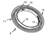
図1はハトメ構造体1を示し、一体成形されたプラスチック製リングの形状をしている。
このリングは中央に同軸の開放チューブ状部分2を有し、このチューブ状部分2は軸状平行平面3を有し、断面は環状である。
外面4は通常軸状平行であるが、環状部品の長さ方向に沿って等間隔に形成された曲線断面の同軸の溝の積層体4aを有する。
Hereinafter, the present invention will be illustrated with reference to the drawings.
1 and 2 are perspective views of first and second structures of one embodiment of the eyelet of the present invention. 3 to 6 are a cross-sectional view and a partially enlarged view of the combined eyelets.
FIG. 1 shows a
The ring has a coaxial open
The
チューブ状部分2の一端には、一体となった円周フランジ5があり、このフランジ5は連続して円形であってチューブ状部分2と同軸の外周6を有する。
フランジ5は、通常平板で放射状に広がる壁7を有し、その周囲に内側に曲がった縁8を有する。このため、フランジ5はチューブ部分2の方向に開放したふた(cap)の形状をしている。
チューブ部分2と円形同軸であるこのふた(cap)内部の規則的に配置された位置に、壁7に釘7aが一体となって取付けられており、この釘7aはチューブ部分2の方向に縁8より突起している。
At one end of the
The
A
図2は第2ハトメ構造体9を示す。図1と同様に、このハトメ構造体9は同軸の開放チューブ状部分10を有し、このチューブ状部分10は一端にフランジ11を有し、このフランジ11は平板で放射状に広がる壁12と内側に曲がった縁13を有し、その結果ふた(cap)形状をしている。
ふた(cap)13内部には、2つの同軸壁14と15があり、縁13と同じ高さであり、その結果これらの間に溝16が形成され、チューブ部分10の方向に開放している。
チューブ部分10は曲線断面の積層体17aを有し、この積層体17aはチューブ部分の溝に似ているが、チューブ部分10の内面17上に設けられている。チューブ部分10の内面18は軸状平行平面である。
第2構造体9のチューブ部分10は第1構造体1のチューブ状部分2よりも広く、即ち、チューブ部分10の内径はチューブ状部分2の外径にほぼ等しい。
FIG. 2 shows the
Inside the
The
The
図3〜6に示すように、第2構造体のチューブ状部分10の中に第1構造体1のチューブ状部分2が入って、積層体4aと積層体17aとがお互いに噛み合うように、即ち、一方の積層体の突起が他方の積層体の溝と噛み合うように、2つの構造体1,9は圧力ばめされる。
積層体4aと積層体17aとはラチェットのように機能し、そのため、2つの構造体1,9は、積層体4aと積層体17aの噛み合う突起と溝とによって決まる異なった間隔で、2つのフランジ5,11によって保持される。この2つの積層体4a,17aの突起と溝は似た断面を有し、チューブ状部分2,10の材質はわずかに弾性であるため、チューブ状部分2はチューブ状部分10の中に異なる深さではまり、強く押したり引いたりしない限り、この決められた深さで保持される。
As shown in FIGS. 3 to 6, the
The stacked
本発明のハトメが、テープとカーテン頭付けとに空けられた一列に並んだ穴のある布地製カーテン頭付けテープを有する布地製のカーテンの頭付けに用いられた場合、一方の構造体1をカーテン頭付けの穴に通してハトメ構造体を押し、かつテープの穴ごしに他方の構造体9を押しつけることによって、2つのハトメ構造体がお互いに結合する。
完全に押しこまれた場合、カーテンとテープ材料は、布地に接する縁8,11の自由端によって、2つのフランジ5,11の間にしっかりと保持される。
When the eyelet of the present invention is used for heading a fabric curtain having a fabric curtain heading tape with a line of holes in the tape and curtain heading, one
When fully indented, the curtain and tape material are held firmly between the two
この配置において、釘7aはこの布地材料を貫通して溝16に入り、その結果ハトメをこの位置に保持し、ハトメが材料に対して回転することを防止する。
この実施態様において、ハトメは、容易に製造することの出来るこのハトメとテープの構成を利用することによって、広範囲の厚さを有するカーテンとテープの中に一列に並んだ穴に容易に取付られることができる。
以上、本発明を上記実施態様を用いて例証したが、これらは単に本発明を説明するために記載されたものであり、本発明を限定することを意図するものではない。
In this arrangement, the
In this embodiment, the eyelet can be easily attached to a line of holes in a wide range of curtains and tapes by utilizing this eyelet and tape configuration that can be easily manufactured. Can do.
Although the present invention has been illustrated using the above-described embodiments, these have been described merely to illustrate the present invention and are not intended to limit the present invention.
1 第1環状ハトメ構造体
2,10 チューブ状部分
4a,17a 積層体(噛み合い構成)
5,11 フランジ
7a 突起物(針又は釘)
8,11 縁
9 第2環状ハトメ構造体
16 溝
DESCRIPTION OF
5,11
8, 11
Claims (11)
11. An assembly comprising a curtain head attached with a curtain head tape and a plurality of aligned holes pierced through the curtain head tape and the tape; An assembly to which a plurality of eyelets according to any one of the above items are attached.
Applications Claiming Priority (1)
| Application Number | Priority Date | Filing Date | Title |
|---|---|---|---|
| GB0316020A GB2403784B (en) | 2003-07-08 | 2003-07-08 | Eyelets |
Publications (2)
| Publication Number | Publication Date |
|---|---|
| JP2005046615A true JP2005046615A (en) | 2005-02-24 |
| JP2005046615A5 JP2005046615A5 (en) | 2007-07-19 |
Family
ID=27741838
Family Applications (1)
| Application Number | Title | Priority Date | Filing Date |
|---|---|---|---|
| JP2004200079A Pending JP2005046615A (en) | 2003-07-08 | 2004-07-07 | Eyelet |
Country Status (3)
| Country | Link |
|---|---|
| EP (1) | EP1498055A3 (en) |
| JP (1) | JP2005046615A (en) |
| GB (1) | GB2403784B (en) |
Cited By (4)
| Publication number | Priority date | Publication date | Assignee | Title |
|---|---|---|---|---|
| KR101139106B1 (en) | 2012-01-12 | 2012-04-30 | 이성환 | Eyelet |
| KR101357229B1 (en) | 2013-12-12 | 2014-02-04 | 이성환 | Combination type ornamentand and methods for manufacturing a ornamentand |
| US9273707B2 (en) | 2014-01-07 | 2016-03-01 | Seong Hwan Lee | Female-male combination type ornament |
| KR101753096B1 (en) | 2016-05-23 | 2017-07-03 | 김양순 | Metal eyelet |
Families Citing this family (3)
| Publication number | Priority date | Publication date | Assignee | Title |
|---|---|---|---|---|
| FR2892007B1 (en) * | 2005-10-14 | 2007-12-21 | Daniel Vedrenne | EARLY READY TO APPLY FOR CURTAIN |
| GB2451426A (en) * | 2007-07-20 | 2009-02-04 | Sarbjit Singh Bhamra | A protective fitment for an aperture in sheet metal |
| EP2226139B1 (en) * | 2009-03-07 | 2016-09-28 | SMS Concast AG | Continuous casting method and device for creating preliminary forms, in particular double-t preliminary forms |
Citations (3)
| Publication number | Priority date | Publication date | Assignee | Title |
|---|---|---|---|---|
| JPS5483904A (en) * | 1977-12-19 | 1979-07-04 | Matsushita Electric Ind Co Ltd | Methane gas producer |
| JPS6177806A (en) * | 1984-09-25 | 1986-04-21 | Mitsubishi Rayon Co Ltd | Light transmittable fiber |
| JP2002193016A (en) * | 2000-12-27 | 2002-07-10 | Nippon Pop Rivets & Fasteners Ltd | Fixture for mat |
Family Cites Families (6)
| Publication number | Priority date | Publication date | Assignee | Title |
|---|---|---|---|---|
| GB1152082A (en) * | 1966-06-07 | 1969-05-14 | Sabino Silvestre | Improved Device for Hanging and Gathering Slidable Curtains |
| JPS635548Y2 (en) * | 1984-10-26 | 1988-02-16 | ||
| US5769144A (en) * | 1996-09-04 | 1998-06-23 | Carter; Damon A. | Eyelet reinforcement for curtains |
| DE29800419U1 (en) * | 1998-01-13 | 1998-04-23 | Nodeko Gmbh Handels Und Vertri | Hole surround |
| DE19942550A1 (en) * | 1999-09-07 | 2001-03-08 | Nodeko Gmbh Handels Und Vertri | Device for wrinkling on a curtain, a curtain or the like |
| DE20021737U1 (en) * | 2000-12-21 | 2001-06-13 | Wohntextil Friesen Gmbh | Hole surround |
-
2003
- 2003-07-08 GB GB0316020A patent/GB2403784B/en not_active Expired - Fee Related
-
2004
- 2004-07-06 EP EP04254037A patent/EP1498055A3/en not_active Withdrawn
- 2004-07-07 JP JP2004200079A patent/JP2005046615A/en active Pending
Patent Citations (3)
| Publication number | Priority date | Publication date | Assignee | Title |
|---|---|---|---|---|
| JPS5483904A (en) * | 1977-12-19 | 1979-07-04 | Matsushita Electric Ind Co Ltd | Methane gas producer |
| JPS6177806A (en) * | 1984-09-25 | 1986-04-21 | Mitsubishi Rayon Co Ltd | Light transmittable fiber |
| JP2002193016A (en) * | 2000-12-27 | 2002-07-10 | Nippon Pop Rivets & Fasteners Ltd | Fixture for mat |
Cited By (6)
| Publication number | Priority date | Publication date | Assignee | Title |
|---|---|---|---|---|
| KR101139106B1 (en) | 2012-01-12 | 2012-04-30 | 이성환 | Eyelet |
| KR101357229B1 (en) | 2013-12-12 | 2014-02-04 | 이성환 | Combination type ornamentand and methods for manufacturing a ornamentand |
| US9273707B2 (en) | 2014-01-07 | 2016-03-01 | Seong Hwan Lee | Female-male combination type ornament |
| KR101753096B1 (en) | 2016-05-23 | 2017-07-03 | 김양순 | Metal eyelet |
| WO2017204432A1 (en) * | 2016-05-23 | 2017-11-30 | 김양순 | Metal eyelet |
| CN108135333A (en) * | 2016-05-23 | 2018-06-08 | 金良顺 | Grommet |
Also Published As
| Publication number | Publication date |
|---|---|
| GB2403784A (en) | 2005-01-12 |
| EP1498055A2 (en) | 2005-01-19 |
| GB2403784B (en) | 2006-05-03 |
| GB0316020D0 (en) | 2003-08-13 |
| EP1498055A3 (en) | 2006-02-08 |
Similar Documents
| Publication | Publication Date | Title |
|---|---|---|
| US4562624A (en) | Snap fastener for use on garments | |
| USD870147S1 (en) | Display screen or portion thereof with icon | |
| USD849053S1 (en) | Display screen or portion thereof with icon | |
| USD849049S1 (en) | Display screen or portion thereof with icon | |
| JP7085769B2 (en) | Snap button | |
| US3210820A (en) | One-way snap fastener combination | |
| USD851682S1 (en) | Display screen or portion thereof with icon | |
| US20160186789A1 (en) | Magnetic Closure System | |
| JP2005046615A (en) | Eyelet | |
| US20160238060A1 (en) | Vacuum absorber | |
| US20150296910A1 (en) | Magnetic closure system | |
| USD942999S1 (en) | Display screen or portion thereof with icon | |
| EP2390518A1 (en) | Suction cup assembly | |
| JP4357394B2 (en) | Attachment body to panel hole and clamp | |
| US10485307B2 (en) | Fastening device and fastening system | |
| JP2011231871A (en) | Attaching structure | |
| JP2009072329A (en) | Hook implement | |
| USD888595S1 (en) | Smoke detector | |
| JP2007175425A (en) | Cap for button, fastener and button | |
| JP6413160B2 (en) | Suture lock member and suture needle set | |
| JP2005046615A5 (en) | ||
| JP6826384B2 (en) | Fastener | |
| JPWO2009116615A1 (en) | Retaining ring | |
| US1156231A (en) | Button-fixture. | |
| JP3034077U (en) | Decorative tack and hook button |
Legal Events
| Date | Code | Title | Description |
|---|---|---|---|
| A521 | Written amendment |
Free format text: JAPANESE INTERMEDIATE CODE: A523 Effective date: 20070605 |
|
| A621 | Written request for application examination |
Free format text: JAPANESE INTERMEDIATE CODE: A621 Effective date: 20070605 |
|
| A131 | Notification of reasons for refusal |
Effective date: 20100616 Free format text: JAPANESE INTERMEDIATE CODE: A131 |
|
| A601 | Written request for extension of time |
Free format text: JAPANESE INTERMEDIATE CODE: A601 Effective date: 20100916 |
|
| A602 | Written permission of extension of time |
Effective date: 20100922 Free format text: JAPANESE INTERMEDIATE CODE: A602 |
|
| A601 | Written request for extension of time |
Free format text: JAPANESE INTERMEDIATE CODE: A601 Effective date: 20101015 |
|
| A521 | Written amendment |
Effective date: 20101020 Free format text: JAPANESE INTERMEDIATE CODE: A523 |
|
| A602 | Written permission of extension of time |
Free format text: JAPANESE INTERMEDIATE CODE: A602 Effective date: 20101020 |
|
| A02 | Decision of refusal |
Free format text: JAPANESE INTERMEDIATE CODE: A02 Effective date: 20110905 |