JP2005023705A - Structure - Google Patents
Structure Download PDFInfo
- Publication number
- JP2005023705A JP2005023705A JP2003192359A JP2003192359A JP2005023705A JP 2005023705 A JP2005023705 A JP 2005023705A JP 2003192359 A JP2003192359 A JP 2003192359A JP 2003192359 A JP2003192359 A JP 2003192359A JP 2005023705 A JP2005023705 A JP 2005023705A
- Authority
- JP
- Japan
- Prior art keywords
- steel pipe
- column
- joined
- gusset plate
- steel
- Prior art date
- Legal status (The legal status is an assumption and is not a legal conclusion. Google has not performed a legal analysis and makes no representation as to the accuracy of the status listed.)
- Granted
Links
Images


Landscapes
- Joining Of Building Structures In Genera (AREA)
Abstract
Description
【0001】
【発明の属する技術分野】
本発明は、柱と梁とが備えられている構造物に関する。
【0002】
【従来の技術】
近年、制震ダンパー等のブレースを鉄筋コンクリート造構造物の柱と梁とで形成された架構内に組み入れることで、鉄筋コンクリート造構造物の地震時応答変位を低減し、変形性能の劣る鉄筋コンクリート造構造物の損傷を軽減させる構造物が提案されている。一般的に、ブレースは鋼構造の架構内に組み入れ、鋼製接合部(ガセットプレート)に接合されている。したがって、従来、鉄筋コンクリート構造の架構内にブレースを組み入れる場合には、ブレースを組み入れる架構を形成する梁或いはブレースを組み入れる架構を鉄骨構造や鉄骨鉄筋コンクリート構造にする方法、或いは柱側面に添柱を接合してこの添柱に鋼製接合部(ガセットプレート)を接合する方法が提案されている。
【0003】
前者の従来の方法は、ブレースが組み入れられる架構を形成する柱や梁に鉄骨材を設け、この鉄骨材にブレースが接合されるガセットプレートを溶接する方法である。この方法によれば、鉄骨材によって鋼構造の架構或いは梁が形成され、架構の上辺を形成する梁鉄骨の中央下部にガセットプレートが垂設されるとともに、架構の下両隅部にガセットプレートがそれぞれ設けられる。これによって、架構内に斜めに延在するブレースを組み入れることができる(例えば、特許文献1参照。)。
【0004】
後者の従来の方法は、鉄筋コンクリート造の柱の側面に添柱がスタッドなどで接合され、この添柱にガセットプレートが接合されるとともに梁から突設するガセットプレートが梁中央に埋め込まれている方法である。この方法によれば、柱および梁が鉄筋コンクリート構造となり、施工コストを低減することができるとともに、高軸力に対応することができる。
【0005】
【特許文献1】
特開2000−213201号公報 (第3−5頁、第2図)
【0006】
【発明が解決しようとする課題】
しかしながら、上記した前者の従来の方法では、柱主筋や柱フープ筋等の鉄筋材が柱と梁との仕口部内で梁の鉄骨材に干渉するため、柱主筋や柱フープ筋の配筋作業が難しくなり手間がかかるという問題が存在する。また、架構を形成する際に鉄骨材を組み入れる作業が必要となり、工期延長の要因となるとともに施工コストが嵩むという問題が存在する。
【0007】
また、上記した後者の従来の方法では、仕口部が、鉄筋コンクリート構造となり、変形性能に劣り、曲げや剪断力に対してひび割れや破壊が生じ易い(靭性に劣る)という問題が存在する。特に仕口部に引張り軸力が作用する場合には、仕口部の剪断耐力は更に低下するという問題が存在する。
【0008】
本発明は、上記した従来の問題を考慮したものであり、柱主筋や柱フープ筋等の鉄筋材の干渉を防止して施工を容易にすることができる構造物を提供することを目的としている。また、高軸力に対応するとともに曲げや剪断力に抵抗する仕口部を形成することで、耐力と変形性とに優れた構造物を提供することを目的としている。
【0009】
【課題を解決するための手段】
請求項1記載の発明は、間隔をあけて立設された鉄筋コンクリート造の複数の柱と、隣り合う該柱の間に上下に間隔をあけて架設された複数の梁とが備えられている構造物において、前記柱と前記梁とが接合される仕口部の外周には、前記柱と同軸上に延在する中空の鋼管が巻かれ、該鋼管内には鉛直方向に延在する複数の柱主筋が挿通されているとともに充填コンクリートが打設されていることを特徴としている。
【0010】
このような特徴により、仕口部は、柱主筋が埋設された充填コンクリートを鋼管で巻いている構成からなり、柱主筋が他の部材に干渉することはない。また、仕口部が鋼管によって補強されているため、仕口部の剪断耐力は大きく増大する。
【0011】
請求項2記載の発明は、請求項1記載の構造物において、前記柱は、複数のプレキャストコンクリート柱部材が該柱の軸方向に連続的に接合されて形成され、連続する複数の該プレキャストコンクリート柱部材は、上下で対向する前記梁の間隔である階高の中央で接合されることを特徴としている。
【0012】
このような特徴により、仕口部の直上或いは直下に比べて曲げ応力が小さく、プレキャストコンクリート柱部材の接合箇所での曲げ耐力が小さくてもよい階高の中央で、上下のプレキャストコンクリート柱部材は接合される。
【0013】
請求項3記載の発明は、請求項1または2記載の構造物において、前記鋼管は前記仕口部から該仕口部の上方または下方のうち少なくとも一方にかけて形成されていることを特徴としている。
【0014】
このような特徴により、仕口部のみならず仕口部の上方または下方の柱も鋼管で補強される。
【0015】
請求項4記載の発明は、請求項3記載の構造物において、隣り合う前記柱と上下で対向する前記梁とによって形成された架構フレーム内には、斜めに延在するブレースが配置され、前記仕口部の上方或いは下方のうち少なくとも一方の前記鋼管には、前記梁の上方或いは下方のうち少なくとも一方に配置されて前記ブレースの端部が接合されるガセットプレートが接合されていることを特徴としている。
【0016】
このような特徴により、構造物はブレースによって耐震性が向上する。また、ブレースは鋼管に接合されたガセットプレートに接合され、ブレース軸力はガセットプレートから鋼管を介して柱に伝達される。
【0017】
請求項5記載の発明は、請求項3または4記載の構造物において、前記仕口部の上方或いは下方のうち少なくとも一方の前記鋼管内には、鉛直方向に延在する補強リブプレートが接合されていることを特徴としている。
【0018】
このような特徴により、柱の軸力によって発生する鋼管の外側への膨らみは、補強リブプレートによって抑制される。
【0019】
請求項6記載の発明は、請求項1から5のいずれか記載の構造物において、前記ガセットプレートは、前記梁の上方或いは下方のうち少なくとも一方から該梁内に形成され、該梁には該梁の軸方向に延在する梁鉄骨材が備えられ、該梁鉄骨材の端部は前記梁内の前記ガセットプレートに接合されることを特徴としている。
【0020】
このような特徴により、梁鉄骨材は仕口部内に貫入されることなく柱間に架設され、柱主筋と梁鉄骨材とが干渉することはない。
【0021】
請求項7記載の発明は、請求項6記載の構造物において、前記鋼管内には水平に延在する第1のずれ止め部材が設けられ、該第1のずれ止め部材は、該鋼管の内側面、前記補強リブプレート、または前記鋼管内の前記ガセットプレートのうち少なくとも一方に接合されていることを特徴としている。
【0022】
このような特徴により、充填コンクリート内には第1のずれ止め部材が埋設され、鋼管と充填コンクリートとは、ずれることなく一体性が確保される。
【0023】
請求項8記載の発明は、請求項1から7のいずれか記載の構造物において、前記梁には前記鋼管に当接する梁コンクリートが備えられ、該梁コンクリートが当接する該鋼管の外側面には、該外側面に沿って水平に延在する第2のずれ止め部材が接合されていることを特徴としている。
【0024】
このような特徴により、柱と梁との接合面の剪断耐力が確保され、梁端部の剪断力に対抗される。
【0025】
請求項9記載の発明は、請求項1から8のいずれかに記載の構造物において、前記仕口部内には前記梁の軸方向に延在する筒状の鞘管が配置され、該鞘管内には該仕口部を貫通する前記梁の梁主筋の端部が挿通され、該梁主筋の端部には前記鋼管を両側から挟み込む複数のナットが螺合されていることを特徴としている。
【0026】
このような特徴により、梁主筋は仕口部の充填コンクリート内に埋設された鞘管内にコンクリート硬化後に挿入され、螺合された2つのナットが鋼管にそれぞれ圧接されることで梁主筋は固定される。
【0027】
【発明の実施の形態】
以下、本発明に係る構造物の第1、第2の実施の形態について、図面に基いて説明する。
【0028】
[第1の実施の形態]
まず、第1の実施の形態について説明する。図1は本発明に係る構造物1の立面図である。
【0029】
図1に示すように、構造物1には、間隔をあけて立設された複数の柱2と、隣り合う柱2の間に架設された複数の梁3と、隣り合う柱2と上下で対向する梁3とで形成された架構フレーム4内に斜めに配置されたブレース5とがそれぞれ備えられている。柱2は、柱2の軸方向に連続的に接合された複数のプレキャストコンクリート構造からなるPC柱部材6から形成されており、梁3は現場打ちの鉄筋コンクリート構造から形成されている。
【0030】
連続する複数のPC柱部材6は、上下で対向する梁3の間隔である階高Hの中央で接合されており、連続する複数のPC柱部材6中央には、柱2と梁3とが接合される仕口部7がそれぞれ形成されている。一個おきのPC柱部材6の中央にはブレース5の一端が接合される接合部8が形成されており、PC柱部材6には接合部8が備えられた第1のPC柱部材6aと接合部8が備えられていない第2のPC柱部材6bとの2種類から構成されている。
【0031】
第2のPC柱部材6bは、いずれも図示せぬ四角柱形のプレキャストコンクリートと、第2のPC柱部材6bの軸方向に延在する柱主筋および柱主筋を囲うフープ筋から構成される柱鉄筋籠とから形成されている。第2のPC柱部材6bの柱主筋の上端には図示せぬスリーブ部材が接合されており、柱主筋の下端は第2のPC柱部材6bの端面から突出されている。
【0032】
図2は接合部8が形成された第1のPC柱部材6aの断面図である。図1、図2に示すように、第1のPC柱部材6aは、接合部8と、接合部8の上下方に形成されたPC柱部材端部9とから構成されている。PC柱部材端部9は、四角柱形に成形されたプレキャストコンクリート10と、第1のPC柱部材6aの軸方向に延在する複数の柱主筋11と、複数の柱主筋11を囲うフープ筋12とから構成されている。柱主筋11およびフープ筋12は、プレキャストコンクリート10内にそれぞれ埋設されている。第1のPC柱部材6aの一端(上端)側の柱主筋11端部には筒状のスリーブ部材13が接合されており、第1のPC柱部材6aの他端(下端)側の柱主筋11端部はPC柱部材6の端面から突出されている。スリーブ部材13内には、充填材14が注入され、上方に位置する第2のPC柱部材6bの突出された柱主筋端部が挿嵌されるとともに、第1のPC柱部材6aと第2のPC柱部材6bの主筋が一体化される。
【0033】
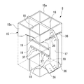
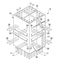
図3は接合部8の内部構造を表す斜視図であり、図4は接合部8の外形を表す斜視図である。図2、図3、図4に示すように、接合部8は、柱2の軸方向に延在する中空四角柱形の鋼管15と、上方のPC柱部材端部9から下方のPC柱部材端部9にかけて延在され鋼管15内に挿通された複数の柱主筋11と、鋼管15内に打設された充填コンクリート16と、鋼管15内から鋼管15の側方に張り出されているとともに梁3および仕口部7を上下で貫通する第1のガセットプレート17と、仕口部7の上方および下方の鋼管15内にそれぞれ配置された補強リブプレート18と、仕口部7の鋼管15内に配置された水平方向に延在する第1のずれ止め部材19と、梁3が接合される鋼管15の外側面に接合された第2のずれ止め部材20とから構成されている。
【0034】
鋼管15は、2枚のコ形鋼板15aを向かい合わせに接合して口形に形成され、2枚のコ形鋼板15aの間には第1のガセットプレート17が挟み込まれている。鋼管15の側方に張り出された第1のガセットプレート17の上下隅には、斜めに延在する斜めリブプレート36が直角に接合されている。補強リブプレート18は鋼管15内の第1のガセットプレート17に直角に接合されており、第1のガセットプレート17と補強リブプレート18とは、上視した場合の形状が十字形になるように形成されている。
【0035】
図5は第1のガセットプレート17に接合された第1のずれ止め部材19を表す断面図である。図3、図5に示すように、第1のずれ止め部材19は棒状の鉄筋材からなり、第1のずれ止め部材19は上下2本に並べられ、鋼管15内の第1のガセットプレート17を挟んで2組設けられている。複数の第1のずれ止め部材19は、鋼管15内の第1のガセットプレート17に沿ってそれぞれ配置され、第1のガセットプレート17の両面にそれぞれフレア溶接されている。
【0036】
図2、図4に示すように、梁3が接合される鋼管15の外側面に接合された第2のずれ止め部材20は、L形アングル(山形鋼)からなり、上下2本に並べられ、鋼管15外の第1のガセットプレート17を挟んで2組設けられている。第2のずれ止め部材20の両側部は鋼管15の外側面に当接されて隅肉溶接されている。また、梁3が接合される鋼管15の外側面、および鋼管15内の第1のガセットプレート17には複数の貫通孔37がそれぞれ形成されており、この貫通孔37には梁3の梁主筋38が挿通されている。
【0037】
図6は梁3を表す側面図である。図1、図6に示すように、梁3は、隣り合う鋼管15からそれぞれ水平に突出されて対向する複数の梁主筋38と、梁主筋38を囲う複数のスタラップ筋39と、対向する梁主筋38を接続する添え筋40とが現場打ちの梁コンクリート41内に埋設されている構成からなっている。対向する梁主筋38は梁3の中央部で接続されており、梁主筋38と添え筋40とは重ね合わされている。また、複数のスタラップ筋39は所定の間隔をあけて配置されている。
【0038】
図1に示すように、第1のガセットプレート17の斜め上方、或いは斜め下方に位置する梁3の中央には、下端両隅がカットされブレース5の他端が接合される第2のガセットプレート21が設けられている。第2のガセットプレート21は、梁3の上方から下方にかけて梁3を貫通して形成され、梁3の上面および下面からそれぞれ突出されている。梁3の上下面から突出する第2のガセットプレート21の上下端には、梁3の上下面に接して水平方向に延在する水平スチフナ22と、2本平行に配置されている鉛直方向に延在する縦リブプレート23とが付設されている。また、第2のガセットプレート21の四隅には、第2のガセットプレート21の下端両隅から第2のガセットプレート21の中央点に向けて斜めに延在する斜めリブプレート24が直角に接合されている。
【0039】
図7はブレース5を表す平面図であり、図8はブレース5の断面図である。図7、図8に示すように、ブレース5は、芯材25と、芯材25を囲むように設けられた筒状の補剛体26とを備えた構成となっている。芯材25は、低降伏点鋼によって形成されており、その降伏応力度は、通常の本体鉄骨以下のものとなっている。芯材25は中央部25aが両端部25bより幅が狭まった形状のものであり、芯材25の両端部25bには軸方向に延在するリブプレート27が直角にそれぞれ溶接されている。
【0040】
補剛体26は、二つの溝形鋼28のフランジ28a同士をカバープレート(鋼板)29とツヅリボルト30によってそれぞれ接合し、内部に断面視矩形状の閉鎖空間31を形成するようにしたものである。これら溝形鋼28およびツヅリボルト30は、芯材25に比較して降伏応力度の大きい鋼材により形成されている。二つの溝形鋼28の中間部には、軸方向と直交する方向に延在するリブプレート32が中央およびその両側に間隔をあけてそれぞれ溶接されており、間隔をあけて配置されたリブプレート32の間には軸方向に延在するリブプレート33がそれぞれ溶接されている。
【0041】
閉鎖空間31には、芯材25の中央部25aが挿通されており、補剛体26と芯材25の中央部25aとの間には、ゴムパッキン(押圧材)34が、板状に形成された芯材25の両面に接するように配置されている。ゴムパッキン34は、補剛体26の長さ寸法と略同一の長さ寸法を有するものとされており、芯材25は、このゴムパッキン34を介して補剛体26側から均等に押圧されている。
【0042】
図1、図7に示すように、芯材25の両端部25bは、スプライスプレート35を介して第1のガセットプレート17または第2のガセットプレート21にそれぞれ高力ボルトにより2面摩擦接合されており、芯材25の両端部25bに設けられたリブプレート27は、第1のガセットプレート17に設けられた斜め方向に延在する斜めリブプレート36、または第2のガセットプレート21に設けられた斜め方向に延在する斜めリブプレート24にスプライスプレート35を介してそれぞれ高力ボルトにより2面摩擦接合されている。
【0043】
次に、上記した構成からなる構造物1の施工方法について説明する。
【0044】
予め、図2、図3、図4に示すように、工場等にて、接合部8が備えられた第1のPC柱部材6aを製作する。矩形板からなる第1のガセットプレート17の上下隅部の両面に斜めリブプレート36を直角にそれぞれ接合するとともに、第1のガセットプレート17の上下端部の両面に補強リブプレート18を直角にそれぞれ接合する。また、第1のガセットプレート17の中央部の両面に第1のずれ止め部材19をそれぞれフレア溶接によって接合するとともに、第1のガセットプレート17の中央部に梁主筋38が挿通される貫通孔37をあける。
【0045】
次に、2枚のコ形鋼板15aを第1のガセットプレート17を挟んで向かい合わせに設置し、2枚のコ形鋼板15aの端部と第1のガセットプレート17とを接合するとともに、コ形鋼板15aの中央部と補強リブプレート18の端部とを接合し、口形の鋼管15を形成する。鋼管15には梁主筋38が挿通される貫通孔37をあけるとともに、梁3が接合される鋼管15の外側面に第2のずれ止め部材20を接合する。
【0046】
次に、鋼管15内に複数の柱主筋11を挿通させるとともに、複数の貫通孔37に梁主筋38をそれぞれ挿通させる。このとき、鋼管15から突出した各々の柱主筋11の一端(上端)にスリーブ部材13を接合するとともに柱主筋11周りにフープ筋12を配筋し、鋼管15から突出した他端(下端)の柱主筋11周りにフープ筋12を配筋する。
【0047】
次に、鋼管15から突出した柱主筋11および該柱主筋11周りに配筋されたフープ筋12を囲うように、鋼管15の上方および下方に筒状の図示せぬ柱形枠を建て込む。そして、図示せぬ柱形枠内および鋼管15内にコンクリートを打設して、PC梁部材端部9のプレキャストコンクリート10を形成するとともに接合部8の充填コンクリート16を形成する。このとき、プレキャストコンクリート10は、スリーブ部材13の上端がPC梁部材端部9の端部と面一になるように形成し、また柱主筋11の下端がPC梁部材端部の端面から突出するように形成する。
【0048】
また、予め工場等にて、第1のPC柱部材6aに連結される第2のPC柱部材6bを製作する。一方向に延在する複数の柱主筋をフープ筋で囲み、柱鉄筋籠を組み立てる。そして、この柱鉄筋籠の周りを図示せぬ柱形枠を建て込み、該柱方枠内にコンクリートを打設してプレキャストコンクリートを形成し、第2のPC柱部材6bを製作する。
【0049】
次に、上記した方法によって製作された第1のPC柱部材6aと第2のPC柱部材6bとを現場に搬入し、第1のPC柱部材6aと第2のPC柱部材6bとを交互に接合して柱2を形成する。また、隣り合おう2本の柱2の間に現場打ち鉄筋コンクリート造の梁3を形成する。
【0050】
図1、図2に示すように、第1のPC柱部材6aを第2のPC柱部材6bの上方に配置する。そして、第2のPC柱部材6bの上端部内に埋設された図示せぬスリーブ部材内に充填材を注入し、第1のPC柱部材6aの下端から突出されている複数の柱主筋11の端部を第2のPC柱部材6bの上端部内に埋設された図示せぬスリーブ部材内に挿嵌して固定する。
【0051】
次に、図1、図6に示すように、隣り合う第1のPC柱部材6aの接合部8の間に梁3を形成する。隣り合う柱2の鋼管15外側面からそれぞれ突出して対向する複数の梁主筋38を添え筋40によってそれぞれ接続し、複数の梁主筋38の周りに複数のスタラップ筋39を配筋する。複数のスタラップ筋39は、複数の梁主筋38を囲うように形成し、所定の間隔をあけて配筋する。そして、図示せぬ梁形枠を梁主筋38およびスタラップ筋39の周りに建て込み、この梁形枠内にコンクリートを打設して梁コンクリート41を形成する。
【0052】
次に、図1、図7に示すように、柱2と梁3とで形成された架構フレーム4内にブレース5を設置する。鋼管15の外側に張り出された第1のガセットプレート17と梁3の中央に埋め込まれた第2のガセットプレート21との間にブレース5を配置する。第1のガセットプレート17側に向けられたブレース5の一端部は、スプライスプレート35を介して第1のガセットプレート17に接合する。突き合わされた芯材25の端部25bと第1のガセットプレート17とを2枚のスプライスプレート35で挟み込み、スプライスプレート35と芯材25の端部25bおよびスプライスプレート35と第1のガセットプレート17とを高力ボルトによってそれぞれ2面摩擦接合する。
【0053】
また、突き合わされた芯材25の端部25bに設けられたリブプレート27と第1のガセットプレート17に設けられた斜め方向に延在する斜めリブプレート36とを突き合わせるとともに2枚のスプライスプレート35で挟み込む。そして、スプライスプレート35と端部25bに設けられたリブプレート27、およびスプライスプレート35と斜めリブプレート36とを高力ボルトによってそれぞれ2面摩擦接合する。
【0054】
また、第2のガセットプレート21側に向けられたブレース5の他端部は、スプライスプレート35を介して第2のガセットプレート21に接合する。突き合わされた芯材25の端部25bと第2のガセットプレート21とを2枚のスプライスプレート35で挟み込み、スプライスプレート35と芯材25の端部25b、およびスプライスプレート35と第2のガセットプレート21とを高力ボルトによってそれぞれ2面摩擦接合する。また、突き合わされた芯材25の端部25bに設けられたリブプレート27と第2のガセットプレート21に設けられた斜め方向に延在する斜めリブプレート24とを2枚のスプライスプレート35で挟み込む。そして、スプライスプレート25と芯材25の端部25bに設けられたリブプレート27、および10、スプライスプレート25と斜めリブプレート24とを高力ボルトによってそれぞれ2面摩擦接合する。
【0055】
上記した構成からなる構造物1によれば、仕口部7の外周には鋼管15が巻かれ、鋼管15内には柱主筋11が挿通されているとともに充填コンクリート16が打設されているため、柱主筋11が他の部材に干渉することはなく、また仕口部7内にフープ筋が配筋されない。これによって、柱主筋11と梁主筋38とが交差する仕口部7内の配筋作業を容易にすることができる。また、仕口部7は鋼管15によって補強されているため、仕口部7の剪断耐力は大きく増大する。これによって、仕口部7に引張り軸力が生じた場合にも所定の剪断耐力は確保され、構造物1を耐力と変形性能に優れたものとすることができる。
【0056】
また、柱2は第1のPC柱部材6aと第2のPC柱部材6bとが交互配置され、連続的に階高Hの中央で接合されて形成されている。階高Hの中央の柱2は、仕口部7の直上或いは直下の柱2に比べて曲げ応力が小さくなるため、階高Hの中央で接合された場合の接合箇所での曲げ耐力は小さくてよい。これによって、上下の第1のPC柱部材6aと第2のPC柱部材6bとを接合する際の、接合構造を軽減することができ、コストダウンを図ることができる。
【0057】
また、鋼管15は仕口部7から仕口部7の上方および下方にかけて形成されているため、仕口部7のみならず仕口部7の上方および下方の柱2も鋼管15で補強される。これによって、耐力と変形性とがより優れた構造物1にすることができる。
【0058】
また、架構フレーム4内にはブレース5が配置され、鋼管15にはブレース5の端部が接合される第1のガセットプレート17が接合されているため、構造物1はブレース5によって耐震性が向上されるとともに、ブレース5は鋼管15に接合された第1のガセットプレート17に接合され、ブレース5の軸力は第1のガセットプレート17から鋼管15を介して柱2に確実に伝達される。これによって、構造物1は地震時の変形性能を向上させることができる。
【0059】
また、仕口部7の上方および下方の鋼管15内には補強リブプレート18が接合されているため、柱2の軸力によって発生する鋼管15の外側への膨らみは、補強リブプレート18によって抑制される。これによって、柱2に高軸力が作用する場合、例えば高層建物における下階の柱にも適用することができる。
【0060】
また、鋼管15内の第1のガセットプレート17には第1のずれ止め部材19が接合されているため、充填コンクリート16内には第1のずれ止め部材19が埋設され、鋼管15と充填コンクリート16との一体性は確保される。これによって、ずれ止め部材19と接する充填コンクリート16の支圧により、梁3およびブレース5からの鉛直方向の軸力を柱2に円滑に伝達することができる。
【0061】
また、梁コンクリート41が当接する鋼管15の外側面には第2のずれ止め部材20が接合されているため、柱2と梁3との接合面の剪断耐力が確保され、梁3端部の剪断力に対抗される。これによって、柱2と梁3との一体性を確保することができ、鋼管15と梁コンクリート41とが分断されることを防止することができる。
【0062】
また、ブレース5を接合する第1のガセットプレート17は鋼管15に接合されているため、一つの柱2から第1のガセットプレート17を多方面に複数設けることができ、ブレース5を多方面に設置することができる。また、ブレース5の両端は高力ボルトによって2面摩擦接合されているため、ブレース5の長さ誤差に対して容易に対応することができる。また、柱2を構成するPC柱部材6は予め工場で製作されるため、寸法精度や品質管理を向上させることができるとともに、工期短縮を図ることができる。
【0063】
また、仕口部7は鋼管17により外形が形成されているため、一般に行われる現場打ちの鉄筋コンクリート構造の場合に最も複雑となる仕口部7の形枠が省略される。これによって、施工の手間を軽減することができるとともにコストダウンを図ることができる。
【0064】
また、第1のガセットプレート17に斜めリブプレート36が直角に接合されているため、第1のガセットプレート17の面外座屈を防止することができる。さらに、第2のガセットプレート21には水平スチフナ22が直角に接合されているため、梁3の上面および下面で確実に第2のガセットプレート21の面外変位と局部座屈とを防止することができ、補剛効果を確保することができる。
【0065】
[第2の実施の形態]
次に、第2の実施の形態について説明する。図9は本発明に係る構造物100の柱101および梁102を表す側面図である。
【0066】
図9に示すように、間隔をあけて立設された複数の柱101は、柱101の軸方向に連続的に接合された複数のPC柱部材103から形成されている。隣り合う柱101の間には複数の梁102が架設されており、梁102は現場打ちの鉄骨鉄筋コンクリート構造から形成されている。また、隣り合う柱101間には斜めに延在するブレース114が配置されている。
【0067】
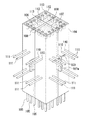
図10はPC柱部材103の断面図であり、図11はPC柱部材103の斜視図である。図10、図11に示すように、連続する複数のPC柱部材103は、柱101の軸方向に延在する中空四角柱形の鋼管104と、鋼管104内に挿通された複数の柱主筋105と、鋼管104内に打設された充填コンクリート106と、鋼管104内に設けられているとともに図9に示すブレース114の端部が接合されるガセットプレート107と、鋼管104内のガセットプレート107に直角に接合されている補強リブプレート108とから構成されている。鋼管104の製造に当っては、まず、ガセットプレート107と補強リブプレート108を十字形に溶接組立して、次いでL形に加工した4つの鋼材をとりつけることにより田形の鋼管104を形成する。
【0068】
鋼管104はPC柱部材103の全長にわたって形成されており、鋼管104は上下方向に配置されて接合されるPC柱部材103の鋼管104に当接されている。ガセットプレート107は鋼管104内に鉛直に形成されているとともに梁102内に突出する凸部107aが形成されており、凸部107aは梁102の上方から梁102内に形成されている。凸部107aの上部には斜めに延在する斜めリブプレート109が直角に接合されている。
【0069】
鋼管104内を挿通する複数の柱主筋105の上端には筒状のスリーブ部材112がそれぞれ接合されており、スリーブ部材112はその上端面が鋼管104内に打設された充填コンクリート106の上端面と面一になるように鋼管104内に配置されている。また、複数の柱主筋105の下端は、鋼管104の下端からスリーブ部材112の孔長さより短くそれぞれ突出されている。スリーブ部材112内には、充填材113が注入されるとともに上方に配置されるPC柱部材103の柱主筋105の下端が嵌入される。
【0070】
また、梁102が当接する鋼管104には複数の貫通孔110が形成されており、複数の貫通孔110には梁102の梁主筋111が挿通されている。梁102は、軸方向に延在する複数の梁主筋111と、梁主筋111に平行に配置される梁鉄骨材115と、複数の梁主筋111を囲う図示せぬ複数のスタラップ筋と、現場打ちコンクリートからなる梁コンクリート116とから構成されている。
【0071】
梁鉄骨材115の端部は梁102内に突出されたガセットプレート107の凸部107aに接合されており、梁鉄骨材115は柱101間に架設されている。ガセットプレート107の凸部107aの下部と梁鉄骨材115の端部とは、スプライスプレート117を介して高力ボルトにより2面摩擦接合されている。
【0072】
図12は梁主筋の仕口部との接合法に関する別の形態を示すもので、柱101と梁102との仕口部118を表す断面図である。図12に示すように、仕口部118内には梁102の軸方向に延在する筒状の鞘管119が複数配置されている。鞘管119は鋼管104に形成された貫通孔110の間に架設されており、鞘管119内には梁主筋111の端部が挿通されている。柱101を挟んで両側に同軸上に配置された2本の梁102の梁主筋111は一本のねじ鉄筋から形成され、梁主筋111には鋼管を両側から挟み込む複数のナット120が螺合されている。
【0073】
上記した構成からなる構造物100によれば、梁鉄骨材115の端部は鋼管104に接合されたガセットプレート107の凸部107aに接合されているため、梁鉄骨材115は仕口部118内に貫入されることなく柱101間に架設され、柱主筋105と梁鉄骨材115とは干渉することはない。これによって、梁鉄骨材115の設置作業、および柱主筋105の配筋作業を容易にすることができる。
【0074】
また、仕口部118内には鞘管119が配置され、鞘管119内には梁主筋111が挿通され、梁主筋111には鋼管104を両側から挟み込むナット120が螺合されているため、ナット120を締め付けることで梁主筋111は鋼管104に固定される。これによって、PC柱部材103を製作する際に鞘管119を埋め込んでおくことで、梁主筋111を後から配筋することができ、PC柱部材103を搬入および設置する際にPC柱部材103から突出する梁主筋111がなく、輸送効率が良く施工性を向上させることができる。また、突出した梁主筋111が作業員に接触することがないため、安全性を向上させることができる。
【0075】
また、鋼管104は柱101の全長にわたって巻き付けられているため、柱101のモーメントに対しての断面性能を向上させることができる。また、上下のPC柱部材103は階高の中央で接合されており、鋼管104同士は接合する必要はない。このため、現場での溶接作業を省略することができる。
【0076】
以上、本発明に係る構造物の実施の形態について説明したが、本発明は上記した第1、第2の実施の形態に限定されるものではなく、その趣旨を逸脱しない範囲で適宜変更可能である。例えば、上記した第1の実施の形態では梁3は鉄筋コンクリート構造であり、第2の実施の形態では鉄骨鉄筋コンクリート構造であるが、本発明は、図13に示すように、梁200を鉄骨構造としてもよい。この場合、梁200は柱201に巻き付けられた鋼管202に接合されたガセットプレート203に接合されている。
【0077】
また、上記した第1、第2の実施の形態では、梁3、102には現場打ちコンクリートからなる梁コンクリート41、116がそれぞれ備えられているが、本発明は、図14に示すように、梁300をプレキャストコンクリートからなるPC梁部材301によって形成してもよい。この場合、PC梁部材301は隣り合う柱302の間に隙間をあけて配置される。PC梁部材301の端面からは梁主筋303が突出されており、また柱302の仕口部304には梁300の軸方向に延在する梁主筋連結筋305が貫通されている。梁主筋連結筋305の両端と梁主筋303の端部とは機械式の鉄筋継手306によって接続されており、仕口部304とPC梁部材301との隙間にはコンクリート307が打設される。
【0078】
また、上記した第1の実施の形態では、第1のずれ止め部材19は鉄筋材からなり、第1のガセットプレート17にフレア溶接されているが、本発明は、図15(a)、図15(b)に示すように、平鋼からなる第1のずれ止め部材400や山形鋼からなる第1のずれ止め部材401を使用してもよい。この場合、第1のずれ止め部材400、401は第1のガセットプレート402に上下を隅肉溶接される。また、第1のずれ止め部材は第1のガセットプレート17以外にも、鋼管15の内側面や補強リブプレート18に接合してもよく、或いは鋼管15の内側面や補強リブプレート18や第1のガセットプレート17の間に架設させて接合してもよい。
【0079】
また、第2の実施の形態では、柱の全長を鋼管巻きとしたが、これは建物内の全ての柱を鋼管巻きとするのでなく、曲げや剪断応力の大きい部位を鋼管巻きとして、その他をRCとすることもできる。さらに、柱主筋は階高中央でスリーブ継手としているが、必ずしも主筋全数を継手する必要はなく、間引くことも可能である。
【0080】
【発明の効果】
以上説明したように、請求項1記載の構造物によれば、仕口部の外周には鋼管が巻かれ、鋼管内には柱主筋が挿通されているとともに充填コンクリートが打設されているため、柱主筋が他の部材に干渉することはなく、また仕口部内にフープ筋が配筋されず、柱主筋と梁主筋とが交差する仕口部内の配筋作業を容易にすることができる。また、仕口部が鋼管によって補強されているため、仕口部の剪断耐力は大きく増大し、仕口部に引張り軸力が生じた場合にも所定の剪断耐力が確保され、構造物を耐力と変形性能に優れたものとすることができる。
【0081】
また、請求項2記載の構造物によれば、柱を形成するプレキャストコンクリート柱部材は、連続的に階高Hの中央部で接合されているため、接合箇所での曲げ耐力は小さくなり、上下のプレキャストコンクリート柱部材を接合する際の、接合構造を軽減することができ、コストダウンを図ることができる。
【0082】
また、請求項3記載の構造物によれば、鋼管は仕口部から仕口部の上方または下方のうち少なくとも一方にかけて形成されているため、仕口部のみならず仕口部の上方または下方の柱も鋼管で補強され、耐力と変形性能により優れた構造物にすることができる。
【0083】
また、請求項4記載の構造物によれば、架構フレーム内にはブレースが配置され、鋼管にはブレースの端部が接合されるガセットプレートが接合されているため、構造物はブレースによって耐震性が向上するとともに、ブレースは鋼管に接合されたガセットプレートに接合され、ブレースの軸力はガセットプレートから鋼管を介して柱に確実に伝達される。これによって、構造物は地震時の変形性能を向上させることができる。
【0084】
また、請求項5記載の構造物によれば、仕口部の上方または下方のうち少なくとも一方の鋼管内には補強リブプレートが接合されているため、柱の軸力によって発生する鋼管の外側への膨らみは、補強リブプレートによって抑制され、柱に高軸力が作用する場合、例えば高層建物における下階の柱にも適用することができる。
【0085】
また、請求項6記載の構造物によれば、梁鉄骨材の端部は鋼管に接合されたガセットプレートに接合されているため、梁鉄骨材は仕口部内に貫入されることなく柱間に架設され、柱主筋と梁鉄骨材とが干渉することはなく、梁鉄骨材の設置作業、および柱主筋の配筋作業を容易にすることができる。
【0086】
また、請求項7記載の構造物によれば、鋼管の内側面、補強リブプレート、或いは鋼管内のガセットプレートには第1のずれ止め部材が接合されているため、充填コンクリート内には第1のずれ止め部材が埋設され、鋼管と充填コンクリートとの一体性は確保され、ずれ止め部材に接する充填コンクリートの支圧により、梁およびブレースからの鉛直方向の軸力を柱に円滑に伝達することができる。
【0087】
また、請求項8記載の構造物によれば、梁コンクリートが当接する鋼管の外側面には第2のずれ止め部材が接合されているため、柱と梁との接合面の剪断耐力が確保され、梁端部の剪断力に対抗され、柱と梁との一体性を確保することができ、鋼管と梁コンクリートとが分断されることを防止することができる。
【0088】
また、請求項9記載の構造物によれば、仕口部内には鞘管が配置され、鞘管内には梁主筋が挿通され、梁主筋には鋼管を両側から挟み込むナットが螺合されているため、ナットを締め付けることで梁主筋が鋼管に固定され、梁主筋を仕口部を形成した後から配筋することができ、施工性を向上させることができるとともに安全性を向上させることができる。
【図面の簡単な説明】
【図1】本発明に係る第1の実施の形態を説明する立面図である。
【図2】本発明に係る第1の実施の形態を説明する部分断面図である。
【図3】本発明に係る第1の実施の形態を説明する部分斜視図である。
【図4】本発明に係る第1の実施の形態を説明する部分斜視図である。
【図5】本発明に係る第1の実施の形態を説明する部分断面図である。
【図6】本発明に係る第1の実施の形態を説明する断面図である。
【図7】本発明に係る第1の実施の形態を説明する部分平面図である。
【図8】本発明に係る第1の実施の形態を説明する部分断面図である。
【図9】本発明に係る第2の実施の形態を説明する側面図である。
【図10】本発明に係る第2の実施の形態を説明する部分断面図である。
【図11】本発明に係る第2の実施の形態を説明する部分斜視図である。
【図12】本発明に係る第2の実施の形態を説明する部分断面図である。
【図13】本発明のその他の実施の形態を説明する側面図である。
【図14】本発明のその他の実施の形態を説明する部分断面図である。
【図15】本発明のその他の実施の形態を説明する部分断面図である。
【符号の説明】
1、100 構造物
2、101、201、302 柱
3、102、200、300 梁
4 架構フレーム
5、114 ブレース
6、103 PC柱部材(プレキャストコンクリート柱部材)
7、118、304 仕口部
11、105 柱主筋
15、104、202 鋼管
16、106 充填コンクリート
17、107、203、402 第1のガセットプレート(ガセットプレート)
18、108 補強リブプレート
19、400、401 第1のずれ止め部材
20 第2のずれ止め部材
41、116 梁コンクリート
115 梁鉄骨材
119 鞘管
120 ナット
H 階高[0001]
BACKGROUND OF THE INVENTION
The present invention relates to a structure provided with columns and beams.
[0002]
[Prior art]
In recent years, reinforced concrete structures with inferior deformation performance have been achieved by incorporating seismic dampers and other braces into a frame formed of columns and beams of reinforced concrete structures to reduce the response displacement of reinforced concrete structures during earthquakes. A structure has been proposed that reduces damage. Generally, the brace is incorporated in a steel structure frame and joined to a steel joint (gusset plate). Therefore, conventionally, when a brace is incorporated in a reinforced concrete structure, a beam or braced frame is formed into a steel structure or a steel reinforced concrete structure, or a pillar is joined to the side of the column. A method of joining a steel joint (gusset plate) to a lever pillar has been proposed.
[0003]
The former conventional method is a method in which steel frames are provided on columns and beams forming a frame in which braces are incorporated, and a gusset plate to which the braces are joined is welded to the steel frames. According to this method, a steel structure frame or beam is formed from the steel frame material, the gusset plate is suspended at the lower center of the beam steel frame forming the upper side of the frame, and the gusset plates are provided at both lower corners of the frame. Each is provided. As a result, a brace extending obliquely in the frame can be incorporated (see, for example, Patent Document 1).
[0004]
The latter conventional method is a method in which a side post of a reinforced concrete column is joined with a stud etc., a gusset plate is joined to this side post, and a gusset plate protruding from the beam is embedded in the center of the beam It is. According to this method, the columns and beams have a reinforced concrete structure, so that construction costs can be reduced and high axial forces can be accommodated.
[0005]
[Patent Document 1]
JP 2000-213201 A (page 3-5, FIG. 2)
[0006]
[Problems to be solved by the invention]
However, in the former conventional method described above, the reinforcing bars such as column main bars and column hoop bars interfere with the steel structure of the beam in the joint between the column and beam, so the work of arranging the column main bars and column hoop bars. There is a problem that it becomes difficult and time-consuming. In addition, there is a problem that the work of incorporating the steel frame is required when forming the frame, which causes a construction period extension and increases the construction cost.
[0007]
Further, in the latter conventional method, there is a problem that the joint portion has a reinforced concrete structure and is inferior in deformation performance and easily cracked or broken (being inferior in toughness) against bending or shearing force. In particular, when a tensile axial force acts on the joint, there is a problem that the shear strength of the joint further decreases.
[0008]
The present invention has been made in consideration of the above-described conventional problems, and an object of the present invention is to provide a structure capable of facilitating construction by preventing interference of reinforcing bar materials such as column main bars and column hoop bars. . Moreover, it aims at providing the structure excellent in yield strength and a deformability by forming the joint part which respond | corresponds to a high axial force and resists bending and a shearing force.
[0009]
[Means for Solving the Problems]
The invention according to
[0010]
Due to such a feature, the joint portion has a configuration in which filled concrete in which the column main reinforcement is embedded is wound with a steel pipe, and the column main reinforcement does not interfere with other members. Further, since the joint portion is reinforced by the steel pipe, the shear strength of the joint portion is greatly increased.
[0011]
According to a second aspect of the present invention, in the structure according to the first aspect, the pillar is formed by continuously joining a plurality of precast concrete pillar members in the axial direction of the pillar, and the plurality of continuous precast concretes. The column members are characterized by being joined at the center of the floor height, which is the interval between the beams facing vertically.
[0012]
Due to such characteristics, the upper and lower precast concrete column members are lower in the center of the floor height where the bending stress is smaller than directly above or immediately below the joint, and the bending strength at the joint location of the precast concrete column members may be small. Be joined.
[0013]
According to a third aspect of the present invention, in the structure according to the first or second aspect, the steel pipe is formed from the joint part to at least one of the upper part or the lower part of the joint part.
[0014]
With such a feature, not only the joint portion but also the column above or below the joint portion is reinforced with the steel pipe.
[0015]
According to a fourth aspect of the present invention, in the structure according to the third aspect, a brace extending obliquely is arranged in a frame formed by the adjacent pillars and the beam facing vertically. A gusset plate that is arranged at least one of the upper and lower portions of the beam and to which the ends of the braces are bonded is bonded to at least one of the steel pipes above and below the joint portion. It is said.
[0016]
Due to such characteristics, the structure is improved in earthquake resistance by braces. The brace is joined to a gusset plate joined to the steel pipe, and the brace axial force is transmitted from the gusset plate to the column through the steel pipe.
[0017]
According to a fifth aspect of the present invention, in the structure according to the third or fourth aspect, a reinforcing rib plate extending in a vertical direction is joined to at least one of the steel pipes above or below the joint portion. It is characterized by having.
[0018]
Due to such characteristics, the outward expansion of the steel pipe caused by the axial force of the column is suppressed by the reinforcing rib plate.
[0019]
According to a sixth aspect of the present invention, in the structure according to any one of the first to fifth aspects, the gusset plate is formed in the beam from at least one of the upper side and the lower side of the beam. A beam steel frame extending in the axial direction of the beam is provided, and an end of the beam steel frame is joined to the gusset plate in the beam.
[0020]
With such a feature, the beam steel frame is laid between the columns without penetrating into the joint, and the column main reinforcement and the beam steel frame do not interfere with each other.
[0021]
According to a seventh aspect of the present invention, in the structure according to the sixth aspect of the present invention, a first detent member extending horizontally is provided in the steel pipe, and the first detent member is disposed inside the steel pipe. It is characterized by being joined to at least one of a side surface, the reinforcing rib plate, or the gusset plate in the steel pipe.
[0022]
With such a feature, the first slip preventing member is embedded in the filled concrete, and the steel pipe and the filled concrete are secured without being displaced.
[0023]
The invention according to
[0024]
With such a feature, the shear strength of the joint surface between the column and the beam is secured, and the shear force at the end of the beam is countered.
[0025]
The invention according to
[0026]
Due to these features, the main beam is inserted after the concrete is hardened into the sheath pipe embedded in the filling concrete of the joint, and the two main screws are pressed against the steel pipe to fix the main beam. The
[0027]
DETAILED DESCRIPTION OF THE INVENTION
Hereinafter, first and second embodiments of a structure according to the present invention will be described with reference to the drawings.
[0028]
[First Embodiment]
First, the first embodiment will be described. FIG. 1 is an elevational view of a
[0029]
As shown in FIG. 1, the
[0030]
The plurality of continuous
[0031]
The second
[0032]
FIG. 2 is a cross-sectional view of the first
[0033]
FIG. 3 is a perspective view showing the internal structure of the joint 8, and FIG. 4 is a perspective view showing the outer shape of the
[0034]
The
[0035]
FIG. 5 is a cross-sectional view showing the first
[0036]
As shown in FIGS. 2 and 4, the
[0037]
FIG. 6 is a side view showing the
[0038]
As shown in FIG. 1, a second gusset plate in which the lower end corners are cut and the other end of the
[0039]
FIG. 7 is a plan view showing the
[0040]
The stiffening body 26 is formed by joining
[0041]
A
[0042]
As shown in FIGS. 1 and 7, both
[0043]
Next, the construction method of the
[0044]
As shown in FIGS. 2, 3, and 4, the first
[0045]
Next, the two
[0046]
Next, the plurality of column
[0047]
Next, a cylindrical columnar frame (not shown) is built above and below the
[0048]
Further, the second
[0049]
Next, the first
[0050]
As shown in FIGS. 1 and 2, the first
[0051]
Next, as shown in FIGS. 1 and 6, the
[0052]
Next, as shown in FIGS. 1 and 7, a
[0053]
Further, the
[0054]
Further, the other end of the
[0055]
According to the
[0056]
Further, the
[0057]
Further, since the
[0058]
In addition, since the
[0059]
Further, since the reinforcing
[0060]
In addition, since the first
[0061]
Further, since the
[0062]
Moreover, since the
[0063]
Further, since the outer shape of the
[0064]
Further, since the
[0065]
[Second Embodiment]
Next, a second embodiment will be described. FIG. 9 is a side view showing the
[0066]
As shown in FIG. 9, the plurality of
[0067]
FIG. 10 is a cross-sectional view of the
[0068]
The
[0069]
A
[0070]
Further, a plurality of through
[0071]
The end portion of the
[0072]
FIG. 12 is a cross-sectional view showing a
[0073]
According to the
[0074]
Further, a
[0075]
Further, since the
[0076]
Although the embodiment of the structure according to the present invention has been described above, the present invention is not limited to the first and second embodiments described above, and can be appropriately changed without departing from the scope of the present invention. is there. For example, in the first embodiment, the
[0077]
In the first and second embodiments described above, the
[0078]
In the first embodiment described above, the first
[0079]
Moreover, in 2nd Embodiment, although the full length of the pillar was made into the steel pipe winding, this did not make all the pillars in the building into the steel pipe winding, but the part with a large bending and shear stress was made into the steel pipe winding, and others. RC can also be used. Further, the column main bars are sleeve joints at the center of the floor, but it is not always necessary to connect all the main bars, and they can be thinned out.
[0080]
【The invention's effect】
As described above, according to the structure of the first aspect, the steel pipe is wound around the outer periphery of the joint, the column main reinforcement is inserted into the steel pipe, and the filled concrete is cast. , Column main bars do not interfere with other members, hoop bars are not arranged in the joints, and it is possible to facilitate the bar arrangement work in the joints where the column main bars and beam main bars intersect. . In addition, since the joint part is reinforced with steel pipe, the shear strength of the joint part is greatly increased, and even when a tensile axial force is generated in the joint part, the predetermined shear strength is ensured and the structure is And excellent deformation performance.
[0081]
Moreover, according to the structure of
[0082]
Further, according to the structure of
[0083]
According to the structure of claim 4, since the brace is arranged in the frame and the gusset plate to which the end of the brace is joined is joined to the steel pipe, the structure is made earthquake resistant by the brace. The brace is joined to the gusset plate joined to the steel pipe, and the axial force of the brace is reliably transmitted from the gusset plate to the column through the steel pipe. Thereby, the structure can improve the deformation performance at the time of an earthquake.
[0084]
Further, according to the structure of
[0085]
Further, according to the structure of
[0086]
According to the structure of the seventh aspect, since the first detent member is joined to the inner surface of the steel pipe, the reinforcing rib plate, or the gusset plate in the steel pipe, the first inside the filled concrete is the first. Non-slip members are embedded, the integrity of the steel pipe and the filled concrete is ensured, and the vertical axial force from the beams and braces is smoothly transmitted to the columns by the support pressure of the filled concrete in contact with the slip-preventing members. Can do.
[0087]
Further, according to the structure of
[0088]
According to the structure of the ninth aspect, the sheath pipe is disposed in the joint portion, the beam main bar is inserted into the sheath pipe, and the nut that sandwiches the steel pipe from both sides is screwed into the beam main bar. Therefore, by tightening the nut, the beam main bar is fixed to the steel pipe, and the beam main bar can be arranged after forming the joint, which can improve the workability and improve the safety. .
[Brief description of the drawings]
FIG. 1 is an elevation view illustrating a first embodiment according to the present invention.
FIG. 2 is a partial cross-sectional view illustrating a first embodiment according to the present invention.
FIG. 3 is a partial perspective view illustrating the first embodiment according to the present invention.
FIG. 4 is a partial perspective view illustrating the first embodiment according to the present invention.
FIG. 5 is a partial cross-sectional view illustrating a first embodiment according to the present invention.
FIG. 6 is a cross-sectional view illustrating a first embodiment according to the present invention.
FIG. 7 is a partial plan view for explaining the first embodiment according to the present invention.
FIG. 8 is a partial cross-sectional view illustrating a first embodiment according to the present invention.
FIG. 9 is a side view for explaining a second embodiment according to the present invention.
FIG. 10 is a partial cross-sectional view illustrating a second embodiment according to the present invention.
FIG. 11 is a partial perspective view for explaining a second embodiment according to the present invention.
FIG. 12 is a partial cross-sectional view illustrating a second embodiment according to the present invention.
FIG. 13 is a side view for explaining another embodiment of the present invention.
FIG. 14 is a partial cross-sectional view for explaining another embodiment of the present invention.
FIG. 15 is a partial cross-sectional view illustrating another embodiment of the present invention.
[Explanation of symbols]
1,100 structure
2, 101, 201, 302
3, 102, 200, 300 Beam
4 frame
5, 114 braces
6, 103 PC column member (precast concrete column member)
7, 118, 304
11, 105 Column main reinforcement
15, 104, 202 Steel pipe
16, 106 Filled concrete
17, 107, 203, 402 First gusset plate (gusset plate)
18, 108 Reinforced rib plate
19, 400, 401 First displacement preventing member
20 Second stopper member
41, 116 Beam concrete
115 Beam steel
119 sheath tube
120 nut
H floor high
Claims (9)
前記柱と前記梁とが接合される仕口部の外周には、前記柱と同軸上に延在する中空の鋼管が巻かれ、該鋼管内には鉛直方向に延在する複数の柱主筋が挿通されているとともに充填コンクリートが打設されていることを特徴とする構造物。In a structure provided with a plurality of reinforced concrete columns erected at intervals, and a plurality of beams erected between the adjacent columns with a space in the vertical direction,
A hollow steel pipe extending coaxially with the column is wound around an outer periphery of the joint portion where the column and the beam are joined, and a plurality of column main bars extending in the vertical direction are wound in the steel pipe. A structure that is inserted and filled with filled concrete.
前記柱は、複数のプレキャストコンクリート柱部材が該柱の軸方向に連続的に接合されて形成され、連続する複数の該プレキャストコンクリート柱部材は、上下で対向する前記梁の間隔である階高の中央で接合されることを特徴とする構造物。The structure of claim 1,
The columns are formed by continuously joining a plurality of precast concrete column members in the axial direction of the columns, and the plurality of continuous precast concrete column members have a floor height that is an interval between the beams facing vertically. A structure characterized by being joined at the center.
前記鋼管は前記仕口部から該仕口部の上方または下方のうち少なくとも一方にかけて形成されていることを特徴とする構造物。The structure according to claim 1 or 2,
The steel pipe is formed from the joint part to at least one of the upper part or the lower part of the joint part.
隣り合う前記柱と上下で対向する前記梁とによって形成された架構フレーム内には、斜めに延在するブレースが配置され、前記仕口部の上方或いは下方のうち少なくとも一方の前記鋼管には、前記梁の上方或いは下方のうち少なくとも一方に配置されて前記ブレースの端部が接合されるガセットプレートが接合されていることを特徴とする構造物。The structure according to claim 3,
In the frame formed by the adjacent pillars and the beams facing vertically, a brace extending obliquely is disposed, and at least one of the steel pipes above or below the joint portion, A structure in which a gusset plate, which is disposed at least one of above or below the beam and to which the end of the brace is joined, is joined.
前記仕口部の上方或いは下方のうち少なくとも一方の前記鋼管内には、鉛直方向に延在する補強リブプレートが接合されていることを特徴とする構造物。The structure according to claim 3 or 4,
A reinforcing rib plate extending in a vertical direction is joined to at least one of the steel pipes above or below the joint portion.
前記ガセットプレートは、前記梁の上方或いは下方のうち少なくとも一方から該梁内に形成され、該梁には該梁の軸方向に延在する梁鉄骨材が備えられ、該梁鉄骨材の端部は前記梁内の前記ガセットプレートに接合されることを特徴とする構造物。In the structure according to any one of claims 1 to 5,
The gusset plate is formed in the beam from at least one of the upper side and the lower side of the beam, and the beam includes a beam steel frame extending in the axial direction of the beam, and an end portion of the beam steel frame Is joined to the gusset plate in the beam.
前記鋼管内には水平に延在する第1のずれ止め部材が設けられ、該第1のずれ止め部材は、該鋼管の内側面、前記補強リブプレート、または前記鋼管内の前記ガセットプレートのうち少なくとも一方に接合されていることを特徴とする構造物。The structure according to claim 6,
A first slip-preventing member extending horizontally is provided in the steel pipe, and the first slip-preventing member is an inner surface of the steel pipe, the reinforcing rib plate, or the gusset plate in the steel pipe. A structure characterized by being joined to at least one.
前記梁には前記鋼管に当接する梁コンクリートが備えられ、該梁コンクリートが当接する該鋼管の外側面には、該外側面に沿って水平に延在する第2のずれ止め部材が接合されていることを特徴とする構造物。In the structure according to any one of claims 1 to 7,
The beam is provided with beam concrete abutting against the steel pipe, and a second displacement preventing member extending horizontally along the outer surface is joined to the outer surface of the steel pipe abutting against the beam concrete. A structure characterized by
前記仕口部内には前記梁の軸方向に延在する筒状の鞘管が配置され、該鞘管内には該仕口部を貫通する前記梁の梁主筋の端部が挿通され、該梁主筋の端部には前記鋼管を両側から挟み込む複数のナットが螺合されていることを特徴とする構造物。The structure according to any one of claims 1 to 8,
A cylindrical sheath tube extending in the axial direction of the beam is disposed in the joint portion, and an end portion of the beam main bar of the beam penetrating the joint portion is inserted into the sheath tube. A structure in which a plurality of nuts for sandwiching the steel pipe from both sides are screwed to an end portion of a main bar.
Priority Applications (1)
| Application Number | Priority Date | Filing Date | Title |
|---|---|---|---|
| JP2003192359A JP4045502B2 (en) | 2003-07-04 | 2003-07-04 | Structure |
Applications Claiming Priority (1)
| Application Number | Priority Date | Filing Date | Title |
|---|---|---|---|
| JP2003192359A JP4045502B2 (en) | 2003-07-04 | 2003-07-04 | Structure |
Publications (2)
| Publication Number | Publication Date |
|---|---|
| JP2005023705A true JP2005023705A (en) | 2005-01-27 |
| JP4045502B2 JP4045502B2 (en) | 2008-02-13 |
Family
ID=34189685
Family Applications (1)
| Application Number | Title | Priority Date | Filing Date |
|---|---|---|---|
| JP2003192359A Expired - Fee Related JP4045502B2 (en) | 2003-07-04 | 2003-07-04 | Structure |
Country Status (1)
| Country | Link |
|---|---|
| JP (1) | JP4045502B2 (en) |
Cited By (3)
| Publication number | Priority date | Publication date | Assignee | Title |
|---|---|---|---|---|
| JP2018035643A (en) * | 2016-09-02 | 2018-03-08 | 大成建設株式会社 | Column-beam joining method, and connection member |
| JP2019078068A (en) * | 2017-10-24 | 2019-05-23 | 株式会社竹中工務店 | Connection part structure |
| JP7126386B2 (en) | 2018-06-26 | 2022-08-26 | 日本製鉄株式会社 | Column-beam connection structure |
-
2003
- 2003-07-04 JP JP2003192359A patent/JP4045502B2/en not_active Expired - Fee Related
Cited By (4)
| Publication number | Priority date | Publication date | Assignee | Title |
|---|---|---|---|---|
| JP2018035643A (en) * | 2016-09-02 | 2018-03-08 | 大成建設株式会社 | Column-beam joining method, and connection member |
| JP2019078068A (en) * | 2017-10-24 | 2019-05-23 | 株式会社竹中工務店 | Connection part structure |
| JP7070890B2 (en) | 2017-10-24 | 2022-05-18 | 株式会社竹中工務店 | Joint structure |
| JP7126386B2 (en) | 2018-06-26 | 2022-08-26 | 日本製鉄株式会社 | Column-beam connection structure |
Also Published As
| Publication number | Publication date |
|---|---|
| JP4045502B2 (en) | 2008-02-13 |
Similar Documents
| Publication | Publication Date | Title |
|---|---|---|
| KR102075165B1 (en) | Concrete filled tubular column and connecting structure of the same and construction method thereof | |
| JP2000144905A (en) | Mixed structural beam | |
| JP4888915B2 (en) | Building structure using composite structural beams with beam ends made of PC | |
| JP5521105B1 (en) | Joining structure and joining method of PC column and steel beam | |
| JP2006037648A (en) | Structure for joining column and beam together | |
| KR102217178B1 (en) | Non-welding beam-to-column connection structure with reinforcing plate and through bolt | |
| JP5236152B2 (en) | Method of joining precast concrete column beams | |
| JP2010261270A (en) | Composite structure and method for constructing composite structure building | |
| JP6173696B2 (en) | Column / beam connection method | |
| JP2007197936A (en) | Wall unit, aseismatic wall and its construction method | |
| JP2927402B2 (en) | Column-beam joint structure of concrete building | |
| JP4045502B2 (en) | Structure | |
| JP4095534B2 (en) | Joint structure of column and beam in ramen structure and its construction method | |
| JPH10331436A (en) | Earthquake-resisting reinforcing structure for beam-column in existing structure | |
| JP4285427B2 (en) | Seismic reinforcement structure for buildings | |
| JPH10219831A (en) | Joined building construction between reinforced concrete column and steel frame beam and its joined part structure, and precast reinforced concrete column | |
| JPH1096294A (en) | Steel frame and reinforced concrete beam | |
| JP2007211450A (en) | Structure for joining precast column and steel-frame beam together | |
| JP3909488B2 (en) | Seismic reinforcement structure of existing building and its construction method | |
| JP3516927B2 (en) | Seismic reinforcement frame | |
| JP2000073448A (en) | Connection method and structure for precast concrete beam and column | |
| JP7155488B2 (en) | Structural Seismic Reinforcement Structure | |
| JP3159799B2 (en) | Frame construction method of prestressed steel tube concrete structure | |
| JP2878382B2 (en) | Frame structure of structure consisting of PC steel column and PC steel beam or PS steel beam | |
| JP2017155442A (en) | Column-beam joint structure |
Legal Events
| Date | Code | Title | Description |
|---|---|---|---|
| A621 | Written request for application examination |
Free format text: JAPANESE INTERMEDIATE CODE: A621 Effective date: 20060301 |
|
| A977 | Report on retrieval |
Free format text: JAPANESE INTERMEDIATE CODE: A971007 Effective date: 20070807 |
|
| A131 | Notification of reasons for refusal |
Free format text: JAPANESE INTERMEDIATE CODE: A131 Effective date: 20070814 |
|
| A521 | Request for written amendment filed |
Free format text: JAPANESE INTERMEDIATE CODE: A523 Effective date: 20071015 |
|
| TRDD | Decision of grant or rejection written | ||
| A01 | Written decision to grant a patent or to grant a registration (utility model) |
Free format text: JAPANESE INTERMEDIATE CODE: A01 Effective date: 20071030 |
|
| A61 | First payment of annual fees (during grant procedure) |
Free format text: JAPANESE INTERMEDIATE CODE: A61 Effective date: 20071107 |
|
| FPAY | Renewal fee payment (event date is renewal date of database) |
Free format text: PAYMENT UNTIL: 20101130 Year of fee payment: 3 |
|
| R150 | Certificate of patent or registration of utility model |
Ref document number: 4045502 Country of ref document: JP Free format text: JAPANESE INTERMEDIATE CODE: R150 Free format text: JAPANESE INTERMEDIATE CODE: R150 |
|
| FPAY | Renewal fee payment (event date is renewal date of database) |
Free format text: PAYMENT UNTIL: 20101130 Year of fee payment: 3 |
|
| FPAY | Renewal fee payment (event date is renewal date of database) |
Free format text: PAYMENT UNTIL: 20131130 Year of fee payment: 6 |
|
| FPAY | Renewal fee payment (event date is renewal date of database) |
Free format text: PAYMENT UNTIL: 20141130 Year of fee payment: 7 |
|
| LAPS | Cancellation because of no payment of annual fees |