JP2005020808A - Linear motor device and its manufacturing method, linear compressor, and stirling engine - Google Patents
Linear motor device and its manufacturing method, linear compressor, and stirling engine Download PDFInfo
- Publication number
- JP2005020808A JP2005020808A JP2003178326A JP2003178326A JP2005020808A JP 2005020808 A JP2005020808 A JP 2005020808A JP 2003178326 A JP2003178326 A JP 2003178326A JP 2003178326 A JP2003178326 A JP 2003178326A JP 2005020808 A JP2005020808 A JP 2005020808A
- Authority
- JP
- Japan
- Prior art keywords
- magnet
- movable member
- yoke
- linear motor
- motor device
- Prior art date
- Legal status (The legal status is an assumption and is not a legal conclusion. Google has not performed a legal analysis and makes no representation as to the accuracy of the status listed.)
- Pending
Links
Images


Classifications
-
- F—MECHANICAL ENGINEERING; LIGHTING; HEATING; WEAPONS; BLASTING
- F02—COMBUSTION ENGINES; HOT-GAS OR COMBUSTION-PRODUCT ENGINE PLANTS
- F02G—HOT GAS OR COMBUSTION-PRODUCT POSITIVE-DISPLACEMENT ENGINE PLANTS; USE OF WASTE HEAT OF COMBUSTION ENGINES; NOT OTHERWISE PROVIDED FOR
- F02G2280/00—Output delivery
- F02G2280/10—Linear generators
Abstract
Description
【0001】
【発明の属する技術分野】
本発明は、リニアモータ装置およびその製造方法ならびに該リニアモータ装置を有するリニア圧縮機およびスターリング機関に関する。
【0002】
【従来の技術】
従来から、スターリング機関やリニア圧縮機において、ピストンを駆動する駆動手段としてリニアモータ装置が用いられている。該リニアモータ装置におけるピストン作動部の一例が、たとえば特開2002−155859号公報に開示されている。
【0003】
上記文献には、ピストンが締結されるピストン締結ボスと、該ピストン締結ボスと同心線上にお互い等間隔で配設される複数のマグネットと、ピストン締結ボスと複数のマグネットとを連結して一体化させ樹脂よりなる連結部材とを含むピストン作動部が記載されている。該ピストン作動部は、ピストン締結ボスと複数のマグネットとを射出成形機に装着した状態で樹脂を射出することにより成型される。
【0004】
【特許文献1】
特開2002−155859号公報
【0005】
【発明が解決しようとする課題】
上記文献に記載のピストン作動部では、マグネットがピストン作動部の外周に露出している。リニアモータ装置の作動時には、マグネットには外側に広がろうとする力が作用するので、この力によりマグネットがピストン作動部における装着位置から位置ずれあるいは脱落する場合がある。この場合には、磁気回路に損失が発生し、結果的にリニアモータ装置の動作効率が低下し得る。
【0006】
また、ピストン作動部の樹脂部にマグネットは装着されるが、該マグネットを装着した箇所の樹脂部(マグネット装着部)の厚みが薄ければ薄いほど磁気抵抗を低減することができ、リニアモータ装置の動作効率が向上する。
【0007】
しかし、上記文献に記載のピストン作動部は、インサート成形により作製されるので、ピストン作動部におけるマグネット保持部の厚みを1.0mm程度にまで薄くするのは困難であった。そのため、マグネット装着部近傍の磁気抵抗を効果的に低減することが困難となり、このこともリニアモータ装置の動作効率低下の一因となっていた。
【0008】
本発明は、上記の課題を解決するためになされたものであり、動作効率を向上することが可能となるリニアモータ装置およびその製造方法ならびに該リニアモータ装置を有するリニア圧縮機およびスターリング機関を提供することを目的とする。
【0009】
【課題を解決するための手段】
本発明に係るリニアモータ装置は、1つの局面では、インナーヨークと、該インナーヨークの外側に配置されるアウターヨークと、インナーヨークとアウターヨークとの間に位置してマグネットが装着された部分をする可動部材とを備え、マグネットが装着された部分における可動部材の厚みが0.2mm以上1.0mm未満である。ここで、「可動部材の厚み」とは、マグネットの厚みを除いた可動部材本体の厚みをいう。
【0010】
上記のように可動部材の厚みを0.2mm以上1.0mm未満と薄くすることにより、可動部材におけるマグネット装着部の磁気抵抗を低減することができる。
【0011】
本発明に係るリニアモータ装置は、他の局面では、上述のインナーヨーク、アウターヨークおよび可動部材とを備え、可動部材に、マグネットの外側面を覆う外周部を設ける。
【0012】
このように可動部材にマグネットの外側面を覆う外周部を設けることにより、マグネット同士に外側に広がろうとする力が作用した場合でも、可動部材におけるマグネット装着位置からのマグネットの位置ずれあるいはマグネットの脱落を効果的に抑制することができる。
【0013】
本発明に係るリニアモータ装置は、さらに他の局面では、上述のインナーヨークおよびアウターヨークと、インナーヨークとアウターヨークとの間に位置してマグネットが装着された部分を有する可動樹脂スリーブとを備える。そして、可動樹脂スリーブの外周部がマグネットの外側面を覆うように可動樹脂スリーブの内周側にマグネットを装着し、マグネットが装着された部分における可動樹脂スリーブの外周部の厚みを0.2mm以上1.0mm未満とする。
【0014】
本局面の場合には、マグネットが装着部における可動部材本体の厚みが薄いため磁気抵抗が低減し、かつマグネットの可動部材における装着位置からの位置ずれあるいは脱落をも抑制することができる。
【0015】
本発明に係るリニアモータ装置の製造方法は、1つの局面では、下記の各工程を備える。相対的に外径の大きい第1部分と、相対的に外径の小さい第2部分とを有するように樹脂製のスリーブを成形する。スリーブの第1部分の内周面にマグネットを装着する。マグネットの装着後に、上記の第1部分の外周面から該第1部分の厚みを減じることにより可動部材を作製する。インナーヨークとアウターヨークとの間に上記のマグネットが位置するように可動部材を配設する。
【0016】
このように樹脂製のスリーブに予め外径の大きい(厚い)部分を形成しておいて、この厚い部分にマグネットを装着することにより、マグネットを容易かつ確実に装着することができる。また、マグネットの装着後に上記の第1部分の厚みを減じることにより、マグネット装着部における可動部材本体の厚みを薄くすることができる。
【0017】
本発明に係るリニアモータ装置の製造方法は、他の局面では、下記の各工程を備える。相対的に外径の大きい(厚い)第1部分と、相対的に薄い第2部分とを有するように樹脂製のスリーブを成形すると同時に第1部分の内周面にマグネットを装着する。第1部分の外周面側から該第1部分の厚みを減じることにより可動部材を作製する。インナーヨークとアウターヨークとの間に上記のマグネットが位置するように可動部材を配設する。
【0018】
本局面の場合も、マグネットの装着後に上記の第1部分の厚みを減じているので、マグネット装着部における可動部材本体の厚みを薄くすることができる。それに加え、スリーブの成形とマグネットの装着とを同時に行なっているので、工程を簡略化することもできる。
【0019】
上記スリーブの成形工程は、好ましくは、第1部分の外周面が第2部分の外周面よりも外方に突出するようにスリーブを成形する工程を含む。また、第1部分の厚みを減じる工程は、好ましくは、第1部分の外周面に切削加工を施すことで第1部分の厚みを減じる工程を含む。
【0020】
上記のように予め第1部分の外周面が第2部分の外周面よりも外方に突出するようにスリーブを成形し、マグネットを装着した状態で第1部分の外周面に切削加工を施すことにより、マグネット装着部における可動部材の厚みを容易に薄くすることができる。
【0021】
本発明に係るリニア圧縮機は、1つの局面では、ケーシング内に設置されたシリンダと、該シリンダ内で往復動するピストンと、シリンダの周囲に設置されピストンを駆動するリニアモータ装置とを備える。そして、リニアモータ装置は、インナーヨークと、該インナーヨークの外側に配置されるアウターヨークと、インナーヨークとアウターヨークとの間に位置してマグネットが装着された部分を有する可動部材とを備え、マグネットが装着された部分における可動部材の厚みが0.2mm以上1.0mm未満である。
【0022】
このようにリニアモータ装置の可動部材におけるマグネット装着部の厚みを薄くすることにより、可動部材におけるマグネット装着部の磁気抵抗を低減することができる。したがって、動作効率の優れたリニアモータ装置を備えたリニア圧縮機が得られる。
【0023】
本発明に係るリニア圧縮機は、他の局面では、上記のリニアモータ装置が、インナーヨークと、該インナーヨークの外側に配置されるアウターヨークと、インナーヨークとアウターヨークとの間に位置してマグネットが装着された部分を有する可動部材とを備え、可動部材は、マグネットの外側面を覆う外周部を有する。
【0024】
このようにリニアモータ装置におけるマグネットの外側面を覆う外周部を可動部材に設けることにより、マグネットに対し可動部材の外周側に向かう方向の力が作用した場合においても、可動部材におけるマグネット装着位置からのマグネットの位置ずれあるいはマグネットの脱落を効果的に抑制することができる。したがって、動作効率の優れたリニアモータ装置を備えたリニア圧縮機が得られる。
【0025】
本発明に係るスターリング機関は、1つの局面では、ケーシング内に設置されたシリンダと、該シリンダ内で往復動するピストンおよびディスプレーサと、シリンダの周囲に設置されピストンをシリンダ内で往復動させるリニアモータ装置と、ディスプレーサを付勢するスプリングとを備える。そして、リニアモータ装置は、インナーヨークと、該インナーヨークの外側に配置されるアウターヨークと、インナーヨークとアウターヨークとの間に位置してマグネットが装着された部分を有する可動部材とを備え、マグネットが装着された部分における可動部材の厚みが0.2mm以上1.0mm未満である。
【0026】
このようにリニアモータ装置の可動部材におけるマグネット装着部の厚みを薄くすることにより、可動部材におけるマグネット装着部の磁気抵抗を低減することができる。したがって、動作効率の優れたリニアモータ装置を備えたスターリング機関が得られる。
【0027】
本発明に係るスターリング機関は、他の局面では、上記のリニアモータ装置が、インナーヨークと、該インナーヨークの外側に配置されるアウターヨークと、インナーヨークとアウターヨークとの間に位置してマグネットが装着された部分を有する可動部材とを備え、可動部材は、マグネットの外側面を覆う外周部を有する。
【0028】
このようにリニアモータ装置におけるマグネットの外側面を覆う外周部を可動部材に設けることにより、該可動部材におけるマグネット装着位置からのマグネットの位置ずれあるいはマグネットの脱落を抑制することができる。この場合にも、動作効率の優れたリニアモータ装置を備えたスターリング機関が得られる。
【0029】
【発明の実施の形態】
以下、図1〜図7を用いて、本発明の実施の形態について説明する。
【0030】
本発明の1つの実施の形態におけるリニアモータ装置は、インナーヨークと、該インナーヨークの外側に配置されるアウターヨークと、インナーヨークとアウターヨークとの間に配置されたコイル巻付体と、インナーヨークとアウターヨークとの間に位置してマグネット(典型的には永久磁石)が装着された部分を有する可動部材と、アウターヨークを挟持する環状の第1と第2クランプリングとを備える。
【0031】
インナーヨークは、たとえば内部にピストンを有するシリンダの外周上に配置される。アウターヨークは、第1と第2クランプリングにより挟持され、該第1と第2クランプリングの周方向に間隔をあけて配置される。アウターヨークは、たとえばリニアモータ装置の軸方向に並ぶように配置された複数のアウターヨークブロックで構成することができる。アウターヨークブロックは、互いに結合(固定)され、第1と第2クランプリングに保持される。該アウターヨークブロックは、たとえば複数枚の電磁鋼鈑を積層して作製することができる。
【0032】
アウターヨークブロックは、たとえば略U字形状を有しており、凸部をそれぞれ有する。この場合、第1と第2クランプリングに、アウターヨークブロックの該凸部を受け入れる凹部を設け、アウターヨークブロックの凸部を、第1と第2クランプリングの凹部内に嵌め込んで接合する。それにより、アウターヨークブロックを第1と第2クランプリングで保持することができる。
【0033】
コイル巻付体は、ボビンと、該ボビンに巻き付けられたコイルとを有する。コイル巻付体は、たとえばアウターヨークブロックで挟持されることでアウターヨークに保持される。しかし、コイル巻付体を第1と第2クランプリングで保持するようにしてもよい。
【0034】
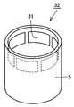
可動部材は、たとえば有底円筒状の形状を有し、先端にマグネットを有する。このマグネットは、インナーヨークとアウターヨーク間に配置される。図2と図3に可動部材の一例を示す。
【0035】
図2と図3に示すように、可動部材32は、可動部材本体を形成する樹脂スリーブ5と、該樹脂スリーブ5に装着された複数のマグネット31とを備える。マグネット31は、樹脂スリーブ5の周方向に、たとえば数mm程度の間隔をあけて配置される。樹脂スリーブ5の材料としては、たとえば耐熱性に優れたポリカーボネートあるいはこれにガラス繊維を混入したものを使用可能である。
【0036】
図3に示すように、マグネット31は、樹脂スリーブ5の内周部7に取り付けられる。該マグネット31は、接着剤などを用いて樹脂スリーブ5に取付けてもよく、インサート成形により樹脂スリーブ5の成形と同時に樹脂スリーブ5に装着するようにしてもよい。図3の例では、樹脂スリーブ5の内周面に露出するようにマグネット31を樹脂スリーブ5の内周側に装着している。
【0037】
図3に示すように、樹脂スリーブ5の外周部6は、マグネット31の外周面を覆う。リニアモータ装置の作動時には特に、マグネット31に外側に広がろうとする力が作用する。この場合に、樹脂スリーブ5の外周部6がマグネット31の外周面を覆うことにより、上記の力によってマグネット31の位置ずれや脱落が生ずるのを抑制することができる。それにより、リニアモータ装置の動作効率の低下を抑制することができ、結果的にリニアモータ装置の動作効率を向上することが可能となる。
【0038】
また、マグネット31が装着された部分における可動部材32の厚みである樹脂スリーブ5の外周部6の厚みtは、たとえば、0.2mm以上1.0mm未満程度である。好ましくは、0.2mm以上0.5mm以下程度であり、より好ましくは、0.2mm以上0.3mm以下程度である。このようにマグネット装着部における可動部材32の厚みを薄くすることにより、可動部材32におけるマグネット装着部の磁気抵抗を低減することができ、リニアモータ装置の動作効率を向上することが可能となる。
【0039】
第1と第2クランプリングの材料としては、たとえばポリカーボネートやポリブチレンテレフタレートなどの樹脂、あるいはこれらにガラス繊維を混入したものを使用可能である。なお、スターリング機関に使用する場合には、第1と第2クランプリングの材料として耐熱性に優れ吸湿量の少ない材料を使用することが好ましい。
【0040】
次に、本実施の形態におけるリニアモータ装置1の製造方法について、図4〜図6を用いて説明する。
【0041】
まず、上記のアウターヨークブロックと第1と第2クランプリングとをそれぞれ作製する。アウターヨークブロックは、電磁鋼鈑の積層材を加工して作製することができ、第1と第2クランプリングは、たとえば射出成形を用いて樹脂により成形可能である。また、コイルをボビンに巻き付けたコイル巻付体も別途作製しておく。
【0042】
これと並行して、可動部材も別途作製しておく。可動部材を作製するには、まず相対的に外径が大きくて肉厚の厚い第1部分と、相対的に外径が小さくて肉厚の薄い第2部分とを有するように樹脂製のスリーブを成形すると同時に第1部分の内周面にマグネットを装着する。このようにスリーブの成形とマグネットの装着とを同時に行うことにより、工程を簡略化することができる。
【0043】
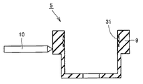
図4および図5に示す例では、図示しない金型内に予めマグネット31を設置した状態で樹脂を金型内に射出することにより、マグネット31を設置した部分に突出部(第1部分)9を有する樹脂スリーブ5を成型する。 なお、図4および図5に示す形状の樹脂スリーブ5を成形した後に、該樹脂スリーブ5に接着剤などを用いてマグネット31を装着するようにしてもよい。この場合には、比較的厚い部分にマグネット31を装着することとなるので、容易かつ確実にマグネット31を樹脂スリーブ5に装着することができる。
【0044】
次に、マグネット装着部における樹脂スリーブ5の厚みを減じる。たとえば、図6に示すように、切削工具10を用いて、樹脂スリーブ5の厚みの大きい部分である突出部9の外周面に切削加工を施し、突出部9の外周面から樹脂スリーブ5の厚みを減じる。
【0045】
上記のようにマグネット装着後にマグネット装着部における樹脂スリーブ5の厚みを減じることにより、図3に示すように、樹脂スリーブ5の外周部6の厚みtを、たとえば0.2mm〜0.3mm程度にまで薄くすることができる。このようにして可動部材32を作製することができる。
【0046】
他方、アウターヨークブロックの凸部を第1と第2クランプリングの凹部にそれぞれ嵌め込んだ状態で、アウターヨークブロックと、第1および第2クランプリングとを結合する。
【0047】
次に、アウターヨークブロック間にコイル巻付体を挟み込んだ状態で、第1と第2クランプリング間を連結する。その後、アウターヨークブロック間を接続する。たとえば、溶接によりアウターヨークブロックを選択的に溶着すればよい。
【0048】
次に、上記の第1と第2クランプリングで挟持された構造体の内側にインナーヨークと可動部材31とを設置する。可動部材32を設置する際には、インナーヨークとアウターヨークとの間に上記のマグネット31が位置するように可動部材32を配設する。
【0049】
以上の工程を経て本実施の形態におけるリニアモータ装置1を製造することができる。
【0050】
次に、上記のリニアモータ装置を備えた本発明の1つの実施の形態におけるスターリング機関について、図1を用いて説明する。なお、以下の説明では、本発明をスターリング機関の一例であるスターリング冷凍機に適用した場合について説明するが、スターリング冷凍機以外のスターリング機関にも本発明は適用可能である。
【0051】
図1に、本実施の形態におけるスターリング冷凍機20の概略構成を示す。図1に示すように、スターリング冷凍機20は、ケーシング21と、該ケーシング21に設置されたシリンダ22と、シリンダ22内で往復動するピストン23およびディスプレーサ24と、再生器25と、圧縮空間(第1作動空間)26と、膨張空間(第2作動空間)27と、放熱部(ウォームヘッド)28と、吸熱部(コールドヘッド)29と、ピストン駆動手段としての前述のリニアモータ装置1と、ピストン23を支持し所定の弾性力を付与する、板バネなどのピストンスプリング(第1スプリング)33と、ディスプレーサ24を支持し所定の弾性力を付与する、板バネなどのディスプレーサスプリング(第2スプリング)34と、ディスプレーサロッド35と、背圧空間36とを備える。
【0052】
リニアモータ装置1は、シリンダ22の周囲に設置され、インナーヨーク30と、該インナーヨーク30の外側に配置されるアウターヨーク4と、インナーヨーク30とアウターヨーク4との間に配置されたコイル巻付体8および可動部材32と、アウターヨーク4を挟持する第1と第2クランプリング2,3と、ピストンスプリング33やディスプレーサスプリング34を支持する支持部16とを有する。
【0053】
可動部材32の基本的な構造は、前述の場合と同様である。可動部材32は、有底円筒状の形状を有し、可動部材32の筒状部がインナーヨーク30を取り囲むように設置される。可動部材32の一端は、接続部材を介してピストン23と接続される。また、可動部材32の筒状部におけるマグネット装着部は、インナーヨーク30とアウターヨーク4との間に配置され、それによりマグネット31はインナーヨーク30とアウターヨーク4との間に配置される。
【0054】
可動部材32の基本的な構造は前述の場合と同様であるので、可動部材32におけるマグネット装着部の厚みをたとえば0.2mm〜0.3mm程度にまで薄くすることができ、可動部材32におけるマグネット装着部の磁気抵抗を低減することができる。したがって、動作効率の優れたリニアモータ装置を備えたスターリング機関が得られる。
【0055】
また、マグネット31の外側面を覆う外周部を可動部材32に設けることで、該可動部材32におけるマグネット装着位置からのマグネット31の位置ずれあるいはマグネット31の脱落を抑制することができる。このことも、動作効率の優れたリニアモータ装置を備えたスターリング機関の作製に効果的に寄与し得る。
【0056】
ケーシング21は、スターリング冷凍機20の外殻(外壁)を構成する部分であり、シリンダ22をはじめとする種々の部品が該ケーシング21内に組付けられる。図1の例では、ケーシング21は、単一の容器で構成されず、背圧空間36を規定するとともにリニアモータ装置1を受け入れるベッセル部分と、放熱部28、再生器25および吸熱部29の外壁部分とで主に構成される。該ケーシング21の内部には、ヘリウムガスや水素ガス、窒素ガスなどの作動媒体が充填される。
【0057】
シリンダ22は、略円筒状の形状を有し、該シリンダ22内において、ピストン23とディスプレーサ24とは同軸上に間隔をあけて配置され、このピストン23およびディスプレーサ24によってシリンダ22内の作動空間が圧縮空間26と膨張空間27とに区画される。圧縮空間26は主に放熱部28によって囲まれ、膨張空間27は主に吸熱部29によって囲まれている。
【0058】
圧縮空間26と膨張空間27との間には再生器25が配設されており、この再生器25を介してこれら両空間が連通する。それにより、スターリング冷凍機20内に閉回路が構成される。この閉回路内に封入された作動媒体が、ピストン23およびディスプレーサ24の動作に合わせて流動することにより、逆スターリングサイクルが実現する。
【0059】
ピストン23の一端はピストンスプリング33と接続される。該ピストンスプリング33とリニアモータ装置1により、シリンダ22内でピストン23を所望の振幅で周期的に往復動させることが可能となる。
【0060】
次に、本実施の形態におけるスターリング冷凍機20の動作について説明する。
【0061】
まず、リニアモータ装置1を作動させてピストン23を駆動する。より詳しくは、コイル巻付体8のコイルに通電し、可動部材32のマグネット31との間に推力が発生させる。この推力により可動部材32がシリンダ22の軸方向に沿って移動する。このとき可動部材32はピストン23と接続されているので、可動部材32とともにピストン23も、シリンダ22の軸方向に移動する。このようにしてリニアモータ装置1によって駆動されたピストン23は、ディスプレーサ24に接近し、圧縮空間26内の作動媒体(作動ガス)を圧縮する。
【0062】
ピストン23がディスプレーサ24に接近することにより、圧縮空間26内の作動媒体の温度は上昇するが、放熱部28によってこの圧縮空間26内に発生した熱が外部へと放出される。そのため、圧縮空間26内の作動媒体の温度はほぼ等温に維持される。すなわち、本過程は、逆スターリングサイクルにおける等温圧縮過程に相当する。
【0063】
ピストン23がディスプレーサ24に接近した後にディスプレーサ24は吸熱部29側に移動する。ピストン23によって圧縮空間26内において圧縮された作動媒体は再生器25内に流入し、さらに膨張空間27へと流れ込む。その際、作動媒体の持つ熱が再生器25に蓄熱される。すなわち、本過程は、逆スターリングサイクルの等容冷却過程に相当する。
【0064】
膨張空間27内に流入した高圧の作動媒体は、ディスプレーサ24がピストン23側へ移動することにより膨張する。これにより、膨張空間27内の作動媒体の温度は下降するが、吸熱部29によって外部の熱が膨張空間27内へと伝熱されるため、膨張空間27内はほぼ等温に保たれる。すなわち、本過程は、逆スターリングサイクルの等温膨張過程に相当する。
【0065】
その後、ディスプレーサ24がピストン23から遠ざかる方向に移動し始める。それにより、膨張空間27内の作動媒体は再生器25を通過して再び圧縮空間26側へと戻る。その際、再生器25に蓄熱されていた熱が作動媒体に与えられるため、作動媒体は昇温する。すなわち、本過程は、逆スターリングサイクルの等容加熱過程に相当する。
【0066】
この一連の過程(等温圧縮過程−等容冷却過程−等温膨張過程−等容加熱過程)が繰り返されることにより、逆スターリングサイクルが構成される。この結果、吸熱部29は徐々に低温になり、極低温を有するに至る。
【0067】
次に、本発明の1つの実施の形態におけるリニア圧縮機について図7を用いて説明する。
【0068】
図7に示すように、リニア圧縮機40は、ケーシング41内に設置されたシリンダ42と、該シリンダ42内で往復動するピストン43と、シリンダ42の周囲に設置されピストン43を駆動する上述のリニアモータ装置1と、ピストン42を付勢するピストンスプリング(板バネ)46と、シリンダを支持する支持機構部とを備える。
【0069】
リニアモータ装置1は、シリンダ42の周囲に設置され、インナーヨーク30と、該インナーヨーク30の外側に配置されるアウターヨーク4と、インナーヨーク30とアウターヨーク4との間に配置されたコイル巻付体8および可動部材32と、アウターヨーク4を挟持する第1と第2クランプリング2,3と、ピストンスプリング46を支持する支持部16とを有する。
【0070】
インナーヨーク30は、シリンダ42の外周を取り囲むように設けられ、該インナーヨーク30を取り囲むように円筒状の可動部材32を配置する。可動部材32の基本的な構造は、前述の場合と同様である。可動部材32は、ピストン43と接続され、先端にマグネット31を有する。該マグネット31をインナーヨーク30とアウターヨーク4との間に配置する。
【0071】
可動部材32の基本的な構造は、前述の場合と同様であるので、可動部材32におけるマグネット装着部の厚みを0.2mm〜0.3mm程度にまで薄くすることができ、可動部材32におけるマグネット装着部の磁気抵抗を低減することができる。したがって、動作効率の優れたリニアモータ装置を備えたリニア圧縮機が得られる。
【0072】
また、マグネット31の外側面を覆う外周部を可動部材32に設けることで、該可動部材32におけるマグネット装着位置からのマグネット31の位置ずれあるいはマグネット31の脱落を抑制することができる。このことも、動作効率の優れたリニアモータ装置を備えたリニア圧縮機の作製に効果的に寄与し得る。
【0073】
第1クランプリング2は、ピストンスプリング46を支持する支持部16を有する。該支持部16に取付けられた支持部材を介してピストンスプリング33が支持部16と接続される。
【0074】
シリンダ42は、ケーシング41内で支持機構部により支持されるが、該支持機構部は、図7の例では、ケーシング41の内部に固定される支持板49と、該支持板49上に搭載されシリンダ42を支持するコイルスプリング48とで構成される。
【0075】
また、シリンダ42の一端側にプレート47を介してヘッドカバー45を固定する。該ヘッドカバー45とピストン43の頭部との間に冷媒が圧縮される圧縮空間44が形成される。
【0076】
次に、上記の構造のリニア圧縮機の動作について説明する。まず、コイル巻付体8のコイルに通電すると、可動部材32のマグネット31との間に推力が発生し、この推力により可動部材32がシリンダ42の軸方向に沿って移動する。このとき可動部材32はピストン43と接続されているので、可動部材32とともにピストン43も、シリンダ42の軸方向に移動する。
【0077】
冷媒は、図示しない吸入管からケーシング41内に導入され、ヘッドカバー45およびプレート47内の通路を通過して圧縮空間44内に入る。この圧縮空間44内で、冷媒はピストン43により圧縮され、その後、図示しない吐出管を通って外部に吐出される。
【0078】
以上のように本発明の実施の形態について説明を行なったが、今回開示された実施の形態はすべての点で例示であって制限的なものではないと考えられるべきである。本発明の範囲は特許請求の範囲によって示され、特許請求の範囲と均等の意味および範囲内でのすべての変更が含まれることが意図される。
【0079】
【発明の効果】
本発明によれば、リニアモータ装置の可動部材におけるマグネット装着部の磁気抵抗を低減することができるので、リニアモータ装置の動作効率を向上することができる。また、可動部材におけるマグネット装着位置からのマグネットの位置ずれあるいはマグネットの脱落を抑制することができるので、このこともリニアモータ装置の動作効率向上に寄与し得る。
【0080】
本発明のスターリング機関およびリニア圧縮機は、上記のような動作効率の優れたリニアモータ装置を備えるので、高性能なスターリング機関およびリニア圧縮機となり得る。
【図面の簡単な説明】
【図1】本発明の1つの実施の形態におけるスターリング冷凍機を示す断面図である。
【図2】本発明の1つの実施の形態におけるリニアモータ装置の可動部材を示す斜視図である。
【図3】図2に示す可動部材の断面図である。
【図4】本発明の1つの実施の形態におけるリニアモータ装置の製造工程の特徴的な第1工程を示す斜視図である。
【図5】図4に示す状態の可動部材の断面図である。
【図6】本発明の1つの実施の形態におけるリニアモータ装置の製造工程の特徴的な第2工程を示す断面図である。
【図7】本発明の1つの実施の形態におけるリニア圧縮機の断面図である。
【符号の説明】
1 リニアモータ装置、2 第1クランプリング、3 第2クランプリング、4 アウターヨーク、5 樹脂スリ−ブ、6 外周部、7 内周部、8 コイル巻付体、9 突出部、10 切削工具、16 支持部、20 スターリング冷凍機、21,41 ケーシング、22,42 シリンダ、23,43 ピストン、24 ディスプレーサ、25 再生器、26,44 圧縮空間、27 膨張空間、28 放熱部、29 吸熱部、30 インナーヨーク、31 マグネット、32 可動部材、33,46 ピストンスプリング、34 ディスプレーサスプリング、35 ディスプレーサロッド、36 背圧空間、40 リニア圧縮機、45 ヘッドカバー、47 プレート、48 コイルスプリング、49 支持板。[0001]
BACKGROUND OF THE INVENTION
The present invention relates to a linear motor device, a manufacturing method thereof, a linear compressor having the linear motor device, and a Stirling engine.
[0002]
[Prior art]
Conventionally, in a Stirling engine or a linear compressor, a linear motor device is used as a driving means for driving a piston. An example of a piston operating part in the linear motor device is disclosed in, for example, Japanese Patent Application Laid-Open No. 2002-155859.
[0003]
In the above document, a piston fastening boss to which a piston is fastened, a plurality of magnets arranged at equal intervals on a concentric line with the piston fastening boss, and a piston fastening boss and a plurality of magnets are connected and integrated. And a piston operating part including a connecting member made of resin. The piston operating part is molded by injecting resin in a state where a piston fastening boss and a plurality of magnets are mounted on an injection molding machine.
[0004]
[Patent Document 1]
Japanese Patent Laid-Open No. 2002-155859
[Problems to be solved by the invention]
In the piston operating part described in the above document, the magnet is exposed on the outer periphery of the piston operating part. During the operation of the linear motor device, a force that spreads outward acts on the magnet, and this force may cause the magnet to shift or drop from the mounting position in the piston operating portion. In this case, a loss occurs in the magnetic circuit, and as a result, the operation efficiency of the linear motor device can be reduced.
[0006]
In addition, although the magnet is mounted on the resin portion of the piston operating portion, the thinner the resin portion (magnet mounting portion) where the magnet is mounted, the more the magnetic resistance can be reduced. The operating efficiency is improved.
[0007]
However, since the piston operating part described in the above document is manufactured by insert molding, it is difficult to reduce the thickness of the magnet holding part in the piston operating part to about 1.0 mm. For this reason, it is difficult to effectively reduce the magnetic resistance in the vicinity of the magnet mounting portion, which also contributes to a decrease in the operating efficiency of the linear motor device.
[0008]
The present invention has been made to solve the above problems, and provides a linear motor device and a method for manufacturing the same, a linear compressor having the linear motor device, and a Stirling engine that can improve the operation efficiency. The purpose is to do.
[0009]
[Means for Solving the Problems]
In one aspect, the linear motor device according to the present invention includes an inner yoke, an outer yoke disposed outside the inner yoke, and a portion where the magnet is mounted between the inner yoke and the outer yoke. The movable member has a thickness of 0.2 mm or more and less than 1.0 mm at a portion where the magnet is mounted. Here, “the thickness of the movable member” means the thickness of the movable member main body excluding the thickness of the magnet.
[0010]
By reducing the thickness of the movable member to 0.2 mm or more and less than 1.0 mm as described above, the magnetic resistance of the magnet mounting portion in the movable member can be reduced.
[0011]
In another aspect, the linear motor device according to the present invention includes the inner yoke, the outer yoke, and the movable member described above, and the movable member is provided with an outer peripheral portion that covers the outer surface of the magnet.
[0012]
In this way, by providing the movable member with the outer peripheral portion covering the outer surface of the magnet, even when a force to spread outward acts between the magnets, the displacement of the magnet from the magnet mounting position on the movable member or the magnet Dropout can be effectively suppressed.
[0013]
In still another aspect, a linear motor device according to the present invention includes the above-described inner yoke and outer yoke, and a movable resin sleeve having a magnet-mounted portion located between the inner yoke and the outer yoke. . Then, the magnet is mounted on the inner peripheral side of the movable resin sleeve so that the outer peripheral portion of the movable resin sleeve covers the outer surface of the magnet, and the thickness of the outer peripheral portion of the movable resin sleeve in the portion where the magnet is mounted is 0.2 mm or more. It shall be less than 1.0 mm.
[0014]
In the case of this aspect, since the thickness of the movable member main body in the mounting portion of the magnet is thin, the magnetic resistance is reduced, and the displacement or dropping of the magnet from the mounting position on the movable member can also be suppressed.
[0015]
In one aspect, the method for manufacturing a linear motor device according to the present invention includes the following steps. A resin sleeve is formed so as to have a first portion having a relatively large outer diameter and a second portion having a relatively small outer diameter. A magnet is attached to the inner peripheral surface of the first portion of the sleeve. After mounting the magnet, the movable member is produced by reducing the thickness of the first portion from the outer peripheral surface of the first portion. The movable member is disposed so that the magnet is positioned between the inner yoke and the outer yoke.
[0016]
Thus, by forming a thick (thick) portion of the outer diameter in advance in the resin sleeve and attaching the magnet to the thick portion, the magnet can be attached easily and reliably. Moreover, the thickness of the movable member main body in the magnet mounting portion can be reduced by reducing the thickness of the first portion after the magnet is mounted.
[0017]
In another aspect, the method for manufacturing a linear motor device according to the present invention includes the following steps. A resin sleeve is formed so as to have a relatively thick (thick) first portion and a relatively thin second portion, and at the same time, a magnet is attached to the inner peripheral surface of the first portion. The movable member is manufactured by reducing the thickness of the first portion from the outer peripheral surface side of the first portion. The movable member is disposed so that the magnet is positioned between the inner yoke and the outer yoke.
[0018]
Also in this aspect, since the thickness of the first portion is reduced after the magnet is mounted, the thickness of the movable member main body in the magnet mounting portion can be reduced. In addition, since the forming of the sleeve and the mounting of the magnet are performed at the same time, the process can be simplified.
[0019]
The forming step of the sleeve preferably includes a step of forming the sleeve so that the outer peripheral surface of the first portion protrudes outward from the outer peripheral surface of the second portion. Further, the step of reducing the thickness of the first portion preferably includes a step of reducing the thickness of the first portion by cutting the outer peripheral surface of the first portion.
[0020]
As described above, the sleeve is formed in advance so that the outer peripheral surface of the first portion protrudes outward from the outer peripheral surface of the second portion, and the outer peripheral surface of the first portion is cut with the magnet attached. Thereby, the thickness of the movable member in a magnet mounting part can be made thin easily.
[0021]
In one aspect, a linear compressor according to the present invention includes a cylinder installed in a casing, a piston that reciprocates in the cylinder, and a linear motor device that is installed around the cylinder and drives the piston. The linear motor device includes an inner yoke, an outer yoke disposed on the outer side of the inner yoke, and a movable member having a magnet-mounted portion between the inner yoke and the outer yoke, The thickness of the movable member in the portion where the magnet is mounted is 0.2 mm or more and less than 1.0 mm.
[0022]
Thus, by reducing the thickness of the magnet mounting portion in the movable member of the linear motor device, the magnetic resistance of the magnet mounting portion in the movable member can be reduced. Therefore, a linear compressor provided with a linear motor device with excellent operating efficiency can be obtained.
[0023]
In another aspect of the linear compressor according to the present invention, the linear motor device is located between an inner yoke, an outer yoke disposed outside the inner yoke, and the inner yoke and the outer yoke. A movable member having a portion on which a magnet is mounted, and the movable member has an outer peripheral portion that covers an outer surface of the magnet.
[0024]
In this way, by providing the movable member with the outer peripheral portion that covers the outer surface of the magnet in the linear motor device, even when a force in the direction toward the outer peripheral side of the movable member acts on the magnet, the magnet mounting position on the movable member can be reduced. It is possible to effectively suppress the displacement of the magnet or the falling of the magnet. Therefore, a linear compressor provided with a linear motor device with excellent operating efficiency can be obtained.
[0025]
In one aspect, a Stirling engine according to the present invention includes a cylinder installed in a casing, a piston and a displacer that reciprocates in the cylinder, and a linear motor that is installed around the cylinder and reciprocates in the cylinder. A device and a spring biasing the displacer. The linear motor device includes an inner yoke, an outer yoke disposed on the outer side of the inner yoke, and a movable member having a magnet-mounted portion between the inner yoke and the outer yoke, The thickness of the movable member in the portion where the magnet is mounted is 0.2 mm or more and less than 1.0 mm.
[0026]
Thus, by reducing the thickness of the magnet mounting portion in the movable member of the linear motor device, the magnetic resistance of the magnet mounting portion in the movable member can be reduced. Therefore, a Stirling engine provided with a linear motor device with excellent operating efficiency can be obtained.
[0027]
In another aspect of the Stirling engine according to the present invention, the linear motor device is located between the inner yoke, the outer yoke disposed outside the inner yoke, and the inner yoke and the outer yoke. And a movable member having a portion to which the magnet is mounted, and the movable member has an outer peripheral portion that covers the outer surface of the magnet.
[0028]
As described above, by providing the movable member with the outer peripheral portion covering the outer surface of the magnet in the linear motor device, it is possible to suppress the displacement of the magnet from the magnet mounting position or the falling of the magnet in the movable member. Also in this case, a Stirling engine provided with a linear motor device with excellent operating efficiency can be obtained.
[0029]
DETAILED DESCRIPTION OF THE INVENTION
Hereinafter, embodiments of the present invention will be described with reference to FIGS.
[0030]
A linear motor device according to an embodiment of the present invention includes an inner yoke, an outer yoke disposed outside the inner yoke, a coil wound body disposed between the inner yoke and the outer yoke, and an inner yoke A movable member having a portion on which a magnet (typically a permanent magnet) is mounted is provided between the yoke and the outer yoke, and annular first and second clamp rings that sandwich the outer yoke.
[0031]
The inner yoke is disposed, for example, on the outer periphery of a cylinder having a piston inside. The outer yoke is sandwiched between the first and second clamp rings, and is arranged at an interval in the circumferential direction of the first and second clamp rings. The outer yoke can be composed of, for example, a plurality of outer yoke blocks arranged so as to be aligned in the axial direction of the linear motor device. The outer yoke blocks are coupled (fixed) to each other and are held by the first and second clamp rings. The outer yoke block can be produced, for example, by laminating a plurality of electromagnetic steel plates.
[0032]
The outer yoke block has, for example, a substantially U shape, and has a convex portion. In this case, the first and second clamp rings are provided with a concave portion for receiving the convex portion of the outer yoke block, and the convex portion of the outer yoke block is fitted into the concave portion of the first and second clamp rings and joined. Thereby, the outer yoke block can be held by the first and second clamp rings.
[0033]
The coil wound body includes a bobbin and a coil wound around the bobbin. A coil winding body is hold | maintained at an outer yoke, for example by being clamped by the outer yoke block. However, the coil wound body may be held by the first and second clamp rings.
[0034]
The movable member has, for example, a bottomed cylindrical shape and has a magnet at the tip. The magnet is disposed between the inner yoke and the outer yoke. 2 and 3 show an example of the movable member.
[0035]
As shown in FIGS. 2 and 3, the
[0036]
As shown in FIG. 3, the
[0037]
As shown in FIG. 3, the outer
[0038]
Further, the thickness t of the outer
[0039]
As materials for the first and second clamp rings, for example, resins such as polycarbonate and polybutylene terephthalate, or those in which glass fibers are mixed can be used. In addition, when using for a Stirling engine, it is preferable to use the material which is excellent in heat resistance and has little moisture absorption as a material of a 1st and 2nd clamp ring.
[0040]
Next, a method for manufacturing the
[0041]
First, the outer yoke block and the first and second clamp rings are produced. The outer yoke block can be manufactured by processing a laminated material of electromagnetic steel plates, and the first and second clamp rings can be formed of resin using, for example, injection molding. In addition, a coil wound body in which the coil is wound around the bobbin is prepared separately.
[0042]
In parallel with this, a movable member is also prepared separately. In order to manufacture the movable member, first, a resin-made sleeve is provided so as to have a first portion having a relatively large outer diameter and a large thickness and a second portion having a relatively small outer diameter and a small thickness. At the same time as molding, a magnet is mounted on the inner peripheral surface of the first portion. Thus, the process can be simplified by simultaneously forming the sleeve and attaching the magnet.
[0043]
In the example shown in FIGS. 4 and 5, the
[0044]
Next, the thickness of the
[0045]
By reducing the thickness of the
[0046]
On the other hand, the outer yoke block and the first and second clamp rings are coupled with the convex portions of the outer yoke block fitted into the concave portions of the first and second clamp rings, respectively.
[0047]
Next, the first and second clamp rings are connected with the coil winding body sandwiched between the outer yoke blocks. Thereafter, the outer yoke blocks are connected. For example, the outer yoke block may be selectively welded by welding.
[0048]
Next, the inner yoke and the
[0049]
The
[0050]
Next, a Stirling engine according to one embodiment of the present invention provided with the above linear motor device will be described with reference to FIG. In the following description, the case where the present invention is applied to a Stirling refrigerator that is an example of a Stirling engine will be described, but the present invention can also be applied to a Stirling engine other than a Stirling refrigerator.
[0051]
In FIG. 1, schematic structure of the
[0052]
The
[0053]
The basic structure of the
[0054]
Since the basic structure of the
[0055]
Further, by providing the
[0056]
The
[0057]
The
[0058]
A
[0059]
One end of the
[0060]
Next, operation | movement of the
[0061]
First, the
[0062]
When the
[0063]
After the
[0064]
The high-pressure working medium that has flowed into the
[0065]
Thereafter, the
[0066]
By repeating this series of processes (isothermal compression process-isovolume cooling process-isothermal expansion process-isovolume heating process), an inverse Stirling cycle is configured. As a result, the
[0067]
Next, a linear compressor in one embodiment of the present invention will be described with reference to FIG.
[0068]
As shown in FIG. 7, the
[0069]
The
[0070]
The
[0071]
Since the basic structure of the
[0072]
Further, by providing the
[0073]
The
[0074]
The cylinder 42 is supported by a support mechanism unit in the
[0075]
Further, the
[0076]
Next, the operation of the linear compressor having the above structure will be described. First, when the coil of the coil wound
[0077]
The refrigerant is introduced into the
[0078]
Although the embodiment of the present invention has been described above, it should be considered that the embodiment disclosed this time is illustrative and not restrictive in all respects. The scope of the present invention is defined by the terms of the claims, and is intended to include any modifications within the scope and meaning equivalent to the terms of the claims.
[0079]
【The invention's effect】
According to the present invention, since the magnetic resistance of the magnet mounting portion in the movable member of the linear motor device can be reduced, the operation efficiency of the linear motor device can be improved. Further, since the displacement of the magnet from the magnet mounting position on the movable member or the falling off of the magnet can be suppressed, this can also contribute to the improvement of the operation efficiency of the linear motor device.
[0080]
Since the Stirling engine and the linear compressor of the present invention include the linear motor device having excellent operation efficiency as described above, it can be a high-performance Stirling engine and linear compressor.
[Brief description of the drawings]
FIG. 1 is a cross-sectional view showing a Stirling refrigerator in one embodiment of the present invention.
FIG. 2 is a perspective view showing a movable member of the linear motor device according to one embodiment of the present invention.
3 is a cross-sectional view of the movable member shown in FIG.
FIG. 4 is a perspective view showing a characteristic first step of a manufacturing process of the linear motor device according to one embodiment of the present invention.
5 is a cross-sectional view of the movable member in the state shown in FIG.
FIG. 6 is a cross-sectional view showing a characteristic second step of the manufacturing process of the linear motor device according to one embodiment of the present invention.
FIG. 7 is a cross-sectional view of a linear compressor in one embodiment of the present invention.
[Explanation of symbols]
DESCRIPTION OF
Claims (7)
前記インナーヨークの外側に配置されるアウターヨークと、
前記インナーヨークと前記アウターヨークとの間に位置してマグネットが装着された部分を有する可動部材とを備え、
前記マグネットが装着された部分における前記可動部材の厚みが0.2mm以上1.0mm未満である、リニアモータ装置。An inner yoke,
An outer yoke disposed outside the inner yoke;
A movable member having a magnet-mounted portion located between the inner yoke and the outer yoke;
The linear motor device, wherein a thickness of the movable member in a portion where the magnet is mounted is 0.2 mm or more and less than 1.0 mm.
前記インナーヨークの外側に配置されるアウターヨークと、
前記インナーヨークと前記アウターヨークとの間に位置してマグネットが装着された部分を有する可動部材とを備え、
前記可動部材は、前記マグネットの外側面を覆う外周部を有する、リニアモータ装置。An inner yoke,
An outer yoke disposed outside the inner yoke;
A movable member having a magnet-mounted portion located between the inner yoke and the outer yoke;
The said movable member is a linear motor apparatus which has an outer peripheral part which covers the outer surface of the said magnet.
前記インナーヨークの外側に配置されるアウターヨークと、
前記インナーヨークと前記アウターヨークとの間に位置してマグネットが装着された部分を有する可動樹脂スリーブとを備え、
前記可動樹脂スリーブの外周部が前記マグネットの外側面を覆うように前記可動樹脂スリーブの内周側に前記マグネットを装着し、
前記マグネットが装着された部分における前記可動樹脂スリーブの外周部の厚みが0.2mm以上1.0mm未満である、リニアモータ装置。An inner yoke,
An outer yoke disposed outside the inner yoke;
A movable resin sleeve having a magnet-mounted portion located between the inner yoke and the outer yoke;
The magnet is mounted on the inner peripheral side of the movable resin sleeve so that the outer peripheral portion of the movable resin sleeve covers the outer surface of the magnet,
The linear motor device, wherein a thickness of an outer peripheral portion of the movable resin sleeve in a portion where the magnet is mounted is 0.2 mm or more and less than 1.0 mm.
前記スリーブの第1部分の内周面にマグネットを装着する工程と、
前記マグネットの装着後に、前記第1部分の外周面から前記第1部分の厚みを減じることにより可動部材を作製する工程と、
インナーヨークとアウターヨークとの間に前記マグネットが位置するように前記可動部材を配設する工程と、
を備えた、リニアモータ装置の製造方法。Molding a resin sleeve so as to have a first portion having a relatively large outer diameter and a second portion having a relatively small outer diameter;
Attaching a magnet to the inner peripheral surface of the first portion of the sleeve;
After mounting the magnet, producing a movable member by reducing the thickness of the first part from the outer peripheral surface of the first part;
Disposing the movable member such that the magnet is positioned between the inner yoke and the outer yoke;
A method for manufacturing a linear motor device.
前記第1部分の外周面側から前記第1部分の厚みを減じることにより可動部材を作製する工程と、
インナーヨークとアウターヨークとの間に前記マグネットが位置するように前記可動部材を配設する工程と、
を備えた、リニアモータ装置の製造方法。Forming a resin sleeve so as to have a first portion having a relatively large outer diameter and a second portion having a relatively small outer diameter, and simultaneously mounting a magnet on the inner peripheral side of the first portion; ,
Producing a movable member by reducing the thickness of the first portion from the outer peripheral surface side of the first portion;
Disposing the movable member such that the magnet is positioned between the inner yoke and the outer yoke;
A method for manufacturing a linear motor device.
前記シリンダ内で往復動するピストンと、
前記シリンダの周囲に設置され、前記ピストンを往復動させる請求項1〜3のいずれかに記載のリニアモータ装置とを備えるリニア圧縮機。A cylinder installed in the casing;
A piston that reciprocates within the cylinder;
The linear compressor provided with the linear motor apparatus in any one of Claims 1-3 installed in the circumference | surroundings of the said cylinder, and reciprocatingly moving the said piston.
前記シリンダ内で往復動するピストンおよびディスプレーサと、
前記シリンダの周囲に設置され、前記ピストンを前記シリンダ内で往復動させる請求項1〜3のいずれかに記載のリニアモータ装置と、
前記ディスプレーサを付勢するスプリングとを備えるスターリング機関。A cylinder installed in the casing;
A piston and a displacer reciprocating in the cylinder;
The linear motor device according to any one of claims 1 to 3, wherein the linear motor device is installed around the cylinder and reciprocates the piston in the cylinder.
A Stirling engine comprising a spring for biasing the displacer.
Priority Applications (1)
| Application Number | Priority Date | Filing Date | Title |
|---|---|---|---|
| JP2003178326A JP2005020808A (en) | 2003-06-23 | 2003-06-23 | Linear motor device and its manufacturing method, linear compressor, and stirling engine |
Applications Claiming Priority (1)
| Application Number | Priority Date | Filing Date | Title |
|---|---|---|---|
| JP2003178326A JP2005020808A (en) | 2003-06-23 | 2003-06-23 | Linear motor device and its manufacturing method, linear compressor, and stirling engine |
Publications (2)
| Publication Number | Publication Date |
|---|---|
| JP2005020808A true JP2005020808A (en) | 2005-01-20 |
| JP2005020808A5 JP2005020808A5 (en) | 2005-10-27 |
Family
ID=34179990
Family Applications (1)
| Application Number | Title | Priority Date | Filing Date |
|---|---|---|---|
| JP2003178326A Pending JP2005020808A (en) | 2003-06-23 | 2003-06-23 | Linear motor device and its manufacturing method, linear compressor, and stirling engine |
Country Status (1)
| Country | Link |
|---|---|
| JP (1) | JP2005020808A (en) |
Cited By (3)
| Publication number | Priority date | Publication date | Assignee | Title |
|---|---|---|---|---|
| WO2006112150A1 (en) * | 2005-03-30 | 2006-10-26 | Sharp Kabushiki Kaisha | Linear drive device |
| JP2014521300A (en) * | 2011-07-20 | 2014-08-25 | ワールプール・エシ・ア | Compressor with linear engine |
| CN112815565A (en) * | 2021-01-28 | 2021-05-18 | 宁波芯斯特林低温设备有限公司 | Stirling refrigerator |
-
2003
- 2003-06-23 JP JP2003178326A patent/JP2005020808A/en active Pending
Cited By (5)
| Publication number | Priority date | Publication date | Assignee | Title |
|---|---|---|---|---|
| WO2006112150A1 (en) * | 2005-03-30 | 2006-10-26 | Sharp Kabushiki Kaisha | Linear drive device |
| KR100887036B1 (en) | 2005-03-30 | 2009-03-04 | 샤프 가부시키가이샤 | Linear drive device |
| US7649285B2 (en) | 2005-03-30 | 2010-01-19 | Sharp Kabushiki Kaisha | Linear drive device |
| JP2014521300A (en) * | 2011-07-20 | 2014-08-25 | ワールプール・エシ・ア | Compressor with linear engine |
| CN112815565A (en) * | 2021-01-28 | 2021-05-18 | 宁波芯斯特林低温设备有限公司 | Stirling refrigerator |
Similar Documents
| Publication | Publication Date | Title |
|---|---|---|
| JP3579416B1 (en) | Linear motor device and manufacturing method thereof, linear compressor and Stirling engine | |
| US7775041B2 (en) | Stirling engine | |
| US7168248B2 (en) | Stirling engine | |
| CN100460781C (en) | Stirling engine | |
| JP2007506024A (en) | Motor stator fixing device for reciprocating compressor and method for fixing the same | |
| JP4220517B2 (en) | Cooler piston assembly | |
| JP3820588B2 (en) | Ring-shaped permanent magnet fixing structure | |
| JP2005020808A (en) | Linear motor device and its manufacturing method, linear compressor, and stirling engine | |
| KR100758067B1 (en) | Electromagnetic actuator, and stirling engine | |
| JP2004297858A5 (en) | ||
| JP5098499B2 (en) | Linear compressor for regenerative refrigerator | |
| KR100512002B1 (en) | Stirling refrigerator's Linear motor mounting | |
| JP2001057767A (en) | Electromagnetic reciprocating driving mechanism | |
| JP2950308B2 (en) | Stirling refrigerator | |
| JP2005037118A (en) | Sterling engine | |
| JP2001289525A (en) | Vibration-type compressor | |
| JPH05332626A (en) | Linear motor compressor in stirling freezer | |
| JP3989874B2 (en) | Linear compressor and Stirling engine equipped with the same | |
| KR101054429B1 (en) | Linear Motor Mounting Structure of Sterling Refrigerator | |
| JP2000266421A (en) | Stirling cycle engine | |
| WO2006085431A1 (en) | Piston for stirling engine | |
| JP2950303B2 (en) | Vibration compressor | |
| JP2004092618A (en) | Compressor | |
| JP2004293829A (en) | Driving device for sterling cycle engine | |
| JP2005042594A (en) | Stirling cycle engine |
Legal Events
| Date | Code | Title | Description |
|---|---|---|---|
| A521 | Written amendment |
Free format text: JAPANESE INTERMEDIATE CODE: A523 Effective date: 20050728 |
|
| A621 | Written request for application examination |
Effective date: 20050728 Free format text: JAPANESE INTERMEDIATE CODE: A621 |
|
| A977 | Report on retrieval |
Free format text: JAPANESE INTERMEDIATE CODE: A971007 Effective date: 20070130 |
|
| A131 | Notification of reasons for refusal |
Effective date: 20070206 Free format text: JAPANESE INTERMEDIATE CODE: A131 |
|
| A02 | Decision of refusal |
Free format text: JAPANESE INTERMEDIATE CODE: A02 Effective date: 20070605 |