JP2005016752A - Powder/grain material drying device - Google Patents
Powder/grain material drying device Download PDFInfo
- Publication number
- JP2005016752A JP2005016752A JP2003178815A JP2003178815A JP2005016752A JP 2005016752 A JP2005016752 A JP 2005016752A JP 2003178815 A JP2003178815 A JP 2003178815A JP 2003178815 A JP2003178815 A JP 2003178815A JP 2005016752 A JP2005016752 A JP 2005016752A
- Authority
- JP
- Japan
- Prior art keywords
- drying
- granular material
- sawdust
- movable member
- powder
- Prior art date
- Legal status (The legal status is an assumption and is not a legal conclusion. Google has not performed a legal analysis and makes no representation as to the accuracy of the status listed.)
- Granted
Links
- 238000001035 drying Methods 0.000 title claims abstract description 112
- 239000000843 powder Substances 0.000 title claims abstract description 22
- 239000000463 material Substances 0.000 title abstract description 7
- 238000009423 ventilation Methods 0.000 claims abstract description 38
- 239000008187 granular material Substances 0.000 claims description 50
- 239000002245 particle Substances 0.000 claims description 7
- 230000001105 regulatory effect Effects 0.000 claims description 7
- 230000002708 enhancing effect Effects 0.000 claims description 3
- 239000013618 particulate matter Substances 0.000 claims 1
- 230000033228 biological regulation Effects 0.000 abstract description 7
- 230000010355 oscillation Effects 0.000 abstract description 2
- 230000002349 favourable effect Effects 0.000 abstract 1
- 239000007787 solid Substances 0.000 abstract 1
- 230000000694 effects Effects 0.000 description 5
- 230000014759 maintenance of location Effects 0.000 description 4
- 238000003756 stirring Methods 0.000 description 4
- 235000013339 cereals Nutrition 0.000 description 3
- 238000000034 method Methods 0.000 description 3
- 244000068988 Glycine max Species 0.000 description 2
- 235000010469 Glycine max Nutrition 0.000 description 2
- 240000007594 Oryza sativa Species 0.000 description 2
- 235000007164 Oryza sativa Nutrition 0.000 description 2
- 241000533293 Sesbania emerus Species 0.000 description 2
- 244000061456 Solanum tuberosum Species 0.000 description 2
- 235000002595 Solanum tuberosum Nutrition 0.000 description 2
- 239000002361 compost Substances 0.000 description 2
- 238000010586 diagram Methods 0.000 description 2
- 239000000446 fuel Substances 0.000 description 2
- 235000012015 potatoes Nutrition 0.000 description 2
- 239000002994 raw material Substances 0.000 description 2
- 235000009566 rice Nutrition 0.000 description 2
- XLYOFNOQVPJJNP-UHFFFAOYSA-N water Substances O XLYOFNOQVPJJNP-UHFFFAOYSA-N 0.000 description 2
- 239000002023 wood Substances 0.000 description 2
- 230000003631 expected effect Effects 0.000 description 1
- 238000000465 moulding Methods 0.000 description 1
- 239000008188 pellet Substances 0.000 description 1
- 230000003578 releasing effect Effects 0.000 description 1
- 239000011435 rock Substances 0.000 description 1
Images


Landscapes
- Drying Of Solid Materials (AREA)
Abstract
Description
【0001】
【発明の属する技術分野】
本発明は、おが屑などの被乾燥粉粒物を循環させながら通風乾燥する粉粒物乾燥装置に関するものである。
【0002】
【従来の技術】
木材の加工、製材等に伴って発生するおが屑は、燃料、堆肥の原料、茸類の栽培基など、広範囲の利用が可能であるが、おが屑を燃料として利用する場合にはペレット状に成形されることが多くその場合、成形に最適な水分値で均質な状態に乾燥していることが必要であり、また堆肥の原料としたり茸類の栽培基として利用する場合にも、それぞれの利用の仕方に最も適した水分値で均質な状態に乾燥していることが求められる。
【0003】
一般に、丸太材などの製材に伴って発生するおが屑は、それ自体かなりの水分を含んでおり、また、木材の加工や材木の切断に伴って発生するおが屑も、その収集や保管の状況によるが、水分を多く含んだ状態で提供されるので、多くの場合、収集されるおが屑は、それぞれの利用方法に適した所要の水分まで乾燥しなければならないものである。
【0004】
このため、従来からおが屑の乾燥手段が種々提案されている。それを機能別に概ね分類すれば、被乾燥おが屑の静止堆積層に熱風を浴びせて乾燥するもの(特開昭48−2436号公報参照)、被乾燥おが屑を回転ドラムで撹拌しながら加熱乾燥するもの(特開60−2868号公報参照)、被乾燥おが屑をサイクロンで旋回させながら熱風を浴びせるもの(実願昭55−167157号:実開昭57−89196号のマイクロフィルム参照)、被乾燥おが屑を乾燥ドラム内で撹拌体で撹拌しながら熱風で乾燥するもの(実願平2−41864号:実開平4−1394号のマイクロフィルムまたは特開平7−312975号公報参照)がある。
【0005】
【発明が解決しようとする課題】
おが屑、米糠、油粕、コーヒー豆滓、大豆粕、おから、籾などの穀物のような粉粒物は、水分を多く含むと団子状にかたまった態様を呈するので、それを堆積したままで熱風を浴びせても乾燥効率が甚だ低く、また表面だけは乾燥しても全体を均等に乾燥することができないものである。また、粉粒物を乾燥し易いように回転ドラムや撹拌体により撹拌しても、粉粒物のかたまりがやや小さくなるだけで散粒状にほぐれた態様とはならず、やはり効率よく均等に乾燥することができないのが実情である。
【0006】
そこで、本発明は、内部に通風乾燥部を設けた乾燥槽の上部から被乾燥粉粒物を投入し、かつ通風乾燥部を流下させて下部から排出する循環をさせながら通風乾燥する粉粒物乾燥装置において、乾燥槽内の通風乾燥部を構成する給風胴および排風胴またはそれらのいずれか一方の頂部に可動部材を被せ、さらには通風乾燥部の下方の粉粒物繰り出し部の規制体頂部にも同様の可動部材を被せて、これら可動部材を往復滑動、揺動または振動させるなどの単独またはそれらの複合変動のための駆動手段を備えることによって、前記可動部材の変動により給風胴と排風胴の頂部およびその付近、さらには粉粒物繰り出し部の頂部およびその付近に生じる被乾燥粉粒物の固まりをほぐし、その良好な流動性を維持することにより、被乾燥粉粒物を効率よく全体を均等に乾燥することができる粉粒物乾燥装置を提供することを目的とするものである。
【0007】
【課題を解決するための手段】
上記目的を達成するため、本発明は請求項1ないし7に係る粉粒物乾燥装置を提供する。なお、本発明において粉粒体とは、おが屑、米糠、油粕、コーヒー豆滓、大豆粕、おから、籾などの穀物、その他の粉状ないしは粒状を呈する物を指称する。
【0008】
請求項1に係る粉粒物乾燥装置は、被乾燥粉粒物を循環させながら通風乾燥する粉粒物乾燥装置であって、被乾燥粉粒物を収容し循環させながら通風乾燥をする乾燥槽と、この乾燥槽に被乾燥粉粒物を投入して循環させる粉粒物揚送機とを備えて構成され、乾燥槽の内部には、給風胴と排風胴とを対向させてそれらの間を被乾燥粉粒物の流下路と成した通風乾燥部を設けてあり、通風乾燥部を構成する給風胴および排風胴またはそれらのいずれか一方の頂部には可動部材を被せてあって、この可動部材を往復滑動、揺動または振動させるなどの単独またはそれらの複合変動のための駆動手段を備えており、前記可動部材の変動によって給風胴と排風胴の頂部およびその付近に生じる被乾燥粉粒物の固まりをほぐし、その良好な流動性を維持するように構成されていることを特徴とするものである。
【0009】
請求項2に係る粉粒物乾燥装置は、請求項1記載の粉粒物乾燥装置において、乾燥槽の内部には、通風乾燥部の下方に乾燥槽の被乾燥紛粒物を定量的に流下させるための粉粒物繰り出し部を設けてあり、この粉粒物繰り出し部の粉粒物繰り出し規制体の頂部にも、往復滑動、揺動または振動させる可動部材を被せてあることを特徴とするものである。
【0010】
請求項3に係る粉粒物乾燥装置は、請求項2記載の粉粒物乾燥装置において、通風乾燥部の可動部材と粉粒物繰り出し部の可動体は、互いに直交する方向に設けられていることを特徴とするものである。
【0011】
請求項4に係る粉粒物乾燥装置は、請求項2または3記載の粉粒物乾燥装置において、通風乾燥部を構成する給風胴および排風胴の頂部または粉粒物繰り出し部の粉粒物繰り出し規制体の頂部は山形状であって、可動部材もそれらの形状に沿った山形状であることを特徴とするものである。
【0012】
請求項5に係る粉粒物乾燥装置は、請求項1ないし4のいずれかに記載の粉粒物乾燥装置において、可動部材はその裏側に、給風胴、排風胴または粉粒物繰り出し規制体の頂部に一定間隔を保って滑動自在に支持するローラを備えていることを特徴とするものである。
【0013】
請求項6に係る粉粒物乾燥装置は、請求項1ないし5のいずれかに記載の粉粒物乾燥装置において、複数の可動部材は、それぞれ各別に往復滑動、揺動または振動させる個別の駆動手段を備えていることを特徴とするものである。
【0014】
請求項7に係る粉粒物乾燥装置は、請求項1ないし6のいずれかに記載の粉粒物乾燥装置において、可動部材は、その往復滑動、揺動または振動などの変動による粉粒物のほぐし作用を増強させるための棒状突起を備えていることを特徴とするものである。
【0015】
【発明の実施の形態】
図面は本発明の一実施の形態に係る粉粒物乾燥装置として、おが屑乾燥装置を例示している。このため、発明の実施の形態において粉粒物はその一例であるおが屑と称するものとする。図1はおが屑乾燥装置の縦断正面図、図2は一部を破断して示す側面図、図3は乾燥槽の下部構造を示す斜視図、図4は乾燥部における可動部材およびその駆動構造を示す正面図、図5は同上断面図である。図6は可動部材の複数の変動態様を示す概念図である。
【0016】
図1ないし図3に示すように、本発明に係るおが屑乾燥装置1は、乾燥槽2と粉粒物揚送機3とで構成されている。乾燥槽2は、その上部から順におが屑収容部4、通風乾燥部5、おが屑滞留部6を成しており、おが屑滞留部6の下端は、複数の繰り出しロール7によるおが屑繰り出し部8を成している。9はその山形の繰り出し規制体である。10はおが屑収集部であり、その下端部にはおが屑排出スクリューコンベア11が設けられている。また、おが屑収容部4の上部、すなわち乾燥槽2の天面には、おが屑を均等分散させるための均分スクリューコンベア12が設けられている。乾燥槽2の上記おが屑排出スクリューコンベア11の搬送終端とおが屑揚送機3の下端側とはおが屑搬送樋13により接続されており、おが屑揚送機3の上端側と均分スクリューコンベア12とはおが屑搬送樋14により接続されている。上記おが屑搬送樋13はおが屑の流下を円滑にするため急勾配と成っており、おが屑搬送樋14も同様である。おが屑揚送機3はバケットコンベアであり、15は上部プーリ、16は下部プーリ、17は搬送ベルト、18はバケットである。
【0017】
乾燥槽2の下部は、おが屑収容部4、通風乾燥部5、おが屑滞留部6およびおが屑収集部10によって左右に2分されていて、その一方が熱風室19、他方が排風室20と成っている。なお、熱風室19には熱風発生装置が内蔵または外付けで装備され、排風室20には吸引ファンを介して、またはそのまま外気に通じさせてあり(なお、これらについてはいずれも図示していない。)、熱風室19から通風乾燥部5に吸引風または圧送風の熱風が送風され、かつ排風室20に排出されるように構成されている。
【0018】
乾燥槽2の天面には、おが屑収容部3の上部空間から吸引排気する吸引排気ファン21が設けられている。おが屑搬送樋13には未乾燥のおが屑投入口22が設けられており、おが屑搬送樋14には乾燥済みのおが屑排出口23がそれぞれ設けられている。24、25はそれらの開閉シャッタである。おが屑揚送機3には、揚送中に飛散する被乾燥おが屑を採取してその水分を計測する水分計測手段26を備えている。本発明に係るおが屑乾燥装置1にあっては、この水分計測手段26により、循環乾燥中のおが屑の水分が所定値になったことを検出された時点で、乾燥を終了するように構成してある。
【0019】
乾燥槽2の通風乾燥部5は、頂部が山形で多孔状の給風胴27と同様の排風胴28を交互に配設して、それらの間におが屑流下路29を形成して成るものであり、給風胴27は熱風室19に、排風胴28は排風室20にそれぞれ連通させてあって、熱風室19から熱風が給風胴27、おが屑流下路29を横切って排風胴28に流入したうえ排風室20に排出されるように成っている。
【0020】
通風乾燥部5の排風胴28の山形の頂部には、その山形に沿った形状の可動部材30が被せてある。この可動部材30は、その裏側に、排風胴28の頂部に一定間隔を保って滑動自在に支持する頂部の支持ローラ31および側部の支持ローラ32を備えている。可動部材30はその先端が支持部33に滑動自在に支持されており、34はその部分のカバーである。可動部材30の基端にはアクチュエータ35に連結されていて、アクチュエータ35の通電駆動により可動部材30が往復滑動されるように構成されている。このアクチュエータ35による駆動手段は、往復滑動のほか、揺動または振動させるなどの単独またはそれらの複合変動のための機能を備えてもよく、可動部材30の変動によって給風胴27と排風胴28の頂部およびその付近ないしは給風洞27の付近に生じる被乾燥おが屑の固まりをほぐし、その良好な流動性を維持するものである。
【0021】
可動部材30は、その往復滑動、揺動または振動などの変動によるおが屑のほぐし作用を増強させるための棒状突起36を複数備えたものとしてもよい。また、複数の可動部材30には、それぞれ各別に往復滑動、揺動または振動させる個別の駆動手段を備えてそれらの変動態様を複雑にすれば、おが屑のほぐし効果を一段と向上させることができる。図6において(A)は可動部材30の往復滑動態様、(B)は横方向の往復動態様、(C)は上下動態様、(D)は捻り動態様を示している。
【0022】
本発明に係るおが屑乾燥装置1においては、通風乾燥部5の下方に設けたおが屑繰り出し部8のおが屑繰り出し規制体9の頂部にも可動部材30を設けてあり、その構成は排風胴28に設けた可動部材30と同等である。図示の実施の形態においては、通風乾燥部5の可動部材30とおが屑繰り出し部8側の可動部材30は、互いに直交する方向に設けられているので、通風乾燥部5およびおが屑繰り出し部8付近におけるおが屑のほぐし効果が大きく、その流動性がいっそう良好である。また、通風乾燥部5の排風胴28だけでなく給風胴27の頂部にも同様の可動体30を設けることにより、おが屑の流動性をさらに良好ならしめることができる。なお、可動部材30を排風胴28に設けず給風胴27だけに設けても所期の効果を期待できるものである。
【0023】
本発明に係るおが屑乾燥装置1によれば、乾燥槽2内の通風乾燥部5を構成する給風胴27および排風胴28またはそれらのいずれか一方の頂部に可動部材30を被せ、さらには通風乾燥部5の下方のおが屑繰り出し部8のおが屑繰り出し規制体9にも同様の可動部材30を被せて、これら可動部材30を往復滑動、揺動または振動させるなどの単独またはそれらの複合変動のための駆動手段を備えているので、可動部材30の変動により給風胴27と排風胴28の頂部およびその付近、さらにはおが屑繰り出し部のおが屑繰り出し規制体9の頂部およびその付近に生じるおが屑の固まりをほぐし、その良好な流動性を維持することができる。このため、水分を多く含んだ被乾燥おが屑であっても効率よく全体を均等に乾燥することができるものである。
【0024】
【発明の効果】
本発明によれば、内部に通風乾燥部を設けた乾燥槽の上部から被乾燥粉粒物を投入し、かつ通風乾燥部を流下させて下部から排出する循環をさせながら通風乾燥する粉粒物乾燥装置において、乾燥槽内の通風乾燥部を構成する給風胴および排風胴またはそれらのいずれか一方の頂部に可動部材を被せ、さらには通風乾燥部の下方の粉粒物繰り出し部の規制体頂部にも同様の可動部材を被せて、これら可動部材を往復滑動、揺動または振動させるなどの単独またはそれらの複合変動のための駆動手段を備えることによって、前記可動部材の変動により給風胴と排風胴の頂部およびその付近、さらには粉粒物繰り出し部の頂部およびその付近に生じる被乾燥粉粒物の固まりをほぐし、その良好な流動性を維持することにより、被乾燥粉粒物を効率よく全体を均等に乾燥することができる効果が得られるものである。
【図面の簡単な説明】
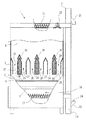
【図1】本発明の一実施の形態に係る粉粒物乾燥装置の一例であるおが屑乾燥装置を示す縦断正面図である。
【図2】同上一部を破断して示す側面図である。
【図3】同上乾燥槽の下部構造を示す斜視図である。
【図4】乾燥部における可動部材およびその駆動構造を示す正面図である。
【図5】同上断面図である。
【図6】可動部材の複数の変動態様を示す概念図である。
【符号の説明】
1 おが屑乾燥装置
2 乾燥槽
3 おが屑揚送機
4 おが屑収容部
5 通風乾燥部
6 おが屑滞留部
7 繰り出しロール
8 おが屑繰り出し部
9 おが屑繰り出し規制体
10 おが屑収集部
11 おが屑排出スクリューコンベア
12 均分スクリューコンベア
13、14 おが屑搬送樋
15 上部プーリ
16 下部プーリ
17 搬送ベルト
18 バケット
19 熱風室
20 排風室
21 吸引排気ファン
22 おが屑投入口
23 おが屑排出口
24、25 開閉シャッタ
26 水分計測手段
27 給風胴
28 排風胴
29 おが屑流下路
30 可動部材
31、32 支持ローラ
33 支持部
34 カバー
35 アクチュエータ
36 棒状突起[0001]
BACKGROUND OF THE INVENTION
The present invention relates to a granular material drying apparatus that ventilates air while circulating dried granular materials such as sawdust.
[0002]
[Prior art]
Sawdust generated by processing wood, sawing, etc. can be used in a wide range of sources such as fuel, compost raw materials, and cultivation bases of potatoes, but when sawdust is used as fuel, it is formed into pellets. In that case, it is necessary to dry it to a homogeneous state with the optimum moisture value for molding, and also when using it as a compost raw material or as a cultivation base for potatoes, It is required to be dried in a homogeneous state with the moisture value most suitable for the method.
[0003]
In general, sawdust generated by sawing such as log lumber contains a considerable amount of moisture, and sawdust generated by processing wood or cutting timber also depends on the conditions of collection and storage. In many cases, the collected sawdust must be dried to the required moisture suitable for each method of use.
[0004]
For this reason, various means for drying sawdust have been proposed. If it is roughly classified according to function, it is dried by applying hot air to the stationary layer of sawdust to be dried (see Japanese Patent Laid-Open No. 48-2436), and dried by stirring the sawdust to be dried with a rotating drum. (See Japanese Patent Application Laid-Open No. 60-2868), which is subjected to hot air while swirling the sawdust to be dried by a cyclone (see Japanese Patent Application No. 55-167157: 57-89196 microfilm), There are those which are dried with hot air while stirring with a stirring body in a drying drum (Japanese Utility Model Application No. 2-41864: Japanese Utility Model Application No. 4-1394 microfilm or Japanese Patent Application Laid-Open No. 7-312975).
[0005]
[Problems to be solved by the invention]
Powdery grains such as sawdust, rice bran, oil lees, coffee bean lees, soybean lees, okara, lees, and other cereals form a clumpy form when they contain a lot of water. Even if exposed to water, the drying efficiency is very low, and even if only the surface is dried, the whole cannot be dried uniformly. In addition, even if the particles are agitated with a rotating drum or a stirring body so that the particles can be easily dried, the particles are not slightly loosened and the particles are not loosened. The fact is that we cannot do it.
[0006]
Therefore, the present invention is a method for supplying powder to be dried from the upper part of a drying tank provided with a ventilation drying section therein, and for drying by ventilation while circulating through the ventilation drying section to flow down and discharge from the lower part. In the drying device, a movable member is placed on the top of either the air supply drum and the exhaust drum constituting the ventilation drying unit in the drying tank or any of them, and further the regulation of the powder material feeding unit below the ventilation drying unit A similar movable member is also put on the top of the body, and driving means for singly or in combination thereof such as reciprocating sliding, swinging or vibrating these movable members is provided. By loosening the mass of the dried granular material generated at and near the top of the cylinder and the exhaust duct, as well as the top of the granular material feed-out part, and maintaining its good fluidity, Effect It is an object to provide a granular material drying apparatus well entire can be uniformly dried.
[0007]
[Means for Solving the Problems]
In order to achieve the above object, the present invention provides a granular material drying apparatus according to
[0008]
The granular material drying apparatus according to
[0009]
The powder drying apparatus according to
[0010]
The granular material drying apparatus according to
[0011]
The granular material drying apparatus according to
[0012]
The granular material drying apparatus according to
[0013]
The granular material drying apparatus according to a sixth aspect is the granular material drying apparatus according to any one of the first to fifth aspects, wherein the plurality of movable members are individually driven to reciprocate, swing or vibrate individually. Means are provided.
[0014]
The granular material drying apparatus according to a seventh aspect is the granular material drying apparatus according to any one of the first to sixth aspects, wherein the movable member is formed of a granular material due to fluctuations such as reciprocal sliding, oscillation or vibration. It has a rod-like projection for enhancing the loosening action.
[0015]
DETAILED DESCRIPTION OF THE INVENTION
The drawing exemplifies a sawdust drying device as a powder particle drying device according to an embodiment of the present invention. For this reason, in embodiment of invention, a granular material shall call the sawdust which is the example. FIG. 1 is a longitudinal front view of a sawdust drying apparatus, FIG. 2 is a side view showing a partially broken view, FIG. 3 is a perspective view showing a lower structure of a drying tank, and FIG. 4 shows a movable member and its drive structure in a drying section. FIG. 5 is a cross-sectional view of the same. FIG. 6 is a conceptual diagram showing a plurality of fluctuation modes of the movable member.
[0016]
As shown in FIG. 1 thru | or FIG. 3, the
[0017]
The lower part of the
[0018]
A suction /
[0019]
The
[0020]
A
[0021]
The
[0022]
In the
[0023]
According to the
[0024]
【The invention's effect】
According to the present invention, the granular material to be dried by ventilation while circulating the exhaust to be dried from the upper part of the drying tank provided with the ventilation drying unit and flowing down the ventilation drying unit and discharged from the lower part. In the drying device, a movable member is placed on the top of either the air supply drum and the exhaust drum constituting the ventilation drying unit in the drying tank or any of them, and further the regulation of the powder material feeding unit below the ventilation drying unit A similar movable member is also put on the top of the body, and driving means for singly or in combination thereof such as reciprocating sliding, swinging or vibrating these movable members is provided. By loosening the mass of the dried granular material generated at and near the top of the cylinder and the exhaust duct, as well as the top of the granular material feed-out part, and maintaining its good fluidity, Efficiency In which the effect capable of uniformly drying the Ku whole can be obtained.
[Brief description of the drawings]
FIG. 1 is a longitudinal front view showing a sawdust drying apparatus which is an example of a granular material drying apparatus according to an embodiment of the present invention.
FIG. 2 is a side view in which a part is broken and shown.
FIG. 3 is a perspective view showing a lower structure of the drying tank.
FIG. 4 is a front view showing a movable member and a driving structure thereof in a drying unit.
FIG. 5 is a cross-sectional view of the same.
FIG. 6 is a conceptual diagram showing a plurality of fluctuation modes of the movable member.
[Explanation of symbols]
DESCRIPTION OF
Claims (7)
被乾燥粉粒物を収容し循環させながら通風乾燥をする乾燥槽と、この乾燥槽に被乾燥粉粒物を投入して循環させる粉粒物揚送機とを備えて構成され、
乾燥槽の内部には、給風胴と排風胴とを対向させてそれらの間を被乾燥粉粒物の流下路と成した通風乾燥部を設けてあり、
通風乾燥部を構成する給風胴および排風胴またはそれらのいずれか一方の頂部には可動部材を被せてあって、この可動部材を往復滑動、揺動または振動させるなどの単独またはそれらの複合変動のための駆動手段を備えており、
前記可動部材の変動によって給風胴と排風胴の頂部およびその付近に生じる被乾燥粉粒物の固まりをほぐし、その良好な流動性を維持するように構成されていることを特徴とする
粉粒物乾燥装置。A granular material drying apparatus for drying by ventilation while circulating the granular material to be dried,
It is configured to include a drying tank that stores and circulates the dried granular material and ventilates the dried granular material, and a granular material feeding machine that inputs and circulates the dried granular material to the drying tank,
In the inside of the drying tank, there is provided a ventilation drying section in which the air supply drum and the air discharge drum are opposed to each other and the flow path of the dry granular material is formed between them.
A movable member is placed on the top of either the air supply drum and the exhaust drum constituting the ventilation drying unit or any one of them, and the movable member is slidable, oscillated or vibrated alone or in combination thereof. With drive means for fluctuations,
Powder configured to loosen a mass of dried particulate matter generated at the top and the vicinity of the air supply drum and the exhaust drum due to the variation of the movable member and maintain its good fluidity Grain drying device.
Priority Applications (1)
| Application Number | Priority Date | Filing Date | Title |
|---|---|---|---|
| JP2003178815A JP4076086B2 (en) | 2003-06-24 | 2003-06-24 | Granule dryer |
Applications Claiming Priority (1)
| Application Number | Priority Date | Filing Date | Title |
|---|---|---|---|
| JP2003178815A JP4076086B2 (en) | 2003-06-24 | 2003-06-24 | Granule dryer |
Publications (2)
| Publication Number | Publication Date |
|---|---|
| JP2005016752A true JP2005016752A (en) | 2005-01-20 |
| JP4076086B2 JP4076086B2 (en) | 2008-04-16 |
Family
ID=34180285
Family Applications (1)
| Application Number | Title | Priority Date | Filing Date |
|---|---|---|---|
| JP2003178815A Expired - Fee Related JP4076086B2 (en) | 2003-06-24 | 2003-06-24 | Granule dryer |
Country Status (1)
| Country | Link |
|---|---|
| JP (1) | JP4076086B2 (en) |
Cited By (3)
| Publication number | Priority date | Publication date | Assignee | Title |
|---|---|---|---|---|
| CN108036635A (en) * | 2017-12-06 | 2018-05-15 | 合肥麦稻之星机械有限公司 | A kind of energy-saving control system of foodstuff drying device |
| CN109023549A (en) * | 2018-08-21 | 2018-12-18 | 王慧丽 | A kind of dacron product production technology |
| CN112146408A (en) * | 2020-09-27 | 2020-12-29 | 孙旭东 | Putty powder drying device for raw materials |
Families Citing this family (1)
| Publication number | Priority date | Publication date | Assignee | Title |
|---|---|---|---|---|
| WO2022217386A1 (en) * | 2021-04-11 | 2022-10-20 | 吴江市海成纺织有限公司 | Drying apparatus for textile auxiliary production |
-
2003
- 2003-06-24 JP JP2003178815A patent/JP4076086B2/en not_active Expired - Fee Related
Cited By (6)
| Publication number | Priority date | Publication date | Assignee | Title |
|---|---|---|---|---|
| CN108036635A (en) * | 2017-12-06 | 2018-05-15 | 合肥麦稻之星机械有限公司 | A kind of energy-saving control system of foodstuff drying device |
| CN108036635B (en) * | 2017-12-06 | 2019-11-29 | 合肥麦稻之星机械有限公司 | A kind of energy-saving control system of foodstuff drying device |
| CN109023549A (en) * | 2018-08-21 | 2018-12-18 | 王慧丽 | A kind of dacron product production technology |
| CN109023549B (en) * | 2018-08-21 | 2019-11-12 | 扬州市佳美纺织有限公司 | A kind of dacron product production technology |
| CN112146408A (en) * | 2020-09-27 | 2020-12-29 | 孙旭东 | Putty powder drying device for raw materials |
| CN112146408B (en) * | 2020-09-27 | 2023-01-10 | 孙旭东 | Putty powder drying device for raw materials |
Also Published As
| Publication number | Publication date |
|---|---|
| JP4076086B2 (en) | 2008-04-16 |
Similar Documents
| Publication | Publication Date | Title |
|---|---|---|
| CN104340615B (en) | Groove-vibrating and sieve-vibrating device and screening method | |
| CN211865726U (en) | A screening stoving integrated device for glossy ganoderma spore powder | |
| CN202346309U (en) | Bucket elevator matched with grain dryer | |
| CN206720146U (en) | A kind of cereal hoisting feeder | |
| KR102090064B1 (en) | Rice processing equipment having drying stroage complex improved | |
| JP2005016752A (en) | Powder/grain material drying device | |
| CN208012238U (en) | Drying heat sink is broken up in a kind of animal husbandry with excrement automatically | |
| CN210688963U (en) | Petrochemical solid material drying device | |
| CN110613152A (en) | Low-temperature mixed-flow circulating peanut dryer and drying method thereof | |
| RU202462U1 (en) | GRAIN DRYER | |
| JP2009066575A (en) | Rice hulling and sorting apparatus | |
| JP2009159867A (en) | Vibrating conveyor for tea leaf | |
| CN207610482U (en) | A kind of cereal airing machine | |
| CN207839475U (en) | A kind of efficient grain elutriation drying integral machine | |
| CN210922125U (en) | Food drying device | |
| CN110567258A (en) | movable rice drying equipment based on microwave and hot air combined drying process | |
| JPH10325681A (en) | Grain drier | |
| RU2259527C2 (en) | Aerochute for drying of free-flowing materials | |
| KR200169301Y1 (en) | Paddy cleaner | |
| CN109965005A (en) | A kind of dust-extraction unit of grain drying equipment | |
| JP4435605B2 (en) | Sawdust drying equipment | |
| CN207223685U (en) | A kind of capsule air-dries polishing system | |
| JP3274629B2 (en) | Circulating grain dryer | |
| CN207308074U (en) | A kind of novel medicine pulverizer Conveyance automatic blanking device | |
| JP2001095359A (en) | Screening device of thresher |
Legal Events
| Date | Code | Title | Description |
|---|---|---|---|
| A621 | Written request for application examination |
Free format text: JAPANESE INTERMEDIATE CODE: A621 Effective date: 20060208 |
|
| A977 | Report on retrieval |
Free format text: JAPANESE INTERMEDIATE CODE: A971007 Effective date: 20070618 |
|
| A131 | Notification of reasons for refusal |
Free format text: JAPANESE INTERMEDIATE CODE: A131 Effective date: 20070627 |
|
| A521 | Request for written amendment filed |
Free format text: JAPANESE INTERMEDIATE CODE: A523 Effective date: 20070821 |
|
| TRDD | Decision of grant or rejection written | ||
| A01 | Written decision to grant a patent or to grant a registration (utility model) |
Free format text: JAPANESE INTERMEDIATE CODE: A01 Effective date: 20080124 |
|
| A61 | First payment of annual fees (during grant procedure) |
Free format text: JAPANESE INTERMEDIATE CODE: A61 Effective date: 20080124 |
|
| R150 | Certificate of patent or registration of utility model |
Ref document number: 4076086 Country of ref document: JP Free format text: JAPANESE INTERMEDIATE CODE: R150 Free format text: JAPANESE INTERMEDIATE CODE: R150 |
|
| FPAY | Renewal fee payment (event date is renewal date of database) |
Free format text: PAYMENT UNTIL: 20110208 Year of fee payment: 3 |
|
| FPAY | Renewal fee payment (event date is renewal date of database) |
Free format text: PAYMENT UNTIL: 20110208 Year of fee payment: 3 |
|
| S111 | Request for change of ownership or part of ownership |
Free format text: JAPANESE INTERMEDIATE CODE: R313111 |
|
| S531 | Written request for registration of change of domicile |
Free format text: JAPANESE INTERMEDIATE CODE: R313531 |
|
| S533 | Written request for registration of change of name |
Free format text: JAPANESE INTERMEDIATE CODE: R313533 |
|
| FPAY | Renewal fee payment (event date is renewal date of database) |
Free format text: PAYMENT UNTIL: 20110208 Year of fee payment: 3 |
|
| R350 | Written notification of registration of transfer |
Free format text: JAPANESE INTERMEDIATE CODE: R350 |
|
| FPAY | Renewal fee payment (event date is renewal date of database) |
Free format text: PAYMENT UNTIL: 20120208 Year of fee payment: 4 |
|
| R250 | Receipt of annual fees |
Free format text: JAPANESE INTERMEDIATE CODE: R250 |
|
| FPAY | Renewal fee payment (event date is renewal date of database) |
Free format text: PAYMENT UNTIL: 20130208 Year of fee payment: 5 |
|
| R250 | Receipt of annual fees |
Free format text: JAPANESE INTERMEDIATE CODE: R250 |
|
| FPAY | Renewal fee payment (event date is renewal date of database) |
Free format text: PAYMENT UNTIL: 20130208 Year of fee payment: 5 |
|
| FPAY | Renewal fee payment (event date is renewal date of database) |
Free format text: PAYMENT UNTIL: 20140208 Year of fee payment: 6 |
|
| R250 | Receipt of annual fees |
Free format text: JAPANESE INTERMEDIATE CODE: R250 |
|
| R250 | Receipt of annual fees |
Free format text: JAPANESE INTERMEDIATE CODE: R250 |
|
| R250 | Receipt of annual fees |
Free format text: JAPANESE INTERMEDIATE CODE: R250 |
|
| R250 | Receipt of annual fees |
Free format text: JAPANESE INTERMEDIATE CODE: R250 |
|
| R250 | Receipt of annual fees |
Free format text: JAPANESE INTERMEDIATE CODE: R250 |
|
| R250 | Receipt of annual fees |
Free format text: JAPANESE INTERMEDIATE CODE: R250 |
|
| R250 | Receipt of annual fees |
Free format text: JAPANESE INTERMEDIATE CODE: R250 |
|
| R250 | Receipt of annual fees |
Free format text: JAPANESE INTERMEDIATE CODE: R250 |
|
| R250 | Receipt of annual fees |
Free format text: JAPANESE INTERMEDIATE CODE: R250 |
|
| R250 | Receipt of annual fees |
Free format text: JAPANESE INTERMEDIATE CODE: R250 |
|
| LAPS | Cancellation because of no payment of annual fees |