JP2005014207A - Punching device for flat material - Google Patents
Punching device for flat material Download PDFInfo
- Publication number
- JP2005014207A JP2005014207A JP2004185337A JP2004185337A JP2005014207A JP 2005014207 A JP2005014207 A JP 2005014207A JP 2004185337 A JP2004185337 A JP 2004185337A JP 2004185337 A JP2004185337 A JP 2004185337A JP 2005014207 A JP2005014207 A JP 2005014207A
- Authority
- JP
- Japan
- Prior art keywords
- punch
- punching
- coupling
- punching device
- control unit
- Prior art date
- Legal status (The legal status is an assumption and is not a legal conclusion. Google has not performed a legal analysis and makes no representation as to the accuracy of the status listed.)
- Granted
Links
- 238000004080 punching Methods 0.000 title claims abstract description 65
- 239000000463 material Substances 0.000 title abstract description 3
- 230000008878 coupling Effects 0.000 claims description 49
- 238000010168 coupling process Methods 0.000 claims description 49
- 238000005859 coupling reaction Methods 0.000 claims description 49
- 229910000831 Steel Inorganic materials 0.000 claims description 3
- 239000010959 steel Substances 0.000 claims description 3
- 238000009826 distribution Methods 0.000 abstract description 4
- 238000003825 pressing Methods 0.000 description 16
- 238000005520 cutting process Methods 0.000 description 10
- 238000010276 construction Methods 0.000 description 5
- 238000000034 method Methods 0.000 description 4
- 230000008569 process Effects 0.000 description 4
- 230000008901 benefit Effects 0.000 description 2
- 239000000919 ceramic Substances 0.000 description 2
- 238000000926 separation method Methods 0.000 description 2
- 239000000758 substrate Substances 0.000 description 2
- 229910000639 Spring steel Inorganic materials 0.000 description 1
- 230000009471 action Effects 0.000 description 1
- 238000013459 approach Methods 0.000 description 1
- 230000008859 change Effects 0.000 description 1
- 230000006835 compression Effects 0.000 description 1
- 238000007906 compression Methods 0.000 description 1
- 230000001419 dependent effect Effects 0.000 description 1
- 238000010586 diagram Methods 0.000 description 1
- 230000005520 electrodynamics Effects 0.000 description 1
- 238000010304 firing Methods 0.000 description 1
- 238000010438 heat treatment Methods 0.000 description 1
- 239000002184 metal Substances 0.000 description 1
- 230000004044 response Effects 0.000 description 1
- 238000005476 soldering Methods 0.000 description 1
Images


Classifications
-
- B—PERFORMING OPERATIONS; TRANSPORTING
- B26—HAND CUTTING TOOLS; CUTTING; SEVERING
- B26F—PERFORATING; PUNCHING; CUTTING-OUT; STAMPING-OUT; SEVERING BY MEANS OTHER THAN CUTTING
- B26F1/00—Perforating; Punching; Cutting-out; Stamping-out; Apparatus therefor
- B26F1/38—Cutting-out; Stamping-out
-
- B—PERFORMING OPERATIONS; TRANSPORTING
- B26—HAND CUTTING TOOLS; CUTTING; SEVERING
- B26D—CUTTING; DETAILS COMMON TO MACHINES FOR PERFORATING, PUNCHING, CUTTING-OUT, STAMPING-OUT OR SEVERING
- B26D5/00—Arrangements for operating and controlling machines or devices for cutting, cutting-out, stamping-out, punching, perforating, or severing by means other than cutting
- B26D5/08—Means for actuating the cutting member to effect the cut
-
- B—PERFORMING OPERATIONS; TRANSPORTING
- B26—HAND CUTTING TOOLS; CUTTING; SEVERING
- B26D—CUTTING; DETAILS COMMON TO MACHINES FOR PERFORATING, PUNCHING, CUTTING-OUT, STAMPING-OUT OR SEVERING
- B26D7/00—Details of apparatus for cutting, cutting-out, stamping-out, punching, perforating, or severing by means other than cutting
-
- B—PERFORMING OPERATIONS; TRANSPORTING
- B26—HAND CUTTING TOOLS; CUTTING; SEVERING
- B26F—PERFORATING; PUNCHING; CUTTING-OUT; STAMPING-OUT; SEVERING BY MEANS OTHER THAN CUTTING
- B26F1/00—Perforating; Punching; Cutting-out; Stamping-out; Apparatus therefor
- B26F1/02—Perforating by punching, e.g. with relatively-reciprocating punch and bed
- B26F1/04—Perforating by punching, e.g. with relatively-reciprocating punch and bed with selectively-operable punches
-
- B—PERFORMING OPERATIONS; TRANSPORTING
- B28—WORKING CEMENT, CLAY, OR STONE
- B28B—SHAPING CLAY OR OTHER CERAMIC COMPOSITIONS; SHAPING SLAG; SHAPING MIXTURES CONTAINING CEMENTITIOUS MATERIAL, e.g. PLASTER
- B28B11/00—Apparatus or processes for treating or working the shaped or preshaped articles
- B28B11/12—Apparatus or processes for treating or working the shaped or preshaped articles for removing parts of the articles by cutting
-
- H—ELECTRICITY
- H05—ELECTRIC TECHNIQUES NOT OTHERWISE PROVIDED FOR
- H05K—PRINTED CIRCUITS; CASINGS OR CONSTRUCTIONAL DETAILS OF ELECTRIC APPARATUS; MANUFACTURE OF ASSEMBLAGES OF ELECTRICAL COMPONENTS
- H05K3/00—Apparatus or processes for manufacturing printed circuits
- H05K3/0011—Working of insulating substrates or insulating layers
- H05K3/0044—Mechanical working of the substrate, e.g. drilling or punching
- H05K3/005—Punching of holes
-
- B—PERFORMING OPERATIONS; TRANSPORTING
- B26—HAND CUTTING TOOLS; CUTTING; SEVERING
- B26F—PERFORATING; PUNCHING; CUTTING-OUT; STAMPING-OUT; SEVERING BY MEANS OTHER THAN CUTTING
- B26F2210/00—Perforating, punching, cutting-out, stamping-out, severing by means other than cutting of specific products
- B26F2210/08—Perforating, punching, cutting-out, stamping-out, severing by means other than cutting of specific products of ceramic green sheets, printed circuit boards and the like
-
- H—ELECTRICITY
- H05—ELECTRIC TECHNIQUES NOT OTHERWISE PROVIDED FOR
- H05K—PRINTED CIRCUITS; CASINGS OR CONSTRUCTIONAL DETAILS OF ELECTRIC APPARATUS; MANUFACTURE OF ASSEMBLAGES OF ELECTRICAL COMPONENTS
- H05K1/00—Printed circuits
- H05K1/02—Details
- H05K1/03—Use of materials for the substrate
- H05K1/0306—Inorganic insulating substrates, e.g. ceramic, glass
-
- Y—GENERAL TAGGING OF NEW TECHNOLOGICAL DEVELOPMENTS; GENERAL TAGGING OF CROSS-SECTIONAL TECHNOLOGIES SPANNING OVER SEVERAL SECTIONS OF THE IPC; TECHNICAL SUBJECTS COVERED BY FORMER USPC CROSS-REFERENCE ART COLLECTIONS [XRACs] AND DIGESTS
- Y10—TECHNICAL SUBJECTS COVERED BY FORMER USPC
- Y10T—TECHNICAL SUBJECTS COVERED BY FORMER US CLASSIFICATION
- Y10T83/00—Cutting
- Y10T83/869—Means to drive or to guide tool
- Y10T83/8759—With means to connect or disconnect tool and its drive
-
- Y—GENERAL TAGGING OF NEW TECHNOLOGICAL DEVELOPMENTS; GENERAL TAGGING OF CROSS-SECTIONAL TECHNOLOGIES SPANNING OVER SEVERAL SECTIONS OF THE IPC; TECHNICAL SUBJECTS COVERED BY FORMER USPC CROSS-REFERENCE ART COLLECTIONS [XRACs] AND DIGESTS
- Y10—TECHNICAL SUBJECTS COVERED BY FORMER USPC
- Y10T—TECHNICAL SUBJECTS COVERED BY FORMER US CLASSIFICATION
- Y10T83/00—Cutting
- Y10T83/869—Means to drive or to guide tool
- Y10T83/8765—Magnet- or solenoid-actuated tool
- Y10T83/8766—Tool movement modifies actuating circuit
-
- Y—GENERAL TAGGING OF NEW TECHNOLOGICAL DEVELOPMENTS; GENERAL TAGGING OF CROSS-SECTIONAL TECHNOLOGIES SPANNING OVER SEVERAL SECTIONS OF THE IPC; TECHNICAL SUBJECTS COVERED BY FORMER USPC CROSS-REFERENCE ART COLLECTIONS [XRACs] AND DIGESTS
- Y10—TECHNICAL SUBJECTS COVERED BY FORMER USPC
- Y10T—TECHNICAL SUBJECTS COVERED BY FORMER US CLASSIFICATION
- Y10T83/00—Cutting
- Y10T83/869—Means to drive or to guide tool
- Y10T83/8765—Magnet- or solenoid-actuated tool
- Y10T83/8768—Solenoid core is tool or tool support
-
- Y—GENERAL TAGGING OF NEW TECHNOLOGICAL DEVELOPMENTS; GENERAL TAGGING OF CROSS-SECTIONAL TECHNOLOGIES SPANNING OVER SEVERAL SECTIONS OF THE IPC; TECHNICAL SUBJECTS COVERED BY FORMER USPC CROSS-REFERENCE ART COLLECTIONS [XRACs] AND DIGESTS
- Y10—TECHNICAL SUBJECTS COVERED BY FORMER USPC
- Y10T—TECHNICAL SUBJECTS COVERED BY FORMER US CLASSIFICATION
- Y10T83/00—Cutting
- Y10T83/869—Means to drive or to guide tool
- Y10T83/8821—With simple rectilinear reciprocating motion only
- Y10T83/8828—Plural tools with same drive means
- Y10T83/8831—Plural distinct cutting edges on same support
Abstract
Description
本発明は、特に未焼成のセラミック基板、いわゆるグリーンシートを打ち抜き加工するために設けられた打ち抜き装置に関する。 The present invention particularly relates to a punching device provided for punching a green ceramic substrate, a so-called green sheet.
グリーンシートは、多くの場合焼成前に幾つかの孔を設ける必要があり、この場合孔の数および位置、つまり孔パターンは、時々またはものによって変化するように所望されている。したがって可動に支承された複数のポンチを備えた工具が公知であり、これらのポンチのうちその都度選択された一群のポンチが打ち抜き過程を実施する。 Green sheets often require several holes before firing, in which case the number and location of holes, i.e. the hole pattern, is desired to change from time to time. Therefore, a tool having a plurality of movably supported punches is known, and a group of punches selected each time among these punches performs the punching process.
米国特許第5024127号明細書から、複数のポンチを備えた打ち抜き工具が公知であり、これらのポンチにそれぞれ独自のマグネットコイル駆動装置が対応配置されている。各マグネットコイルの通電によって、接続されたポンチが軸方向運動ひいては打ち抜き過程を実施する。 U.S. Pat. No. 5,024,127 discloses a punching tool with a plurality of punches, each of which has its own magnet coil drive device arranged correspondingly. The energization of each magnet coil causes the connected punches to move in the axial direction and thus perform the punching process.
コイルにとって必要な構成スペースは、隣接するポンチの最小ポンチ間隔を規定する。ポンチ分割配置は、任意に小さくすることができない。さらにそのような工具は、コイル駆動装置に発生する損失熱に基づいて冷却する必要がある。 The required configuration space for the coil defines the minimum punch spacing between adjacent punches. The punch split arrangement cannot be arbitrarily reduced. Furthermore, such a tool needs to be cooled based on the heat loss generated in the coil drive device.
金属薄板に様々な孔パターンを打ち抜くために、ドイツ連邦共和国特許出願公開第4135787号明細書から打ち抜き加工装置が公知であり、この打ち抜き加工装置は、切断プレートを備えた下工具と、軸方向可動に支承されたポンチを備えた上工具とを有している。上工具は、プレスの押圧ロッドに取り付けられていて、かつ運転中に鉛直方向往復運動を行う。各ポンチに、ヘッドの上部に配置された、ポンチに対して横方向可動に支承されたロッキング部材が対応配置されており、ロッキング部材はポンチを軸方向位置でロックするか、またはロック解除する。各ロッキング部材は、特別な形式のニューマチック式アクチュエータのピストンロッドと結合されており、アクチュエータは外側で上工具に載設されている。 A punching device is known from German Offenlegungsschrift 4135787 for punching various hole patterns in a sheet metal, which includes a lower tool with a cutting plate and an axially movable device. And an upper tool provided with a punch supported on. The upper tool is attached to the pressing rod of the press and reciprocates in the vertical direction during operation. Each punch is associated with a locking member disposed at the top of the head and supported in a laterally movable manner with respect to the punch, and the locking member locks or unlocks the punch in an axial position. Each locking member is connected to a piston rod of a special type of pneumatic actuator, which is mounted on the upper tool on the outside.
達成可能な分配間隔は、ニューマチック式アクチュエータのサイズに関連している。
したがって本発明の課題は、冒頭で述べたような形式の打ち抜き装置を改良して、必要な場合にフラットな材料に様々な孔パターンを形成することができ、しかも構造が簡単で、確実に作動し、かつ孔打ち抜き工具の分配間隔の小さなものを提供することである。 Therefore, the object of the present invention is to improve the punching device of the type described at the beginning, so that various hole patterns can be formed in a flat material when necessary, and the structure is simple and reliable. And providing a small distribution interval of the hole punching tool.
この課題を解決するための本発明の装置によれば、ポンチ支持装置が設けられており、ポンチ支持装置が駆動装置と結合されており、ポンチ支持体が打ち抜き運動を行うようになっており、複数のポンチが設けられており、これらのポンチが、ポンチ支持装置に関して、ポンチ軸方向可動に保持されており、制御可能な連結装置が設けられており、連結装置によって、ポンチが、軸方向で堅固にポンチ支持装置と結合されるようになっており、制御ユニットが設けられており、制御ユニットが、ポンチ支持装置から離れて配置されていて、かつ連結装置を運動させるための出力部材を備えており、出力部材によって、ポンチが作業状態または非作業状態にされるようになっており、フレキシブルで機械的な結合手段が設けられており、結合手段が、制御ユニットと連結装置との間に配置されており、制御ユニットと連結装置とが互いに結合されるようになっている。 According to the device of the present invention for solving this problem, a punch support device is provided, the punch support device is coupled to the drive device, and the punch support body performs a punching motion, A plurality of punches are provided, these punches are held movable in the axial direction of the punch with respect to the punch support device, and a controllable connecting device is provided, by which the punch can be moved in the axial direction. Rigidly coupled to the punch support device, provided with a control unit, the control unit being located remotely from the punch support device and comprising an output member for moving the coupling device The punch is put into a working state or a non-working state by an output member, and a flexible and mechanical coupling means is provided. There is disposed between the coupling device and the control unit, connecting device and is adapted to be coupled together with the control unit.
本発明のように構成されていると、打ち抜き装置は、軸方向可動に保持されたポンチを有するポンチ支持装置を備えており、この場合ポンチは連結装置によって軸方向でロックすることができる。連結装置は、フレキシブルで機械的な結合手段を介して制御ユニットと結合されており、この場合各ポンチは遠隔操作でロックするか、またはロック解除することができる。フレキシブルな結合装置は、ポンチもしくはポンチに対応配置された連結装置と制御装置とを空間的に分離している。制御装置は定置に配置することができ、またポンチおよび所属の連結装置とは全く異なる寸法を有することができる。制御装置の駆動装置の分割配置もまた、ポンチの分割配置に一致させる必要はない。フレキシブルな結合手段のポンチ側の接続部は、フレキシブルな結合手段の別の端部が配置された、制御ユニットの出力部材と比べて、互いに極めて密に、つまり僅かな分配間隔で配置することができる。したがって連結装置を作動させるために比較的大きなアクチュエータを用いることができ、しかも特に小さな横方向ポンチ間隔が達成される。 When configured as in the present invention, the punching device comprises a punch support device having a punch held axially movable, in which case the punch can be locked in the axial direction by a coupling device. The coupling device is coupled to the control unit via flexible mechanical coupling means, in which each punch can be locked or unlocked remotely. The flexible coupling device spatially separates the punch or the coupling device arranged corresponding to the punch and the control device. The control device can be placed stationary and can have dimensions that are quite different from the punch and associated coupling device. The split arrangement of the drive device of the control device also need not match the split arrangement of the punches. The connection on the punch side of the flexible coupling means can be arranged very close to one another, i.e. with a small distribution distance, compared to the output member of the control unit, where another end of the flexible coupling means is arranged. it can. A relatively large actuator can therefore be used to actuate the coupling device, and a particularly small lateral punch spacing is achieved.
機械的な制御ユニットと連結装置との空間的な分離に基づく別の利点によれば、打ち抜き装置における運動量が減少される。ことことは特に1分あたりの極めて大きなストローク数で顕著である。個々のグリーンシートの加工時間を短縮することができる。 According to another advantage based on the spatial separation of the mechanical control unit and the coupling device, the momentum in the punching device is reduced. This is particularly true at very high strokes per minute. Processing time of each green sheet can be shortened.
制御ユニットと連結装置との空間的な分離に基づく別の利点によれば、制御ユニットによる打ち抜き装置の可動部分への熱伝達が生じない。制御装置がたとえばマグネットコイルまたは別の通電装置、(弁など)を備えている場合、これらの装置の加熱は実際の打ち抜き工具に影響を与えない。 According to another advantage based on the spatial separation of the control unit and the coupling device, no heat transfer by the control unit to the movable part of the punching device occurs. If the control device comprises, for example, a magnet coil or another energizing device (such as a valve), the heating of these devices does not affect the actual punching tool.
さらに制御ユニットの機械的なアクチュエータは、応答時間に関して最適化することができる。アクチュエータと、アクチュエータに対応配置された制御エレメントとのサイズおよび形状を規定する際に、打ち抜き工具におけるスペース条件を考慮する必要はない。 Furthermore, the mechanical actuator of the control unit can be optimized with respect to response time. When defining the size and shape of the actuator and the control element arranged corresponding to the actuator, it is not necessary to consider the space condition in the punching tool.
打ち抜き装置は、有利には非作業状態のポンチを非作業位置で把持するための保持装置を備えている。この保持装置は、たとえばばね手段によって形成することができ、このばね手段は、ポンチを上位の後退位置で把持するか、または磁石よって、非作業状態のポンチを着脱可能に保持部材と結合する。選択的に適当に作用する連結手段を設けることもできる。 The punching device preferably comprises a holding device for gripping the non-working punch in the non-working position. The holding device can be formed, for example, by spring means, which grip the punch in a higher retracted position or detachably couple the non-working punch to the holding member by means of a magnet. It is also possible to provide connecting means which act appropriately and selectively.
作業状態のポンチを打ち抜きストロークに際して軸方向運動させるために、連結装置は、各ポンチのために、ポンチ支持装置に関して可動に支承された連結部材を備えており、この連結部材は、フレキシブルな結合手段を介して可動である。連結部材は、たとえばポンチに対して縦方向で可動に支承することができ、したがって打ち抜き力がポンチに伝達される。このような構造形式では特に僅かな側方構造スペースしか必要でなく、したがって特に小さな分配間隔が実現される。さらに連結部材はポンチに対して横方向で運動できるので、連結部材の調節力は伝達しようとする打ち抜き力とは無関係である。このような構造形式は、特に比較的困難な打ち抜き作業に適している。 In order to move the working punch axially during the punching stroke, the coupling device comprises, for each punch, a coupling member movably supported with respect to the punch support device, the coupling member comprising flexible coupling means It is movable through. The connecting member can be movably supported, for example, in the longitudinal direction with respect to the punch, so that a punching force is transmitted to the punch. Such a construction requires a particularly small side structure space, and thus a particularly small distribution interval is realized. Furthermore, since the connecting member can move laterally with respect to the punch, the adjusting force of the connecting member is independent of the punching force to be transmitted. Such a structural form is particularly suitable for relatively difficult punching operations.
フレキシブルな結合手段は、有利には少なくとも1つのケーブルを備えており、このケーブルは場合によってはボーデンケーブルとして呼ぶこともできる。ケーブルは、フレキシブルなスリーブ内で、フレキシブルで、しかしながら比較的折れ曲がりにくい芯を有している。芯はスリーブ内で軸方向可動に支承されていて、たとえばばね鋼線材によって形成されている。スリーブは、有利にはフレキシブルな鋼管によって形成されている。芯の端部は、特にアキシャル構造形式、つまり連結部材がポンチに対して軸方向運動されるような構造形式では、芯の自由端部によって形成することができる。このような構造形式では、特に短い切換過程が達成され、しかも有利には、作業状態から非作業状態へ、もしくはその逆のポンチの切換が、必ずしもポンチ支持装置の上死点で終了させる必要はない。むしろ連結部材は、ポンチ支持装置が既に上死点を通過した時点で、ポンチを連結手段から引き離すようにすることもできる。 The flexible coupling means preferably comprises at least one cable, which can also be referred to as a Bowden cable. The cable has a flexible core within the flexible sleeve, but relatively difficult to bend. The core is supported so as to be movable in the axial direction within the sleeve, and is formed of, for example, a spring steel wire. The sleeve is preferably formed by a flexible steel pipe. The end of the wick can be formed by the free end of the wick, particularly in the axial construction form, ie in the construction form in which the connecting member is moved axially with respect to the punch. In such a construction, a particularly short switching process is achieved, and advantageously the switching of the punch from working state to non-working state or vice versa does not necessarily have to be terminated at the top dead center of the punch support device. Absent. Rather, the connecting member can be adapted to pull the punch away from the connecting means when the punch support device has already passed through top dead center.
制御ユニットは、有利にはニューマチック式のアクチュエータを備えている。このアクチュエータは、室内で支承された球によって形成することができ、この球はニューマチックシリンダにおけるピストンと同様に圧縮空気によって押圧ロッドに向かって運動される。押圧ロッド運動は、フレキシブルな結合手段を介して連結装置に伝達することができる。選択的に連結装置の切換運動だけでなく、ニューマチック式のアクチュエータによる打ち抜き運動もポンチに伝達することができる。このような実施形態では、ポンチを加速するために伝達される全出力を、フレキシブルな結合手段から伝達することができる。したがって有利には、ポンチ支持装置は、リニア式駆動装置、たとえば単数または複数の偏心駆動装置、リニアモータ、カム駆動装置またはそれに類するものと結合することができるので、全てのポンチの、打ち抜きに必要な出力は、ポンチ支持装置と直接的に結合された単個の駆動装置に起因するものとなってる。 The control unit preferably comprises a pneumatic actuator. This actuator can be formed by a ball supported in the chamber, which is moved towards the push rod by compressed air, like a piston in a pneumatic cylinder. The pressing rod movement can be transmitted to the coupling device via flexible coupling means. Not only the switching movement of the coupling device but also the punching movement by the pneumatic actuator can be transmitted to the punch. In such an embodiment, the full power transmitted to accelerate the punch can be transmitted from the flexible coupling means. Thus, advantageously, the punch support device can be combined with a linear drive device, such as one or more eccentric drive devices, linear motors, cam drive devices or the like, so that all punches are required for punching. The output is due to a single drive that is directly coupled to the punch support device.
本発明の別の有利な実施形態は、以下の実施例の説明、図面ならびに従属請求項に記載した。 Further advantageous embodiments of the invention are described in the following description of the examples, the drawings and the dependent claims.
次に本発明の実施の形態を図示の実施例を用いて詳しく説明する。 Next, embodiments of the present invention will be described in detail using the illustrated examples.
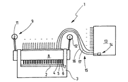
図1には、打ち抜き装置1を概略的に示した。この打ち抜き装置は、グリーンシートを打ち抜き加工する、つまりグリーンシートに孔を打ち抜くために用いられる。この打ち抜き装置1に切断プレート2が属しており、この切断プレートはフレーム3に保持されていて、かつ下工具(下型)を形成する。切断プレート2に図示していないグリーンシートが載設するようになっており、この切断プレート2は一群の切断孔を備えており、これらの切断用孔にポンチ4,5,6,7が対応配置されている。ポンチ4〜7ならびに符号を付していないさらに別のポンチは、図1には詳しく示していないポンチ支持装置8に保持されている。ポンチ支持装置8はポンチと共に上工具(上型)を形成し、この上工具はフレーム3に沿って鉛直方向可動に案内されている。グリーンシートを打ち抜き加工するために、ポンチ支持装置8は鉛直方向運動を行い、このポンチ支持装置8は、ポンチ4〜7を、少なくとも作業状態である間は、各ポンチに対応配置された切断用孔に周期的に進入させることができる。ポンチ支持装置を駆動するのに駆動装置9が役立ち、この駆動装置9は、図1では2つの偏心駆動装置11,12によって形成されており、これらの偏心駆動装置11,12は連接棒を介してポンチ支持装置8と結合されている。
FIG. 1 schematically shows a punching device 1. This punching device is used for punching a green sheet, that is, for punching holes in the green sheet. A cutting
ポンチを選択的に作業状態にするかまたは非作業状態にするために制御ユニット13が役立ち、この制御ユニット13は個々のアクチュエータ14を備えている。図2から判るように、これらのアクチュエータの出力部材は、たとえばケーブル16,17の構成をしたフレキシブルで機械的な結合手段15を介して連結手段18と結合されている。ポンチ4〜7は、ポンチ支持装置8の適当な案内孔21〜24において、単列または複列式に相並んで軸方向可動に支承されている。ポンチ4〜7は円筒形のシャフト部分58から形成されており、このシャフト部分58は、上位領域で、ポンチヘッドを形成するリング状のブシュ59によって取り囲まれている。この実施例では、ポンチヘッド59はポンチシャフト58の端部から間隔を有して配置されているので、第2のポンチ案内区分60が形成される。ブシュ59とポンチシャフト58とは、従来の形式でたとえばはんだ付けによって互いに結合されている。また一体的に成形されたポンチを設けることもできる。ブシュ59がポンチシャフトエンドと同一平面を成して終わるようにすることもでき、この場合第2の案内区分60は設けられていない。そのような実施例は図3〜図6に示した。この実施例は、本発明の思想に関して不都合に働くことはない。ポンチ4〜7はポンチヘッド59で、実質的に扁平な当接面25に当接するようになっており、この当接面25は通常横断面でU字形のポンチ支持装置8に設けられている(図3参照)。連結装置18に連結部材26,27,28,29が所属しており、これらの連結部材26〜29はそれぞれ個別的にポンチ4〜7に対応配置されている。連結部材26〜29は軸方向可動に支承されているので、連結部材26〜29は、ポンチ4〜7のヘッド59を当接面25に押し付けるか、ヘッド59を解放することができる。判りやすく図示するために連結部材29は解放位置で示した。連結部材26〜29は芯31,32,33,34の端部によって形成することができ、これらの芯31〜34はケーブル16,17,16a,17aに所属している。これらの芯31〜34の端部は、ポンチ4〜7に対して共軸的に配置されていて、かつポンチ支持装置8の上位脚部の適当な孔を通って延びている。さらにこの脚部に、ケーブル16,17,16a,17aのスリーブ36,37,38,39が取り付けられている。
A
図3には、全てのポンチおよびケーブルを代表するものとして、ケーブル16およびポンチ4を横断面図で示した。さらに図3には保持装置41を示した。この保持装置41は、たとえばU字形プロフィールの上位脚部の構成をした、定置に支承された支持体42を備えている。支持体42は、各連結部材26〜29のために案内孔43を備えており、この案内孔43に、該当する連結部材26が軸方向可動に保持されている。案内孔43は、ポンチ4と整合している。支持体42は、U字形プロフィールを有するポンチ支持装置8の両脚部の間の中間スペースに係合しており、この場合ポンチ支持装置8の鉛直方向運動は、ポンチ支持装置8が実施する打ち抜きストロークよりも大きくなっている。
In FIG. 3, the
さらにU字形プロフィールを成す保持装置41は下位脚部を備えており、この下位脚部は、ポンチ4(別の各ポンチについても同様である)のために孔44を備えており、この孔44を通ってポンチ4のポンチシャフト58が延びている。
Furthermore, the holding
ポンチ4に、有利には連結装置45が作用しており、この連結装置45はポンチ4を、図3に示した上位の昇降位置で弾性的に保持する。連結装置45は、たとえば下位のポンチ支持装置8とポンチヘッドとの間で支持作用を及ぼすばねによって、または図3に示したように、たとえばリング磁石として案内孔43に対して同心的に配置された永久磁石46によって形成することができる。永久磁石46は、ポンチ4のポンチヘッドに作用しているので、ポンチヘッドは永久磁石に固定される。
A
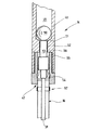
図7には、制御ユニット13の全てのアクチュエータを代表するニューマチック式のアクチュエータ14を示した。アクチュエータ14の出力部材47にケーブル16が接続されている。アクチュエータ14は、管状の基本体48によって形成されており、この基本体48にほぼ円筒形状の内室49が形成されている。端面側で内室49は円錐形の座51によって終了している。内室つまり室49に球50が配置されており、この球50の直径は内室49の直径よりも僅かに小さくなっている。座51は内室49に対して共軸的かつ中央を同じくして円筒形状の孔52に移行しており、この孔52を通って押圧ロッド53が突出している。押圧ロッド53は孔52内で軸方向可動に支承されている。球50とは反対側の端部で押圧ロッド53は芯31と結合されている。押圧ロッド53に作用する押圧ばね54は、押圧ロッド53を球50に向かって、押圧ロッド53に設けられた肩部55がリング状の対抗当接面56に当接するまで押圧する。この対抗当接面56は孔52を取り囲んでいる。室49に、図示していない電気制御式の弁が接続されており、これによって室49を意図的に圧縮空気で充填し、かつ排気することができる。
FIG. 7 shows a
記載の打ち抜き装置1は以下のように作動する。 The described punching device 1 operates as follows.
運転中に駆動装置もしくはリニア式駆動装置9がポンチ支持装置8を周期的に上下運動させ、これによってポンチは切断プレート2に載設しているグリーンシートを打ち抜く。この場合作業状態のポンチしか作動せず、非作業状態のポンチはこの運動過程に関与しない。個々のポンチの作業化および非作業化は、制御ユニット13によって詳しくは以下のようにして行われる。
During operation, the drive device or linear drive device 9 periodically moves the
制御ユニット13は、フレキシブルな結合手段15を介して個々のポンチの作業化および非作業化を制御する。このような制御は、個々のケーブル15,16,16a,17,17aの芯31〜34が前進または後退することによって行われる。これについては図3〜図6にポンチ4に基づいて示した。
The
図3では、ポンチ支持装置8が上死点に位置しており、また図4では、下方ストローク中または下死点の直前に位置している。ここではポンチ4は非作業状態である。このポンチ4に対応配置されたアクチュエータ14は排気されている。したがってばね54(図7)は押圧ロッド53を受動位置に押圧し、この受動位置では肩部55が対抗当接面56に接触している。これによってケーブル16の芯31は、後退位置に移動され、この後退位置では、芯は、図3に示したようにポンチ4のポンチシャフトエンドに接触していない。芯31がポンチシャフトエンドに接触するようにすることもできるが、この場合芯の接触は非力伝達式の接触である。ポンチ支持装置8が下方に走行する場合、図4に示したように、ポンチヘッド59は永久磁石46によって上位の位置で保持され、つまりポンチ4は下方に案内されず、グリーンシートに載設されない。ポンチ支持装置8は、ポンチ4を運動させることなしに、任意の数のストロークを実施することができる。
In FIG. 3, the
ポンチ4を作業状態にしようとすると、このポンチ4に対応配置されたアクチュエータ14が圧縮空気で負荷される。この場合球50はミリ秒範囲で押圧ロッド53の端面に押し付けられ、この押圧ロッド53を軸方向で前方に、球が座51に当接するまで押し出す。この場合芯31を形成する耐圧縮性のスプリングワイヤが、図5に示した位置に移動される。このようなスプリングワイヤの移動は、有利にはポンチ支持体8が上死点または上死点近くに位置している場合に行われる。
When the punch 4 is to be put into a working state, the
これによって連結部材26は、図5に示したように、ポンチシャフトエンド60に接近するか、またはこれに当接する。ポンチ支持装置8が、図6に示したように、支持体42に向かってポンチ4の軸方向で下死点に運動する場合、連結部材26はポンチ4のヘッド59を押圧して永久磁石46から離間させる。
As a result, the connecting
球50が押圧ロッド53を移動させる距離は、連結部材26がポンチ4のヘッドに向かって移動される距離と一致する。ポンチ支持装置8が下方運動に際してケーブル16のスリーブ36を下方へ連行するので、芯31も同様に下方運動を行い、その結果連結部材26もまたポンチ4のヘッド59を当接面25に押圧したまま保持する。したがってポンチ4は作業状態になっており、ポンチ4は作業状態を、球50が座51に押圧されている間維持する。
The distance that the
長さ誤差を補償するために、スリーブ16は、図7に示したように、押圧ばねエレメント57を備えるか、または弾性的に支承された保持体に取り付けることができる。このような補償手段は、特に球50によって急速に行われるストロークが、連結部材26がポンチ4のポンチシャフトエンド60に当接するのに必要な距離よりも僅かに大きくなっている場合に有利である。押圧ばねエレメント57によって、連結エレメント26は弾性的にポンチシャフトエンド60に対してプレロード(予荷重)をかけられ、ポンチヘッド59は当接面25に対してプレロードをかけられる。
In order to compensate for the length error, the
個々のポンチ4〜7の、アクティブな作業位置とパッシブな非作業位置との間の切換は、数ミリ秒以内で行われる。芯31は長手方向で堅固であり、かつスリーブ36を形成するフレキシブルな鋼管において少ない摩擦で支承されている。横方向で必要な構成スペースは、ポンチヘッド59の幅よりもそれ程大きくはないので、極めて小さなポンチ分割配置を達成することができる。実際の打ち抜き装置(ポンチおよびポンチ支持装置)への熱伝達は認められない。ニューマチック式のアクチュエータ14、または別形式のアクチュエータ14、たとえば電気力学式、電磁石式もしくはこれに類する形式のアクチュエータ14を使用することもできる。
The switching of the individual punches 4 to 7 between the active working position and the passive non-working position takes place within a few milliseconds. The
特に未焼成のセラミック基板を打ち抜くのに設けられた打ち抜き装置1は、複数のポンチ4〜7を備えたポンチ支持装置8を備えており、これらのポンチ4〜7は、作業状態にするためにポンチ支持装置8にロックすることができ、次いでポンチ支持装置8と共に軸方向打ち抜き運動を行う。ポンチをロックするために、遠隔操作される連結装置18が役立つ。操作運動を遠隔伝達するために、フレキシブルで機械的な結合手段、たとえば有利にはケーブル16が役立つ。
In particular, the punching device 1 provided for punching an unfired ceramic substrate includes a
1 打ち抜き装置、 2 切断プレート、 3 フレーム、 4,5,6,7 ポンチ、 8 ポンチ支持装置、 9 駆動装置、 11,12 偏心駆動装置、 13 制御ユニット、 14 アクチュエータ、 15 結合手段、 16,16a,17,17a ケーブル、 18 連結装置、 21,22,23,24 案内孔、 26,27,28,29 連結部材、 30,31,32,33,34 芯、 36,37,38,39 スリーブ、 41 保持装置、 42 支持体、 43 案内孔、 44 孔、 45 連結装置、 46 永久磁石、 47 出力部材、 48 基本体、 49 内室、 50 球、 51 座、 52 孔、 53 押圧ロッド、 54 押圧ばね、 55 肩部、 56 対抗当接面、 57 押圧ばねエレメント、 58 ポンチシャフト、 59 ヘッド、 60 案内区分 1 punching device, 2 cutting plate, 3 frame, 4, 5, 6, 7 punch, 8 punch support device, 9 drive device, 11, 12 eccentric drive device, 13 control unit, 14 actuator, 15 coupling means, 16, 16a , 17, 17a cable, 18 connecting device, 21, 22, 23, 24 guide hole, 26, 27, 28, 29 connecting member, 30, 31, 32, 33, 34 core, 36, 37, 38, 39 sleeve, 41 holding device, 42 support, 43 guide hole, 44 hole, 45 coupling device, 46 permanent magnet, 47 output member, 48 basic body, 49 inner chamber, 50 ball, 51 seat, 52 hole, 53 pressing rod, 54 pressing Spring, 55 shoulder, 56 opposing abutment surface, 57 pressure spring element, 58 puncher Doo, 59 head, 60 guide portion
Claims (16)
ポンチ支持装置(8)が設けられており、該ポンチ支持装置(8)が、駆動装置(9)と結合されており、該ポンチ支持装置(8)が、打ち抜き運動を行うようになっており、
複数のポンチ(4,5,6,7)が設けられており、これらのポンチ(4,5,6,7)が、ポンチ支持装置(8)に関して、ポンチ軸方向可動に保持されており、
制御可能な連結装置(18)が設けられており、該連結装置(18)によって、ポンチ(4,5,6,7)が、軸方向で堅固にポンチ支持装置(8)と結合されるようになっており、
制御ユニット(13)が設けられており、該制御ユニット(13)が、ポンチ支持装置(8)から離れて配置されていて、かつ連結装置(18)を運動させるための出力部材(47)を備えており、該出力部材(47)によって、ポンチ(4,5,6,7)が、作業状態または非作業状態にされるようになっており、
フレキシブルで機械的な結合手段(15)が設けられており、該結合手段(15)が、制御ユニット(13)と連結装置(18)との間に配置されており、制御ユニット(13)と連結装置(18)とが互いに結合されるようになっていることを特徴とする、打ち抜き装置。 For example, in a punching device for punching green sheets,
A punch support device (8) is provided, the punch support device (8) is coupled to a drive device (9), and the punch support device (8) is adapted to perform a punching movement. ,
A plurality of punches (4, 5, 6, 7) are provided, and these punches (4, 5, 6, 7) are held movable in the punch axial direction with respect to the punch support device (8),
A controllable coupling device (18) is provided by which the punch (4, 5, 6, 7) is firmly coupled to the punch support device (8) in the axial direction. And
A control unit (13) is provided, the control unit (13) being arranged away from the punch support device (8) and an output member (47) for moving the coupling device (18). The punch (4, 5, 6, 7) is put into a working state or a non-working state by the output member (47).
Flexible and mechanical coupling means (15) are provided, the coupling means (15) being arranged between the control unit (13) and the coupling device (18), and the control unit (13) Punching device, characterized in that the coupling device (18) is connected to each other.
Applications Claiming Priority (1)
| Application Number | Priority Date | Filing Date | Title |
|---|---|---|---|
| DE2003128776 DE10328776B3 (en) | 2003-06-25 | 2003-06-25 | Punching device for flat objects |
Publications (3)
| Publication Number | Publication Date |
|---|---|
| JP2005014207A true JP2005014207A (en) | 2005-01-20 |
| JP2005014207A5 JP2005014207A5 (en) | 2007-02-15 |
| JP4638696B2 JP4638696B2 (en) | 2011-02-23 |
Family
ID=33515086
Family Applications (1)
| Application Number | Title | Priority Date | Filing Date |
|---|---|---|---|
| JP2004185337A Expired - Fee Related JP4638696B2 (en) | 2003-06-25 | 2004-06-23 | Punching device for flat material |
Country Status (8)
| Country | Link |
|---|---|
| US (1) | US7726553B2 (en) |
| JP (1) | JP4638696B2 (en) |
| KR (1) | KR100625002B1 (en) |
| CN (1) | CN100340384C (en) |
| DE (1) | DE10328776B3 (en) |
| FR (1) | FR2856616B1 (en) |
| IT (1) | ITTO20040422A1 (en) |
| TW (1) | TWI265852B (en) |
Cited By (1)
| Publication number | Priority date | Publication date | Assignee | Title |
|---|---|---|---|---|
| TWI723684B (en) * | 2019-12-17 | 2021-04-01 | 易華電子股份有限公司 | Mold for drilling a tape-type flexible circuit board |
Families Citing this family (4)
| Publication number | Priority date | Publication date | Assignee | Title |
|---|---|---|---|---|
| EP1993335B1 (en) * | 2007-05-14 | 2012-03-14 | Groz-Beckert KG | Stamping device with exchangeable stamp and variable stamping pattern |
| US20090091424A1 (en) * | 2007-10-05 | 2009-04-09 | Manfred Rietzler | Transponder inlay for a personal document and method of manufacturing same |
| CN103433343A (en) * | 2013-08-19 | 2013-12-11 | 苏州市胜能弹簧五金制品有限公司 | Linear punching device suitable for punching thin die plate |
| CN115415408B (en) * | 2022-09-05 | 2023-09-26 | 江苏东方瑞吉能源装备有限公司 | Pipe connecting cover plate pressing die, production method thereof and liner pipe cover plate forming method |
Citations (6)
| Publication number | Priority date | Publication date | Assignee | Title |
|---|---|---|---|---|
| JPS5319553U (en) * | 1976-07-30 | 1978-02-20 | ||
| US4685613A (en) * | 1986-09-16 | 1987-08-11 | Frank Schambre | Reciprocable tool mounting module |
| JPS645795A (en) * | 1987-06-30 | 1989-01-10 | Komatsu Mfg Co Ltd | Piercing device |
| JPH01240299A (en) * | 1988-03-18 | 1989-09-25 | Fujitsu Ltd | Wiring base plate manufacturing device |
| JPH03131499A (en) * | 1989-10-10 | 1991-06-05 | Internatl Business Mach Corp <Ibm> | Puunching device and method |
| JP2000015358A (en) * | 1998-07-07 | 2000-01-18 | Press Kogyo Co Ltd | Pierced earing hole punching unit and pierced earing hole punching method using it |
Family Cites Families (23)
| Publication number | Priority date | Publication date | Assignee | Title |
|---|---|---|---|---|
| US2028638A (en) * | 1929-06-17 | 1936-01-21 | Associated Electric Lab Inc | Means for controlling card perforating machines |
| US2044707A (en) * | 1931-05-16 | 1936-06-16 | Remington Rand Inc | Card punching machine |
| BE403825A (en) * | 1933-02-02 | |||
| US2124178A (en) * | 1936-10-07 | 1938-07-19 | Remington Rand Inc | Statistical card punch |
| US3137441A (en) * | 1961-12-26 | 1964-06-16 | Ibm | Punching device |
| US3170390A (en) * | 1962-03-29 | 1965-02-23 | Jack M Wagner | Apparatus for incising and imprinting information |
| US3263914A (en) * | 1964-01-03 | 1966-08-02 | Electronic Assistance Corp | Punching device |
| US3311297A (en) * | 1965-04-06 | 1967-03-28 | Sperry Rand Corp | Selective punching mechanism |
| GB1222961A (en) * | 1967-01-13 | 1971-02-17 | Associated Perforators And Wea | Improvements in or relating to apparatus for selectively reciprocating a number of tools to form a pattern |
| US3510056A (en) * | 1967-10-02 | 1970-05-05 | Source Data Automation Inc | Data recording device |
| US3508706A (en) * | 1968-01-30 | 1970-04-28 | Rusco Ind Inc | Code perforating device |
| US3633817A (en) * | 1969-12-29 | 1972-01-11 | Entwistle Co | Data punching machine |
| FR2311635A1 (en) * | 1975-05-23 | 1976-12-17 | Boudeville Marc | Steel programme tap punch for circular loom - acts on paper punch tape data has ratchet tape feed and pneumatic sensors |
| KR920010772B1 (en) * | 1987-07-08 | 1992-12-17 | 우시오 가부시기가이샤 | Punching device for thin plates and punching units used with punching device |
| JPH02124295A (en) * | 1988-10-28 | 1990-05-11 | Ushio Kk | Multishaft boring device |
| JPH0813387B2 (en) * | 1990-11-08 | 1996-02-14 | 株式会社三協マニテック | Punching board punching machine |
| CN2110556U (en) * | 1992-01-08 | 1992-07-22 | 赵放放 | Hand electric percussive tool |
| CN1025873C (en) * | 1992-12-26 | 1994-09-07 | 杭州经纬电气自动化公司 | Transverse punching type card automatic puncher |
| JP2673117B2 (en) * | 1995-08-31 | 1997-11-05 | ユーエイチティー株式会社 | Drilling system |
| FR2750912B1 (en) * | 1996-07-15 | 1998-11-06 | Automa Tech Sa | PRINTED CIRCUIT PLATE PUNCHING MACHINE |
| DE19815400C2 (en) * | 1998-04-06 | 2002-02-07 | Max Planck Gesellschaft | Device for taking samples from polymeric carrier materials |
| DE19825842A1 (en) * | 1998-06-10 | 1999-12-16 | Schuler Pressen Gmbh & Co | Press for the production of variable processing samples |
| CN2509817Y (en) * | 2001-09-30 | 2002-09-04 | 富伟精机股份有限公司 | Punching equipment for printed circuit board |
-
2003
- 2003-06-25 DE DE2003128776 patent/DE10328776B3/en not_active Expired - Fee Related
-
2004
- 2004-06-18 US US10/870,534 patent/US7726553B2/en not_active Expired - Fee Related
- 2004-06-23 JP JP2004185337A patent/JP4638696B2/en not_active Expired - Fee Related
- 2004-06-23 IT ITTO20040422 patent/ITTO20040422A1/en unknown
- 2004-06-23 FR FR0406849A patent/FR2856616B1/en not_active Expired - Fee Related
- 2004-06-24 KR KR1020040047437A patent/KR100625002B1/en not_active IP Right Cessation
- 2004-06-24 CN CNB2004100616946A patent/CN100340384C/en not_active Expired - Fee Related
- 2004-06-24 TW TW93118188A patent/TWI265852B/en not_active IP Right Cessation
Patent Citations (6)
| Publication number | Priority date | Publication date | Assignee | Title |
|---|---|---|---|---|
| JPS5319553U (en) * | 1976-07-30 | 1978-02-20 | ||
| US4685613A (en) * | 1986-09-16 | 1987-08-11 | Frank Schambre | Reciprocable tool mounting module |
| JPS645795A (en) * | 1987-06-30 | 1989-01-10 | Komatsu Mfg Co Ltd | Piercing device |
| JPH01240299A (en) * | 1988-03-18 | 1989-09-25 | Fujitsu Ltd | Wiring base plate manufacturing device |
| JPH03131499A (en) * | 1989-10-10 | 1991-06-05 | Internatl Business Mach Corp <Ibm> | Puunching device and method |
| JP2000015358A (en) * | 1998-07-07 | 2000-01-18 | Press Kogyo Co Ltd | Pierced earing hole punching unit and pierced earing hole punching method using it |
Cited By (1)
| Publication number | Priority date | Publication date | Assignee | Title |
|---|---|---|---|---|
| TWI723684B (en) * | 2019-12-17 | 2021-04-01 | 易華電子股份有限公司 | Mold for drilling a tape-type flexible circuit board |
Also Published As
| Publication number | Publication date |
|---|---|
| ITTO20040422A1 (en) | 2004-09-23 |
| FR2856616B1 (en) | 2009-06-12 |
| CN100340384C (en) | 2007-10-03 |
| CN1575947A (en) | 2005-02-09 |
| US7726553B2 (en) | 2010-06-01 |
| FR2856616A1 (en) | 2004-12-31 |
| KR100625002B1 (en) | 2006-09-20 |
| KR20050001398A (en) | 2005-01-06 |
| JP4638696B2 (en) | 2011-02-23 |
| US20040261594A1 (en) | 2004-12-30 |
| DE10328776B3 (en) | 2005-01-27 |
| TWI265852B (en) | 2006-11-11 |
| TW200523084A (en) | 2005-07-16 |
Similar Documents
| Publication | Publication Date | Title |
|---|---|---|
| JP2000505530A (en) | Electromagnetic directional switching valve | |
| JP2006297416A (en) | Pressing device for fixing nut to pipe material | |
| JP4638696B2 (en) | Punching device for flat material | |
| JP3345400B2 (en) | Hydraulic drive mechanism for slides on forging presses or machines | |
| EP1892082A2 (en) | Linear motor mounted press machine and press working method | |
| JPH10309680A (en) | Drill and chisel device | |
| CZ202999A3 (en) | Press, particularly for punching sheets or another flat material with holes distributed in pattern | |
| KR100391453B1 (en) | Piercing device for press system | |
| JP3709327B2 (en) | Forging equipment | |
| JP4639184B2 (en) | Double guide type pressurized fluid distributor | |
| KR100471246B1 (en) | Piercing device for press system | |
| JP2004338035A (en) | Parallel opening/closing chuck | |
| CN211101341U (en) | Small-size mound thick system of prestressing force steel bar | |
| US787707A (en) | Electric tool-driver. | |
| CN100376380C (en) | Mechanical forging press | |
| JPH01289516A (en) | Form punching apparatus | |
| JP5044200B2 (en) | Wire rod chuck device and forging machine | |
| EP1270108B1 (en) | Punch press | |
| FR2630938A1 (en) | Punching device | |
| JPS5856068Y2 (en) | Axial feed cylinder | |
| SU1232623A2 (en) | Electromagnetic gripping device | |
| JP2005224805A (en) | Apparatus and method for compacting powder | |
| SU1310297A1 (en) | Device for fitting clips on filled package | |
| SU1011317A1 (en) | High-speed hammer | |
| SU1362605A1 (en) | Induction device for disassembly of press-fitted joints |
Legal Events
| Date | Code | Title | Description |
|---|---|---|---|
| A521 | Request for written amendment filed |
Free format text: JAPANESE INTERMEDIATE CODE: A523 Effective date: 20061227 |
|
| A621 | Written request for application examination |
Free format text: JAPANESE INTERMEDIATE CODE: A621 Effective date: 20061227 |
|
| A131 | Notification of reasons for refusal |
Free format text: JAPANESE INTERMEDIATE CODE: A131 Effective date: 20091211 |
|
| A601 | Written request for extension of time |
Free format text: JAPANESE INTERMEDIATE CODE: A601 Effective date: 20100310 |
|
| A602 | Written permission of extension of time |
Free format text: JAPANESE INTERMEDIATE CODE: A602 Effective date: 20100315 |
|
| A601 | Written request for extension of time |
Free format text: JAPANESE INTERMEDIATE CODE: A601 Effective date: 20100412 |
|
| A602 | Written permission of extension of time |
Free format text: JAPANESE INTERMEDIATE CODE: A602 Effective date: 20100415 |
|
| A521 | Request for written amendment filed |
Free format text: JAPANESE INTERMEDIATE CODE: A523 Effective date: 20100511 |
|
| A02 | Decision of refusal |
Free format text: JAPANESE INTERMEDIATE CODE: A02 Effective date: 20100707 |
|
| A521 | Request for written amendment filed |
Free format text: JAPANESE INTERMEDIATE CODE: A523 Effective date: 20101004 |
|
| A911 | Transfer to examiner for re-examination before appeal (zenchi) |
Free format text: JAPANESE INTERMEDIATE CODE: A911 Effective date: 20101018 |
|
| TRDD | Decision of grant or rejection written | ||
| A01 | Written decision to grant a patent or to grant a registration (utility model) |
Free format text: JAPANESE INTERMEDIATE CODE: A01 Effective date: 20101112 |
|
| A01 | Written decision to grant a patent or to grant a registration (utility model) |
Free format text: JAPANESE INTERMEDIATE CODE: A01 |
|
| A61 | First payment of annual fees (during grant procedure) |
Free format text: JAPANESE INTERMEDIATE CODE: A61 Effective date: 20101126 |
|
| FPAY | Renewal fee payment (event date is renewal date of database) |
Free format text: PAYMENT UNTIL: 20131203 Year of fee payment: 3 |
|
| R150 | Certificate of patent or registration of utility model |
Free format text: JAPANESE INTERMEDIATE CODE: R150 |
|
| R250 | Receipt of annual fees |
Free format text: JAPANESE INTERMEDIATE CODE: R250 |
|
| LAPS | Cancellation because of no payment of annual fees |