JP2005002982A - Variable miller cycle engine - Google Patents
Variable miller cycle engine Download PDFInfo
- Publication number
- JP2005002982A JP2005002982A JP2003297924A JP2003297924A JP2005002982A JP 2005002982 A JP2005002982 A JP 2005002982A JP 2003297924 A JP2003297924 A JP 2003297924A JP 2003297924 A JP2003297924 A JP 2003297924A JP 2005002982 A JP2005002982 A JP 2005002982A
- Authority
- JP
- Japan
- Prior art keywords
- timing
- variable
- normal
- cam
- cycle engine
- Prior art date
- Legal status (The legal status is an assumption and is not a legal conclusion. Google has not performed a legal analysis and makes no representation as to the accuracy of the status listed.)
- Pending
Links
Images
Classifications
-
- Y—GENERAL TAGGING OF NEW TECHNOLOGICAL DEVELOPMENTS; GENERAL TAGGING OF CROSS-SECTIONAL TECHNOLOGIES SPANNING OVER SEVERAL SECTIONS OF THE IPC; TECHNICAL SUBJECTS COVERED BY FORMER USPC CROSS-REFERENCE ART COLLECTIONS [XRACs] AND DIGESTS
- Y02—TECHNOLOGIES OR APPLICATIONS FOR MITIGATION OR ADAPTATION AGAINST CLIMATE CHANGE
- Y02T—CLIMATE CHANGE MITIGATION TECHNOLOGIES RELATED TO TRANSPORTATION
- Y02T10/00—Road transport of goods or passengers
- Y02T10/10—Internal combustion engine [ICE] based vehicles
- Y02T10/12—Improving ICE efficiencies
Landscapes
- Valve-Gear Or Valve Arrangements (AREA)
- Valve Device For Special Equipments (AREA)
- Output Control And Ontrol Of Special Type Engine (AREA)
Abstract
Description
複数の吸気弁を持つ4サイクルエンジンの、一方の吸気弁を通常のバルブタイミングで開閉し、もう一方の吸気弁のバルブタイミングを可変させて開閉することで、高出力と低燃費を両立した可変ミラーサイクルエンジンを得る事ができる。
可変できる側の吸気弁のバルブタイミングを遅い方に調節すると、圧縮行程を短くした遅閉じミラーサイクルで高効率運転ができる。早い方に調節すると吸気の充填効率が上がり高出力を得ることができる。バルブタイミングを調節することで回転数を調整できるので、スロットルバルブを省略または大きく開けられるので、ポンピングロスが減り、燃費が良くなる。過度なエンジンブレーキも小さくできる。希薄燃焼にする必要がないので通常の触媒で排気の浄化をすることができる。
しかし、よく用いられるOHCやDOHCのバルブ駆動では、複数の吸気弁は同一線上のカ厶シャフトで駆動するので、直列2気筒以上では、通常のバルブタイミングの吸気弁と可変できる吸気弁が交互に現れる事になるので、駆動できる構造にすることが難しかった。
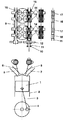
通常タイミング筒状カム13を、カム駆動シャフト11のスプライン部16で駆動し、可変タイミング筒状カム14を、カム駆動シャフト11のスクリュースプライン部17で駆動し、カム駆動シャフト11を軸方向に移動させれば実現できる。しかし、カム駆動シャフト11は、スプライン穴とスクリュースプライン穴の両方を通す事ができないので、組立てできない。そこで、通常タイミング筒状カム13と可変タイミング筒状カム14の穴には、スプラインとスクリュースプラインの両方を加工しておけば、カム駆動シャフト11を通して組立てられるので、実現可能となる。In a four-cycle engine with multiple intake valves, one intake valve is opened and closed at normal valve timing, and the other intake valve is opened and closed with variable valve timing to achieve both high output and low fuel consumption. You can get a mirror cycle engine.
By adjusting the valve timing of the intake valve on the variable side to the slower one, high-efficiency operation can be achieved with a delayed closed mirror cycle with a shortened compression stroke. Adjusting to the earlier speed increases the charging efficiency of the intake air and can provide a high output. Since the number of revolutions can be adjusted by adjusting the valve timing, the throttle valve can be omitted or greatly opened, thereby reducing the pumping loss and improving the fuel efficiency. Excessive engine braking can be reduced. Since it is not necessary to use lean combustion, exhaust gas can be purified with a normal catalyst.
However, in the commonly used OHC and DOHC valve drive, a plurality of intake valves are driven by the same shaft, so in two or more cylinders in series, the normal valve timing intake valve and the variable intake valve are alternated. Because it will appear, it was difficult to make a structure that can be driven.
The normal timing
エンジン engine
従来のミラーサイクルエンジンは、圧縮・膨張比が一定で圧縮行程が短いので、排気量の割に燃費は良いが、出力は少なかった。カム位相角度可変装置で、吸気側カムを遅閉じに可変させるエンジンでは、吸気弁を開かないうちにピストンが下がるのでポンピングロスが生ずる。 The conventional Miller cycle engine has a constant compression / expansion ratio and a short compression stroke. Therefore, the fuel efficiency is good for the displacement, but the output is small. In an engine in which the intake side cam is changed to be delayed closed by the cam phase angle variable device, the piston is lowered before the intake valve is opened, and therefore a pumping loss occurs.
複数の吸気弁を持つ4サイクルエンジンの、一方の吸気弁を通常のバルブタイミングで開閉し、もう一方の吸気弁のバルブタイミングを可変させて開閉することで、高出力と低燃費を両立した可変ミラーサイクルエンジンを得る事ができる。
しかし、よく用いられるOHCやDOHCのバルブ駆動では、複数の吸気弁は同一線上のカムシャフトで駆動するので、直列2気筒以上では、通常のバルブタイミングの吸気弁と可変できる吸気弁が交互に現れる事になるので、駆動できる構造にすることが難しかった。In a four-cycle engine with multiple intake valves, one intake valve is opened and closed at normal valve timing, and the other intake valve is opened and closed with variable valve timing to achieve both high output and low fuel consumption. You can get a mirror cycle engine.
However, in the commonly used OHC and DOHC valve drive, a plurality of intake valves are driven by camshafts on the same line, so that in the case of two or more cylinders in series, the intake valve that can be varied and the intake valve that can be varied appear alternately. Therefore, it was difficult to make a structure that can be driven.
通常タイミング筒状カム13を、カム駆動シャフト11のスプライン部16で駆動し、可変タイミング筒状カム14を、カ厶駆動シャフト11のスクリュースプライン部17で駆動し、カ厶駆動シャフト11を軸方向に移動させれば実現できる。しかし、カム駆動シャフト11は、スプライン穴とスクリュースプライン穴の両方を通す事ができないので、組立てできない。そこで、通常タイミング筒状カム13と可変タイミング筒状カ厶14の穴には、スプラインとスクリュースプラインの両方を加工しておけば、カ厶駆動シャフト11を通して組立てられるので、実現可能となる。 The normal timing
可変できる側の吸気弁のバルブタイミングを遅い方に調節すると、圧縮行程を短くした遅閉じミラーサイクルで高効率運転ができる。早い方に調節すると吸気の充填効率が上がり高出力を得ることができる。バルブタイミングを調節することで回転数を調整できるので、スロットルバルブを省略または大きく開けられるので、ポンピングロスが減り、燃費が良くなる。過度なエンジンブレーキも小さくできる。希薄燃焼にする必要がないので通常の触媒で排気の浄化をすることができる。 By adjusting the valve timing of the intake valve on the variable side to the slower one, high-efficiency operation can be achieved with a delayed closed mirror cycle with a shortened compression stroke. Adjusting to the earlier speed increases the charging efficiency of the intake air and can provide a high output. Since the number of revolutions can be adjusted by adjusting the valve timing, the throttle valve can be omitted or opened widely, so that the pumping loss is reduced and the fuel consumption is improved. Excessive engine braking can be reduced. Since it is not necessary to use lean combustion, exhaust gas can be purified with a normal catalyst.
1.ピストン
2.シリンダー
3.コンロッド
4.クランク
5.吸気弁
6.排気弁
7.吸気ポート
8.排気ポート
9.排気側カ厶シャフト
10.軸受け
11.カム駆動シャフト
12.スプロケット
13.通常タイミング筒状カム
14.可変タイミング筒状カム
15.軸受け
16.スプライン部
17.スクリュースプライン部1. Piston 2. Cylinder 3. Connecting rod Crank 5. Intake valve 6. 6. Exhaust valve Intake
Claims (1)
通常タイミング筒状カム13を、カ厶駆動シャフト11のスプライン部16で駆動し、可変タイミング筒状カム14を、カム駆動シャフト11のスクリュースプライン部17で駆動し、カム駆動シャフト11を軸方向に移動させれば実現できる。しかし、カ厶駆動シャフト11は、スプライン穴とスクリュースプライン穴の両方を通す事ができないので、組立てできない。そこで、通常タイミング筒状カ厶13と可変タイミング筒状カ厶14の穴には、スプラインとスクリュースプラインの両方を加工しておけば、カム駆動シャフト11を通して組立てられるので、実現可能となる。In a four-cycle engine with multiple intake valves, one intake valve is opened and closed at normal valve timing, and the other intake valve is opened and closed with variable valve timing to achieve both high output and low fuel consumption. You can get a mirror cycle engine.
The normal timing cylindrical cam 13 is driven by the spline portion 16 of the cam drive shaft 11, the variable timing cylindrical cam 14 is driven by the screw spline portion 17 of the cam drive shaft 11, and the cam drive shaft 11 is axially driven. This can be achieved by moving it. However, the collar drive shaft 11 cannot be assembled because it cannot pass through both the spline hole and the screw spline hole. Therefore, if both the spline and the screw spline are machined in the holes of the normal timing cylindrical collar 13 and the variable timing cylindrical collar 14, it can be realized through the cam drive shaft 11, so that it can be realized.
Priority Applications (1)
| Application Number | Priority Date | Filing Date | Title |
|---|---|---|---|
| JP2003297924A JP2005002982A (en) | 2003-07-18 | 2003-07-18 | Variable miller cycle engine |
Applications Claiming Priority (1)
| Application Number | Priority Date | Filing Date | Title |
|---|---|---|---|
| JP2003297924A JP2005002982A (en) | 2003-07-18 | 2003-07-18 | Variable miller cycle engine |
Publications (2)
| Publication Number | Publication Date |
|---|---|
| JP2005002982A true JP2005002982A (en) | 2005-01-06 |
| JP2005002982A5 JP2005002982A5 (en) | 2005-05-26 |
Family
ID=34101141
Family Applications (1)
| Application Number | Title | Priority Date | Filing Date |
|---|---|---|---|
| JP2003297924A Pending JP2005002982A (en) | 2003-07-18 | 2003-07-18 | Variable miller cycle engine |
Country Status (1)
| Country | Link |
|---|---|
| JP (1) | JP2005002982A (en) |
Cited By (1)
| Publication number | Priority date | Publication date | Assignee | Title |
|---|---|---|---|---|
| JP5510610B2 (en) * | 2011-04-15 | 2014-06-04 | トヨタ自動車株式会社 | Engine control device |
-
2003
- 2003-07-18 JP JP2003297924A patent/JP2005002982A/en active Pending
Cited By (3)
| Publication number | Priority date | Publication date | Assignee | Title |
|---|---|---|---|---|
| JP5510610B2 (en) * | 2011-04-15 | 2014-06-04 | トヨタ自動車株式会社 | Engine control device |
| JPWO2012140779A1 (en) * | 2011-04-15 | 2014-07-28 | トヨタ自動車株式会社 | Engine control device |
| US8869772B2 (en) | 2011-04-15 | 2014-10-28 | Toyota Jidosha Kabushiki Kaisha | Engine control apparatus |
Similar Documents
| Publication | Publication Date | Title |
|---|---|---|
| KR101396736B1 (en) | Internal combustion engine with variable valve gear | |
| US5205251A (en) | Rotary valve for internal combustion engine | |
| JP4873194B2 (en) | Engine with variable valve system | |
| BR0312300A (en) | Asymmetric rotary motor with continuous torque reverse displacement | |
| EP1571301A3 (en) | Valve characteristic changing apparatus for internal combustion engine | |
| JP2011099392A (en) | Variable valve gear for internal combustion engine | |
| JP6285301B2 (en) | Control device for internal combustion engine | |
| BRPI0408638A (en) | device for variable actuation of internal combustion engine gas exchange valves | |
| JP2010196487A (en) | Engine with variable valve gear | |
| US8651075B2 (en) | Engine assembly including camshaft with independent cam phasing | |
| JP2011032989A (en) | Atkinson cycle engine | |
| JP2004132296A (en) | Narrow-angle v-type engine | |
| JP2005002982A (en) | Variable miller cycle engine | |
| US6189497B1 (en) | Variable valve lift and timing camshaft support mechanism for internal combustion engines | |
| JP6450474B2 (en) | Internal combustion engine | |
| JP4365304B2 (en) | Variable cycle device for internal combustion engine | |
| JP2020101167A (en) | Control system of two-stage expansion type engine | |
| US7574982B2 (en) | Engine cycles | |
| BRPI0419031A (en) | apparatus for an internal combustion engine | |
| JP6450475B2 (en) | Internal combustion engine | |
| JP2008057516A (en) | Cam phase variable type internal combustion engine | |
| JP2007127041A (en) | Four-cycle engine with internal egr system | |
| JP5516896B2 (en) | Internal combustion engine with variable valve gear | |
| SU1668713A1 (en) | Four-stroke internal combustion engine | |
| US20050087157A1 (en) | Internal combustion engine and camshaft thereof |