JP2004529392A - Windows, methods of displaying characters on windows, and image display panels - Google Patents
Windows, methods of displaying characters on windows, and image display panels Download PDFInfo
- Publication number
- JP2004529392A JP2004529392A JP2003503924A JP2003503924A JP2004529392A JP 2004529392 A JP2004529392 A JP 2004529392A JP 2003503924 A JP2003503924 A JP 2003503924A JP 2003503924 A JP2003503924 A JP 2003503924A JP 2004529392 A JP2004529392 A JP 2004529392A
- Authority
- JP
- Japan
- Prior art keywords
- image display
- display panel
- window
- state
- windows
- Prior art date
- Legal status (The legal status is an assumption and is not a legal conclusion. Google has not performed a legal analysis and makes no representation as to the accuracy of the status listed.)
- Pending
Links
Images


Classifications
-
- E—FIXED CONSTRUCTIONS
- E06—DOORS, WINDOWS, SHUTTERS, OR ROLLER BLINDS IN GENERAL; LADDERS
- E06B—FIXED OR MOVABLE CLOSURES FOR OPENINGS IN BUILDINGS, VEHICLES, FENCES OR LIKE ENCLOSURES IN GENERAL, e.g. DOORS, WINDOWS, BLINDS, GATES
- E06B9/00—Screening or protective devices for wall or similar openings, with or without operating or securing mechanisms; Closures of similar construction
- E06B9/24—Screens or other constructions affording protection against light, especially against sunshine; Similar screens for privacy or appearance; Slat blinds
-
- G—PHYSICS
- G09—EDUCATION; CRYPTOGRAPHY; DISPLAY; ADVERTISING; SEALS
- G09F—DISPLAYING; ADVERTISING; SIGNS; LABELS OR NAME-PLATES; SEALS
- G09F9/00—Indicating arrangements for variable information in which the information is built-up on a support by selection or combination of individual elements
- G09F9/30—Indicating arrangements for variable information in which the information is built-up on a support by selection or combination of individual elements in which the desired character or characters are formed by combining individual elements
- G09F9/35—Indicating arrangements for variable information in which the information is built-up on a support by selection or combination of individual elements in which the desired character or characters are formed by combining individual elements being liquid crystals
-
- E—FIXED CONSTRUCTIONS
- E06—DOORS, WINDOWS, SHUTTERS, OR ROLLER BLINDS IN GENERAL; LADDERS
- E06B—FIXED OR MOVABLE CLOSURES FOR OPENINGS IN BUILDINGS, VEHICLES, FENCES OR LIKE ENCLOSURES IN GENERAL, e.g. DOORS, WINDOWS, BLINDS, GATES
- E06B9/00—Screening or protective devices for wall or similar openings, with or without operating or securing mechanisms; Closures of similar construction
- E06B9/24—Screens or other constructions affording protection against light, especially against sunshine; Similar screens for privacy or appearance; Slat blinds
- E06B2009/2464—Screens or other constructions affording protection against light, especially against sunshine; Similar screens for privacy or appearance; Slat blinds featuring transparency control by applying voltage, e.g. LCD, electrochromic panels
-
- G—PHYSICS
- G02—OPTICS
- G02F—OPTICAL DEVICES OR ARRANGEMENTS FOR THE CONTROL OF LIGHT BY MODIFICATION OF THE OPTICAL PROPERTIES OF THE MEDIA OF THE ELEMENTS INVOLVED THEREIN; NON-LINEAR OPTICS; FREQUENCY-CHANGING OF LIGHT; OPTICAL LOGIC ELEMENTS; OPTICAL ANALOGUE/DIGITAL CONVERTERS
- G02F1/00—Devices or arrangements for the control of the intensity, colour, phase, polarisation or direction of light arriving from an independent light source, e.g. switching, gating or modulating; Non-linear optics
- G02F1/01—Devices or arrangements for the control of the intensity, colour, phase, polarisation or direction of light arriving from an independent light source, e.g. switching, gating or modulating; Non-linear optics for the control of the intensity, phase, polarisation or colour
- G02F1/13—Devices or arrangements for the control of the intensity, colour, phase, polarisation or direction of light arriving from an independent light source, e.g. switching, gating or modulating; Non-linear optics for the control of the intensity, phase, polarisation or colour based on liquid crystals, e.g. single liquid crystal display cells
- G02F1/133—Constructional arrangements; Operation of liquid crystal cells; Circuit arrangements
- G02F1/1333—Constructional arrangements; Manufacturing methods
- G02F1/1334—Constructional arrangements; Manufacturing methods based on polymer dispersed liquid crystals, e.g. microencapsulated liquid crystals
Abstract
Description
【技術分野】
【0001】
本発明は、窓、キャラクターを表示する、特に窓に情報を表示する方法に関するものであり、また、画像表示パネルに関するものである。
【背景技術】
【0002】
情報を窓に表示すること、時に、店や銀行の窓に表示することが所望されており、例えば、そのような情報は、店のオーナーからの利用可能なサービスや品物のリスト及びそれらの現在の値段を含み得る。また、このような情報は、特定の日、或いは、特定の週、或いはその他の期間に、特別奉仕品(サービス)に関する情報も含み得る。このような特別奉仕品は、日毎、週毎、時間で頻繁に変更されるため、公衆に特別奉仕品やその他の情報を知らせる窓の表示は、容易にすぐに変更可能なものとすべきである。一般に、このような情報を表示する唯一の満足のいく方法は、ポスター、即ち、ショーウィンドーのガラス窓の内面に貼ったポスターである。このようなポスターは、多くの欠点を持ち、特に、店のウィンドウ(即ちショーウィンドウ)の窓ガラスの、最大の注目を惹く領域にポスターが置かれた場合に、ショーウィンドーのディスプレイ(陳列)の商品に対する一般人の視線を遮るような窓の領域にずっと置かれることとなる。これは好ましくない。ポスターのさらなる欠点は、ポスターに上に表示された情報が、更新、変更されるたびに、既存のポスターを新たなポスターで置き換える必要があることである。これは非常に困難な仕事であり、特に、ショーウィンドウの陳列エリアは、比較的制限されたエリアであり、及び/または、完全に商品を表示するために利用されている場合には困難な仕事である。ポスターで提示される特別な奉仕の申し出や情報が頻繁に更新されたり変更されたりするものである場合には、極めて深刻な問題となる。
【0003】
従って、前述の諸課題を克服するようなキャラクター及び/または情報を表示し得るような窓が必要である。また、キャラクター及び/または情報を表示する方法も必要である。
【0004】
本発明は、このような窓や方法を提供することを目的とし、また、画像表示パネル(visual display panel)の提供も目的とする。
【0005】
本発明によれば、画像表示パネルが窓に固定され、画像表示パネルが行及び列のマトリックスで構成された複数の個別にアドレス可能な画素を含み、前記画素は、交互かつ選択的に、少なくとも2つの状態で操作可能であり、前記状態は、光が前記画像表示パネルを通って透過するための第1の状態と、光が散乱、分散、反射、或いは遮られる第2の状態とを含み、それ故に、前記画素のうちの少なくとも1つを前記第2の状態で選択的に操作可能であり、表示されるべきキャラクターを形成することによって、少なくとも1つのキャラクターを前記画像表示パネル上に選択的に表示することができ、前記第1の状態の前記画素によって画像表示パネルを通して視覚のアクセスを提供するような、窓ガラスを含む窓が提供される。
【0006】
本発明のある実施態様では、前記画像表示パネルの面積は前記窓ガラスの面積とほぼ同じである。或いは、前記画像表示パネルの面積は前記窓ガラスの面積より小さい。
【0007】
本発明の他の実施態様では、前記窓ガラスが前記画像表示パネルの一部を形成する。或いは、画像表示パネルが前記窓ガラスの一部を形成する。
【0008】
好適には、前記画像表示パネルが前記窓ガラスとほぼ並行に置かれる。また、前記画像表示パネルを前記窓ガラスに貼り合わす、即ち積層させることが有利である。
【0009】
本発明のある実施態様では、前記窓ガラスは、単一構造(単一ガラス構造;single glaze construction)の窓からなる窓ガラスである。前記画像表示パネルを単一構造の窓からなる窓ガラスの内面に固定することが好適である。或いは、前記ガラス窓が、二重構造の窓の窓ガラスであり、望ましくは、前記画像表示パネルは、二重構造(2重ガラス構造;double glaze construction) の前記窓の内面と外面との間に規定される空洞に配置する。また、前記画像表示パネルを二重構造の前記窓の内面に固定することが好適である。
【0010】
本発明のある実施態様では、前記画像表示パネルが電気−光学媒体を含む。前記画像表示パネルは、透明な素材からなる一対のパネル基板を含み、前記電気−光学媒体は、前記パネル基板のそれぞれの間にはさまれて配置することが有利である。前記パネル基板の1つは複数の行電極でパターン形成され、前記パネル基板のその他のものは複数の列電極でパターン形成され、それ故に、前記行及び列電極のそれぞれは前記画素を規定するために協働して動作する、ことが好適である。理想的には、前記行及び列電極を透明な素材からなるものとする。
【0011】
本発明のある実施態様では、それぞれの前記パネル基板上の前記行及び列電極は、それぞれの前記パネル基板上に形成されているインジウムスズ酸化物(ITO)の層でパターン形成される。
【0012】
本発明のある実施態様では、それぞれの前記パネル基板上の前記行及び列電極は、それぞれのパターン形成された領域を規定し、前記画素を形成するために協働(co-operating)で動作即ち同時に動作するときに、前記パターン形成された領域の各々は、前記パターン形成されたそれぞれの領域の各々に共通であるような、共通のパターン形成された領域を規定し、前記画素は、前記共通のパターン形成された領域の中に規定されている。前記電気−光学媒体を前記共通のパターン形成されている領域の中に含ませることが好適である。
【0013】
本発明のある実施態様では、少なくとも1つのトラック支持部(track carrying portion)は前記基板の各々の前記パターン形成された領域から延在し、接続手段は前記トラック支持部の各々に延びており、複数のトラックは、前記接続手段を通じて前記電極のアドレッシングをするために、対応する前記基板の前記電極を対応する前記接続手段に接続するため、前記トラック支持部の各々でパターン形成されている。好適には、前記トラック支持部の各々の前記接続手段は、前記トラック支持部の端部に向けて配置される。また、前記基板の1つの前記トラック支持部は、前記パターン形成された領域の片側まで延在させることが有利である。
【0014】
また、本発明のある実施態様では、前記トラック支持部のうちの一対が、前記基板の1つの前記パターン形成された領域の反対側のそれぞれから延在している。
【0015】
また、本発明のある実施態様では、前記トラック支持部上の前記接続手段は、相互に隣接しているような、前記トラック支持部の各々の端部に隣接して配置される。
【0016】
また、本発明のある実施態様では、前記基板の1つの前記トラック支持部は、前記基板の前記パターン形成された領域から上方に延在している。
【0017】
また、本発明のある実施態様では、前記トラック支持部の各々は、前記基板の1つから上方に、そして前記パターン形成された領域から下方に、延在している。
【0018】
また、本発明のある実施態様では、前記接続手段を前記窓のフレーム内に配置できるように、前記トラック支持部の各々は、前記窓ガラスの周辺の端部に延在している。
【0019】
また、本発明のある実施態様では、前記トラック支持部上の導電性トラックは、それぞれの前記基板上に形成されたインジウムスズ酸化物の層でパターン形成されている。
【0020】
また、本発明のある実施態様では、前記画素は、前記画素の状態が変更されるべき前記画素を規定するそれぞれの前記電極に電圧を印加する、或いは除去することによって、前記第1の状態と前記第2の状態との間で操作可能である。好適には、前記画素は、前記画素の前記状態が前記第2の状態から前記第1の状態に変更されるべき前記画素を規定する前記電極全体にわたり電圧を印加することによって、前記第2の状態から前記第1の状態に操作される。前記画素は、前記画素の前記状態が前記第1の状態から前記第2の状態に変更されるべき前記画素を規定する前記電極全体にわたり電圧を印加しなくする、即ち除去することによって、前記第1の状態から前記第2の状態に操作されることとが有利である。
【0021】
また、本発明のある実施態様では、前記第1の状態及び第2の状態の1つからその反対に、前記電極によって規定された前記画素を選択的に操作するために、前記基板のそれぞれの上にある選択されたそれぞれの前記電極に電圧を印加する駆動回路を設ける。
【0022】
また、本発明の他の実施態様では、前記駆動回路は、前記窓の窓フレームに合体されている。
【0023】
また、本発明のさらなる実施態様では、紫外線フィルムフィルターを、紫外線光から前記電気−光学媒体を保護するため、前記基板の1つに隣接して配置してある。
【0024】
好適には、前記画像表示パネルを保護するための、少なくとも1つの保護パネルを設ける。保護パネルを一対設け、前記基板を前記保護パネルのそれぞれの間に配置することが好適である。
【0025】
また、本発明のある実施態様では、前記保護パネルの各々はPET素材でできている。或いは、前記保護パネルの各々はアクリル素材からできている。
【0026】
また、本発明のある実施態様では、前記窓ガラスは、前記保護パネルの1つを形成する。
【0027】
また、本発明の他の実施態様では、前記電気−光学媒体は液晶媒体である。前記液晶媒体はコレステリック液晶とすることが好適である。或いは、前記電気−光学媒体は、浮遊粒子装置媒体(suspended particle device medium)である。また、本発明の代替の実施態様では、前記電気−光学媒体はエレクトロクロミック媒体である。また、本発明の他の実施態様では、前記電気−光学媒体はポリマー分散液晶媒体である。また、本発明のさらなる代替の実施態様では、前記電気−光学媒体は有機発光ダイオード媒体である。
【0028】
また、本発明のさらなる実施態様では、前記画素の各々は、前記画素を規定する前記電極の各々に電圧が印加されたとき発光ダイオードが前記第2の状態で動作するようにして、前記発光ダイオードを規定する。
【0029】
また、本発明のある実施態様では、前記画素が2状態画素(bi-state pixels)である。前記画素が双安定画素(bi-stable pixels)であることが好適である。
【0030】
また、本発明のある実施態様では、前記画素は、少なくとも1つのキャラクターを形成するため、選択的にアドレス可能である。好適には、前記画素は、複数のキャラクターを形成するため、選択的にアドレス可能とする。望ましくは、前記キャラクターの一部を、アルファベットの文字とする、或いは、前記キャラクターの一部を数字とする。また、前記画素のそれぞれは、情報を伝達するために、文字、及び/または、数字を表示するめに選択的にアドレス可能(addressable)とすることが有利である。
【0031】
また、本発明のある実施態様では、前記第2の状態で操作されている、即ち動作しているときの前記画素の各々は、前記画素の入射光の一部を後方散乱させる。好適には、各画素が第第2の状態で動作しているときは、画素への入射光の15%から70%を後方散乱させ、理想的には画素への入射光の少なくとも30%を後方散乱させる。また、画素への入射光の約50%を後方散乱させることが望ましい。
【0032】
本発明は、窓の窓ガラスにキャラクターを表示する方法も提供する。前記方法は、行及び列からなるマトリックスで配置された複数の個別にアドレス可能な画素を含む画像表示パネルを前記窓に固定するステップを含み、前記画素は、交互かつ選択的に、少なくとも2つの状態で操作可能であり、前記状態は、光が前記画像表示パネルを通って透過するための第1の状態と、光が散乱、分散、反射、或いは遮られる第2の状態とを含み、それ故に、前記画素のうちの少なくとも1つを前記第2の状態で選択的に操作可能であり、表示されるべきキャラクターを形成することによって、少なくとも1つのキャラクターを前記画像表示パネル上に選択的に表示することができ、前記第1の状態の前記画素によって前記画像表示パネルを通して視覚へのアクセスを提供することを特徴とする。
【0033】
本発明はさらに画像表示パネルも提供する。このパネルは、行及び列からなるマトリックスで配置された複数の個別にアドレス可能な画素を含み、前記画素は、交互かつ選択的に、少なくとも2つの状態で操作可能であり、前記状態は、光が前記画像表示パネルを通って透過するための第1の状態と、光が散乱、分散、反射、或いは遮られる第2の状態とを含み、それ故に、前記画素のうちの少なくとも1つを前記第2の状態で選択的に操作可能であり、表示されるべきキャラクターを形成することによって、少なくとも1つのキャラクターを前記画像表示パネル上に選択的に表示することができ、前記第1の状態の前記画素によって前記画像表示パネルを通して視覚へのアクセスが提供される、ことを特徴とする。
【0034】
本発明の利点は多数ある。特に、キャラクター、情報のテキスト、及びその他同様のものを、ショーウィンドウを通して店の窓、即ち、画像表示パネルの後ろ側に置いたショーウィンドウの窓にある品物、商品、その他のものを見る一般人の視界を妨げたり妨害したりすることなく、画像表示パネルに表示させることができる。画像表示パネルの画素が光を透過する状態である第1の状態で操作可能であること、及び、光りを散乱、分散、反射、即ち、光を遮る状態である第2の状態で操作可能であることの効力によって、情報即ちキャラクターを表示するために、キャラクター、文字、及び/または、数字を形成するのに必要な画素のみを第2の状態で動作させる。従って、残りの画素は、光を透過する第1の状態で動作させ、これによって、第1の状態で動作している画素を通してパネルの後ろ側のショーウィンドーの陳列である品物やその他のものへの明瞭な視界を提供する。よって、場合に応じて窓を通り過ぎる不特定の閲覧者の視界を一部妨害するような画像表示パネルの一部分のみが、第2の状態で動作して文字、及び/または数字の情報、または1つまたは複数のキャラクターを形成するような、第2の状態で動作する画素になる。よって、画像表示パネルの後ろに置かれた品物や製品を見ることを最小限しか妨げないことは当業者には容易に明白なことであろう。
【0035】
本発明のさらなる利点は、画像表示パネルを即座かつ容易に更新し得ることである。その理由は、適切な画素をアドレスすることによって情報即ちキャラクターを即座かつ容易に変更し得るからである。素早く変わる情報を表示することを所望する場合にはこのことは特に重要な利点である。例えば、画像表示パネルが固定された窓を使用して、全国規模の宝くじの情報を表示させる場合、例えば、その宝くじに関する大当たり賞金の情報を表示する場合には、宝くじの購買に応じて大当たり賞金が変わり、画像表示パネルが連続して大当たり賞金の額を更新するコンピュータやその他の機器に直接接続されている場合には、大当たり賞金の額に関する情報を瞬間的に更新することができる。例えば、画像表示パネルを、瞬間的に大当たり賞金の金額を更新するために、インターネット、或いはその他の何らかの適合する通信チャネルを介して大当たり賞金の額を計算するコンピュータに接続し得ることが想定される。
【0036】
本発明のさらなる利点は、画像表示パネルが窓に直接貼り合わせる、即ち積層されている場合であって、画像表示パネル全体が目立たず、効果的に窓に合体される場合に達成される。画像表示パネルが窓のかなりの部分に延在する場合は、画像表示パネルの後ろにある窓の品物を見ることをほとんど或いはわずかしか妨げない。その理由は、画像表示パネルの制御操作のための回路を窓の窓フレームに収納することができるからである。
【0037】
本発明は、諸図面を参照しながら以下の説明、例示のみのための好適な実施態様から容易に理解し得るであろう。
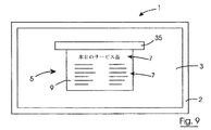
はじめに図1−10を参照すると、フレーム2及びフレーム2の窓ガラス3を含む、参照番号1で全体を示した本発明による窓がある。画像表示パネル5を窓ガラス3に貼り合わせる、即ち積層させることによる本発明による実施態様では、参照番号5で全体を示した情報を表示するための本発明による画像表示パネルを窓1に固定する。本発明によるこの実施態様では、ショーウィンドーの展示物、例えば品物や店で提供し得るその他の製品が見えるような比較的広いショーウィンドーである。画像表示パネル(visual display panel)5は、行及び列からなるマトリックス(matrix)で構成された複数の2状態(bi-state)画素8を規定する、電気−光学型パネルであり、これらは、交互かつ選択的に、第1の状態及び第2の状態で操作可能であり、第1の状態は光を透過しこれによってショーウィンドーに陳列された品物が画像表示パネル5を通して見ることが可能となり、第2の状態は本発明のこの実施態様では光を散乱或いは分散する状態であり、画像表示パネル5に情報の表示を可能にする。図9を参照されたいが、画素8の適切なものを選択し、表示すべき情報の文字や数字を形成しテキスト7を形成するために第2の状態で動作させることによって、情報を画像表示パネル5に表示する。典型的には、情報はテキスト7のスクリーンに表示され、このスクリーンは次々に連続的に表示される。
【0038】
画像表示パネル5は、内部保護パネル9及び外部保護パネル10を含み、双方とも典型的には画像表示パネル5を保護し強化するための透明なアクリル素材の透明な半硬質(semi-rigid)プラスチック素材でできている。双方とも透明なPET素材の内部基板11と外部基板12とは、それぞれの内部保護パネル9と外部保護パネル10との間に置かれる。内部基板11と外部基板12とは、これらの間に電気−光学媒体をはさみ、この実施態様では媒体はコレステリック液晶15である。保護パネル9、10、基板11、12に関する記号表示は、窓ガラス3に関連した各パネルの位置の表示である。外部保護パネル10は、窓3に最も近いものである。
【0039】
液晶媒体15の画素8は、スイッチを入れたとき、換言すれば画素8を通して電圧を印加することによってアドレスしたときに第1の光透過状態で動作し、電気の供給を切ったとき、換言すれば画素を通る印加電圧をゼロボルトにしているときは第2の散乱状態で動作する。
【0040】
透明な紫外線フィルター、この実施態様では紫外線フィルムフィルター16であるが、これは、紫外線光をフィルタリングし液晶媒体15を保護するために、外部保護パネル10と外部基板12との間に配置される。内部基板11、外部基板12、液晶媒体15、及びフィルムフィルター16と同様に内部保護パネル9、外部保護パネル10は、共に貼り合わされており、共に保持されシール17によってそれらの外周をシールされている。
【0041】
内部及び外部の基板11、12は、画素8を規定しアドレス即ち位置を決めるために、液晶媒体15と協働で動作するため、それぞれ、各行と列の電極18、19でパターン形成、即ちパターン化されている。行電極18は内部基板11でパターン化されており、一方、列電極19は外部基板12でパターン化されている。内部基板11上の行電極18は、行電極パターン化領域20を規定し、一方、外部基板12上でパターン化された列電極19は、列電極パターン化領域21を規定する。内部及び外部の基板11、12上のそれぞれの行及び列電極パターン化領域20、21は同じサイズ、形状、面積であり、よって、1つをもう1つに重ね合わせる場合は、内部及び外部基板11、12の行及び列電極パターン化領域20、21のそれぞれは、液晶媒体15が配置される範囲内にある共通のパターン化領域22を規定する。液晶媒体15によって共通パターン化領域22が構成されることを回避するために(即ち、液晶媒体15が共通パターン化領域22を越えて延在する場合には構成されてしまう)、液晶媒体15を共通パターン化領域22の範囲内に配置すべきことが重要である。それぞれの行及び列の電極18、19によって規定された画素は電気の供給を切ると光を散乱する第2の状態で動作し、光を透過する第1の状態で動作させるために電力を供給する必要があるため、液晶媒体15の一部が共通パターン化領域22を越える場合は、その部分は永続的に電力の供給を切った状態となり、従って、共通パターン化領域22を構成するする役割を果たし、光がそれを透過するのを遮る役割を果たす。
【0042】
内部基板11によって形成されたトラック支持(track carrying)側面部24は、外部基板12の行電極パターン化領域20のどちらかの側で導電トラック25のために行電極18から接続手段まで、即ち、側面部24の上縁27に沿ってコネクターブロック26に延在する。行電極18の半分は、その上にあるトラック25によって側面部24の1つの上にあるコネクターブロック26の1つに接続され、一方、行電極18のもう一方の半分は、当該側面部24のトラック25によってもう1つの側面部24上のコネクターブロック26に接続されている。外部基板12の上部トラック支持部28は、接続手段、即ち、上部トラック支持部28の上縁31に沿って置かれたコネクターブロック30で末端をなす(terminated)即ちそこに接続するような、導電トラック29のために列電極パターン化領域21を越えて上方に延在する。それぞれのコネクターブロック26、30は、ヒートシールコネクターと一般に呼ばれるタイプのものであり、選択的に画素8をアドレスするために行及び列電極18、19を電子回路37(後で詳細に説明する)に接続するためのものである。
【0043】
行及び列電極18、19、並びに、導電トラック25、29は、液晶媒体15に隣接するそれぞれの内部基板11及び外部基板12の内面32及び外面33上でパターン化されている。トラック25、29と同様に行及び列電極18、19は、インジウムスズ酸化物の被膜でパターン化されており、これは、それぞれの内部基板11及び外部基板12の内面32及び外面33のそれぞれの上でパターン化されており、適切にパターン化されエッチングされている。このインジウムスズ酸化物被膜は、画像表示パネル5の背後に置かれたショーウィンドウにある品物やその他のもののが見えなくならないように透明にする。
【0044】
プラスチック材料でできた筐体35は、画像表示パネル5の上縁36に沿って配置され、それぞれの内部基板11と外部基板12との上縁27、31は筐体35の中まで延在している。コネクターブロック26、30は筐体35のなかに配置される。電気・電子制御回路37は、筐体35のなかに配置され、
情報、及び/または、キャラクターを画像表示パネル5に表示するための行及び列電極18,19によって画素8をアドレスするため、それぞれのコネクターブロック26、30に接続されている。制御回路37は、ドライバ回路38に置かれた複数のドライバー(図示せず)、マイクロコントローラ(プロセッサ)40のもとでドライバ回路のドライバーを制御し操作する制御回路39を含む。電源回路41を含み、バッテリパック(図示せず)含む電源は、回路37及び画像表示パネル5に電力を供給するために筐体35内に配置される。マイクロコントローラ40は、適切なソフトウェアの制御のもと、テキスト7を表示するため画素8を選択的にアドレスするように動作させ、マイクロコントローラにRS323−I/Oポート42を設けてマイクロコントローラ40と通信を行うことの円滑化を図り、これによってマイクロコントローラ40をプログラムし表示すべき情報の更新や変更をし、情報のテキスト7の画面を画像表示パネル5に表示すべき順番を選択する。
【0045】
マイクロコントローラ40のプログラミング及び再プログラミング、及び、表示すべき情報の更新は、マイクロコントローラ40に提示するべき情報に関するデータをダウンロードするためのI/Oポート42に接続されているPC43の制御の下で実行される。キーボード44及び画像表示ユニット45は、マイクロコントローラ40をプログラム及び再プログラムし、かつ、情報を更新するためPC43と接続されている。I/Oポート42が筐体35内に配置されているという事実から、PC43は、窓1から画像表示パネル5を取り外す必要がなく、筐体35内のマイクロコントローラ40に容易に接続させることができる。
【0046】
行及び列電極18,19による液晶媒体15内の画素8のアドレッシング(即ち位置指定)は当業者には周知のことであり、画像表示パネル5のこの点に対してはさらに詳細を述べることを意図するものではない。また、画素8をアドレッシングするための駆動回路38のドライバーを制御するPC43によるマイクロコントローラ40のプログラミングも同様に当業者には周知であり理解されていることであり、画像表示パネル5のこの点に対してもさらに詳細を述べることを意図するものではない。
【0047】
内部保護パネル9は、適切な透明光学接着剤、典型的には、商標REXACONで市販されている接着剤、タイプOCAV光学PSA伝達フィルムによって、内部基板11に貼り合わされ、固着されている。紫外線フィルムフィルター16は、同様の透明光学接着剤によって外部基板12と外部保護パネル10とに貼り合わされ固着されている。画像表示パネル5は、同様の透明光学接着剤によって窓ガラス3に貼り合わされ固着された外部保護パネル10によって、窓ガラス3に貼り合わされている、即ち積層されている。一方、内部及び外部基板11,12は、液晶媒体15に固着されておらず、これらは、周辺シール17の働きによって、液晶媒体15に積層されたたまま保持されている。
【0048】
使用中は、情報のテキストの画面は、画像表示パネル5に選択的に表示される。このような情報の画面は、店で利用可能なものやサービスのリスト、これらのものなどの各値段、その店で得ることができる特別奉仕品、その店で得ることができる品物、及び/または、サービスの広告などを含むことができる。情報の画面は順番に表示され、情報を表示するための各画面の時間間隔は、画面ごとに変えることができ、情報を表示する画面の順序も選択可能である。情報の画面は、各画面の表示の間に小休止を入れることなく相次いで順番に表示させることもできるが、或いは、一部のもの、或いは全ての画面の間に小休止を入れることもできる。小休止の間隔は変化させることができる。表示すべき情報の画面、表示の順序、各画面の表示の継続時間、小休止の継続時間、或いは、情報の各画面の表示の継続時間は、マイクロコントローラ40のプログラミング、或いは再プログラミング、及びPC43による情報の更新のなかで全て選択されている。さらに、画面上の情報の全て或いは一部は、変化する状態のものとすることもできる。画面の情報は、上から下に、或いは、左から右にスクロールさせることができ、画面の全て或いは一部を占めさせることもできる。スクロールの一時停止の継続時間、スクロール増分の画素数は、プログラミングのなかで全て選択される。画面の追加情報は、点滅させることを選択することもできる。
【0049】
しかしながら、画像表示パネル5を窓ガラス3に固定する前に、画像表示パネル5及び制御回路37の制御のためのソフトウェアは、はじめに、PC43からI/Oポート42を通じてダウンロードされマイクロコントローラ4に入れられる。このような制御ソフトウェアは、当業者には周知である。画像表示パネル5を窓ガラス3に固定する前に、情報の画面、それらの表示の順序、情報の各画面の表示継続時間、画面の表示の間に小休止を入れるか否かが既知である場合は、画像表示パネル5を窓ガラス3に積層する前にマイクロコントローラ40は、情報の画面、それらの表示の順序、情報の各画面の表示継続時間、画面の表示の間に小休止を入れることをプログラムしておくことができる。実際の情報の画面は、PC43で初めに用意しておき、その後、I/Oポート42を通じてマイクロコントローラ40にダウンロードする。
【0050】
その後、画像表示パネル5は、動作可能の状態になり、外部保護パネル10を窓ガラス3に透明光学接着剤で接着することによって窓に積層される。
【0051】
電源回路41によって電気の供給を受けると、画像表示パネルはプログラムされた順序で情報の画面の表示を開始し、各画面はそれぞれの順序で選択された継続時間の間にわたり表示される。選択された小休止も情報の画面の間に挿入される。情報の画面の全て、或いは一部を変更することを所望する場合は、これはI/Oポート42を通じたPC43によるマイクロコントローラ40の再プログラミングによって実行される。また、全ての、或いは一部の情報画面の表示の持続時間、或いは、情報画面の順序を変更することを所望する場合は、同様にこれはI/Oポート42を通じたPC43によるマイクロコントローラ40の再プログラミングによって実行される。PC43によるマイクロコントローラ40の再プログラミングは、画像表示パネル5を窓ガラスから取り外す必要なしに、適切なケーブルコネクターでPC43を単に接続するだけで、実行することができる。
【0052】
マイクロコントローラ40がそれぞれの情報画面の間に小休止を入れるようにプログラミングされている場合は、各小休止の間は、画像表示パネル5の全ての画素8は第1の光透過状態で操作され、その結果、店のウィンドウに陳列されている全ての商品(article)及びその他の品物に対して明瞭かつ遮るもののない視界を可能にする。
【0053】
画像表示パネル5は情報画面を表示するために動作するとき、表示されることとなる情報の文字、数字、或いはキャラクターを形成するため第2の光散乱状態で操作される画素8のみが、店のウィンドウにあるディスプレイの商品やその他の品物が見られることを妨害する。しかしながら、情報画面の背景を形成する画素8は、第1の光伝達(透過)状態で動作し、店のウィンドウの商品やその他の品物の視認性の悪化は最小化される。
【0054】
本発明のこの実施態様による本発明の利点は数多くある。本発明の特に重要な利点は、画像表示パネル5が、画像表示パネル5を通した視界を顕著に悪化させることなく、情報の表示を可能にすることである。実際には、僅かに視界を悪化させ得るような画像表示パネル5の唯一の部分は、筐体26の部品だけである。しかしながら、本発明のその他の実施態様を参照しながら後述するように、筐体を設けずに、画像表示パネルを通した店のウィンドウの商品やその他のものに対する視界即ち視認性が阻害されることを完全に回避するようにすることもできる。しかしながら、画像表示パネルの上端に沿って延在する筐体を提供することによって、たいていの場合、ウィンドウの商品や品物の視界を妨害することのないように、筐体を窓に相対した高さで窓ガラスに配置することができる。本発明のさらなる利点は、画像表示パネル全体が透明であるため、メッセージが表示されるまで目立たず、そして、気付かれないものであり、よって、これはショーウィンドウにあるものを見る人々の目を引きつけるような驚きの要素となる。
【0055】
本発明のこの実施態様のさらなる利点は、列電極19が形成されている外部基板12が、共通のパターン化領域22の側面の境界に沿った各側面のエッジで終了させることができる。さらに、行電極18がパターン化されている内部基板11は、共通のパターン化領域22の下端に一致するその下端に沿って終了させることができる。このことは、共通のパターン化領域22内に液晶媒体15を配置することをさらに容易にする。
【0056】
図11−15を参照すると、窓1と同様であり、同様の要素は同じ符号で示した、全体を符号50で示した本発明のその他の実施態様による窓を図示してある。本発明のこの実施態様では、全体を符号51で示した本発明による画像表示パネルも、窓1の窓ガラス3に固定された画像表示パネル5のように、積層することによって窓50の窓ガラス3に固定されている。画像表示パネル51は、画像表示パネル5と実質的に同じであり、同様の要素は同じ参照番号で識別する。
【0057】
しかしながら、本発明のこの実施態様では、内部基板11の行電極パターン化(パターン形成されている)領域20から延在するトラック支持サイド部24は、それぞれのサイドエッジ53に沿ったブロックコネクター26で末端をなす導電トラック25を具える。本発明のこの実施態様では、内部基板11の各行電極18は、それぞれのサイド部24上のトラック25を通して、図1−10の画像表示パネル5の制御回路37と同様の制御回路(図示せず)によってアドレスされる。これの利点は、電極18がその端部のすぐにそばで切断された場合に、電極18の半分が双方とものアドレスが続行されることである。上部トラック支持部28は、外部基板12の列電極パターン化領域21から延在しており、下部トラック支持部54は、本発明によるこの実施態様では、それぞれの上部トラック支持部28と下部トラック支持部54のサイドエッジ55に沿って配置されているようなコネクターブロック30に連絡している列電極19から導電トラック29を支持するために、外部基板12の列電極パターン化領域21から下方に延在している。外部基板12上の列電極19の半分は、外部基板12の上部28上のトラック29によってアドレスされるが、一方、外部基板12の列電極19のもう半分は、外部基板12の下部54上のトラック29によってアドレスされる。コネクターブロック26、30は、画像表示パネル5に関して説明したものと同様であり、図1−10の画像表示パネル5を参照して既に説明した制御回路37と同様の制御回路(図示せず)に接続するために同様に設けるものである。
【0058】
それぞれの筐体57は、制御回路(図示せず)と同様にコネクターブロック26、30、及び、内部基板11、外部基板12のサイドエッジ部53、55のそれぞれを収容するために、画像表示パネル51のそれぞれのサイドエッジ部58に置かれる。各筐体57に配置することができる制御回路(図示せず)のそれぞれの部分の間の通信を容易にするため、さらなる導電接続トラックを、外部基板12の上部トラック支持部28及び下部トラック支持部54上に提供することもできる。
【0059】
或いは、画像表示パネル51は、画像表示パネル5と同様であり、説明してなかったが、紫外線フィルムフィルターと同様に内部保護パネル9、外部略パネル10を含む。液晶媒体15は、画像表示パネル5のそれと同様であり、即ち、コレステリック液晶媒体であり、よって、画素8は、電力を供給されたときに光を透過する第1の状態で動作する。電力の供給を切ったときに光を散乱する第2の状態で動作する。本発明のこの実施態様では、液晶媒体15が、それぞれの内部基板11及び外部基板12の共通のパターン化領域22を越えて延在しないことを保証するように配慮がなされている。実際、内部基板11は、共通のパターン化領域22を越えて延在する液晶媒体15の障害を最小化するために、共通のパターン化領域22の上端及び下端に一致させた、その上端と下端とで末端をなす。
【0060】
画像表示パネル51の使用は画像表示パネル5のそれと同様である。画像表示パネル51は、適切な透明光学接着剤によって外部保護パネル(図示せず)を窓ガラス3に接着することによって窓ガラス3を積層させてあり、所望の継続時間で所望の順序で各画面の表示の間の小休止の有無を定義した情報画面の表示のプログラミング及び再プログラミングは、画像表示パネル5を参照して既に説明したものと同様である。
【0061】
図16−18を参照すると、本発明の他の実施態様による、全体を符号60で示した窓60が図示されており、これにはいショウウィンドーなどの窓60の窓ガラス3に積層によって固定された画像表示パネル69を含む。画像表示パネル69は、図1−10を参照して説明した画像表示パネル5と実質的に同様であり、同様の要素は同じ参照番号で識別される。本発明のこの実施態様では、画像表示パネル69は、窓ガラス3の大部分を覆うように延在し、別個の筐体に配置する代わりに電子制御回路(図示せず)が、窓60の窓フレーム2に収容されている。窓フレーム2は、制御回路(図示せず)を収容するために中空であり、説明の便宜上図16では破線で示してある。電子制御回路(図示せず)は、図1−10の画像表示パネル5のそれと同様であり、その操作も同様である。画像表示パネル69のマイクロコントローラのプログラミング及び再プログラミングを容易にするためI/Oポート(図示せず)を制御回路(図示せず)のマイクロコントローラに接続された窓フレーム2に設ける。
【0062】
内部基板11のサイド部24は、列電極パターン化領域20のそれぞれの反対の側に延在しており、列電極18から接続しているコネクターブロック26まで、導電トラック25を支持(carring)するために窓60のフレーム2に延在するようなそれぞれのサイドエッジ部61で末端をなす。外部基板12の上部トラック支持部28及び下部トラック支持部62は、それぞれ、列パターン化領域21から上方及び下方に延在しており、上端63及び下端64で末端をなし、列電極19をアドレスするため導電トラック29及びコネクターブロック30を支持するためにフレーム内に延在する。
【0063】
本発明のこの実施態様では、液晶媒体15は、画像表示パネル5と同様にコレステリック液晶媒体であり、図示してないが、紫外線フィルムフィルターと同様に内部保護パネル及び外部保護パネル9、10も設けてある。内部及び外部保護パネル9、10は、相互に重なりあうときにそれぞれの内部及び外部基板11、12の形状に合う十字の型にすることができ、或いは、窓ガラス3のそれと同様の面積にすることもできる。実際、本発明のこの実施態様、及び既に説明した或いはこれから説明するであろうその他の実施態様では、外部基板12及び内部基板11の何らかの露出した領域を積層しガラス窓に直接接着しそれが外部保護パネルの機能を果たすようなケースでは、特定の外部保護パネル10の設備は省略し得ることを想定している。紫外線フィルムフィルターは、液晶媒体を保護するために液晶媒体15と実質的に同じ面積にする必要がある。従って、外部保護パネルを設けない場合は、紫外線フィルムフィルターはガラス窓3と外部基板12との間に積層し直接接着させる。
【0064】
液晶媒体15が共通のパターン化領域22を越えて延在しないことを保証する配慮がなされている。内部基板11は、それぞれ列電極パターン化領域20に一致するような、上端65、下端66に沿って末端をなすが、一方、外部基板12は、共通のパターン化領域22を越えて延在する液晶媒体15の障害を最小化するため、列電極パターン化領域21に一致するそれぞれのサイドエッジ67、68に沿って末端をなす。
【0065】
さらに、本発明のこの実施態様では、列電極19を半分にして2つ設ける、即ち、上半分19aと下半分19bとである。列電極19の上半分19aは、外部基板12の上部トラック支持部28上の導電トラック29によってアドレスされ、一方、電極19の下半分19bは、外部基板12の下部トラック支持部62上の導電トラック29を通じてアドレスされる。
【0066】
その他の点では、画像表示パネル60及びその使用は、既に述べた画像表示パネル5のそれと同様である。
【0067】
図19、12を参照すると、符号70で全体を示した本発明のその他の実施態様による窓が示してある。略図のみで図示した画像表示パネル71は、間隔をあけて窓1の窓ガラス3に固定されている。画像表示パネル71は、画像表示パネル5と実質的に同様であり、同様の要素は同じ参照番号で識別する。本発明のこの実施態様では、画像表示パネル71の電子制御回路(図示せず)を収容するため、画像表示パネル71の上部及び下部に一対の筐体35を設ける。電子制御回路(図示せず)は、画像表示パネル5のそれと同様であり、その動作も同様である。本発明のこの実施態様では、それぞれの筐体35の上部、下部に装着された吸盤72によって窓ガラス3に固定されている。別の点では、画像表示パネル71は画像表示パネル5と同様であり、その使用も画像表示パネル5のそれと同様である。
【0068】
図21、22を参照すると、窓1と同様であり同様の要素は同じ参照番号で識別されるようなかたちで、本発明による窓80が示してある。本発明による画像表示パネル81は窓80に装着されている。画像表示パネル81は、画像表示パネル5と実質的に同様であり、同様の要素即ち構成部品は同じ参照番号で識別されている。しかしながら、画像表示パネル81は、略式でのみ図示してある、本発明のこの実施態様では、筐体35の上部及び下部の組は、画像表示パネル81の上部及び下部に配置され、窓1のフレーム2の上部及び下部のサッシ83の間に延在する透明な連結線、典型的にはナイロン(登録商標)線82、及び、筐体35は、窓80の画像表示パネル8を吊るす。別の点では、画像表示パネル81及びその使用及び操作は、図1−10を参照しながら既に説明した画像表示パネル5と実質的に同様である。
【0069】
図23を参照すると、全体を符号90で示した、本発明の他の実施態様による窓の横断面図が示されている。本発明のこの実施態様の窓90は、それらの間に空洞93を規定するような相互に離間された、ガラスでできた外部平板91及びガラスでできた内部平板92を持つ二重ガラス(double glazed)の窓である。平板91、92は、中空のフレーム94内に延在し固定される。図16−18を参照して説明した画像表示パネル60と同様のものである画像表示パネル95は空洞93内に配置されるが、しかしながら、本発明のこの実施態様では、内部保護パネル9は、適切な透明光学接着剤で接着させることによって窓90の内部平板(即ち内部窓ガラス)92に積層されている。内部及び外部基板11、12のサイドエッジ61、63、64は、フレーム94のなかに延在している。内部基板11のトラック支持サイド部24のサイドエッジ61は、フレーム94の側面部材96内に延在している。外部基板12の上部トラック支持部28及び下部トラック支持部62の上部エッジ63、下部エッジ64は、それぞれ、フレーム94の上部部材及び下部部材のなかに延在している。フレーム94の下部部材97のみが示されている。
【0070】
従って、それぞれのトラック支持部24、28、62上に保持されるコネクターブロック26、30は、フレーム94内に配置される。電子制御回路37は、画像表示パネル95を制御し操作するためにフレーム94内に配置される。制御回路37は、ケーブルでコネクターブロック26、30に接続されているが、しかしながら、図23ではコネクターブロック30が見えないため、制御回路37のみの接続がケーブル98でコネクターブロック26に接続するかたちで図示されている。しかし、ケーブル98によるコネクターブロック30の制御回路37に対する接続は当業者には容易に理解されるであろう。制御回路37のマイクロコントローラ(図示せず)は、フレーム94に配置されたI/Oポート(図示せず)を通じてプログラム可能、及び再プログラム可能である。外部保護パネル10は、外部平板91から離されており、窓90内の断熱空洞の存在を保証する。
【0071】
その他の点では、画像表示パネル95、その使用及び操作は、図1−10を参照して既に説明した画像表示パネル5と同様である。
【0072】
或いは、窓のフレーム内に電気及び電子の制御回路37を配置する代わりに、制御回路37をガラスの平板の間の空洞に配置することを可能にする目立たない部品で実現させることを想定している。典型的には、制御回路37がガラスの平板の間にある空洞に配置される場合は、制御回路は、窓のフレームによって少なくとも部分的に画された周辺端部、即ち窓の端部に向かって配置されるが、この電子回路の構成要素が十分に目立たないものであるならば、このような構成要素は窓の脇の通行人の視界を遮蔽しない程度のサイズであり視界は遮蔽されない。
【0073】
一般的に画像表示パネルが、コレステリック液晶媒体で提供される電気−光学媒体を含むものとして説明してきたが、その他の何らかの適切な電気−光学媒体を使用することもできる。しかしながら、その透明状態において媒体が比較的広い視角、好適には視角180°全部にわたって透明な状態を保持するような電気−光学媒体を選択することが重要である。さらに電気−光学媒体は、透明状態でその視角全体にわたって曇り(haze)がないものとすべきである。光を遮る、即ち散乱させる状態では、電気−光学媒体は鏡面反射光(specular light)を散乱することが好適であり、この理由から好適な電気−光学媒体はコレステリック液晶媒体である。しかしながら、電気−光学媒体は、光を遮る状態、或いは、浮遊粒子ディスプレイ(suspended particle display)などのように光を吸収する状態でも同様に動作することができることが容易に理解される。或いは、電気−光学媒体は、有機発行ダイオードディスプレイのように光を発するタイプにすることもできる。エレクトロクロミック媒体を電気−光学媒体として使用することもでき、ポリマー分散液晶媒体として使用され得る。電気−光学媒体は、画素が第2の状態で動作する場合に、第2の状態で動作している画素上に入射する光のうちのある比率の光が後方散乱するような媒体とすることもできる。あるコレステリック液晶媒体は、後方散乱モードで動作するのに特に適している。第2の状態で動作している画素は、典型的には入射光の15%と70%との間で後方散乱する。理想的には入射光の50%の後方散乱比が所望される。実際には、入射光の30%の後方散乱比が達成可能である。第2の状態で動作する画素からの光の後方散乱は、の後方散乱の効果が、第2の状態で動作する画素と第1の状態で動作する画素との間のコントラストを増大させる場合に、特に重要な利点となる。従って、表示されているテキスト、及び/または、その他のキャラクターは、よりシャープに表現される。
【0074】
画素は、電気を供給されたときに光を透過する状態にあるものとして説明してきたことが理解されるが、電気−光学媒体は、画素への電気の供給を切ったときに光を透過する状態で動作するようなものを選択することもできる。言うまでもなく、キャラクター即ち情報を表示させるために、光散乱状態で動作させる代わりに、画素が光を分散する、光を遮る、光を反射する、或いは光を出射する状態で動作するような電気−光学媒体を選択することもできる。
【0075】
画素は双安定画素(bi-stable pixels)にする必要はなく、2状態画素(bi-state)とする必要だけはある。各画素をスイッチするトランジスタなどの能動素子(active element)を必要とするアクティブマトリックス技法と反対のパッシブマトリックス技法によって画素がアドレス可能であれば十分である。コレステリック液晶媒体ディスプレイは、双安定(bi-stable)であり、それゆえにその画素も同様に双安定画素である。
【0076】
本発明による画像ディスプレイは、ダイナミック方式で情報を表示するよう動作させることができ、これによってショーウィンドウの前の通行人の興味を惹き付けることができる。チェーンストアに、即ち、同時に複数のチェーンストアのある支店グループに配置された複数の画像表示パネルに表示される情報を変更するため、画像表示パネルの電子制御回路のマイクロコントローラは、インターネットを越えて、或いは、携帯電話のショートメッセージサービスを介して遠隔地からプログラムしたり再プリグラムしたりすることができる。実際には、チェーンストアの店のショーウィンドウにある、或いは、銀行、その他の会社や期間の支店の窓にある複数の画像表示パネルがインターネットやその他のネットワークシステムを介してネットワークを形成することができ、表示されている情報画面は、ネットワークを介して同時に制御し更新することができ、その結果、同じ情報画面が会社や機関の全ての窓に同時に表示されること、を想定している。
【0077】
制御回路のマイクロコントローラを適切に操作、或いはプログラムらミングすることによって、情報即ちデータを容易かつ選択的に変更することができることはもちろんであることを理解されたい。実際に、あるケースでは、ある一定の時間、情報が何も表示されず、画像表示パネルの全ての画素が光透過状態で動作することも想定される。
【0078】
画素を反対に動作させる、換言すれば、光透過状態でキャラクター即ち情報を形成する画素を操作し、残りの画素が、光を分散、散乱、反射、或いは遮蔽する状態にすることによってキャラクター、即ち情報を表示することができることも想定される。
【0079】
全ての場合の窓は、窓にはめ込まれた画像表示パネルを持つものとして説明してきたが、ある場合には、画像表示パネルが窓を形成することを想定している。このような場合には、画像表示パネルの外部保護パネルが窓ガラスとして効果的に機能し、ガラス、或いはその他の適切な素材を用いることができる。
【0080】
図16−18を参照した本発明の実施態様では、それらの対向する各端部からアドレス可能な分割電極(split electrode)として列電極を説明してきたが、行電極も分割電極として設けることができ、このような分割電極は同様にそれらの対向する各端部からアドレス可能なものとなることも想定している。さらに、当業者には容易に理解し得ることであるが、本発明のその他の実施態様を参照して開示した画像表示パネルの行及び列電極も同様に、それらの対向する各端部からアドレス可能な分割電極として設けることができる。
【0081】
図16−18を参照した本発明の実施態様では、制御回路は窓の窓フレーム内に配置するものとして説明してきたが、制御回路は窓フレーム(枠)の外に配置することもできる。図23を参照して説明した2重窓のケースでは、制御回路を窓フレームの外部に設置することができることを想定している。
【0082】
図23を参照して説明した窓は、図16−18を参照して説明したものと同様の画像表示パネルを含むものとして説明してきたが、図23を参照して説明した窓は、その他の図を参照して説明した窓の一部を形成するようなその他の画像表示パネルのいずれかとして提供することもできる。実際には、特に、図1−10を参照して説明した窓の画像表示パネルを図23の窓に組み合わせて使用することを想定している。このような場合には、それぞれが内部基板11、外部基板12上に配置された、コネクターブロック26、30に沿った上端27、31は、図23の窓の上部の周辺の端部に隣接して末端をなす。
【0083】
様々な画像表示ディスプレイパネルを持つ窓は、窓に固定されたままでプログラム可能、再プログラム可能なものとしての画像表示パネルの制御装置と共に説明してきたが、画像表示パネルを窓に固定する前に制御回路の最初のプログラミングが実行されることは当業者には即座に自明なことであろう。或いは、初期プログラミングは、画像表示パネルが実際に窓に固定されているときに実行することも同様にできる。画像表示パネルの制御回路のプログラミングや再プログラミングは、何らかの適切な通信手段やプロトコルによって実行することができる。例えば、窓ガラスに固定されているときは、画像表示パネルの制御回路は、何らかの適切なネットワーク、例えば、無線ネットワーク、赤外線、ブルートゥース、或いは、このディスプレイと通信するようなGSMモジュールの使用によって、プログラムや再プログラムをすることができる。
【0084】
特定の素材からなるものとして保護パネルを説明してきたが、保護パネルはその他の適切な材料からなるものとして設けることができる。実際には、多くの場合、保護パネルを省略することができ、上述したように画像表示パネルが2重窓ユニットの空洞内に配置される場合は、保護パネルを完全に省略することができる。さらに、窓ガラスがその他の保護パネルとして機能するため、多くの場合、保護パネルを1つだけ必要とする。言うまでもなく、上述したようにある場合には全く保護パネルを設けないこともできる。
【0085】
キャラクターは、国際的な言語であるUnicodeキャラクターセットの形式で提供することができることを想定している。画像表示パネル上に表示される情報の画面は、ベクトル形式或いはビットマップ形式でグラフィック情報を含ませることもできる。このような形式の情報画面は当業者には周知のことである。
【0086】
本発明のさらなる利点は、第1の状態で動作する画素が光透過状態で動作するときに、画像表示パネルが第1の状態で動作する画素を含む領域が透明になるという事実の効力によるものである。従って、このパネルは両側から見ることができる。これは、適切にこのパネルをプログラミングすることによって、例えば画像表示パネルに表示されることとなるテキストなどの情報を画像表示パネルのどちらの側からも読み取ることができることを可能にする。画像表示パネル上の情報を1つの側、例えば、窓の外側から見られるように表示することを所望する場合は、パネルが窓の外から観察されるときにテキストを左から右に読み取られるように表示する。他方、情報を窓の中から読み取らせることを所望する場合は、パネルが窓の中から観察されるときに、情報のテキストを左から右に読み取られるように表示する。これは、テキスト及び/またはその他のキャラクターを表示するための第2の状態で操作されるべき画素を適切にアドレスすることによって達成される。
【図面の簡単な説明】
【0087】
【図1】本発明による窓の正面図である。
【図2】図1のII-II線の図1の窓の横断面立面図である。
【図3】ある部分を除いた図1の正面図である。
【図4】図1の窓の一部の拡大正面図である。
【図5】図1の窓の細部を示す横断面図である。
【図6】図1窓の一部の正面図である。
【図7】図1の窓のその他の部分の正面図である。
【図8】図1の窓の電子回路を示すブロック図である。
【図9】表示に使用した図1の窓の正面図である。
【図10】プログラムし図8の電子回路を示すブロック図である。
【図11】本発明のその他の実施態様による窓の正面図である。
【図12】図11のXII−XII線の図11の窓の横断面立面図である。
【図13】図11の窓の一部の正面図である。
【図14】図11の窓の細部を示す正面図である。
【図15】図11の窓のその他の細部を示す正面図である。
【図16】本発明のその他の実施態様による窓の正面図である。
【図17】図16の窓の一部の正面図である。
【図18】図16の窓のその他の一部の正面図である。
【図19】本発明のその他の実施態様による窓の正面図である。
【図20】図19のXX−XX線の図19の窓の横断面立面図である。
【図21】本発明のさらにその他の実施態様による窓の正面図である。
【図22】図21のXXII−XXII線の図21の窓の横断面立面図である。
【図23】本発明のさらにその他の実施態様による窓の断面平面図である。【Technical field】
[0001]
The present invention relates to a method for displaying windows and characters, particularly for displaying information in windows, and to an image display panel.
[Background Art]
[0002]
It is desirable to display information in windows, and sometimes in store or bank windows, for example, such information can be obtained from a list of available services and goods from the store owner and their current May be included. Such information may also include information about special offers (services) on a particular day, or a particular week, or other period. Because such special offers are changed frequently, daily, weekly, and hourly, the windows that inform the public of special offers and other information should be easily and readily changeable. is there. Generally, the only satisfactory way to display such information is a poster, a poster affixed to the inside of a show window glass window. Such posters have a number of drawbacks, especially when the poster is placed in the area of greatest interest on the window glass of a shop window (ie, the shop window). It will be placed all the time in a window area that blocks the eyes of the public on the product. This is not preferred. A further disadvantage of posters is that each time the information displayed on the poster is updated or changed, the existing poster must be replaced with a new poster. This is a very difficult task, especially if the display area of the shop window is a relatively limited area and / or if it is used to fully display the goods. It is. This is a very serious problem if the special service offers and information presented on the posters are updated and changed frequently.
[0003]
Therefore, there is a need for a window that can display characters and / or information that overcomes the aforementioned problems. There is also a need for a way to display characters and / or information.
[0004]
It is an object of the present invention to provide such windows and methods, and also to provide a visual display panel.
[0005]
According to the invention, the image display panel is fixed to a window, the image display panel comprises a plurality of individually addressable pixels arranged in a matrix of rows and columns, said pixels being alternately and selectively at least Operable in two states, the states including a first state in which light is transmitted through the image display panel and a second state in which light is scattered, dispersed, reflected, or blocked. Selecting at least one character on the image display panel by forming at least one of the pixels in the second state and forming a character to be displayed. There is provided a window, including a window glass, which can be displayed visually and provides visual access through the image display panel by the pixel in the first state.
[0006]
In one embodiment of the present invention, the area of the image display panel is substantially the same as the area of the window glass. Alternatively, the area of the image display panel is smaller than the area of the window glass.
[0007]
In another embodiment of the present invention, the window glass forms a part of the image display panel. Alternatively, the image display panel forms a part of the window glass.
[0008]
Preferably, the image display panel is placed substantially parallel to the window glass. It is advantageous that the image display panel is attached to the window glass, that is, laminated.
[0009]
In one embodiment of the present invention, the window glass is a window glass including a window having a single structure (single glaze construction). It is preferable that the image display panel is fixed to an inner surface of a window glass including a window having a single structure. Alternatively, the glass window is a window glass having a double structure, and preferably, the image display panel is provided between an inner surface and an outer surface of the window having a double structure (double glaze construction). In the cavity specified in. Further, it is preferable that the image display panel is fixed to an inner surface of the window having a double structure.
[0010]
In one embodiment of the present invention, the image display panel includes an electro-optical medium. It is advantageous that the image display panel includes a pair of panel substrates made of a transparent material, and the electro-optical medium is disposed between the panel substrates. One of the panel substrates is patterned with a plurality of row electrodes, and the other of the panel substrate is patterned with a plurality of column electrodes, so that each of the row and column electrodes defines the pixel. It is preferred that they operate in cooperation with each other. Ideally, the row and column electrodes are made of a transparent material.
[0011]
In one embodiment of the present invention, the row and column electrodes on each of the panel substrates are patterned with a layer of indium tin oxide (ITO) formed on each of the panel substrates.
[0012]
In one embodiment of the present invention, the row and column electrodes on each of the panel substrates define a respective patterned area and operate co-operating to form the pixels. When operating simultaneously, each of the patterned regions defines a common patterned region such that each of the patterned regions is common to each of the respective patterned regions; and Are defined in the area where the pattern is formed. Preferably, the electro-optical medium is included in the common patterned area.
[0013]
In one embodiment of the invention, at least one track carrying portion extends from the patterned region of each of the substrates, and connection means extends to each of the track supports. A plurality of tracks are patterned in each of the track supports to connect the electrodes of the corresponding substrate to the corresponding connection means for addressing the electrodes through the connection means. Preferably, said connecting means of each of said track supports is arranged towards an end of said track support. Advantageously, the track support of one of the substrates extends to one side of the patterned area.
[0014]
In one embodiment of the present invention, a pair of the track supports extend from respective opposite sides of the patterned region of one of the substrates.
[0015]
Also, in one embodiment of the invention, the connecting means on the track support are arranged adjacent to each end of the track support, such as adjacent to each other.
[0016]
In one embodiment of the present invention, the track support of one of the substrates extends upward from the patterned region of the substrate.
[0017]
Also, in one embodiment of the invention, each of the track supports extends upward from one of the substrates and downward from the patterned area.
[0018]
In one embodiment of the present invention, each of the track supports extends to a peripheral edge of the window glass so that the connecting means can be arranged in a frame of the window.
[0019]
In one embodiment of the present invention, the conductive tracks on the track support are patterned with a layer of indium tin oxide formed on each of the substrates.
[0020]
In one embodiment of the present invention, the pixel applies the voltage to or removes each of the electrodes that define the pixel whose state is to be changed, so that the pixel is in the first state. Operable between the second state. Preferably, the pixel is configured to apply a voltage across the electrode defining the pixel, wherein the state of the pixel is to be changed from the second state to the first state. The state is operated from the state to the first state. The pixel is configured to de-energize, i.e., remove, the voltage across the electrode defining the pixel whose state of the pixel is to be changed from the first state to the second state. It is advantageous to operate from the first state to the second state.
[0021]
Also, in one embodiment of the present invention, to selectively operate the pixel defined by the electrode from one of the first state and the second state and vice versa, A drive circuit is provided for applying a voltage to each of the selected electrodes above.
[0022]
In another embodiment of the present invention, the drive circuit is integrated with a window frame of the window.
[0023]
In a further embodiment of the invention, a UV film filter is arranged adjacent to one of the substrates to protect the electro-optical medium from UV light.
[0024]
Preferably, at least one protection panel for protecting the image display panel is provided. It is preferable that a pair of protection panels is provided, and the substrate is disposed between each of the protection panels.
[0025]
In one embodiment of the present invention, each of the protection panels is made of a PET material. Alternatively, each of the protection panels is made of an acrylic material.
[0026]
In one embodiment of the present invention, the window glass forms one of the protection panels.
[0027]
In another embodiment of the present invention, the electro-optical medium is a liquid crystal medium. Preferably, the liquid crystal medium is a cholesteric liquid crystal. Alternatively, the electro-optical medium is a suspended particle device medium. Also, in an alternative embodiment of the present invention, the electro-optical medium is an electrochromic medium. In another embodiment of the invention, the electro-optical medium is a polymer dispersed liquid crystal medium. Also, in a further alternative embodiment of the invention, the electro-optical medium is an organic light emitting diode medium.
[0028]
In a further embodiment of the present invention, each of the pixels includes a light emitting diode operating in the second state when a voltage is applied to each of the electrodes defining the pixel, the light emitting diode Is defined.
[0029]
In one embodiment of the present invention, the pixels are bi-state pixels. Preferably, said pixels are bi-stable pixels.
[0030]
Also, in one embodiment of the present invention, the pixels are selectively addressable to form at least one character. Preferably, the pixels are selectively addressable to form a plurality of characters. Preferably, a part of the character is an alphabetic character, or a part of the character is a number. It is also advantageous that each of the pixels is selectively addressable for displaying characters and / or numbers for transmitting information.
[0031]
Also, in one embodiment of the present invention, each of the pixels when operating in the second state, i.e. when operating, backscatters a portion of the light incident on the pixel. Preferably, when each pixel is operating in the second state, it backscatters 15% to 70% of the light incident on the pixel, and ideally at least 30% of the light incident on the pixel. Backscatter. It is also desirable to backscatter about 50% of the light incident on the pixel.
[0032]
The present invention also provides a method for displaying a character on a window glass. The method includes securing an image display panel including a plurality of individually addressable pixels arranged in a matrix of rows and columns to the window, wherein the pixels alternately and selectively include at least two pixels. Operable in a state, the state including a first state for light to pass through the image display panel, and a second state in which light is scattered, dispersed, reflected, or blocked; Thus, at least one of said pixels is selectively operable in said second state and selectively forms at least one character on said image display panel by forming a character to be displayed. Being displayable and providing visual access through the image display panel by the pixel in the first state.
[0033]
The present invention further provides an image display panel. The panel includes a plurality of individually addressable pixels arranged in a matrix of rows and columns, wherein the pixels are alternately and selectively operable in at least two states, the states being light Includes a first state for transmission through the image display panel, and a second state in which light is scattered, dispersed, reflected, or blocked, so that at least one of the pixels is Forming a character to be displayed in the second state, wherein at least one character can be selectively displayed on the image display panel; The pixel provides visual access through the image display panel.
[0034]
The advantages of the present invention are numerous. In particular, characters, informational texts, and the like, can be viewed through the shop window by ordinary people who view goods, goods, and the like in the shop window, i.e., the shop window behind the image display panel. The image can be displayed on the image display panel without obstructing or obstructing the field of view. The pixels of the image display panel can be operated in a first state in which light is transmitted, and the pixels can be operated in a second state in which light is scattered, dispersed, and reflected, that is, light is blocked. By virtue of being certain, only pixels needed to form characters, characters and / or numbers are displayed in the second state in order to display information or characters. Thus, the remaining pixels are operated in a first state that is transparent to light, whereby the items or other items that are the display window display behind the panel through the pixels operating in the first state. Provides a clear view to the Accordingly, only a part of the image display panel that partially obstructs the view of an unspecified viewer passing through the window as the case may be may operate in the second state, and the character and / or numerical information, or 1 Pixels operating in a second state, such as forming one or more characters. Thus, it will be readily apparent to one of ordinary skill in the art that the viewing of items or products placed behind the image display panel is minimally obstructed.
[0035]
A further advantage of the present invention is that the image display panel can be updated quickly and easily. The reason is that by addressing the appropriate pixels, the information or character can be changed quickly and easily. This is a particularly important advantage if it is desired to display rapidly changing information. For example, when using a window with a fixed image display panel to display lottery information on a nationwide scale, for example, when displaying information on a jackpot prize relating to the lottery, the jackpot prize is purchased according to the purchase of the lottery. When the image display panel is directly connected to a computer or other device that continuously updates the jackpot prize amount, information on the jackpot prize amount can be instantaneously updated. For example, it is envisioned that the image display panel may be connected to a computer that calculates the jackpot prize amount via the Internet or some other suitable communication channel to update the jackpot prize amount instantaneously. .
[0036]
A further advantage of the present invention is achieved when the image display panel is glued directly to the window, i.e., laminated, where the entire image display panel is inconspicuous and effectively integrated into the window. If the image display panel extends over a significant portion of the window, it will have little or no hindrance to viewing the items in the window behind the image display panel. The reason is that a circuit for controlling the image display panel can be housed in the window frame of the window.
[0037]
BRIEF DESCRIPTION OF THE DRAWINGS The present invention will be readily understood from the following description, which is a preferred embodiment for illustration only, with reference to the drawings, in which
Referring initially to FIGS. 1-10, there is a window according to the present invention, generally designated by the
[0038]
The
[0039]
The pixel 8 of the liquid crystal medium 15 operates in the first light transmission state when switched on, in other words when addressed by applying a voltage through the pixel 8, and when the supply of electricity is cut off. For example, when the applied voltage through the pixel is at zero volts, it operates in the second scattering state.
[0040]
A transparent UV filter, in this embodiment a UV film filter 16, is disposed between the external protection panel 10 and the external substrate 12 to filter the UV light and protect the liquid crystal medium 15. The internal protection panel 9 and the external protection panel 10 are bonded together as well as the internal substrate 11, the external substrate 12, the liquid crystal medium 15, and the film filter 16, are held together, and the outer periphery thereof is sealed by a seal 17. .
[0041]
The inner and outer substrates 11, 12 are operated in cooperation with the liquid crystal medium 15 to define and address or position the pixels 8, so that each row and column of
[0042]
The track carrying sides 24 formed by the inner substrate 11 are provided on either side of the row electrode patterned area 20 of the outer substrate 12 for the conductive tracks 25 from the
[0043]
Row and
[0044]
A
Connected to respective connector blocks 26, 30 for addressing pixels 8 by row and
[0045]
Programming and reprogramming of the
[0046]
The addressing (or positioning) of the pixels 8 in the liquid crystal medium 15 by the row and
[0047]
The inner protection panel 9 is glued and fixed to the inner substrate 11 by a suitable transparent optical adhesive, typically an adhesive sold under the trademark REXACON, type OCAV optical PSA transmission film. The ultraviolet film filter 16 is attached and fixed to the external substrate 12 and the external protection panel 10 with the same transparent optical adhesive. The
[0048]
During use, the information text screen is selectively displayed on the
[0049]
However, before fixing the
[0050]
Thereafter, the
[0051]
When supplied with power by the
[0052]
If the
[0053]
When the
[0054]
The advantages of the invention according to this embodiment of the invention are numerous. A particularly important advantage of the present invention is that the
[0055]
A further advantage of this embodiment of the invention is that the outer substrate 12 on which the
[0056]
11-15, there is illustrated a window according to another embodiment of the present invention, generally designated 50, similar to
[0057]
However, in this embodiment of the invention, the track support side portions 24 extending from the row electrode patterned (patterned) regions 20 of the internal substrate 11 are connected by
[0058]
Each housing 57 is provided with an image display panel for accommodating each of the connector blocks 26 and 30 and the side edges 53 and 55 of the internal board 11 and the external board 12, similarly to a control circuit (not shown). 51 at each side edge 58. To facilitate communication between respective parts of a control circuit (not shown) that can be located in each housing 57, additional conductive connection tracks are provided on the upper board support 28 and the lower track support 28 of the external substrate 12. It can also be provided on the part 54.
[0059]
Alternatively, the image display panel 51 is the same as the
[0060]
The use of the image display panel 51 is the same as that of the
[0061]
Referring to FIGS. 16-18, there is shown a window 60, generally designated 60, according to another embodiment of the present invention, which is secured to the pane 3 of the window 60, such as a show window, by lamination. Image display panel 69 is provided. Image display panel 69 is substantially similar to
[0062]
Side portions 24 of the internal substrate 11 extend on opposite sides of each of the column electrode patterned regions 20 and carry conductive tracks 25 from the
[0063]
In this embodiment of the present invention, the liquid crystal medium 15 is a cholesteric liquid crystal medium similarly to the
[0064]
Care is taken to ensure that the liquid crystal medium 15 does not extend beyond the common patterned area 22. The inner substrate 11 terminates along an upper end 65 and a lower end 66 so as to correspond to the column electrode patterned region 20, respectively, while the outer substrate 12 extends beyond the common patterned region 22. To minimize obstruction of the liquid crystal medium 15, it terminates along respective side edges 67, 68 that coincide with the column electrode patterned area 21.
[0065]
Further, in this embodiment of the present invention, two
[0066]
Otherwise, the image display panel 60 and its use are similar to those of the
[0067]
Referring to FIGS. 19 and 12, there is shown a window, generally designated 70, according to another embodiment of the present invention. The image display panel 71 shown only in a schematic view is fixed to the window glass 3 of the
[0068]
Referring to FIGS. 21 and 22, a window 80 according to the present invention is shown, similar to
[0069]
Referring to FIG. 23, there is shown a cross-sectional view of a window, generally designated 90, according to another embodiment of the present invention. The window 90 in this embodiment of the invention is a double glazing having an outer flat plate 91 made of glass and an inner flat plate 92 made of glass, spaced apart from each other to define a cavity 93 therebetween. glazed window. The flat plates 91 and 92 extend and are fixed in the hollow frame 94. An image display panel 95, which is similar to the image display panel 60 described with reference to FIGS. 16-18, is located in the cavity 93, however, in this embodiment of the invention, the inner protection panel 9 is The window 90 is laminated to the internal flat plate (ie, the internal window glass) 92 by bonding with a suitable transparent optical adhesive. Side edges 61, 63, 64 of the inner and outer boards 11, 12 extend into the frame 94. The side edge 61 of the track supporting side portion 24 of the internal substrate 11 extends into the side member 96 of the frame 94. The upper edge 63 and the lower edge 64 of the upper track support 28 and the lower track support 62 of the external substrate 12 extend into the upper member and the lower member of the frame 94, respectively. Only the lower member 97 of the frame 94 is shown.
[0070]
Thus, the connector blocks 26, 30 held on the respective track supports 24, 28, 62 are located in the frame 94. The
[0071]
Otherwise, the image display panel 95, its use and operation are the same as the
[0072]
Alternatively, instead of arranging the electrical and
[0073]
Although the image display panel has been described as generally including an electro-optical medium provided in a cholesteric liquid crystal medium, any other suitable electro-optical medium may be used. However, it is important to select an electro-optical medium in which the medium remains transparent over a relatively wide viewing angle, preferably a full 180 ° viewing angle, in its transparent state. In addition, the electro-optical medium should be transparent and free of haze throughout its viewing angle. In the light-blocking or scattering state, the electro-optical medium preferably scatters specular light, and for this reason the preferred electro-optical medium is a cholesteric liquid crystal medium. However, it will be readily appreciated that the electro-optic medium can operate similarly in a state that blocks light or absorbs light, such as a suspended particle display. Alternatively, the electro-optical medium may be of a type that emits light, such as an organic light emitting diode display. Electrochromic media can also be used as electro-optical media and can be used as polymer dispersed liquid crystal media. The electro-optical medium should be such that, when the pixel operates in the second state, a certain percentage of the light incident on the pixel operating in the second state is backscattered. You can also. Certain cholesteric liquid crystal media are particularly suited to operate in the backscatter mode. Pixels operating in the second state typically backscatter between 15% and 70% of the incident light. Ideally, a backscattering ratio of 50% of the incident light is desired. In practice, a backscattering ratio of 30% of the incident light is achievable. Backscattering of light from a pixel operating in the second state may occur if the effect of backscattering increases the contrast between the pixel operating in the second state and the pixel operating in the first state. This is a particularly important advantage. Thus, the displayed text and / or other characters are rendered sharper.
[0074]
It is understood that the pixel has been described as being in a state of transmitting light when supplied with electricity, but the electro-optical medium transmits light when the supply of electricity to the pixel is turned off. It is also possible to select one that operates in a state. Of course, instead of operating in a light-scattering state in order to display a character or information, instead of operating in a state where the pixels disperse, block, reflect or emit light. Optical media can also be selected.
[0075]
The pixels need not be bi-stable pixels, only need to be bi-state pixels. It is sufficient if the pixels are addressable by a passive matrix technique as opposed to an active matrix technique which requires an active element such as a transistor to switch each pixel. Cholesteric liquid crystal media displays are bi-stable, so their pixels are also bistable.
[0076]
An image display according to the present invention can be operated to display information in a dynamic manner, thereby attracting the interest of passers-by in front of the shop window. In order to change the information displayed on the chain store, i.e. on a plurality of image display panels arranged in a branch group with a plurality of chain stores at the same time, the microcontroller of the electronic control circuit of the image display panel crosses the Internet. Alternatively, it can be remotely programmed and reprogrammed via the mobile phone's short message service. In practice, a plurality of image display panels in a shop window of a chain store or in a branch window of a bank, other company or period may form a network via the Internet or another network system. It is assumed that the displayed information screen can be simultaneously controlled and updated via a network, so that the same information screen is simultaneously displayed on all windows of a company or an institution.
[0077]
It should be understood that information, ie, data, can be easily and selectively changed by appropriately manipulating or programming the microcontroller of the control circuit. In fact, in some cases, no information is displayed for a certain period of time, and it is assumed that all the pixels of the image display panel operate in the light transmission state.
[0078]
By operating the pixels in the opposite manner, in other words, manipulating the pixels that form the character or information in the light transmissive state, and leaving the remaining pixels to disperse, scatter, reflect, or block the light, It is also envisioned that information can be displayed.
[0079]
Although the windows in all cases have been described as having an image display panel fitted into the window, in some cases it is assumed that the image display panel forms a window. In such a case, the external protection panel of the image display panel effectively functions as a window glass, and glass or other appropriate material can be used.
[0080]
Although the embodiments of the invention with reference to FIGS. 16-18 have described the column electrodes as split electrodes addressable from their opposite ends, row electrodes can also be provided as split electrodes. It is also envisioned that such split electrodes would be addressable from their opposite ends as well. Further, as will be readily understood by those skilled in the art, the row and column electrodes of the image display panel disclosed with reference to other embodiments of the present invention are similarly addressed from each of their opposing ends. It can be provided as a possible split electrode.
[0081]
In the embodiments of the present invention with reference to FIGS. 16-18, the control circuit has been described as being located in the window frame of the window, but the control circuit may be located outside the window frame. In the case of the double window described with reference to FIG. 23, it is assumed that the control circuit can be installed outside the window frame.
[0082]
Although the window described with reference to FIG. 23 has been described as including the same image display panel as that described with reference to FIGS. 16-18, the window described with reference to FIG. It can also be provided as any of the other image display panels that form part of the window described with reference to the figures. Actually, it is particularly assumed that the image display panel of the window described with reference to FIGS. 1 to 10 is used in combination with the window of FIG. In such a case, the upper ends 27, 31 along the connector blocks 26, 30, respectively located on the inner board 11 and the outer board 12, are adjacent to the peripheral edge of the upper part of the window in FIG. End.
[0083]
Windows with various image display panels have been described with the image display panel controls as programmable and re-programmable while fixed to the window, but are controlled before the image display panel is fixed to the window It will be readily apparent to those skilled in the art that the initial programming of the circuit is performed. Alternatively, the initial programming can be performed when the image display panel is actually fixed to the window. Programming and reprogramming of the control circuit of the image display panel can be performed by any appropriate communication means or protocol. For example, when secured to a windowpane, the control circuitry of the image display panel may be programmed by any suitable network, such as a wireless network, infrared, Bluetooth, or by using a GSM module to communicate with the display. And can be reprogrammed.
[0084]
Although the protection panel has been described as being made of a particular material, the protection panel can be provided as being made of any other suitable material. In fact, in many cases, the protection panel can be omitted, and when the image display panel is arranged in the cavity of the double window unit as described above, the protection panel can be omitted completely. Further, since the windowpane functions as another protective panel, often only one protective panel is required. Needless to say, in some cases as described above, no protective panel may be provided.
[0085]
It is assumed that the characters can be provided in the form of the Unicode character set, an international language. The information screen displayed on the image display panel can include graphic information in a vector format or a bitmap format. Information screens of this type are well known to those skilled in the art.
[0086]
A further advantage of the present invention is due to the effect of the fact that when the pixels operating in the first state operate in the light transmitting state, the area where the image display panel contains the pixels operating in the first state becomes transparent. It is. Thus, this panel is visible from both sides. This allows information such as text to be displayed on the image display panel to be read from either side of the image display panel by properly programming the panel. If it is desired to display the information on the image display panel as viewed from one side, eg, outside the window, the text may be read from left to right when the panel is viewed from outside the window. To be displayed. On the other hand, if it is desired to have the information read out of the window, the text of the information is displayed so that it can be read from left to right when the panel is viewed from within the window. This is achieved by appropriately addressing the pixels to be manipulated in the second state for displaying text and / or other characters.
[Brief description of the drawings]
[0087]
FIG. 1 is a front view of a window according to the present invention.
2 is a cross-sectional elevational view of the window of FIG. 1 taken along the line II-II of FIG.
FIG. 3 is a front view of FIG. 1 excluding a part.
FIG. 4 is an enlarged front view of a part of the window of FIG. 1;
FIG. 5 is a cross-sectional view showing details of the window of FIG. 1;
FIG. 6 is a front view of a part of the window in FIG. 1;
FIG. 7 is a front view of another portion of the window of FIG. 1;
FIG. 8 is a block diagram showing an electronic circuit of the window in FIG. 1;
FIG. 9 is a front view of the window of FIG. 1 used for display.
FIG. 10 is a block diagram illustrating the electronic circuit of FIG. 8 programmed.
FIG. 11 is a front view of a window according to another embodiment of the present invention.
FIG. 12 is a cross-sectional elevation view of the window of FIG. 11 taken along the line XII-XII of FIG. 11;
FIG. 13 is a front view of a part of the window of FIG. 11;
FIG. 14 is a front view showing details of the window of FIG. 11;
FIG. 15 is a front view showing other details of the window of FIG. 11;
FIG. 16 is a front view of a window according to another embodiment of the present invention.
FIG. 17 is a front view of a part of the window of FIG. 16;
FIG. 18 is a front view of another part of the window of FIG. 16;
FIG. 19 is a front view of a window according to another embodiment of the present invention.
FIG. 20 is a cross-sectional elevation view of the window of FIG. 19 taken along line XX-XX of FIG. 19;
FIG. 21 is a front view of a window according to yet another embodiment of the present invention.
22 is a cross-sectional elevational view of the window of FIG. 21 taken along line XXII-XXII of FIG. 21.
FIG. 23 is a cross-sectional plan view of a window according to still another embodiment of the present invention.
Claims (162)
画像表示パネル(5,51,69,71,81,95)が前記窓に固定されていることを特徴とし、
前記画像表示パネルは、
行及び列からなるマトリックスで配置された複数の個別にアドレス可能な画素(1,50,60,70,80,90)を含み、
前記画素(8)は、
交互かつ選択的に、少なくとも2つの状態で操作可能であり、
前記状態は、光が前記画像表示パネル(5,51,69,71,81,95)を通って透過するための第1の状態と、光が散乱、分散、反射、或いは遮られる第2の状態とを含み、それ故に、前記画素のうちの少なくとも1つを前記第2の状態で選択的に操作可能であり、表示されるべきキャラクター(7)を形成することによって、少なくとも1つのキャラクター(7)を前記画像表示パネル上に選択的に表示することができ、
前記第1の状態の前記画素(8)によって画像表示パネル(5,51,69,71,81,95)を通して視覚のアクセスを提供する、
ことを特徴とする窓。A window including a window glass (3),
An image display panel (5, 51, 69, 71, 81, 95) is fixed to the window,
The image display panel,
Including a plurality of individually addressable pixels (1,50,60,70,80,90) arranged in a matrix consisting of rows and columns,
The pixel (8) is
Operating alternately and selectively in at least two states;
The state is a first state in which light is transmitted through the image display panel (5, 51, 69, 71, 81, 95), and a second state in which light is scattered, dispersed, reflected, or blocked. And therefore, at least one of the pixels is selectively operable in the second state to form at least one character (7) to be displayed. 7) can be selectively displayed on the image display panel,
Providing visual access through an image display panel (5, 51, 69, 71, 81, 95) by the pixel (8) in the first state;
Windows.
前記画像表示パネル(5,51,69,71,81,95)の面積は、前記窓ガラス(3)の面積とほぼ同じである、
ことを特徴とする窓。The window according to claim 1,
The area of the image display panel (5, 51, 69, 71, 81, 95) is substantially the same as the area of the window glass (3),
Windows.
前記画像表示パネル(5,51,69,71,81,95)の面積は、前記窓ガラス(3)の面積より小さい、
ことを特徴とする窓。The window according to claim 1,
The area of the image display panel (5, 51, 69, 71, 81, 95) is smaller than the area of the window glass (3),
Windows.
前記窓ガラス(3)が、前記画像表示パネル(5,51,69,71,81,95)の一部を形成する、
ことを特徴とする窓。In the window according to any one of claims 1 to 3,
The window glass (3) forms a part of the image display panel (5, 51, 69, 71, 81, 95),
Windows.
前記画像表示パネル(5,51,69,71,81,95)が、前記窓ガラス(3)の一部を形成する、
ことを特徴とする窓。The window according to claim 1,
The image display panel (5, 51, 69, 71, 81, 95) forms a part of the window glass (3),
Windows.
前記画像表示パネル(5,51,69,71,81,95)が、前記窓ガラス(3)とほぼ並行に置かれる、
ことを特徴とする窓。The window according to any one of claims 1 to 5,
The image display panel (5, 51, 69, 71, 81, 95) is placed substantially parallel to the window glass (3),
Windows.
前記画像表示パネル(5,51,69,71,81,95)が、前記窓ガラス(3)に積層されている、
ことを特徴とする窓。The window according to any one of claims 1 to 6,
The image display panel (5, 51, 69, 71, 81, 95) is laminated on the window glass (3),
Windows.
前記窓ガラス(3)は、単一構造(single glaze construction)の窓からなる窓ガラスである、
ことを特徴とする窓。The window according to any one of claims 1 to 7,
The window glass (3) is a window glass including a window of a single structure (single glaze construction),
Windows.
前記画像表示パネル(5,51,69,71,81,95)が、単一構造の窓からなる窓ガラス(3)の内面に固定されている、
ことを特徴とする窓。The window according to claim 8,
The image display panel (5, 51, 69, 71, 81, 95) is fixed to the inner surface of a window glass (3) composed of a window having a single structure,
Windows.
前記ガラス窓(91)が、二重構造の窓(90)の窓ガラスである、
ことを特徴とする窓。The window according to any one of claims 1 to 7,
The glass window (91) is a window glass of a double-structured window (90),
Windows.
前記画像表示パネルは、
二重構造(double glaze construction) の前記窓(90)の内面(91)と外面(92)との間に規定される空洞(93)に配置される、
ことを特徴とする窓。The window according to claim 10,
The image display panel,
Placed in a cavity (93) defined between the inner surface (91) and the outer surface (92) of the window (90) of a double glaze construction,
Windows.
前記画像表示パネル(5,51,69,71,81,95)が、二重構造の前記窓(90)の内面(91)に固定されている、
ことを特徴とする窓。The window according to claim 10 or 11,
The image display panel (5, 51, 69, 71, 81, 95) is fixed to an inner surface (91) of the window (90) having a double structure.
Windows.
前記画像表示パネル(5,51,69,71,81,95)が、電気−光学媒体(15)を含む、
ことを特徴とする窓。In the window according to any one of claims 1 to 12,
The image display panel (5, 51, 69, 71, 81, 95) includes an electro-optical medium (15),
Windows.
前記画像表示パネル(5,51,69,71,81,95)は、透明な素材からなる一対のパネル基板(11,12)を含み、前記電気−光学媒体(15)は、前記パネル基板(11,12)のそれぞれの間にはさまれて配置される、
ことを特徴とする窓。The window according to claim 13,
The image display panel (5, 51, 69, 71, 81, 95) includes a pair of panel substrates (11, 12) made of a transparent material, and the electro-optical medium (15) includes the panel substrate ( (11,12)
Windows.
前記パネル基板の1つ(11)は複数の行電極(18)でパターン形成され、前記パネル基板のその他のもの(12)は複数の列電極(19)でパターン形成され、それ故に、前記行及び列電極(18,19)のそれぞれは前記画素(8)を規定するために協働して動作する、
ことを特徴とする窓。The window according to claim 14,
One of the panel substrates (11) is patterned with a plurality of row electrodes (18), and the other (12) of the panel substrate is patterned with a plurality of column electrodes (19), thus And each of the column electrodes (18, 19) cooperate to define said pixel (8),
Windows.
前記行及び列電極(18,19)は、透明な素材からなる、
ことを特徴とする窓。The window according to claim 15,
The row and column electrodes (18, 19) are made of a transparent material,
Windows.
それぞれの前記パネル基板(11,12)上の前記行及び列電極(18,19)は、
それぞれの前記パネル基板(11,12)上に形成されているインジウムスズ酸化物(ITO)の層でパターン形成される、
ことを特徴とする窓。The window according to claim 15 or 16,
The row and column electrodes (18, 19) on each of the panel substrates (11, 12),
Patterned with a layer of indium tin oxide (ITO) formed on each of the panel substrates (11, 12),
Windows.
それぞれの前記パネル基板(11,12)上の前記行及び列電極(18,19)は、それぞれのパターン形成された領域(20,21)を規定し、
前記画素(8)を形成するために協働で動作するときに、前記パターン形成された領域(20,21)の各々は、前記パターン形成されたそれぞれの領域の各々に共通であるような、共通のパターン形成された領域(22)を規定し、
前記画素(8)は、前記共通のパターン形成された領域(22)の中に規定されている、
ことを特徴とする窓。The window according to any one of claims 15 to 17,
The row and column electrodes (18, 19) on each of the panel substrates (11, 12) define respective patterned regions (20, 21),
When working together to form the pixel (8), each of the patterned regions (20, 21) is common to each of the respective patterned regions, Defining a common patterned area (22),
The pixel (8) is defined in the common patterned area (22),
Windows.
前記電気−光学媒体(15)は、前記共通のパターン形成されている領域(22)の中に含まれている、
ことを特徴とする窓。The window according to claim 18,
The electro-optical medium (15) is included in the common patterned area (22),
Windows.
少なくとも1つのトラック支持部(24,28,54,62)は前記基板(11,12)の各々の前記パターン形成された領域(20,21)から延在し、
接続手段(2,6,30)は前記トラック支持部(24,28,54,62)の各々に延びており、
複数のトラック(25,29)は、
前記接続手段(26,30)を通して前記電極(18,19)のアドレッシングをするために、対応する前記基板(11,12)の前記電極(18,19)を対応する前記接続手段(26,30)に接続するため、前記トラック支持部の各々でパターン形成されている、
ことを特徴とする窓。The window according to any one of claims 15 to 19,
At least one track support (24, 28, 54, 62) extending from each of the patterned areas (20, 21) of the substrate (11, 12);
Connecting means (2, 6, 30) extend to each of said track supports (24, 28, 54, 62);
Multiple tracks (25,29)
In order to address the electrodes (18, 19) through the connection means (26, 30), the electrodes (18, 19) of the corresponding substrates (11, 12) are connected to the corresponding connection means (26, 30). ), Each of the track supports is patterned.
Windows.
前記トラック支持部(24,18,54,62)の各々の前記接続手段(26,30)は、
前記トラック支持部(24,28,54,62)の端部に向けて配置される、
ことを特徴とする窓。The window according to claim 20,
The connecting means (26, 30) of each of the track support portions (24, 18, 54, 62)
Disposed toward the end of the track support (24, 28, 54, 62),
Windows.
前記基板(11,12)の1つの前記トラック支持部(24,28,54,62)は、前記パターン形成された領域(20,21)の片側まで延在する、
ことを特徴とする窓。The window according to claim 20 or 21,
One of the track supports (24, 28, 54, 62) of the substrate (11, 12) extends to one side of the patterned area (20, 21),
Windows.
前記トラック支持部(24,28,54,62)のうちの一対が、前記基板(11,12)の1つの前記パターン形成された領域(20,21)の反対側のそれぞれから延在している、
ことを特徴とする窓。The window according to claim 22,
A pair of the track supports (24, 28, 54, 62) extend from each of the opposite sides of the patterned area (20, 21) of one of the substrates (11, 12). Yes,
Windows.
前記トラック支持部(24,28,54,62)上の前記接続手段(26,30)は、
相互に隣接しているような、前記トラック支持部(24,28,54,62)の各々の端部に隣接して配置される、
ことを特徴とする窓。The window according to any one of claims 20 to 23,
The connecting means (26, 30) on the track support (24, 28, 54, 62)
Located adjacent to each end of the track support (24, 28, 54, 62), such as adjacent to each other,
Windows.
前記基板(11,12)の1つの前記トラック支持部(24,28,54,62)は、
前記基板の前記パターン形成された領域から上方に延在している、
ことを特徴とする窓。The window according to any one of claims 20 to 24,
One of the track supports (24, 28, 54, 62) of the substrate (11, 12)
Extending upwardly from the patterned area of the substrate,
Windows.
前記トラック支持部(24,28,54,62)の各々は、
前記基板の1つから上方に、そして前記パターン形成された領域から下方に、延在している、
ことを特徴とする窓。The window according to claim 25,
Each of the track supports (24, 28, 54, 62)
Extending upward from one of the substrates and downward from the patterned area;
Windows.
前記接続手段(26,30)を前記窓のフレーム(2)内に配置できるように、前記トラック支持部(24,28,54,62)の各々は、前記窓ガラス(3)の周辺の端部に延在している、
ことを特徴とする窓。The window according to any one of claims 20 to 26,
Each of the track supports (24, 28, 54, 62) has a peripheral edge of the window glass (3) so that the connecting means (26, 30) can be arranged in the window frame (2). Extending to the part,
Windows.
前記トラック支持部(24,28,54,62)上の導電性トラックは、
それぞれの前記基板(11,12)上に形成されたインジウムスズ酸化物の層でパターン形成されている、
ことを特徴とする窓。The window according to any one of claims 20 to 27,
The conductive tracks on the track supports (24, 28, 54, 62)
Being patterned with a layer of indium tin oxide formed on each of the substrates (11, 12),
Windows.
前記画素(8)は、
前記画素(8)の状態が変更されるべき前記画素(8)を規定するそれぞれの前記電極(18,19)に電圧を印加する、或いは除去することによって、前記第1の状態と前記第2の状態との間で操作可能である、
ことを特徴とする窓。The window according to any one of claims 15 to 28,
The pixel (8) is
The first state and the second state are obtained by applying or removing a voltage to or from each of the electrodes (18, 19) defining the pixel (8) in which the state of the pixel (8) is to be changed. Operable between the states of
Windows.
前記画素(8)は、
前記画素の前記状態が前記第2の状態から前記第1の状態に変更されるべき前記画素(8)を規定する前記電極(18,19)全体にわたり電圧を印加することによって、前記第2の状態から前記第1の状態に操作される、
ことを特徴とする窓。The window according to any one of claims 15 to 29,
The pixel (8) is
By applying a voltage across the electrodes (18, 19) defining the pixel (8) to be changed from the second state to the first state of the pixel, the second state Operated from a state to the first state,
Windows.
前記画素(8)は、
前記画素の前記状態が前記第1の状態から前記第2の状態に変更されるべき前記画素(8)を規定する前記電極(18,19)全体にわたり電圧を印加することによって、前記第1の状態から前記第2の状態に操作される、
ことを特徴とする窓。The window according to any one of claims 15 to 30,
The pixel (8) is
By applying a voltage across the electrodes (18, 19) defining the pixel (8) to be changed from the first state to the second state of the pixel, the first state Operated from a state to the second state,
Windows.
前記第1の状態及び第2の状態の1つからその反対に、前記電極(18,19)によって規定された前記画素(8)を選択的に操作するために、前記基板(11,12)のそれぞれの上にある選択されたそれぞれの前記電極(18,19)に電圧を印加する駆動回路(38)を設けた、
ことを特徴とする窓。The window according to any one of claims 15 to 31,
The substrate (11, 12) for selectively manipulating the pixel (8) defined by the electrodes (18, 19) from one of the first and second states and vice versa. A drive circuit (38) for applying a voltage to each of the selected one of the electrodes (18, 19) on each of the
Windows.
前記駆動回路(38)は、前記窓(1,50,60,70,80,90)の窓フレームに合体されている、
ことを特徴とする窓。The window of claim 32,
The drive circuit (38) is integrated with a window frame of the window (1, 50, 60, 70, 80, 90).
Windows.
紫外線フィルムフィルター(16)を、
紫外線光から前記電気−光学媒体(15)を保護するため、前記基板(11,12)の1つに隣接して配置した、
ことを特徴とする窓。The window according to any one of claims 14 to 33,
UV film filter (16),
Placed adjacent to one of the substrates (11, 12) to protect the electro-optical medium (15) from ultraviolet light,
Windows.
前記画像表示パネル(5,51,69,71,81,95)を保護するための、少なくとも1つの保護パネル(9,10)を設けた、
ことを特徴とする窓。The window according to any one of claims 14 to 34,
For protecting the image display panel (5, 51, 69, 71, 81, 95), provided at least one protection panel (9, 10),
Windows.
保護パネル(9,10)を一対設け、前記基板(11,12)を前記保護パネル(9,10)のそれぞれの間に配置した、
ことを特徴とする窓。The window of claim 35,
A pair of protection panels (9, 10) are provided, and the substrates (11, 12) are arranged between the protection panels (9, 10),
Windows.
前記保護パネル(9,10)の各々はPET素材からできている、
ことを特徴とする窓。The window according to claim 35 or 36,
Each of said protection panels (9, 10) is made of PET material,
Windows.
前記保護パネル(9,10)の各々はアクリル素材からできている、
ことを特徴とする窓。The window according to claim 35 or 36,
Each of the protection panels (9, 10) is made of acrylic material,
Windows.
前記窓ガラス(3)は、前記保護パネル(9,10)の1つを形成する、
ことを特徴とする窓。The window according to any one of claims 35 to 38,
The window glass (3) forms one of the protective panels (9, 10);
Windows.
前記電気−光学媒体(15)は液晶媒体である、
ことを特徴とする窓。In the window according to any one of claims 13 to 39,
The electro-optical medium (15) is a liquid crystal medium;
Windows.
前記液晶媒体はコレステリック液晶である、
ことを特徴とする窓。41. The window of claim 40,
The liquid crystal medium is a cholesteric liquid crystal,
Windows.
前記電気−光学媒体(15)は、浮遊粒子装置媒体である、
ことを特徴とする窓。In the window according to any one of claims 13 to 39,
The electro-optical medium (15) is a suspended particle device medium,
Windows.
前記電気−光学媒体(15)は、エレクトロクロミック媒体である、
ことを特徴とする窓。In the window according to any one of claims 13 to 39,
The electro-optical medium (15) is an electrochromic medium,
Windows.
前記電気−光学媒体(15)は、ポリマー分散液晶媒体である、
ことを特徴とする窓。In the window according to any one of claims 13 to 39,
The electro-optical medium (15) is a polymer dispersed liquid crystal medium,
Windows.
前記電気−光学媒体(15)は、有機発光ダイオード媒体である、
ことを特徴とする窓。In the window according to any one of claims 13 to 39,
The electro-optical medium (15) is an organic light emitting diode medium,
Windows.
前記画素(8)の各々は、
前記画素(8)を規定する前記電極(18,19)の各々に電圧が印加されたとき発光ダイオードが前記第2の状態で動作するようにして、前記発光ダイオードを規定する、
ことを特徴とする窓。The window of claim 45,
Each of the pixels (8)
When a voltage is applied to each of the electrodes (18, 19) defining the pixel (8), the light emitting diode operates in the second state when the voltage is applied, thereby defining the light emitting diode.
Windows.
前記画素(8)が2状態画素(bi-state pixels)である、
ことを特徴とする窓。In the window according to any one of claims 1 to 46,
The pixel (8) is a bi-state pixel,
Windows.
前記画素(8)が双安定画素(bi-stable pixels)である、
ことを特徴とする窓。The window according to any one of claims 1 to 47,
The pixel (8) is a bistable pixel (bi-stable pixels),
Windows.
前記画素(8)は、少なくとも1つのキャラクターを形成するため、選択的にアドレス可能である、
ことを特徴とする窓。In the window according to any one of claims 1 to 48,
Said pixels (8) are selectively addressable to form at least one character;
Windows.
前記画素(8)は、複数のキャラクターを形成するため、選択的にアドレス可能である、
ことを特徴とする窓。In the window according to any one of claims 1 to 49,
Said pixels (8) are selectively addressable to form a plurality of characters;
Windows.
前記キャラクターの一部は、アルファベットの文字である、
ことを特徴とする窓。The window according to any one of claims 1 to 50,
Some of the characters are letters of the alphabet,
Windows.
前記キャラクターの一部は、数字である、
ことを特徴とする窓。In the window according to any one of claims 1 to 51,
Some of the characters are numbers,
Windows.
前記画素(8)のそれぞれは、情報を伝達するために、文字、及び/または、数字を表示するめに選択的にアドレス可能である、
ことを特徴とする窓。The window according to any one of claims 1 to 52,
Each of said pixels (8) is selectively addressable to display letters and / or numbers to convey information;
Windows.
前記第2の状態で操作されているときの前記画素(8)の各々は、前記画素(8)の入射光の一部を後方散乱させる、
ことを特徴とする窓。The window according to any one of claims 1 to 53,
Each of the pixels (8) when operating in the second state backscatters a portion of the incident light of the pixels (8),
Windows.
前記方法は、
行及び列からなるマトリックスに配置された複数の個別にアドレス可能な画素を含む画像表示パネルを前記窓に固定するステップを含み、
前記画素は、交互かつ選択的に、少なくとも2つの状態で操作可能であり、
前記状態は、光が前記画像表示パネルを通って透過するための第1の状態と、光が散乱、分散、反射、或いは遮られる第2の状態とを含み、それ故に、前記画素のうちの少なくとも1つを前記第2の状態で選択的に操作可能であり、表示されるべきキャラクターを形成することによって、少なくとも1つのキャラクターを前記画像表示パネル上に選択的に表示することができ、
前記第1の状態の前記画素によって前記画像表示パネルを通して視覚へのアクセスを提供する、
ことを特徴とする方法。A method of displaying a character on a window glass of a window,
The method comprises:
Securing an image display panel comprising a plurality of individually addressable pixels arranged in a matrix of rows and columns to the window,
The pixels are alternately and selectively operable in at least two states;
The states include a first state in which light is transmitted through the image display panel, and a second state in which light is scattered, dispersed, reflected, or blocked, and therefore, of the pixels. At least one of which is selectively operable in the second state, wherein at least one character can be selectively displayed on the image display panel by forming a character to be displayed;
Providing visual access through the image display panel by the pixel in the first state;
A method comprising:
前記画像表示パネルの面積は、前記窓ガラスの面積とほぼ同じである、
ことを特徴とする方法。56. The method of claim 55,
The area of the image display panel is substantially the same as the area of the window glass.
A method comprising:
前記画像表示パネルの面積は、前記窓ガラスの面積より小さい、
ことを特徴とする方法。56. The method of claim 55,
The area of the image display panel is smaller than the area of the window glass,
A method comprising:
前記窓ガラスが、前記画像表示パネルの一部を形成する、
ことを特徴とする方法。The method according to any one of claims 55 to 57,
The window glass forms a part of the image display panel,
A method comprising:
前記画像表示パネルが、前記窓ガラスの一部を形成する、
ことを特徴とする方法。The method according to any one of claims 55 to 57,
The image display panel forms a part of the window glass,
A method comprising:
前記画像表示パネルが、前記窓ガラスとほぼ並行に置かれる、
ことを特徴とする方法。The method according to any one of claims 55 to 59,
The image display panel is placed substantially parallel to the window glass,
A method comprising:
前記画像表示パネルが、前記窓ガラスに積層されている、
ことを特徴とする方法。The method according to any one of claims 55 to 60,
The image display panel is laminated on the window glass,
A method comprising:
前記窓ガラスは、単一構造(single glaze construction)の窓からなる窓ガラスである、
ことを特徴とする方法。The method according to any one of claims 55 to 61,
The window glass is a window glass including a window of a single structure (single glaze construction),
A method comprising:
前記画像表示パネルが、単一構造の窓からなる窓ガラスの内面に固定される、
ことを特徴とする方法。63. The method of claim 62,
The image display panel is fixed to an inner surface of a window glass including a window having a single structure.
A method comprising:
前記ガラス窓が、二重構造(double glaze construction)の窓ガラスである、
ことを特徴とする方法。The method according to any one of claims 55 to 61,
The glass window is a double-glazed construction window glass,
A method comprising:
前記画像表示パネルは、
二重構造の前記窓の内側の窓ガラスと外側の窓ガラスとの間に規定される空洞に配置される、
ことを特徴とする方法。The method of claim 64, wherein
The image display panel,
Placed in a cavity defined between an inner pane and an outer pane of said window of double structure;
A method comprising:
前記画像表示パネルが、二重構造の前記窓の内側の窓ガラスに固定される、
ことを特徴とする方法。The method according to claim 64 or 65,
The image display panel is fixed to a window glass inside the window having a double structure,
A method comprising:
前記画像表示パネルが、電気−光学媒体を含む、
ことを特徴とする方法。The method according to any one of claims 55 to 66,
The image display panel includes an electro-optical medium,
A method comprising:
前記画像表示パネルは、透明な素材からなる一対のパネル基板を含み、前記電気−光学媒体は、前記パネル基板のそれぞれの間にはさまれて配置される、
ことを特徴とする方法。The method of claim 67,
The image display panel includes a pair of panel substrates made of a transparent material, the electro-optical medium is disposed between each of the panel substrates,
A method comprising:
前記パネル基板の1つは複数の行電極でパターン形成され、前記パネル基板のその他のものは複数の列電極でパターン形成され、前記電気−光学媒体は前記パネル基板のそれぞれの間にはさまれて配置される、
ことを特徴とする方法。69. The method of claim 68,
One of the panel substrates is patterned with a plurality of row electrodes, the other one of the panel substrates is patterned with a plurality of column electrodes, and the electro-optical medium is sandwiched between each of the panel substrates. Placed
A method comprising:
前記行及び列電極は、透明な素材からなる、
ことを特徴とする方法。70. The method of claim 69,
The row and column electrodes are made of a transparent material;
A method comprising:
それぞれの前記パネル基板上の前記行及び列電極は、
それぞれの前記パネル基板上に形成されているインジウムスズ酸化物(ITO)の層でパターン形成される、
ことを特徴とする方法。A method according to claim 69 or 70,
The row and column electrodes on each of the panel substrates are
Patterned with a layer of indium tin oxide (ITO) formed on each of the panel substrates,
A method comprising:
それぞれの前記パネル基板上の前記行及び列電極は、それぞれのパターン形成された領域を規定し、
前記画素を形成するために協働で動作するときに、前記パターン形成された領域の各々は、前記パターン形成されたそれぞれの領域の各々に共通であるような、共通のパターン形成された領域を規定し、
前記画素は、前記共通のパターン形成された領域の中に規定される、
ことを特徴とする方法。The method according to any one of claims 69 to 71,
The row and column electrodes on each of the panel substrates define respective patterned areas,
When working together to form the pixels, each of the patterned regions defines a common patterned region, such as being common to each of the respective patterned regions. Prescribe,
The pixels are defined within the common patterned area;
A method comprising:
前記電気−光学媒体は、前記共通のパターン形成されている領域の中に含まれる、
ことを特徴とする方法。73. The method of claim 72,
The electro-optical medium is included in the common patterned area;
A method comprising:
少なくとも1つのトラック支持部は前記基板の各々の前記パターン形成された領域から延在し、
接続手段は前記トラック支持部の各々に延びており、
複数のトラックは、
前記接続手段を通して前記電極のアドレッシングをするために、対応する前記基板の前記電極を対応する前記接続手段に接続するため、前記トラック支持部の各々でパターン形成されている、
ことを特徴とする方法。A method according to any one of claims 69 to 73,
At least one track support extends from the patterned area of each of the substrates;
Connecting means extending to each of said track supports,
Multiple tracks
Patterned on each of the track supports to connect the electrodes of a corresponding one of the substrates to corresponding ones of the connection means for addressing the electrodes through the connection means;
A method comprising:
前記トラック支持部の各々の前記接続手段は、
前記トラック支持部の端部に向けて配置される、
ことを特徴とする方法。75. The method of claim 74,
The connecting means of each of the track supports is
Disposed towards the end of the track support,
A method comprising:
前記基板の1つの前記トラック支持部は、前記パターン形成された領域の片側まで延在する、
ことを特徴とする方法。The method according to claim 74 or 75,
The track support of one of the substrates extends to one side of the patterned area;
A method comprising:
前記トラック支持部のうちの一対が、前記基板の1つの前記パターン形成された領域の反対側のそれぞれから延在する、
ことを特徴とする方法。77. The method of claim 76,
A pair of the track supports extend from respective ones of the substrate opposite one of the patterned regions;
A method comprising:
前記トラック支持部上の前記接続手段は、
相互に隣接しているような、前記トラック支持部の各々の端部に隣接して配置される、
ことを特徴とする方法。A method according to any one of claims 74 to 77,
The connecting means on the track support,
Located adjacent to each end of the track support, such as adjacent to each other;
A method comprising:
前記基板の1つの前記トラック支持部は、
前記基板の前記パターン形成された領域から上方に延在する、
ことを特徴とする方法。The method according to any one of claims 74 to 78,
The track support of one of the substrates is
Extending upwardly from the patterned area of the substrate,
A method comprising:
前記トラック支持部の各々は、
前記基板の1つから上方に、そして前記パターン形成された領域から下方に、延在する、
ことを特徴とする方法。79. The method of claim 78,
Each of the track supports is
Extending upward from one of the substrates and downward from the patterned area;
A method comprising:
前記接続手段を前記窓のフレーム内に配置できるように、前記トラック支持部の各々は、前記窓ガラスの周辺の端部に延在する、
ことを特徴とする方法。A method according to any one of claims 74 to 80,
Each of the track supports extends to a peripheral edge of the windowpane so that the connection means can be arranged in the frame of the window;
A method comprising:
前記トラック支持部上の導電性トラックは、
それぞれの前記基板上に形成されたインジウムスズ酸化物の層でパターン形成される、
ことを特徴とする方法。The method according to any one of claims 74 to 81,
A conductive track on the track support,
Patterned with a layer of indium tin oxide formed on each said substrate,
A method comprising:
前記画素は、
前記画素の状態が変更されるべき前記画素を規定するそれぞれの前記電極に電圧を印加する、或いは除去することによって、前記第1の状態と前記第2の状態との間で操作可能である、
ことを特徴とする方法。The method according to any one of claims 69 to 82,
The pixel is
The state of the pixel is operable between the first state and the second state by applying or removing a voltage from each of the electrodes defining the pixel to be changed;
A method comprising:
前記画素は、
前記画素の前記状態が前記第2の状態から前記第1の状態に変更されるべき前記画素を規定する前記電極全体にわたり電圧を印加することによって、前記第2の状態から前記第1の状態に操作される、
ことを特徴とする方法。A method according to any one of claims 69 to 83,
The pixel is
Changing the state of the pixel from the second state to the first state by applying a voltage across the electrodes defining the pixel to be changed from the second state to the first state; Operated,
A method comprising:
前記画素は、
前記画素の前記状態が前記第1の状態から前記第2の状態に変更されるべき前記画素を規定する前記電極全体にわたり電圧を印加することによって、前記第1の状態から前記第2の状態に操作される、
ことを特徴とする方法。A method according to any one of claims 69 to 84,
The pixel is
Changing the state of the pixel from the first state to the second state by applying a voltage across the electrodes defining the pixel to be changed from the first state to the second state; Operated,
A method comprising:
前記第1の状態及び第2の状態の1つからその反対に、前記電極によって規定された前記画素を選択的に操作するために、前記基板のそれぞれの上にある選択されたそれぞれの前記電極に電圧を印加する駆動回路を設ける、
ことを特徴とする方法。A method according to any one of claims 69 to 85,
Selected one of the electrodes on each of the substrates for selectively manipulating the pixel defined by the electrodes from one of the first and second states and vice versa. Providing a drive circuit for applying a voltage to the
A method comprising:
前記駆動回路は、前記窓の窓フレームに合体される、
ことを特徴とする方法。89. The method according to claim 86,
The drive circuit is integrated with a window frame of the window.
A method comprising:
紫外線フィルムフィルターを、
紫外線光から前記電気−光学媒体を保護するため、前記基板の1つに隣接して配置する、
ことを特徴とする方法。The method according to any one of claims 68 to 87,
UV film filter,
Placed adjacent to one of the substrates to protect the electro-optical medium from ultraviolet light;
A method comprising:
前記画像表示パネルを保護するための、少なくとも1つの保護パネルを設ける、
ことを特徴とする方法。A method according to any one of claims 68 to 88,
Providing at least one protection panel for protecting the image display panel;
A method comprising:
保護パネルを一対設け、前記基板を前記保護パネルのそれぞれの間に配置する、
ことを特徴とする方法。90. The method of claim 89,
Providing a pair of protection panels, disposing the substrate between each of the protection panels,
A method comprising:
前記保護パネルの各々はPET素材からできている、
ことを特徴とする方法。The method according to claim 89 or 90,
Each of said protective panels is made of PET material,
A method comprising:
前記保護パネルの各々はアクリル素材からできている、
ことを特徴とする方法。The method according to claim 89 or 90,
Each of the protection panels is made of acrylic material,
A method comprising:
前記窓ガラスは、前記保護パネルの1つを形成する、
ことを特徴とする方法。The method according to any one of claims 89 to 92,
The windowpane forms one of the protective panels;
A method comprising:
前記電気−光学媒体は液晶媒体である、
ことを特徴とする方法。The method according to any one of claims 67 to 92,
The electro-optical medium is a liquid crystal medium;
A method comprising:
前記液晶媒体はコレステリック液晶である、
ことを特徴とする方法。95. The method of claim 94,
The liquid crystal medium is a cholesteric liquid crystal,
A method comprising:
前記電気−光学媒体は、浮遊粒子装置媒体である、
ことを特徴とする方法。The method according to any one of claims 67 to 92,
The electro-optical medium is a suspended particle device medium;
A method comprising:
前記電気−光学媒体は、エレクトロクロミック媒体である、
ことを特徴とする方法。The method according to any one of claims 67 to 92,
The electro-optical medium is an electrochromic medium,
A method comprising:
前記電気−光学媒体は、ポリマー分散液晶媒体である、
ことを特徴とする方法。The method according to any one of claims 67 to 92,
The electro-optical medium is a polymer dispersed liquid crystal medium,
A method comprising:
前記電気−光学媒体は、有機発光ダイオード媒体である、
ことを特徴とする方法。The method according to any one of claims 67 to 92,
The electro-optical medium is an organic light emitting diode medium;
A method comprising:
前記画素の各々は、
前記画素を規定する前記電極の各々に電圧が印加されたとき発光ダイオードが前記第2の状態で動作するようにして、前記発光ダイオードを規定する、
ことを特徴とする方法。100. The method of claim 99,
Each of the pixels
When a voltage is applied to each of the electrodes defining the pixel, the light emitting diode operates in the second state, thereby defining the light emitting diode.
A method comprising:
前記画素が2状態画素(bi-state pixels)である、
ことを特徴とする方法。The method according to any one of claims 55 to 100,
The pixel is a bi-state pixel,
A method comprising:
前記画素が双安定画素(bi-stable pixels)である、
ことを特徴とする方法。The method according to any one of claims 55 to 100,
The pixel is a bistable pixel (bi-stable pixels),
A method comprising:
前記画素は、少なくとも1つのキャラクターを形成するため、選択的にアドレス可能である、
ことを特徴とする方法。The method according to any one of claims 55 to 101,
The pixels are selectively addressable to form at least one character;
A method comprising:
前記画素は、複数のキャラクターを形成するため、選択的にアドレス可能である、
ことを特徴とする方法。The method according to any one of claims 55 to 103,
The pixels are selectively addressable to form a plurality of characters;
A method comprising:
前記キャラクターの一部は、アルファベットの文字である、
ことを特徴とする方法。A method according to any one of claims 55 to 104,
Some of the characters are letters of the alphabet,
A method comprising:
前記キャラクターの一部は、数字である、
ことを特徴とする方法。The method according to any one of claims 55 to 105,
Some of the characters are numbers,
A method comprising:
前記画素のそれぞれは、情報を伝達するために、文字、及び/または、数字を表示するめに選択的にアドレス可能である、
ことを特徴とする方法。The method according to any one of claims 55 to 106,
Each of the pixels is selectively addressable to display letters and / or numbers to convey information;
A method comprising:
前記第2の状態で操作されているときの前記画素の各々は、前記画素の入射光の一部を後方散乱させる、
ことを特徴とする方法。The method according to any one of claims 55 to 107,
Each of the pixels when operating in the second state backscatters a portion of the incident light of the pixel;
A method comprising:
行及び列からなるマトリックスで配置された複数の個別にアドレス可能な画素を含み、
前記画素は、交互かつ選択的に、少なくとも2つの状態で操作可能であり、
前記状態は、光が前記画像表示パネルを通って透過するための第1の状態と、光が散乱、分散、反射、或いは遮られる第2の状態とを含み、それ故に、前記画素のうちの少なくとも1つを前記第2の状態で選択的に操作可能であり、表示されるべきキャラクターを形成することによって、少なくとも1つのキャラクターを前記画像表示パネル上に選択的に表示することができ、
前記第1の状態の前記画素によって前記画像表示パネルを通して視覚へのアクセスが提供される、
ことを特徴とする画像表示パネル。An image display panel,
A plurality of individually addressable pixels arranged in a matrix of rows and columns,
The pixels are alternately and selectively operable in at least two states;
The states include a first state in which light is transmitted through the image display panel, and a second state in which light is scattered, dispersed, reflected, or blocked, and therefore, of the pixels. At least one of which is selectively operable in the second state, wherein at least one character can be selectively displayed on the image display panel by forming a character to be displayed;
Vision access is provided through the image display panel by the pixel in the first state;
An image display panel, characterized in that:
前記画像表示パネルの面積は、前記窓ガラスの面積とほぼ同じである、
ことを特徴とする画像表示パネル。The image display panel according to claim 109,
The area of the image display panel is substantially the same as the area of the window glass.
An image display panel, characterized in that:
前記画像表示パネルの面積は、前記窓ガラスの面積より小さい、
ことを特徴とする画像表示パネル。The image display panel according to claim 109,
The area of the image display panel is smaller than the area of the window glass,
An image display panel, characterized in that:
前記窓ガラスが、前記画像表示パネルの一部を形成する、
ことを特徴とする画像表示パネル。The image display panel according to any one of claims 109 to 111,
The window glass forms a part of the image display panel,
An image display panel, characterized in that:
前記画像表示パネルが、前記窓ガラスの一部を形成する、
ことを特徴とする画像表示パネル。The image display panel according to any one of claims 109 to 111,
The image display panel forms a part of the window glass,
An image display panel, characterized in that:
前記画像表示パネルが、前記窓ガラスとほぼ並行に置かれる、
ことを特徴とする画像表示パネル。An image display panel according to any one of claims 109 to 113,
The image display panel is placed substantially parallel to the window glass,
An image display panel, characterized in that:
前記画像表示パネルが、前記窓ガラスに積層されている、
ことを特徴とする画像表示パネル。The image display panel according to any one of claims 109 to 114,
The image display panel is laminated on the window glass,
An image display panel, characterized in that:
前記窓ガラスは、単一構造(single glaze construction)の窓からなる窓ガラスである、
ことを特徴とする画像表示パネル。The image display panel according to any one of claims 109 to 115,
The window glass is a window glass including a window of a single structure (single glaze construction),
An image display panel, characterized in that:
前記画像表示パネルが、単一構造の窓からなる窓ガラスの内面に固定されている、
ことを特徴とする画像表示パネル。The image display panel according to claim 116,
The image display panel is fixed to an inner surface of a window glass including a window having a single structure,
An image display panel, characterized in that:
前記ガラス窓が、二重構造(double glaze construction)の窓ガラスである、
ことを特徴とする画像表示パネル。The image display panel according to any one of claims 109 to 115,
The glass window is a double-glazed construction window glass,
An image display panel, characterized in that:
前記画像表示パネルは、
二重構造の前記窓の内側の窓ガラスと外側の窓ガラスとの間に規定される空洞に配置される、
ことを特徴とする画像表示パネル。119. The image display panel according to claim 118,
The image display panel,
Placed in a cavity defined between an inner pane and an outer pane of said window of double structure;
An image display panel, characterized in that:
前記画像表示パネルが、二重構造の前記窓の内側の窓ガラスに固定される、
ことを特徴とする画像表示パネル。120. The image display panel according to claim 118 or 119,
The image display panel is fixed to a window glass inside the window having a double structure,
An image display panel, characterized in that:
前記画像表示パネルが、電気−光学媒体を含む、
ことを特徴とする画像表示パネル。The image display panel according to any one of claims 109 to 120,
The image display panel includes an electro-optical medium,
An image display panel, characterized in that:
前記画像表示パネルは、透明な素材からなる一対のパネル基板を含み、前記電気−光学媒体は、前記パネル基板のそれぞれの間にはさまれて配置される、
ことを特徴とする画像表示パネル。The image display panel according to claim 121,
The image display panel includes a pair of panel substrates made of a transparent material, the electro-optical medium is disposed between each of the panel substrates,
An image display panel, characterized in that:
前記パネル基板の1つは複数の行電極でパターン形成され、前記パネル基板のその他のものは複数の列電極でパターン形成され、前記電気−光学媒体は前記パネル基板のそれぞれの間にはさまれて配置される、
ことを特徴とする画像表示パネル。The image display panel according to claim 122,
One of the panel substrates is patterned with a plurality of row electrodes, the other one of the panel substrates is patterned with a plurality of column electrodes, and the electro-optical medium is sandwiched between each of the panel substrates. Placed
An image display panel, characterized in that:
前記行及び列電極は、透明な素材からなる、
ことを特徴とする画像表示パネル。The image display panel according to claim 123,
The row and column electrodes are made of a transparent material;
An image display panel, characterized in that:
それぞれの前記パネル基板上の前記行及び列電極は、
それぞれの前記パネル基板上に形成されているインジウムスズ酸化物(ITO)の層でパターン形成される、
ことを特徴とする画像表示パネル。The image display panel according to claim 123 or 124,
The row and column electrodes on each of the panel substrates are
Patterned with a layer of indium tin oxide (ITO) formed on each of the panel substrates,
An image display panel, characterized in that:
それぞれの前記パネル基板上の前記行及び列電極は、それぞれのパターン形成された領域を規定し、
前記画素を形成するために協働して動作するときに、前記パターン形成された領域の各々は、前記パターン形成されたそれぞれの領域の各々に共通であるような、共通のパターン形成された領域を規定し、
前記画素は、前記共通のパターン形成された領域の中に規定される、
ことを特徴とする画像表示パネル。The image display panel according to any one of claims 123 to 125,
The row and column electrodes on each of the panel substrates define respective patterned areas,
When working together to form the pixels, each of the patterned regions is a common patterned region such that each of the patterned regions is common to each of the respective patterned regions. Stipulates,
The pixels are defined within the common patterned area;
An image display panel, characterized in that:
前記電気−光学媒体は、前記共通のパターン形成されている領域の中に含まれる、
ことを特徴とする画像表示パネル。127. The image display panel according to claim 126,
The electro-optical medium is included in the common patterned area;
An image display panel, characterized in that:
少なくとも1つのトラック支持部は前記基板の各々の前記パターン形成された領域から延在し、
接続手段は前記トラック支持部の各々に延びており、
複数のトラックは、
前記接続手段を通して前記電極のアドレッシングをするために、対応する前記基板の前記電極を対応する前記接続手段に接続するため、前記トラック支持部の各々でパターン形成されている、
ことを特徴とする画像表示パネル。127. The image display panel according to any one of claims 123 to 127,
At least one track support extends from the patterned area of each of the substrates;
Connecting means extending to each of said track supports,
Multiple tracks
Patterned on each of the track supports to connect the electrodes of a corresponding one of the substrates to corresponding ones of the connection means for addressing the electrodes through the connection means;
An image display panel, characterized in that:
前記トラック支持部の各々の前記接続手段は、
前記トラック支持部の端部に向けて配置される、
ことを特徴とする画像表示パネル。The image display panel according to claim 128,
The connecting means of each of the track supports is
Disposed towards the end of the track support,
An image display panel, characterized in that:
前記基板の1つの前記トラック支持部は、前記パターン形成された領域の片側まで延在する、
ことを特徴とする画像表示パネル。130. The image display panel according to claim 128 or 129,
The track support of one of the substrates extends to one side of the patterned area;
An image display panel, characterized in that:
前記トラック支持部のうちの一対が、前記基板の1つの前記パターン形成された領域の反対側のそれぞれから延在する、
ことを特徴とする画像表示パネル。The image display panel according to claim 130,
A pair of the track supports extend from respective ones of the substrate opposite one of the patterned regions;
An image display panel, characterized in that:
前記トラック支持部上の前記接続手段は、
相互に隣接しているような、前記トラック支持部の各々の端部に隣接して配置される、
ことを特徴とする画像表示パネル。The image display panel according to any one of claims 128 to 131,
The connecting means on the track support,
Located adjacent to each end of the track support, such as adjacent to each other;
An image display panel, characterized in that:
前記基板の1つの前記トラック支持部は、
前記基板の前記パターン形成された領域から上方に延在する、
ことを特徴とする画像表示パネル。The image display panel according to any one of claims 128 to 132,
The track support of one of the substrates is
Extending upwardly from the patterned area of the substrate,
An image display panel, characterized in that:
前記トラック支持部の各々は、
前記基板の1つから上方に、そして前記パターン形成された領域から下方に、延在する、
ことを特徴とする画像表示パネル。The image display panel according to claim 128,
Each of the track supports is
Extending upward from one of the substrates and downward from the patterned area;
An image display panel, characterized in that:
前記接続手段を前記窓のフレーム内に配置できるように、前記トラック支持部の各々は、前記窓ガラスの周辺の端部に延在する、
ことを特徴とする画像表示パネル。The image display panel according to any one of claims 128 to 134,
Each of the track supports extends to a peripheral edge of the windowpane so that the connection means can be arranged in the frame of the window;
An image display panel, characterized in that:
前記トラック支持部上の導電性トラックは、
それぞれの前記基板上に形成されたインジウムスズ酸化物の層でパターン形成される、
ことを特徴とする画像表示パネル。The image display panel according to any one of claims 128 to 135,
A conductive track on the track support,
Patterned with a layer of indium tin oxide formed on each said substrate,
An image display panel, characterized in that:
前記画素は、
前記画素の状態が変更されるべき前記画素を規定するそれぞれの前記電極に電圧を印加する、或いは除去することによって、前記第1の状態と前記第2の状態との間で操作可能である、
ことを特徴とする画像表示パネル。The image display panel according to any one of claims 123 to 126,
The pixel is
The state of the pixel is operable between the first state and the second state by applying or removing a voltage from each of the electrodes defining the pixel to be changed;
An image display panel, characterized in that:
前記画素は、
前記画素の前記状態が前記第2の状態から前記第1の状態に変更されるべき前記画素を規定する前記電極全体にわたり電圧を印加することによって、前記第2の状態から前記第1の状態に操作される、
ことを特徴とする画像表示パネル。The image display panel according to any one of claims 123 to 137,
The pixel is
Changing the state of the pixel from the second state to the first state by applying a voltage across the electrodes defining the pixel to be changed from the second state to the first state; Operated,
An image display panel, characterized in that:
前記画素は、
前記画素の前記状態が前記第1の状態から前記第2の状態に変更されるべき前記画素を規定する前記電極全体にわたり電圧を印加することによって、前記第1の状態から前記第2の状態に操作される、
ことを特徴とする画像表示パネル。The image display panel according to any one of claims 123 to 138,
The pixel is
Changing the state of the pixel from the first state to the second state by applying a voltage across the electrodes defining the pixel to be changed from the first state to the second state; Operated,
An image display panel, characterized in that:
前記第1の状態及び第2の状態の1つからその反対に、前記電極によって規定された前記画素を選択的に操作するために、前記基板のそれぞれの上にある選択されたそれぞれの前記電極に電圧を印加する駆動回路を設ける、
ことを特徴とする画像表示パネル。The image display panel according to any one of claims 123 to 139,
Selected one of the electrodes on each of the substrates for selectively manipulating the pixel defined by the electrodes from one of the first and second states and vice versa. Providing a drive circuit for applying a voltage to the
An image display panel, characterized in that:
前記駆動回路は、前記窓の窓フレームに合体されている、
ことを特徴とする画像表示パネル。The image display panel according to claim 140,
The drive circuit is integrated with a window frame of the window;
An image display panel, characterized in that:
紫外線フィルムフィルターを、
紫外線光から前記電気−光学媒体を保護するため、前記基板の1つに隣接して配置した、
ことを特徴とする画像表示パネル。The image display panel according to any one of claims 122 to 141,
UV film filter,
Disposed adjacent to one of the substrates to protect the electro-optical medium from ultraviolet light;
An image display panel, characterized in that:
前記画像表示パネルを保護するための、少なくとも1つの保護パネルを設ける、
ことを特徴とする画像表示パネル。The image display panel according to any one of claims 122 to 142,
Providing at least one protection panel for protecting the image display panel;
An image display panel, characterized in that:
保護パネルを一対設け、前記基板を前記保護パネルのそれぞれの間に配置する、
ことを特徴とする画像表示パネル。The image display panel according to claim 143,
Providing a pair of protection panels, disposing the substrate between each of the protection panels,
An image display panel, characterized in that:
前記保護パネルの各々はPET素材からできている、
ことを特徴とする画像表示パネル。The image display panel according to claim 143 or 144,
Each of said protective panels is made of PET material,
An image display panel, characterized in that:
前記保護パネルの各々はアクリル素材からできている、
ことを特徴とする画像表示パネル。The image display panel according to claim 143 or 144,
Each of the protection panels is made of acrylic material,
An image display panel, characterized in that:
前記窓ガラスは、前記保護パネルの1つを形成する、
ことを特徴とする画像表示パネル。The image display panel according to any one of claims 143 to 146,
The windowpane forms one of the protective panels;
An image display panel, characterized in that:
前記電気−光学媒体は液晶媒体である、
ことを特徴とする画像表示パネル。The image display panel according to any one of claims 121 to 147,
The electro-optical medium is a liquid crystal medium;
An image display panel, characterized in that:
前記液晶媒体はコレステリック液晶である、
ことを特徴とする画像表示パネル。149. The image display panel according to claim 148,
The liquid crystal medium is a cholesteric liquid crystal,
An image display panel, characterized in that:
前記電気−光学媒体は、浮遊粒子装置媒体である、
ことを特徴とする画像表示パネル。The image display panel according to any one of claims 121 to 147,
The electro-optical medium is a suspended particle device medium;
An image display panel, characterized in that:
前記電気−光学媒体は、エレクトロクロミック媒体である、
ことを特徴とする画像表示パネル。The image display panel according to any one of claims 121 to 147,
The electro-optical medium is an electrochromic medium,
An image display panel, characterized in that:
前記電気−光学媒体は、ポリマー分散液晶媒体である、
ことを特徴とする画像表示パネル。The image display panel according to any one of claims 121 to 147,
The electro-optical medium is a polymer dispersed liquid crystal medium,
An image display panel, characterized in that:
前記電気−光学媒体は、有機発光ダイオード媒体である、
ことを特徴とする画像表示パネル。The image display panel according to any one of claims 121 to 147,
The electro-optical medium is an organic light emitting diode medium;
An image display panel, characterized in that:
前記画素の各々は、
前記画素を規定する前記電極の各々に電圧が印加されたとき発光ダイオードが前記第2の状態で動作するようにして、前記発光ダイオードを規定する、
ことを特徴とする画像表示パネル。The image display panel according to claim 153,
Each of the pixels
When a voltage is applied to each of the electrodes defining the pixel, the light emitting diode operates in the second state, thereby defining the light emitting diode.
An image display panel, characterized in that:
前記画素が2状態画素(bi-state pixels)である、
ことを特徴とする画像表示パネル。The image display panel according to any one of claims 109 to 154,
The pixel is a bi-state pixel,
An image display panel, characterized in that:
前記画素が双安定画素(bi-stable pixels)である、
ことを特徴とする画像表示パネル。The image display panel according to any one of claims 109 to 154,
The pixel is a bistable pixel (bi-stable pixels),
An image display panel, characterized in that:
前記画素は、少なくとも1つのキャラクターを形成するため、選択的にアドレス可能である、
ことを特徴とする画像表示パネル。The image display panel according to any one of claims 109 to 156,
The pixels are selectively addressable to form at least one character;
An image display panel, characterized in that:
前記画素は、複数のキャラクターを形成するため、選択的にアドレス可能である、
ことを特徴とする画像表示パネル。The image display panel according to any one of claims 109 to 157,
The pixels are selectively addressable to form a plurality of characters;
An image display panel, characterized in that:
前記キャラクターの一部は、アルファベットの文字である、
ことを特徴とする画像表示パネル。The image display panel according to any one of claims 109 to 158,
Some of the characters are letters of the alphabet,
An image display panel, characterized in that:
前記キャラクターの一部は、数字である、
ことを特徴とする画像表示パネル。The image display panel according to any one of claims 109 to 159,
Some of the characters are numbers,
An image display panel, characterized in that:
前記画素のそれぞれは、情報を伝達するために、文字、及び/または、数字を表示するめに選択的にアドレス可能である、
ことを特徴とする画像表示パネル。The image display panel according to any one of claims 109 to 160,
Each of the pixels is selectively addressable to display letters and / or numbers to convey information;
An image display panel, characterized in that:
前記第2の状態で操作されているときの前記画素の各々は、前記画素の入射光の一部を後方散乱させる、
ことを特徴とする画像表示パネル。The image display panel according to any one of claims 109 to 161.
Each of the pixels when operating in the second state backscatters a portion of the incident light of the pixel;
An image display panel, characterized in that:
Applications Claiming Priority (3)
| Application Number | Priority Date | Filing Date | Title |
|---|---|---|---|
| IE20010553 | 2001-06-12 | ||
| IE20010718 | 2001-07-27 | ||
| PCT/IE2002/000079 WO2002101188A1 (en) | 2001-06-12 | 2002-06-12 | A window, a method for displaying a character on a window, and a visual display panel |
Publications (2)
| Publication Number | Publication Date |
|---|---|
| JP2004529392A true JP2004529392A (en) | 2004-09-24 |
| JP2004529392A5 JP2004529392A5 (en) | 2006-01-05 |
Family
ID=26320325
Family Applications (1)
| Application Number | Title | Priority Date | Filing Date |
|---|---|---|---|
| JP2003503924A Pending JP2004529392A (en) | 2001-06-12 | 2002-06-12 | Windows, methods of displaying characters on windows, and image display panels |
Country Status (6)
| Country | Link |
|---|---|
| US (1) | US7259730B2 (en) |
| EP (1) | EP1395728B1 (en) |
| JP (1) | JP2004529392A (en) |
| AT (1) | ATE508252T1 (en) |
| DE (1) | DE60239935D1 (en) |
| WO (1) | WO2002101188A1 (en) |
Cited By (9)
| Publication number | Priority date | Publication date | Assignee | Title |
|---|---|---|---|---|
| JP2006132206A (en) * | 2004-11-05 | 2006-05-25 | Yasuo Yamakoshi | Display device for window |
| JP2014509528A (en) * | 2011-03-02 | 2014-04-21 | ストレイタキャッシュ,インク. | Translucent digital display system |
| US9200778B2 (en) | 2004-10-18 | 2015-12-01 | Samsung Display Co., Ltd. | Light emitting diode and lens for the same |
| WO2016031981A1 (en) * | 2014-08-29 | 2016-03-03 | 旭硝子株式会社 | Substrate-bonding device, method for manufacturing layered body, and method for manufacturing image-displaying device |
| WO2016031979A1 (en) * | 2014-08-29 | 2016-03-03 | 旭硝子株式会社 | Substrate bonding apparatus, laminate production method, and image-display-device production method |
| WO2016121591A1 (en) * | 2015-01-26 | 2016-08-04 | 旭硝子株式会社 | Architectural glass plate provided with display device and architectural glass structure |
| JP2016188941A (en) * | 2015-03-30 | 2016-11-04 | 旭硝子株式会社 | Transparent face material with display device |
| JP2018530006A (en) * | 2015-07-06 | 2018-10-11 | エンライトン エンタープライゼス インコーポレイテッド | Light system |
| JPWO2021075127A1 (en) * | 2019-10-18 | 2021-04-22 |
Families Citing this family (49)
| Publication number | Priority date | Publication date | Assignee | Title |
|---|---|---|---|---|
| US20040185195A1 (en) * | 2002-08-06 | 2004-09-23 | Anderson Christopher C. | Laminated glass and structural glass with integrated lighting, sensors and electronics |
| KR20050057161A (en) * | 2002-09-03 | 2005-06-16 | 옵트렉스 가부시키가이샤 | Image display system |
| ITRM20030119U1 (en) * | 2003-07-02 | 2005-01-03 | Canalini Roberto | MULTIFUNCTION PORT. |
| JP2007510948A (en) * | 2003-11-06 | 2007-04-26 | コーニンクレッカ フィリップス エレクトロニクス エヌ ヴィ | Switchable transparent display |
| US10001282B2 (en) * | 2004-08-27 | 2018-06-19 | Arcelik Anonim Sirketi | Household appliance |
| US7796322B2 (en) * | 2004-10-08 | 2010-09-14 | Massachusetts Institute Of Technology | Programmable window: a device for controlling the opacity of small-scale areas within a large scale transparent membrane |
| PT1874622T (en) * | 2005-04-26 | 2019-02-04 | Saint Gobain | Glazing comprising an electronic device and method of reading/writing information in said device |
| DE102005019326B3 (en) * | 2005-04-26 | 2006-10-26 | Eckelt Glas Gmbh | Double-glazed window incorporating equipment, e.g. venetian blind motor in interspace, is also equipped to read-out stored operational data |
| US20110038030A1 (en) * | 2008-04-30 | 2011-02-17 | Koninklijke Philips Electronics N.V. | Electrophoretic display window |
| CN102803833B (en) * | 2009-06-30 | 2015-06-17 | 松下电器产业株式会社 | Illuminating apparatus |
| US10303035B2 (en) | 2009-12-22 | 2019-05-28 | View, Inc. | Self-contained EC IGU |
| KR101843337B1 (en) | 2010-10-28 | 2018-03-30 | 삼성전자주식회사 | Display module and display system |
| US10180606B2 (en) | 2010-12-08 | 2019-01-15 | View, Inc. | Connectors for smart windows |
| US8643933B2 (en) | 2011-12-14 | 2014-02-04 | View, Inc. | Connectors for smart windows |
| US10175549B2 (en) | 2011-03-16 | 2019-01-08 | View, Inc. | Connectors for smart windows |
| US9454055B2 (en) | 2011-03-16 | 2016-09-27 | View, Inc. | Multipurpose controller for multistate windows |
| US9052536B2 (en) * | 2011-05-10 | 2015-06-09 | Anthony, Inc. | Display case door with transparent LCD panel |
| US8683745B2 (en) * | 2011-05-10 | 2014-04-01 | Anthony, Inc. | Refrigerated display case door with transparent LCD panel |
| US9881528B2 (en) | 2011-10-13 | 2018-01-30 | Manufacturing Resources International, Inc. | Transparent liquid crystal display on display case |
| US11719039B2 (en) | 2011-12-14 | 2023-08-08 | View, Inc. | Connectors for smart windows |
| EP2849915B1 (en) | 2012-05-18 | 2023-11-01 | View, Inc. | Circumscribing defects in optical devices |
| US20150103389A1 (en) * | 2012-05-25 | 2015-04-16 | View, Inc. | Portable power supplies and portable controllers for smart windows |
| US11255120B2 (en) | 2012-05-25 | 2022-02-22 | View, Inc. | Tester and electrical connectors for insulated glass units |
| EP2870596A4 (en) * | 2012-07-04 | 2016-03-30 | Kraslex Ltd | Display module and structure with such module |
| CA2882878C (en) | 2012-08-23 | 2020-04-07 | View, Inc. | Photonic-powered ec devices |
| DE102013205733A1 (en) * | 2013-03-31 | 2014-10-02 | P.R. Agentur für transparente Kommunikation GmbH | Fitting for a glass element |
| CN105378549B (en) * | 2013-07-11 | 2021-07-20 | 默克专利股份有限公司 | Optical device with power supply system |
| US9575352B2 (en) | 2013-07-23 | 2017-02-21 | 3M Innovative Properties Company | Addressable switchable transparent display |
| US9137542B2 (en) | 2013-07-23 | 2015-09-15 | 3M Innovative Properties Company | Audio encoding of control signals for displays |
| US9535293B2 (en) | 2014-06-16 | 2017-01-03 | Manufacturing Resources International, Inc. | Sealed transparent liquid crystal display assembly |
| US9633366B2 (en) | 2014-06-16 | 2017-04-25 | Manufacturing Resources International, Inc. | System for tracking and analyzing display case usage |
| US9500896B2 (en) | 2014-06-16 | 2016-11-22 | Manufacturing Resources International, Inc. | Cooling system for liquid crystal display |
| JP6629249B2 (en) | 2014-06-26 | 2020-01-15 | コーニング インコーポレイテッド | Insulated glass unit |
| US10649273B2 (en) | 2014-10-08 | 2020-05-12 | Manufacturing Resources International, Inc. | LED assembly for transparent liquid crystal display and static graphic |
| US9832847B2 (en) | 2014-10-09 | 2017-11-28 | Manufacturing Resources International, Inc. | System for decreasing energy usage of a transparent LCD display case |
| US10182665B2 (en) | 2014-10-15 | 2019-01-22 | Manufacturing Resources International, Inc. | System and method for preventing damage to products |
| US9959082B2 (en) | 2015-08-19 | 2018-05-01 | Shakai Dominique | Environ system |
| KR102399724B1 (en) | 2015-09-24 | 2022-05-20 | 삼성전자주식회사 | Display apparatus, Door and Refrigerator having the same |
| WO2017140827A1 (en) * | 2016-02-19 | 2017-08-24 | Intercomet, S.L. | Pdlc film device with patterned electrodes |
| EP3422907A4 (en) | 2016-03-02 | 2019-09-18 | Manufacturing Resources International, Inc. | Vending machine having a transparent display |
| US9687087B1 (en) | 2016-06-16 | 2017-06-27 | Anthony, Inc. | Display case door assembly with vacuum panel and lighting features |
| WO2018009399A1 (en) | 2016-07-08 | 2018-01-11 | Manufacturing Resources International, Inc. | Mirror having an integrated electronic display |
| US10769666B2 (en) | 2017-08-10 | 2020-09-08 | Cooler Screens Inc. | Intelligent marketing and advertising platform |
| US11698219B2 (en) | 2017-08-10 | 2023-07-11 | Cooler Screens Inc. | Smart movable closure system for cooling cabinet |
| US11763252B2 (en) | 2017-08-10 | 2023-09-19 | Cooler Screens Inc. | Intelligent marketing and advertising platform |
| US10672032B2 (en) | 2017-08-10 | 2020-06-02 | Cooler Screens Inc. | Intelligent marketing and advertising platform |
| US11768030B2 (en) | 2017-08-10 | 2023-09-26 | Cooler Screens Inc. | Smart movable closure system for cooling cabinet |
| MX2020007622A (en) | 2018-01-17 | 2020-09-14 | Anthony Inc | Door for mounting a removable electronic display. |
| US10514722B1 (en) | 2019-03-29 | 2019-12-24 | Anthony, Inc. | Door for mounting a removable electronic display |
Family Cites Families (9)
| Publication number | Priority date | Publication date | Assignee | Title |
|---|---|---|---|---|
| US3972590A (en) * | 1973-09-17 | 1976-08-03 | Optical Coating Laboratory, Inc. | Display device which changes color and method |
| US4268126A (en) * | 1978-12-20 | 1981-05-19 | Allied Chemical Corporation | Thermal-pane window with liquid crystal shade |
| US4475031A (en) * | 1981-04-23 | 1984-10-02 | Grumman Aerospace Corporation | Solar-powered sun sensitive window |
| JPS62229116A (en) * | 1986-01-17 | 1987-10-07 | 日本板硝子株式会社 | Liquid crystal panel |
| DE3727320A1 (en) * | 1987-08-17 | 1989-03-02 | Dieter Rometsch | Slatted window blind |
| WO1999045427A1 (en) * | 1998-03-03 | 1999-09-10 | Citizen Watch Co., Ltd. | Clock |
| DE29821858U1 (en) * | 1998-12-08 | 2000-01-20 | Brinkmann Manfred | Glass pane, in particular Thermopane glass |
| CA2369364A1 (en) * | 1999-04-06 | 2000-10-12 | Le Li | Electro-optical glazing structures having scattering and transparent modes of operation |
| JP4615174B2 (en) * | 2000-01-21 | 2011-01-19 | シチズンホールディングス株式会社 | Liquid crystal display device |
-
2002
- 2002-06-12 AT AT02735923T patent/ATE508252T1/en not_active IP Right Cessation
- 2002-06-12 JP JP2003503924A patent/JP2004529392A/en active Pending
- 2002-06-12 WO PCT/IE2002/000079 patent/WO2002101188A1/en active Application Filing
- 2002-06-12 EP EP02735923A patent/EP1395728B1/en not_active Expired - Lifetime
- 2002-06-12 DE DE60239935T patent/DE60239935D1/en not_active Expired - Lifetime
- 2002-06-12 US US10/480,550 patent/US7259730B2/en not_active Expired - Lifetime
Cited By (14)
| Publication number | Priority date | Publication date | Assignee | Title |
|---|---|---|---|---|
| US9200778B2 (en) | 2004-10-18 | 2015-12-01 | Samsung Display Co., Ltd. | Light emitting diode and lens for the same |
| JP2006132206A (en) * | 2004-11-05 | 2006-05-25 | Yasuo Yamakoshi | Display device for window |
| JP2014509528A (en) * | 2011-03-02 | 2014-04-21 | ストレイタキャッシュ,インク. | Translucent digital display system |
| WO2016031981A1 (en) * | 2014-08-29 | 2016-03-03 | 旭硝子株式会社 | Substrate-bonding device, method for manufacturing layered body, and method for manufacturing image-displaying device |
| WO2016031979A1 (en) * | 2014-08-29 | 2016-03-03 | 旭硝子株式会社 | Substrate bonding apparatus, laminate production method, and image-display-device production method |
| TWI698842B (en) * | 2015-01-26 | 2020-07-11 | 日商Agc股份有限公司 | Building material glass plate with display device and building material glass structure |
| WO2016121591A1 (en) * | 2015-01-26 | 2016-08-04 | 旭硝子株式会社 | Architectural glass plate provided with display device and architectural glass structure |
| CN107210010A (en) * | 2015-01-26 | 2017-09-26 | 旭硝子株式会社 | Building glass plate and building glass structure with display device |
| JPWO2016121591A1 (en) * | 2015-01-26 | 2017-12-21 | 旭硝子株式会社 | Building material glass plate with display device and building material glass structure |
| JP2016188941A (en) * | 2015-03-30 | 2016-11-04 | 旭硝子株式会社 | Transparent face material with display device |
| JP2018530006A (en) * | 2015-07-06 | 2018-10-11 | エンライトン エンタープライゼス インコーポレイテッド | Light system |
| JPWO2021075127A1 (en) * | 2019-10-18 | 2021-04-22 | ||
| WO2021075127A1 (en) * | 2019-10-18 | 2021-04-22 | パナソニックIpマネジメント株式会社 | Display device, moving body |
| JP7285506B2 (en) | 2019-10-18 | 2023-06-02 | パナソニックIpマネジメント株式会社 | display device, mobile |
Also Published As
| Publication number | Publication date |
|---|---|
| EP1395728A1 (en) | 2004-03-10 |
| EP1395728B1 (en) | 2011-05-04 |
| US20040160388A1 (en) | 2004-08-19 |
| ATE508252T1 (en) | 2011-05-15 |
| WO2002101188A1 (en) | 2002-12-19 |
| US7259730B2 (en) | 2007-08-21 |
| DE60239935D1 (en) | 2011-06-16 |
Similar Documents
| Publication | Publication Date | Title |
|---|---|---|
| JP2004529392A (en) | Windows, methods of displaying characters on windows, and image display panels | |
| JP2004529392A5 (en) | ||
| KR102179011B1 (en) | Display device | |
| CN101889305B (en) | Display device and its display method | |
| WO1985002703A1 (en) | A device for the presentation of information | |
| TWI320503B (en) | Backlight assembly for providing a light in a display device, liquid crystal display panel and liquid crystal display device | |
| US20080212165A1 (en) | Bistable Display Devices | |
| EP1515181A4 (en) | Display | |
| JP2007171674A5 (en) | ||
| US6836259B2 (en) | Electrooptical display with changeable pictures | |
| EP2837967B1 (en) | Display panel and display apparatus having the same | |
| KR101970994B1 (en) | A folding door type advertising device using transparent led film | |
| KR20070001717A (en) | Display device capable of adjusting viewing angle and fabrication method the same | |
| CN106324879A (en) | Display device and driving method thereof | |
| US20040257317A1 (en) | Visual display device and a method for superimposing a character on a poster | |
| IES20020776A2 (en) | A window,a method for displaying a character on a window, and a visual display panel | |
| WO2012032745A1 (en) | Display device, display panel, display module, image display system, and image display method | |
| JP4797303B2 (en) | Identification code indicator | |
| JP2008058362A (en) | Bistable type display device and advertisement display medium using the same | |
| KR102046650B1 (en) | Digital Signage Device | |
| EP1514157A2 (en) | Electronically controllable sign comprising reflective electrophoretic medium | |
| KR101643685B1 (en) | Transmittance selectable tranparent display apparatus | |
| US7463407B2 (en) | Electro-optically active device | |
| JPH1185064A (en) | Information display device | |
| KR200380972Y1 (en) | Sign Board Using LCD Panel |
Legal Events
| Date | Code | Title | Description |
|---|---|---|---|
| A521 | Request for written amendment filed |
Free format text: JAPANESE INTERMEDIATE CODE: A523 Effective date: 20050608 |
|
| A621 | Written request for application examination |
Free format text: JAPANESE INTERMEDIATE CODE: A621 Effective date: 20050608 |
|
| A131 | Notification of reasons for refusal |
Free format text: JAPANESE INTERMEDIATE CODE: A131 Effective date: 20080617 |
|
| A521 | Request for written amendment filed |
Free format text: JAPANESE INTERMEDIATE CODE: A523 Effective date: 20080917 |
|
| A02 | Decision of refusal |
Free format text: JAPANESE INTERMEDIATE CODE: A02 Effective date: 20081111 |
|
| A521 | Request for written amendment filed |
Free format text: JAPANESE INTERMEDIATE CODE: A523 Effective date: 20090209 |
|
| A521 | Request for written amendment filed |
Free format text: JAPANESE INTERMEDIATE CODE: A523 Effective date: 20090223 |
|
| A521 | Request for written amendment filed |
Free format text: JAPANESE INTERMEDIATE CODE: A821 Effective date: 20090223 |
|
| A911 | Transfer to examiner for re-examination before appeal (zenchi) |
Free format text: JAPANESE INTERMEDIATE CODE: A911 Effective date: 20090323 |
|
| A912 | Re-examination (zenchi) completed and case transferred to appeal board |
Free format text: JAPANESE INTERMEDIATE CODE: A912 Effective date: 20090403 |