US9500896B2 - Cooling system for liquid crystal display - Google Patents
Cooling system for liquid crystal display Download PDFInfo
- Publication number
- US9500896B2 US9500896B2 US14/740,865 US201514740865A US9500896B2 US 9500896 B2 US9500896 B2 US 9500896B2 US 201514740865 A US201514740865 A US 201514740865A US 9500896 B2 US9500896 B2 US 9500896B2
- Authority
- US
- United States
- Prior art keywords
- light guide
- glass panel
- lcd
- thermal plate
- panel
- Prior art date
- Legal status (The legal status is an assumption and is not a legal conclusion. Google has not performed a legal analysis and makes no representation as to the accuracy of the status listed.)
- Active, expires
Links
Images


Classifications
-
- G—PHYSICS
- G02—OPTICS
- G02F—OPTICAL DEVICES OR ARRANGEMENTS FOR THE CONTROL OF LIGHT BY MODIFICATION OF THE OPTICAL PROPERTIES OF THE MEDIA OF THE ELEMENTS INVOLVED THEREIN; NON-LINEAR OPTICS; FREQUENCY-CHANGING OF LIGHT; OPTICAL LOGIC ELEMENTS; OPTICAL ANALOGUE/DIGITAL CONVERTERS
- G02F1/00—Devices or arrangements for the control of the intensity, colour, phase, polarisation or direction of light arriving from an independent light source, e.g. switching, gating or modulating; Non-linear optics
- G02F1/01—Devices or arrangements for the control of the intensity, colour, phase, polarisation or direction of light arriving from an independent light source, e.g. switching, gating or modulating; Non-linear optics for the control of the intensity, phase, polarisation or colour
- G02F1/13—Devices or arrangements for the control of the intensity, colour, phase, polarisation or direction of light arriving from an independent light source, e.g. switching, gating or modulating; Non-linear optics for the control of the intensity, phase, polarisation or colour based on liquid crystals, e.g. single liquid crystal display cells
- G02F1/133—Constructional arrangements; Operation of liquid crystal cells; Circuit arrangements
- G02F1/1333—Constructional arrangements; Manufacturing methods
- G02F1/133382—Heating or cooling of liquid crystal cells other than for activation, e.g. circuits or arrangements for temperature control, stabilisation or uniform distribution over the cell
- G02F1/133385—Heating or cooling of liquid crystal cells other than for activation, e.g. circuits or arrangements for temperature control, stabilisation or uniform distribution over the cell with cooling means, e.g. fans
-
- A—HUMAN NECESSITIES
- A47—FURNITURE; DOMESTIC ARTICLES OR APPLIANCES; COFFEE MILLS; SPICE MILLS; SUCTION CLEANERS IN GENERAL
- A47B—TABLES; DESKS; OFFICE FURNITURE; CABINETS; DRAWERS; GENERAL DETAILS OF FURNITURE
- A47B81/00—Cabinets or racks specially adapted for other particular purposes, e.g. for storing guns or skis
- A47B81/06—Furniture aspects of radio, television, gramophone, or record cabinets
-
- A—HUMAN NECESSITIES
- A47—FURNITURE; DOMESTIC ARTICLES OR APPLIANCES; COFFEE MILLS; SPICE MILLS; SUCTION CLEANERS IN GENERAL
- A47F—SPECIAL FURNITURE, FITTINGS, OR ACCESSORIES FOR SHOPS, STOREHOUSES, BARS, RESTAURANTS OR THE LIKE; PAYING COUNTERS
- A47F11/00—Arrangements in shop windows, shop floors or show cases
- A47F11/06—Means for bringing about special optical effects
- A47F11/10—Arrangements of light sources
-
- A—HUMAN NECESSITIES
- A47—FURNITURE; DOMESTIC ARTICLES OR APPLIANCES; COFFEE MILLS; SPICE MILLS; SUCTION CLEANERS IN GENERAL
- A47F—SPECIAL FURNITURE, FITTINGS, OR ACCESSORIES FOR SHOPS, STOREHOUSES, BARS, RESTAURANTS OR THE LIKE; PAYING COUNTERS
- A47F3/00—Show cases or show cabinets
- A47F3/04—Show cases or show cabinets air-conditioned, refrigerated
- A47F3/0404—Cases or cabinets of the closed type
- A47F3/0426—Details
- A47F3/043—Doors, covers
-
- A—HUMAN NECESSITIES
- A47—FURNITURE; DOMESTIC ARTICLES OR APPLIANCES; COFFEE MILLS; SPICE MILLS; SUCTION CLEANERS IN GENERAL
- A47F—SPECIAL FURNITURE, FITTINGS, OR ACCESSORIES FOR SHOPS, STOREHOUSES, BARS, RESTAURANTS OR THE LIKE; PAYING COUNTERS
- A47F3/00—Show cases or show cabinets
- A47F3/04—Show cases or show cabinets air-conditioned, refrigerated
- A47F3/0404—Cases or cabinets of the closed type
- A47F3/0426—Details
- A47F3/0434—Glass or transparent panels
-
- G—PHYSICS
- G02—OPTICS
- G02B—OPTICAL ELEMENTS, SYSTEMS OR APPARATUS
- G02B6/00—Light guides; Structural details of arrangements comprising light guides and other optical elements, e.g. couplings
- G02B6/0001—Light guides; Structural details of arrangements comprising light guides and other optical elements, e.g. couplings specially adapted for lighting devices or systems
- G02B6/0011—Light guides; Structural details of arrangements comprising light guides and other optical elements, e.g. couplings specially adapted for lighting devices or systems the light guides being planar or of plate-like form
- G02B6/0033—Means for improving the coupling-out of light from the light guide
- G02B6/0063—Means for improving the coupling-out of light from the light guide for extracting light out both the major surfaces of the light guide
-
- G—PHYSICS
- G02—OPTICS
- G02B—OPTICAL ELEMENTS, SYSTEMS OR APPARATUS
- G02B6/00—Light guides; Structural details of arrangements comprising light guides and other optical elements, e.g. couplings
- G02B6/0001—Light guides; Structural details of arrangements comprising light guides and other optical elements, e.g. couplings specially adapted for lighting devices or systems
- G02B6/0011—Light guides; Structural details of arrangements comprising light guides and other optical elements, e.g. couplings specially adapted for lighting devices or systems the light guides being planar or of plate-like form
- G02B6/0066—Light guides; Structural details of arrangements comprising light guides and other optical elements, e.g. couplings specially adapted for lighting devices or systems the light guides being planar or of plate-like form characterised by the light source being coupled to the light guide
- G02B6/0068—Arrangements of plural sources, e.g. multi-colour light sources
-
- G—PHYSICS
- G02—OPTICS
- G02B—OPTICAL ELEMENTS, SYSTEMS OR APPARATUS
- G02B6/00—Light guides; Structural details of arrangements comprising light guides and other optical elements, e.g. couplings
- G02B6/0001—Light guides; Structural details of arrangements comprising light guides and other optical elements, e.g. couplings specially adapted for lighting devices or systems
- G02B6/0011—Light guides; Structural details of arrangements comprising light guides and other optical elements, e.g. couplings specially adapted for lighting devices or systems the light guides being planar or of plate-like form
- G02B6/0081—Mechanical or electrical aspects of the light guide and light source in the lighting device peculiar to the adaptation to planar light guides, e.g. concerning packaging
- G02B6/0085—Means for removing heat created by the light source from the package
-
- G—PHYSICS
- G02—OPTICS
- G02F—OPTICAL DEVICES OR ARRANGEMENTS FOR THE CONTROL OF LIGHT BY MODIFICATION OF THE OPTICAL PROPERTIES OF THE MEDIA OF THE ELEMENTS INVOLVED THEREIN; NON-LINEAR OPTICS; FREQUENCY-CHANGING OF LIGHT; OPTICAL LOGIC ELEMENTS; OPTICAL ANALOGUE/DIGITAL CONVERTERS
- G02F1/00—Devices or arrangements for the control of the intensity, colour, phase, polarisation or direction of light arriving from an independent light source, e.g. switching, gating or modulating; Non-linear optics
- G02F1/01—Devices or arrangements for the control of the intensity, colour, phase, polarisation or direction of light arriving from an independent light source, e.g. switching, gating or modulating; Non-linear optics for the control of the intensity, phase, polarisation or colour
- G02F1/13—Devices or arrangements for the control of the intensity, colour, phase, polarisation or direction of light arriving from an independent light source, e.g. switching, gating or modulating; Non-linear optics for the control of the intensity, phase, polarisation or colour based on liquid crystals, e.g. single liquid crystal display cells
- G02F1/133—Constructional arrangements; Operation of liquid crystal cells; Circuit arrangements
- G02F1/1333—Constructional arrangements; Manufacturing methods
- G02F1/133308—Support structures for LCD panels, e.g. frames or bezels
-
- G—PHYSICS
- G02—OPTICS
- G02F—OPTICAL DEVICES OR ARRANGEMENTS FOR THE CONTROL OF LIGHT BY MODIFICATION OF THE OPTICAL PROPERTIES OF THE MEDIA OF THE ELEMENTS INVOLVED THEREIN; NON-LINEAR OPTICS; FREQUENCY-CHANGING OF LIGHT; OPTICAL LOGIC ELEMENTS; OPTICAL ANALOGUE/DIGITAL CONVERTERS
- G02F1/00—Devices or arrangements for the control of the intensity, colour, phase, polarisation or direction of light arriving from an independent light source, e.g. switching, gating or modulating; Non-linear optics
- G02F1/01—Devices or arrangements for the control of the intensity, colour, phase, polarisation or direction of light arriving from an independent light source, e.g. switching, gating or modulating; Non-linear optics for the control of the intensity, phase, polarisation or colour
- G02F1/13—Devices or arrangements for the control of the intensity, colour, phase, polarisation or direction of light arriving from an independent light source, e.g. switching, gating or modulating; Non-linear optics for the control of the intensity, phase, polarisation or colour based on liquid crystals, e.g. single liquid crystal display cells
- G02F1/133—Constructional arrangements; Operation of liquid crystal cells; Circuit arrangements
- G02F1/1333—Constructional arrangements; Manufacturing methods
- G02F1/1335—Structural association of cells with optical devices, e.g. polarisers or reflectors
- G02F1/1336—Illuminating devices
- G02F1/133615—Edge-illuminating devices, i.e. illuminating from the side
-
- G—PHYSICS
- G09—EDUCATION; CRYPTOGRAPHY; DISPLAY; ADVERTISING; SEALS
- G09F—DISPLAYING; ADVERTISING; SIGNS; LABELS OR NAME-PLATES; SEALS
- G09F23/00—Advertising on or in specific articles, e.g. ashtrays, letter-boxes
- G09F23/06—Advertising on or in specific articles, e.g. ashtrays, letter-boxes the advertising matter being combined with articles for restaurants, shops or offices
-
- G—PHYSICS
- G09—EDUCATION; CRYPTOGRAPHY; DISPLAY; ADVERTISING; SEALS
- G09F—DISPLAYING; ADVERTISING; SIGNS; LABELS OR NAME-PLATES; SEALS
- G09F9/00—Indicating arrangements for variable information in which the information is built-up on a support by selection or combination of individual elements
- G09F9/30—Indicating arrangements for variable information in which the information is built-up on a support by selection or combination of individual elements in which the desired character or characters are formed by combining individual elements
- G09F9/33—Indicating arrangements for variable information in which the information is built-up on a support by selection or combination of individual elements in which the desired character or characters are formed by combining individual elements being semiconductor devices, e.g. diodes
-
- G—PHYSICS
- G09—EDUCATION; CRYPTOGRAPHY; DISPLAY; ADVERTISING; SEALS
- G09F—DISPLAYING; ADVERTISING; SIGNS; LABELS OR NAME-PLATES; SEALS
- G09F9/00—Indicating arrangements for variable information in which the information is built-up on a support by selection or combination of individual elements
- G09F9/30—Indicating arrangements for variable information in which the information is built-up on a support by selection or combination of individual elements in which the desired character or characters are formed by combining individual elements
- G09F9/35—Indicating arrangements for variable information in which the information is built-up on a support by selection or combination of individual elements in which the desired character or characters are formed by combining individual elements being liquid crystals
-
- G—PHYSICS
- G02—OPTICS
- G02B—OPTICAL ELEMENTS, SYSTEMS OR APPARATUS
- G02B6/00—Light guides; Structural details of arrangements comprising light guides and other optical elements, e.g. couplings
- G02B6/0001—Light guides; Structural details of arrangements comprising light guides and other optical elements, e.g. couplings specially adapted for lighting devices or systems
- G02B6/0011—Light guides; Structural details of arrangements comprising light guides and other optical elements, e.g. couplings specially adapted for lighting devices or systems the light guides being planar or of plate-like form
- G02B6/0081—Mechanical or electrical aspects of the light guide and light source in the lighting device peculiar to the adaptation to planar light guides, e.g. concerning packaging
- G02B6/0086—Positioning aspects
- G02B6/0088—Positioning aspects of the light guide or other optical sheets in the package
-
- G—PHYSICS
- G02—OPTICS
- G02B—OPTICAL ELEMENTS, SYSTEMS OR APPARATUS
- G02B6/00—Light guides; Structural details of arrangements comprising light guides and other optical elements, e.g. couplings
- G02B6/0001—Light guides; Structural details of arrangements comprising light guides and other optical elements, e.g. couplings specially adapted for lighting devices or systems
- G02B6/0011—Light guides; Structural details of arrangements comprising light guides and other optical elements, e.g. couplings specially adapted for lighting devices or systems the light guides being planar or of plate-like form
- G02B6/0081—Mechanical or electrical aspects of the light guide and light source in the lighting device peculiar to the adaptation to planar light guides, e.g. concerning packaging
- G02B6/0095—Light guides as housings, housing portions, shelves, doors, tiles, windows, or the like
-
- G—PHYSICS
- G02—OPTICS
- G02F—OPTICAL DEVICES OR ARRANGEMENTS FOR THE CONTROL OF LIGHT BY MODIFICATION OF THE OPTICAL PROPERTIES OF THE MEDIA OF THE ELEMENTS INVOLVED THEREIN; NON-LINEAR OPTICS; FREQUENCY-CHANGING OF LIGHT; OPTICAL LOGIC ELEMENTS; OPTICAL ANALOGUE/DIGITAL CONVERTERS
- G02F1/00—Devices or arrangements for the control of the intensity, colour, phase, polarisation or direction of light arriving from an independent light source, e.g. switching, gating or modulating; Non-linear optics
- G02F1/01—Devices or arrangements for the control of the intensity, colour, phase, polarisation or direction of light arriving from an independent light source, e.g. switching, gating or modulating; Non-linear optics for the control of the intensity, phase, polarisation or colour
- G02F1/13—Devices or arrangements for the control of the intensity, colour, phase, polarisation or direction of light arriving from an independent light source, e.g. switching, gating or modulating; Non-linear optics for the control of the intensity, phase, polarisation or colour based on liquid crystals, e.g. single liquid crystal display cells
- G02F1/133—Constructional arrangements; Operation of liquid crystal cells; Circuit arrangements
- G02F1/1333—Constructional arrangements; Manufacturing methods
- G02F1/1335—Structural association of cells with optical devices, e.g. polarisers or reflectors
- G02F1/1336—Illuminating devices
- G02F1/133628—Illuminating devices with cooling means
-
- G—PHYSICS
- G02—OPTICS
- G02F—OPTICAL DEVICES OR ARRANGEMENTS FOR THE CONTROL OF LIGHT BY MODIFICATION OF THE OPTICAL PROPERTIES OF THE MEDIA OF THE ELEMENTS INVOLVED THEREIN; NON-LINEAR OPTICS; FREQUENCY-CHANGING OF LIGHT; OPTICAL LOGIC ELEMENTS; OPTICAL ANALOGUE/DIGITAL CONVERTERS
- G02F2203/00—Function characteristic
- G02F2203/01—Function characteristic transmissive
-
- G—PHYSICS
- G09—EDUCATION; CRYPTOGRAPHY; DISPLAY; ADVERTISING; SEALS
- G09F—DISPLAYING; ADVERTISING; SIGNS; LABELS OR NAME-PLATES; SEALS
- G09F23/00—Advertising on or in specific articles, e.g. ashtrays, letter-boxes
- G09F2023/0025—Advertising on or in specific articles, e.g. ashtrays, letter-boxes on containers
Definitions
- Embodiments generally relate to cooling systems for transparent liquid crystal displays (LCD) and traditional LCDs.
- LCD transparent liquid crystal displays
- Display cases are used in a number of different retail establishments for illustrating the products that are available for sale.
- these display cases may be coolers or freezers which are placed in grocery stores, convenience stores, gas stations, restaurants, or other retail establishments.
- these display cases may be non-refrigerated transparent containers used in a jewelry or watch store, bakery, deli, antique shop, sporting goods store, electronics store, or other retail establishments.
- POS point-of-sale
- An exemplary embodiment provides a cooling system for a transparent LCD assembly.
- LEDs are preferably arranged along the top and bottom edges of a two way light guide which permits the light to exit both the front and rear surface of the light guide.
- the top LEDs are preferably placed in thermal communication with a top thermal plate which is placed in conductive thermal communication with the rear glass.
- the bottom LEDs are preferably placed in thermal communication with a bottom thermal plate which is also placed in conductive thermal communication with the rear glass.
- the top and bottom thermal plates permit the heat to spread out and transfer to the rear glass where it can be removed by forced or natural convection.
- FIG. 1 is a perspective view of a display case having an exemplary sealed transparent LCD assembly.
- FIG. 2 is a perspective view of the display case of FIG. 1 where the door has been opened.
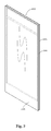
- FIG. 3 is a perspective view of the sealed transparent LCD assembly of FIGS. 1-2 .
- FIG. 4 is a front planar view of the sealed transparent LCD assembly, showing the section lines A-A and B-B.
- FIG. 5 is a section view taken along the section line A-A shown in FIG. 4 and indicating Detail A and Detail B.
- FIG. 6 is a section view taken along the section line B-B shown in FIG. 4 and indicating Detail C.
- FIG. 7 is a detailed section view of Detail A shown in FIG. 5 .
- FIG. 8 is a detailed section view of Detail B shown in FIG. 5 .
- FIG. 9 is a detailed section view of Detail C shown in FIG. 6 .
- FIG. 10 is a perspective view of a partially assembled exemplary embodiment of a sealed transparent LCD assembly.
- FIG. 11 is a simplified partial view of an exemplary embodiment of the lower thermal plate.
- FIG. 12 is a simplified partial view of an exemplary embodiment of the upper thermal plate.
- Embodiments of the invention are described herein with reference to illustrations that are schematic illustrations of idealized embodiments (and intermediate structures) of the invention. As such, variations from the shapes of the illustrations as a result, for example, of manufacturing techniques and/or tolerances, are to be expected. Thus, embodiments of the invention should not be construed as limited to the particular shapes of regions illustrated herein but are to include deviations in shapes that result, for example, from manufacturing.
- FIG. 1 is a perspective view of a display case having an exemplary sealed transparent LCD assembly 200 .
- the display case includes a housing 105 , to which a door frame assembly 100 is fastened.
- a cavity 110 is provided below the door frame assembly 100 where various electronic devices 111 for operating the transparent LCD assembly 200 can be located.
- the electrical devices 111 may include any or all of the following: timing and control board (TCON), video player, hard drive/storage, microprocessor/CPU, wireless transmitter/receiver, cellular data transmitter/receiver, and internet connectivity. At least some of the electrical devices 111 are in electrical communication with the transparent LCD 230 .
- FIG. 2 is a perspective view of the display case of FIG. 1 where the door has been opened.
- FIG. 3 is a perspective view of the sealed transparent LCD assembly 200 of FIGS. 1-2 .
- the assembly includes a spacer 300 which is sandwiched between a front glass 225 and rear glass 205 .
- These components are preferably sealed together with an inert gas filling the sealed enclosure.
- argon gas has been found to be preferred in the exemplary embodiments.
- the spacer 300 is the Super Spacer® Standard from Quanex in Cambridge, Ohio. www.quanex.com.
- the spacer 300 would be a flexible foam that contains a desiccant and has a pressure sensitive acrylic adhesive on the front and back edges of the spacer which would be used to bond with the front and rear glass.
- FIG. 4 is a front planar view of the sealed transparent LCD assembly, showing the section lines A-A and B-B.
- FIG. 5 is a section view taken along the section line A-A shown in FIG. 4 and indicating Detail A and Detail B.
- FIG. 6 is a section view taken along the section line B-B shown in FIG. 4 and indicating Detail C.
- FIG. 7 is a detailed section view of Detail A shown in FIG. 5 .
- a top thermal plate 216 is preferably bonded to the rear glass 205 .
- the top thermal plate 216 is preferably bonded to the rear glass 205 through adhesive transfer tape.
- An exemplary adhesive transfer tape for this purpose would be 468 MP, available commercially from 3MTM of St. Paul, Minn. www.3M.com/converter.
- a printed circuit board (PCB) 246 containing a plurality of LEDs 276 is preferably attached to the top thermal plate 216 and is preferably in conductive thermal communication with the top thermal plate 216 as well. In this way, heat that is generated by the LEDs 276 can be transmitted to the PCB 246 , top thermal plate 216 , and eventually transferring to the rear glass 205 where the heat can dissipate through natural or forced convection.
- PCB printed circuit board
- the LEDs 276 are placed adjacent to the edge of a light guide 220 which is sandwiched between a rear bracket 211 and a front bracket 236 .
- the light guide 220 is only constrained from movement towards the front or back of the assembly, but is not constrained from movement towards the top or sides of the assembly.
- the light guide 220 is secured such that it is capable of thermal expansion/contraction in the X-Y direction (horizontal and vertical when observing the LCD), but is fixed in the Z direction (into/out of the assembly when observing the LCD). It could also be said that the light guide 220 is constrained so that it cannot move towards the front or rear glass but otherwise is permitted to float between the rear bracket 211 and front bracket 236 .
- the light guide 220 would be the Acrylite® LED Endlighten product available from Evonik Industries. www.acrylite-shop.com.
- the light guide 220 would contain microscopic diffuse particulate that is homogeneously scattered throughout the sheet.
- the light emitted from the LEDs 276 and 275 is permitted to exit both the front and rear surfaces of the light guide 220 (in this way, the light guide 220 could be referred to as a ‘two way light guide’).
- the light is permitted to exit the rear of the light guide 220 so as to illuminate the products within the display case.
- the amount of light permitted to exit the rear surface of the light guide 220 is at least 20% of the amount of light permitted to exit the front surface of the light guide 220 .
- the transparent LCD 230 is preferably attached to a front surface of the front bracket 236 through a layer of adhesive 241 which would preferably be applied around the perimeter of the LCD 230 .
- the adhesive 241 would be VHB tape and preferably 5052 VHB Tape available commercially from 3MTM of St. Paul, Minn. www.3M.com.
- FIG. 8 is a detailed section view of Detail B shown in FIG. 5 .
- a bottom thermal plate 215 is preferably bonded to the rear glass 205 .
- the bottom thermal plate 215 is preferably bonded to the rear glass 205 through adhesive transfer tape.
- An exemplary adhesive transfer tape for this purpose would be 468 MP, available commercially from 3MTM of St. Paul, Minn. www.3M.com/converter.
- a printed circuit board (PCB) 245 containing a plurality of LEDs 275 is preferably attached to the bottom thermal plate 215 and is preferably in conductive thermal communication with the bottom thermal plate 215 as well. In this way, heat that is generated by the LEDs 275 can be transmitted to the PCB 245 , bottom thermal plate 215 , and eventually transferring to the rear glass 205 where the heat can dissipate through natural or forced convection.
- PCB printed circuit board
- the LEDs 275 are placed adjacent to the edge of a light guide 220 which is sandwiched between a rear bracket 211 and a front bracket 236 .
- the light guide 220 is preferably only constrained from movement towards the front or back of the assembly, but is not contained from movement towards the top or sides of the assembly.
- FIG. 9 is a detailed section view of Detail C shown in FIG. 6 .
- FIG. 10 is a perspective view of a partially assembled exemplary embodiment of a sealed transparent LCD assembly. This view shows the rear glass 205 with the spacer 300 attached around the perimeter of the glass 205 . Also shown is the rear bracket 211 which may be attached to the rear glass 205 as well.
- FIG. 11 is a simplified partial view of an exemplary embodiment of the lower thermal plate 215 .
- the lower thermal plate 215 would extend horizontally as far as possible, preferably to the same horizontal width as the LCD 230 and may extend 4-14 inches in vertical width, depending on the application.
- electrical devices 400 are mounted to the thermal plate 215 and can include, but are not limited to: power modules, wireless or satellite receiver/transmitter, video player, hard drive, microprocessor, and printed circuit boards. Although shown attached to the lower thermal plate 215 , electrical devices 400 could also be mounted to the upper thermal plate 216 .
- the electrical devices 400 are also in conductive thermal communication with the thermal plate 215 / 216 so that heat which is generated by the electrical devices 400 can be transferred to the thermal plate 215 / 216 and eventually to the rear glass 205 , where it can be removed by natural or forced convection.
- FIG. 12 is a simplified partial view of an exemplary embodiment of the upper thermal plate.
- the upper thermal plate 216 would extend horizontally as far as possible, preferably to the same horizontal width as the LCD 230 .
- the upper thermal plate 216 may also extend 4-14 inches in vertical width, depending on the application.
- the lower thermal plate 215 and the upper thermal plate 216 are within 15% of the same surface area.
- the plates 215 / 216 are substantially the same surface area. This is not required, however, as some embodiments may require a larger surface area for the plate which would contain the electrical devices 400 , or a larger surface area for the top plate 216 as compared to the bottom plate 215 .
- the thermal plates are both metallic, and most preferably aluminum, but they can be any material that has good thermal conductivity.
- cooling system can be used with any number of display case designs, either temperature controlled or not, and with doors that open, or glass that remains stationary. Although shown here with a transparent LCD, the cooling system could be used with a traditional backlit LCD as well.
Abstract
Description
Claims (17)
Priority Applications (3)
| Application Number | Priority Date | Filing Date | Title |
|---|---|---|---|
| US14/740,865 US9500896B2 (en) | 2014-06-16 | 2015-06-16 | Cooling system for liquid crystal display |
| US15/357,917 US9733420B2 (en) | 2014-06-16 | 2016-11-21 | Cooling system for liquid crystal display |
| US15/665,618 US10705288B2 (en) | 2014-06-16 | 2017-08-01 | Thermal management system for a transparent electronic display located in an access panel of a display case |
Applications Claiming Priority (2)
| Application Number | Priority Date | Filing Date | Title |
|---|---|---|---|
| US201462012785P | 2014-06-16 | 2014-06-16 | |
| US14/740,865 US9500896B2 (en) | 2014-06-16 | 2015-06-16 | Cooling system for liquid crystal display |
Related Child Applications (1)
| Application Number | Title | Priority Date | Filing Date |
|---|---|---|---|
| US15/357,917 Continuation US9733420B2 (en) | 2014-06-16 | 2016-11-21 | Cooling system for liquid crystal display |
Publications (2)
| Publication Number | Publication Date |
|---|---|
| US20150362792A1 US20150362792A1 (en) | 2015-12-17 |
| US9500896B2 true US9500896B2 (en) | 2016-11-22 |
Family
ID=54836046
Family Applications (3)
| Application Number | Title | Priority Date | Filing Date |
|---|---|---|---|
| US14/740,865 Active 2035-07-27 US9500896B2 (en) | 2014-06-16 | 2015-06-16 | Cooling system for liquid crystal display |
| US15/357,917 Active US9733420B2 (en) | 2014-06-16 | 2016-11-21 | Cooling system for liquid crystal display |
| US15/665,618 Active 2035-10-23 US10705288B2 (en) | 2014-06-16 | 2017-08-01 | Thermal management system for a transparent electronic display located in an access panel of a display case |
Family Applications After (2)
| Application Number | Title | Priority Date | Filing Date |
|---|---|---|---|
| US15/357,917 Active US9733420B2 (en) | 2014-06-16 | 2016-11-21 | Cooling system for liquid crystal display |
| US15/665,618 Active 2035-10-23 US10705288B2 (en) | 2014-06-16 | 2017-08-01 | Thermal management system for a transparent electronic display located in an access panel of a display case |
Country Status (1)
| Country | Link |
|---|---|
| US (3) | US9500896B2 (en) |
Cited By (39)
| Publication number | Priority date | Publication date | Assignee | Title |
|---|---|---|---|---|
| US20140113540A1 (en) * | 2012-10-16 | 2014-04-24 | Manufacturing Resources International, Inc. | Back Pan Cooling Assembly for Electronic Display |
| US9661939B2 (en) | 2014-06-16 | 2017-05-30 | Manufacturing Resources International, Inc. | Wireless video transmission system for liquid crystal display |
| US9684124B2 (en) | 2014-06-16 | 2017-06-20 | Manufacturing Resources International, Inc. | LED assembly for transparent liquid crystal display |
| US9733420B2 (en) | 2014-06-16 | 2017-08-15 | Manufacturing Resources Internationak, Inc. | Cooling system for liquid crystal display |
| US9832847B2 (en) | 2014-10-09 | 2017-11-28 | Manufacturing Resources International, Inc. | System for decreasing energy usage of a transparent LCD display case |
| US9835893B2 (en) | 2008-03-03 | 2017-12-05 | Manufacturing Resources International, Inc. | Heat exchanger for back to back electronics displays |
| US9881528B2 (en) | 2011-10-13 | 2018-01-30 | Manufacturing Resources International, Inc. | Transparent liquid crystal display on display case |
| US9894800B2 (en) | 2008-03-03 | 2018-02-13 | Manufacturing Resources International, Inc. | Constricted convection cooling system for an electronic display |
| US9983427B2 (en) | 2014-06-16 | 2018-05-29 | Manufacturing Resources International, Inc. | Sealed transparent liquid crystal display assembly |
| US10080316B2 (en) | 2009-11-13 | 2018-09-18 | Manufacturing Resources International, Inc. | Electronic display assembly having thermal cooling plate and optional convective air cooling loop |
| US10088702B2 (en) | 2013-07-08 | 2018-10-02 | Manufacturing Resources International, Inc. | Figure eight closed loop cooling system for electronic display |
| US10182665B2 (en) | 2014-10-15 | 2019-01-22 | Manufacturing Resources International, Inc. | System and method for preventing damage to products |
| US10194564B2 (en) | 2014-04-30 | 2019-01-29 | Manufacturing Resources International, Inc. | Back to back electronic display assembly |
| US10269038B2 (en) | 2014-06-16 | 2019-04-23 | Manufacturing Resources International, Inc. | System for tracking and analyzing consumption |
| US10278311B2 (en) | 2015-02-17 | 2019-04-30 | Manufacturing Resources International, Inc. | Perimeter ventilation system |
| US10314212B2 (en) | 2008-12-18 | 2019-06-04 | Manufacturing Resources International, Inc. | System for cooling an electronic image assembly with circulating gas and ambient gas |
| US20190221144A1 (en) * | 2018-01-17 | 2019-07-18 | Anthony, Inc. | Door for mounting a removable electronic display |
| US10398066B2 (en) | 2017-04-27 | 2019-08-27 | Manufacturing Resources International, Inc. | System and method for preventing display bowing |
| US10420257B2 (en) | 2008-03-26 | 2019-09-17 | Manufacturing Resources International, Inc. | System and method for maintaining a consistent temperature gradient across an electronic display |
| US10467844B2 (en) | 2016-03-02 | 2019-11-05 | Manufacturing Resources International, Inc. | Vending machines having a transparent display |
| US10485113B2 (en) | 2017-04-27 | 2019-11-19 | Manufacturing Resources International, Inc. | Field serviceable and replaceable display |
| US10506740B2 (en) | 2008-03-03 | 2019-12-10 | Manufacturing Resources International, Inc. | Electronic display with cooling |
| US10514722B1 (en) | 2019-03-29 | 2019-12-24 | Anthony, Inc. | Door for mounting a removable electronic display |
| US10524384B2 (en) | 2013-03-15 | 2019-12-31 | Manufacturing Resources International, Inc. | Cooling assembly for an electronic display |
| US10524397B2 (en) | 2013-03-15 | 2019-12-31 | Manufacturing Resources International, Inc. | Heat exchanger assembly for an electronic display |
| US10559965B2 (en) | 2017-09-21 | 2020-02-11 | Manufacturing Resources International, Inc. | Display assembly having multiple charging ports |
| US10649273B2 (en) | 2014-10-08 | 2020-05-12 | Manufacturing Resources International, Inc. | LED assembly for transparent liquid crystal display and static graphic |
| US10692407B2 (en) | 2016-07-08 | 2020-06-23 | Manufacturing Resources International, Inc. | Mirror having an integrated electronic display |
| US10795413B1 (en) | 2019-04-03 | 2020-10-06 | Manufacturing Resources International, Inc. | Electronic display assembly with a channel for ambient air in an access panel |
| US10820445B2 (en) | 2016-03-04 | 2020-10-27 | Manufacturing Resources International, Inc. | Cooling system for double sided display assembly |
| US10827656B2 (en) | 2008-12-18 | 2020-11-03 | Manufacturing Resources International, Inc. | System for cooling an electronic image assembly with circulating gas and ambient gas |
| US11019735B2 (en) | 2018-07-30 | 2021-05-25 | Manufacturing Resources International, Inc. | Housing assembly for an integrated display unit |
| US11096317B2 (en) | 2019-02-26 | 2021-08-17 | Manufacturing Resources International, Inc. | Display assembly with loopback cooling |
| US11470749B2 (en) | 2020-10-23 | 2022-10-11 | Manufacturing Resources International, Inc. | Forced air cooling for display assemblies using centrifugal fans |
| US11477923B2 (en) | 2020-10-02 | 2022-10-18 | Manufacturing Resources International, Inc. | Field customizable airflow system for a communications box |
| US11744054B2 (en) | 2021-08-23 | 2023-08-29 | Manufacturing Resources International, Inc. | Fan unit for providing improved airflow within display assemblies |
| US11762231B2 (en) | 2021-08-23 | 2023-09-19 | Manufacturing Resources International, Inc. | Display assemblies inducing turbulent flow |
| US11778757B2 (en) | 2020-10-23 | 2023-10-03 | Manufacturing Resources International, Inc. | Display assemblies incorporating electric vehicle charging equipment |
| US11919393B2 (en) | 2021-08-23 | 2024-03-05 | Manufacturing Resources International, Inc. | Display assemblies inducing relatively turbulent flow and integrating electric vehicle charging equipment |
Families Citing this family (13)
| Publication number | Priority date | Publication date | Assignee | Title |
|---|---|---|---|---|
| US9750355B1 (en) * | 2016-03-02 | 2017-09-05 | Pepsico, Inc. | Refrigerated merchandise display system |
| JP2020502777A (en) * | 2016-09-27 | 2020-01-23 | イヌル ゲーエムベーハー | Non-destructive integration of electronic devices |
| KR102627962B1 (en) | 2016-12-12 | 2024-01-23 | 엘지전자 주식회사 | Refrigerator |
| KR102273092B1 (en) * | 2016-12-12 | 2021-07-06 | 엘지전자 주식회사 | Refrigerator |
| KR20180067360A (en) * | 2016-12-12 | 2018-06-20 | 엘지전자 주식회사 | Refrigerator |
| US10769666B2 (en) | 2017-08-10 | 2020-09-08 | Cooler Screens Inc. | Intelligent marketing and advertising platform |
| US11768030B2 (en) | 2017-08-10 | 2023-09-26 | Cooler Screens Inc. | Smart movable closure system for cooling cabinet |
| US10672032B2 (en) * | 2017-08-10 | 2020-06-02 | Cooler Screens Inc. | Intelligent marketing and advertising platform |
| US11698219B2 (en) | 2017-08-10 | 2023-07-11 | Cooler Screens Inc. | Smart movable closure system for cooling cabinet |
| US11763252B2 (en) | 2017-08-10 | 2023-09-19 | Cooler Screens Inc. | Intelligent marketing and advertising platform |
| CN108873488B (en) * | 2018-06-29 | 2021-04-20 | 深圳市华星光电半导体显示技术有限公司 | Ultraviolet irradiation machine and equipment for manufacturing alignment film |
| WO2021014209A1 (en) * | 2019-07-21 | 2021-01-28 | Trax Technology Solutions Pte Ltd. | Electronic visual displays in retail stores |
| CN112617523A (en) * | 2020-12-21 | 2021-04-09 | 南京帕芙莲饰品有限公司 | Jewelry replacement theftproof show stand |
Citations (21)
| Publication number | Priority date | Publication date | Assignee | Title |
|---|---|---|---|---|
| US20020075552A1 (en) * | 2000-07-25 | 2002-06-20 | Poll David L. | Electrochromic windows and method of making the same |
| US20020187575A1 (en) * | 2001-04-27 | 2002-12-12 | Semiconductor Energy Laboratory Co., Ltd. | Display device and manufacturing method thereof |
| US20050265019A1 (en) | 2004-05-26 | 2005-12-01 | Gelcore Llc | LED lighting systems for product display cases |
| US20070151274A1 (en) | 2005-12-30 | 2007-07-05 | Hussmann Corporation | LED canopy light fixture |
| US20070171647A1 (en) | 2006-01-25 | 2007-07-26 | Anthony, Inc. | Control system for illuminated display case |
| US20080055534A1 (en) | 2006-08-30 | 2008-03-06 | Nec Lcd Technologies, Ltd. | Back light unit and liquid crystal display device using the same |
| US20080284942A1 (en) | 2004-08-18 | 2008-11-20 | Kazutoshi Mahama | Backlight Device and Transmission Type Liquid Crystal Display Apparatus |
| US20090002990A1 (en) | 2007-06-29 | 2009-01-01 | Aaron James Becker | Led lighting assemblies for display cases |
| US20100162747A1 (en) | 2008-12-31 | 2010-07-01 | Timothy Allen Hamel | Refrigerator with a convertible compartment |
| US7922381B2 (en) | 2003-06-26 | 2011-04-12 | Samsung Electronics Co., Ltd. | Two-way backlight assembly and two-way liquid crystal display apparatus having the same |
| US20110083460A1 (en) | 2008-10-07 | 2011-04-14 | James Thomas | LED illuminated member within a refrigerated display case |
| US20110116231A1 (en) | 2009-11-13 | 2011-05-19 | Manufacturing Resources International, Inc. | Field serviceable electronic display |
| US20130016296A1 (en) * | 2010-04-07 | 2013-01-17 | Yoshimasa Fujita | Organic electroluminescence element, organic electroluminescence display, and organic electroluminescence display apparatus |
| US20130063326A1 (en) | 2011-03-02 | 2013-03-14 | Christopher K. Riegel | Translucent Digital Display System |
| US20130265525A1 (en) | 2011-10-13 | 2013-10-10 | Manufacturing Resources International, Inc. | Lighting System for Transparent Liquid Crystal Display |
| US20130271696A1 (en) | 2011-10-13 | 2013-10-17 | Manufacturing Resources International, Inc. | Transparent Liquid Crystal Display on Display Case |
| US20140078407A1 (en) | 2012-03-06 | 2014-03-20 | Planar Systems, Inc. | Transparent electronic image display apparatus for refrigerated merchandisers and the like |
| US20140085564A1 (en) * | 2012-09-26 | 2014-03-27 | Apple Inc. | Computer led bar and thermal architecture features |
| US8683745B2 (en) | 2011-05-10 | 2014-04-01 | Anthony, Inc. | Refrigerated display case door with transparent LCD panel |
| US20140104538A1 (en) | 2012-10-17 | 2014-04-17 | Samsung Electronics Co., Ltd. | Liquid crystal display |
| US20140144083A1 (en) | 2011-05-10 | 2014-05-29 | Anthony, Inc. | Display case door with transparent lcd panel |
Family Cites Families (76)
| Publication number | Priority date | Publication date | Assignee | Title |
|---|---|---|---|---|
| US3629972A (en) | 1970-02-09 | 1971-12-28 | Ardco Inc | Refrigerator door construction |
| US4040726A (en) | 1976-03-12 | 1977-08-09 | Paca Francis B | See-through mirror with spaced reflective strips |
| US4299092A (en) | 1979-12-07 | 1981-11-10 | Tyler Refrigeration Corporation | Energy conserving refrigerated merchandiser display case |
| US4371870A (en) | 1980-09-02 | 1983-02-01 | Mcdonnell Douglas Corporation | Fail transparent LCD display with backup |
| NZ219198A (en) | 1987-02-05 | 1990-11-27 | Sensasel Worldwide Ltd | Illuminated sign with proximity sensor |
| US4950344A (en) | 1988-12-05 | 1990-08-21 | Lauren Manufacturing Company | Method of manufacturing multiple-pane sealed glazing units |
| KR20020040989A (en) | 2000-11-25 | 2002-05-31 | 주식회사 현대 디스플레이 테크놀로지 | Backlight unit for irradiating to upper and lower |
| US7259730B2 (en) | 2001-06-12 | 2007-08-21 | Vlyte Innovations, Ltd. | Window, a method for displaying a character on a window, and a visual display panel |
| US20030062813A1 (en) | 2001-07-19 | 2003-04-03 | Cording Christopher R. | Energy-free refrigeration door and method for making the same |
| TW594119B (en) | 2001-12-21 | 2004-06-21 | Au Optronics Corp | Backlight module for thin film transistor liquid crystal display |
| US20030139169A1 (en) * | 2002-01-18 | 2003-07-24 | Gregory Arreazola | Combination insulated container and entertainment center |
| US8354927B2 (en) | 2002-06-11 | 2013-01-15 | Intelligent Technologies International, Inc. | Shipping container monitoring based on door status |
| KR100472759B1 (en) | 2002-11-26 | 2005-03-08 | 주식회사 대우일렉트로닉스 | The method for controlling back-light of lcd screen equipped on a refrigerator front control panel |
| ATE491119T1 (en) | 2004-08-27 | 2010-12-15 | Arcelik As | HOUSEHOLD APPLIANCE |
| WO2006055873A2 (en) | 2004-11-17 | 2006-05-26 | Fusion Optix, Inc. | Enhanced electroluminescent sign |
| WO2006067777A2 (en) | 2004-12-23 | 2006-06-29 | Nualight Limited | Display cabinet illumination |
| US20060284788A1 (en) | 2005-06-21 | 2006-12-21 | Robinson Douglas L | Infinity tunnel display system with floating dynamic image |
| EP1960723A4 (en) | 2005-12-12 | 2013-02-27 | Lg Electronics Inc | A control unit for refrigerator and method controlling the same |
| GB2433637A (en) | 2005-12-21 | 2007-06-27 | 3M Innovative Properties Co | Semi-transparent retroreflective material |
| US20070195535A1 (en) | 2006-02-23 | 2007-08-23 | Anthony, Inc. | Reflector system for led illuminated display case |
| US7596958B2 (en) | 2006-03-20 | 2009-10-06 | Hussmann Corporation | Refrigeration system with fiber optic sensing |
| US7670018B2 (en) | 2006-05-16 | 2010-03-02 | Lg Electronics Inc. | Illumination device for refrigerator and method of controlling the same |
| CA2658928A1 (en) | 2006-07-24 | 2008-01-31 | Chun Jiang Luo | Decorative door for cooler |
| JP5119636B2 (en) | 2006-09-27 | 2013-01-16 | ソニー株式会社 | Display device and display method |
| US7733439B2 (en) | 2007-04-30 | 2010-06-08 | Qualcomm Mems Technologies, Inc. | Dual film light guide for illuminating displays |
| US8578081B1 (en) | 2007-07-25 | 2013-11-05 | Robert Louis Fils | Docking station for an electronic device |
| US7413233B1 (en) | 2007-08-28 | 2008-08-19 | Man-Young Jung | Vehicle sun visor with auto-shading prompter screen |
| US8497972B2 (en) | 2009-11-13 | 2013-07-30 | Manufacturing Resources International, Inc. | Thermal plate with optional cooling loop in electronic display |
| US8358397B2 (en) | 2008-03-03 | 2013-01-22 | Manufacturing Resources International, Inc. | System for cooling an electronic display |
| US20100026912A1 (en) | 2008-07-31 | 2010-02-04 | Solomon Ho | Multifunction display system |
| US8380347B2 (en) | 2008-10-13 | 2013-02-19 | Brent D. Garson | Method and apparatus for use in a vending machine |
| EP2199140B1 (en) | 2008-12-16 | 2013-05-08 | Johnson Controls GmbH | Instrument-display with a transparent appliqué over a display |
| TW201028744A (en) | 2009-01-23 | 2010-08-01 | Taiwan Nanotechnology Corp | A light guide plate |
| WO2010116202A1 (en) | 2009-04-09 | 2010-10-14 | Freescale Semiconductor, Inc. | A method and system arranged for filtering an image |
| KR101712100B1 (en) | 2010-01-12 | 2017-03-03 | 삼성전자 주식회사 | Cooling system and display apparatus using the same |
| AU2010100496B4 (en) | 2010-05-21 | 2013-08-22 | Maslen Technology Australia Pty Ltd | Internal lighting for refrigerated display cabinets |
| IT1400746B1 (en) | 2010-06-30 | 2013-07-02 | Damian S R L | AUTOMATIC PRODUCT DISTRIBUTOR MACHINE |
| CN101949526B (en) | 2010-07-12 | 2012-11-14 | 深圳市华星光电技术有限公司 | Side-entering type backlight module and back-plate heat radiating structure thereof |
| US8665606B2 (en) | 2010-07-16 | 2014-03-04 | Mediatek Inc. | Electronic device having circuit board with co-layout design of multiple connector placement sites and related circuit board thereof |
| KR101843337B1 (en) | 2010-10-28 | 2018-03-30 | 삼성전자주식회사 | Display module and display system |
| US20120105428A1 (en) | 2010-10-28 | 2012-05-03 | Microsoft Corporation | Transparent display configuration modes |
| US8417376B1 (en) | 2011-01-28 | 2013-04-09 | Christopher M. Smolen | Method and means for viewing selecting and taking action relative to an item of a group of items |
| US20120206500A1 (en) | 2011-02-15 | 2012-08-16 | Micron Technology, Inc. | Video data dependent adjustment of display drive |
| US20120275477A1 (en) | 2011-04-28 | 2012-11-01 | Martin Ole Berendt | Suppression of coherence effects in fiber lasers |
| CN202067045U (en) | 2011-05-10 | 2011-12-07 | 深圳市华星光电技术有限公司 | Liquid crystal display device and rear shell of liquid crystal display device |
| US20160155873A1 (en) | 2011-11-14 | 2016-06-02 | Prism Solar Technologies Incorporated | Flexible photovoltaic module |
| KR20130056028A (en) | 2011-11-21 | 2013-05-29 | 엘지전자 주식회사 | Showcase system including transparent display panel and method for operating the same |
| TWI526888B (en) | 2011-12-20 | 2016-03-21 | 友達光電股份有限公司 | Vending machine and operating system and operating method thereof |
| JP5173088B1 (en) | 2012-02-28 | 2013-03-27 | パナソニック株式会社 | COMMUNICATION SYSTEM, ELECTRIC DEVICE, AND PORTABLE TERMINAL DEVICE |
| US9671566B2 (en) | 2012-06-11 | 2017-06-06 | Magic Leap, Inc. | Planar waveguide apparatus with diffraction element(s) and system employing same |
| WO2014006490A1 (en) | 2012-07-04 | 2014-01-09 | Kraslex Ltd. | Display module and structure with such module |
| AU2012385281B2 (en) | 2012-07-09 | 2017-08-17 | Red Bull Gmbh | Transparent display device |
| US8704448B2 (en) | 2012-09-06 | 2014-04-22 | Cooledge Lighting Inc. | Wiring boards for array-based electronic devices |
| CN202815379U (en) | 2012-09-13 | 2013-03-20 | 宁波永望电子科技有限公司 | Liquid crystal display |
| CN104685554A (en) | 2012-09-28 | 2015-06-03 | 松下知识产权经营株式会社 | Display device |
| US9519185B2 (en) | 2012-10-12 | 2016-12-13 | Manufacturing Resources International, Inc. | Lighting system for transparent liquid crystal display |
| US20140204452A1 (en) | 2013-01-21 | 2014-07-24 | sp3 nanotech LLC | Switchable lens apparatus and method |
| KR102141459B1 (en) * | 2013-03-22 | 2020-08-05 | 가부시키가이샤 한도오따이 에네루기 켄큐쇼 | Liquid crystal display device |
| KR101728196B1 (en) | 2013-04-26 | 2017-04-18 | 엘지전자 주식회사 | Refrigerator |
| US9702619B2 (en) | 2013-07-31 | 2017-07-11 | Whirlpool Corporation | Controlled, dynamic lighting of interior of appliance |
| GB2538884A (en) | 2013-12-20 | 2016-11-30 | Lockheed Corp | Condensation inhibiting layer, method of forming the layer, and condensation inhibiting device |
| US9451656B2 (en) | 2014-02-28 | 2016-09-20 | At&T Mobility Ii Llc | Enabling wireless connectivity for devices |
| US10527276B2 (en) | 2014-04-17 | 2020-01-07 | Manufacturing Resources International, Inc. | Rod as a lens element for light emitting diodes |
| AU2015277337B2 (en) | 2014-06-16 | 2018-05-31 | Manufacturing Resources International, Inc. | Transparent LCD assembly with display case |
| US9535293B2 (en) | 2014-06-16 | 2017-01-03 | Manufacturing Resources International, Inc. | Sealed transparent liquid crystal display assembly |
| US9500896B2 (en) | 2014-06-16 | 2016-11-22 | Manufacturing Resources International, Inc. | Cooling system for liquid crystal display |
| US9526352B2 (en) | 2014-06-16 | 2016-12-27 | Manufacturing Resources International, Inc. | Wireless video transmission system for liquid crystal display |
| US9500801B2 (en) | 2014-06-16 | 2016-11-22 | Manufacturing Resources International, Inc. | LED assembly for transparent liquid crystal display |
| US9633366B2 (en) | 2014-06-16 | 2017-04-25 | Manufacturing Resources International, Inc. | System for tracking and analyzing display case usage |
| JP6506648B2 (en) | 2014-07-31 | 2019-04-24 | 株式会社半導体エネルギー研究所 | Display device |
| US20160091755A1 (en) | 2014-09-25 | 2016-03-31 | Manufacturing Resources International, Inc. | Optical Assembly for Transparent LCD Display Case |
| WO2016053670A1 (en) * | 2014-10-01 | 2016-04-07 | True Manufacturing Co., Inc. | Edge-lit door for refrigerator unit |
| US10649273B2 (en) | 2014-10-08 | 2020-05-12 | Manufacturing Resources International, Inc. | LED assembly for transparent liquid crystal display and static graphic |
| US9832847B2 (en) | 2014-10-09 | 2017-11-28 | Manufacturing Resources International, Inc. | System for decreasing energy usage of a transparent LCD display case |
| US10182665B2 (en) | 2014-10-15 | 2019-01-22 | Manufacturing Resources International, Inc. | System and method for preventing damage to products |
| EP3422907A4 (en) | 2016-03-02 | 2019-09-18 | Manufacturing Resources International, Inc. | Vending machine having a transparent display |
-
2015
- 2015-06-16 US US14/740,865 patent/US9500896B2/en active Active
-
2016
- 2016-11-21 US US15/357,917 patent/US9733420B2/en active Active
-
2017
- 2017-08-01 US US15/665,618 patent/US10705288B2/en active Active
Patent Citations (21)
| Publication number | Priority date | Publication date | Assignee | Title |
|---|---|---|---|---|
| US20020075552A1 (en) * | 2000-07-25 | 2002-06-20 | Poll David L. | Electrochromic windows and method of making the same |
| US20020187575A1 (en) * | 2001-04-27 | 2002-12-12 | Semiconductor Energy Laboratory Co., Ltd. | Display device and manufacturing method thereof |
| US7922381B2 (en) | 2003-06-26 | 2011-04-12 | Samsung Electronics Co., Ltd. | Two-way backlight assembly and two-way liquid crystal display apparatus having the same |
| US20050265019A1 (en) | 2004-05-26 | 2005-12-01 | Gelcore Llc | LED lighting systems for product display cases |
| US20080284942A1 (en) | 2004-08-18 | 2008-11-20 | Kazutoshi Mahama | Backlight Device and Transmission Type Liquid Crystal Display Apparatus |
| US20070151274A1 (en) | 2005-12-30 | 2007-07-05 | Hussmann Corporation | LED canopy light fixture |
| US20070171647A1 (en) | 2006-01-25 | 2007-07-26 | Anthony, Inc. | Control system for illuminated display case |
| US20080055534A1 (en) | 2006-08-30 | 2008-03-06 | Nec Lcd Technologies, Ltd. | Back light unit and liquid crystal display device using the same |
| US20090002990A1 (en) | 2007-06-29 | 2009-01-01 | Aaron James Becker | Led lighting assemblies for display cases |
| US20110083460A1 (en) | 2008-10-07 | 2011-04-14 | James Thomas | LED illuminated member within a refrigerated display case |
| US20100162747A1 (en) | 2008-12-31 | 2010-07-01 | Timothy Allen Hamel | Refrigerator with a convertible compartment |
| US20110116231A1 (en) | 2009-11-13 | 2011-05-19 | Manufacturing Resources International, Inc. | Field serviceable electronic display |
| US20130016296A1 (en) * | 2010-04-07 | 2013-01-17 | Yoshimasa Fujita | Organic electroluminescence element, organic electroluminescence display, and organic electroluminescence display apparatus |
| US20130063326A1 (en) | 2011-03-02 | 2013-03-14 | Christopher K. Riegel | Translucent Digital Display System |
| US8683745B2 (en) | 2011-05-10 | 2014-04-01 | Anthony, Inc. | Refrigerated display case door with transparent LCD panel |
| US20140144083A1 (en) | 2011-05-10 | 2014-05-29 | Anthony, Inc. | Display case door with transparent lcd panel |
| US20130265525A1 (en) | 2011-10-13 | 2013-10-10 | Manufacturing Resources International, Inc. | Lighting System for Transparent Liquid Crystal Display |
| US20130271696A1 (en) | 2011-10-13 | 2013-10-17 | Manufacturing Resources International, Inc. | Transparent Liquid Crystal Display on Display Case |
| US20140078407A1 (en) | 2012-03-06 | 2014-03-20 | Planar Systems, Inc. | Transparent electronic image display apparatus for refrigerated merchandisers and the like |
| US20140085564A1 (en) * | 2012-09-26 | 2014-03-27 | Apple Inc. | Computer led bar and thermal architecture features |
| US20140104538A1 (en) | 2012-10-17 | 2014-04-17 | Samsung Electronics Co., Ltd. | Liquid crystal display |
Cited By (80)
| Publication number | Priority date | Publication date | Assignee | Title |
|---|---|---|---|---|
| US10506738B2 (en) | 2008-03-03 | 2019-12-10 | Manufacturing Resources International, Inc. | Constricted convection cooling for an electronic display |
| US11596081B2 (en) | 2008-03-03 | 2023-02-28 | Manufacturing Resources International, Inc. | Electronic display with cooling |
| US11540418B2 (en) | 2008-03-03 | 2022-12-27 | Manufacturing Resources International, Inc. | Electronic display with cooling |
| US10506740B2 (en) | 2008-03-03 | 2019-12-10 | Manufacturing Resources International, Inc. | Electronic display with cooling |
| US11013142B2 (en) | 2008-03-03 | 2021-05-18 | Manufacturing Resources International, Inc. | Electronic display with cooling |
| US9835893B2 (en) | 2008-03-03 | 2017-12-05 | Manufacturing Resources International, Inc. | Heat exchanger for back to back electronics displays |
| US10721836B2 (en) | 2008-03-03 | 2020-07-21 | Manufacturing Resources International, Inc. | Electronic display with cooling |
| US9894800B2 (en) | 2008-03-03 | 2018-02-13 | Manufacturing Resources International, Inc. | Constricted convection cooling system for an electronic display |
| US10420257B2 (en) | 2008-03-26 | 2019-09-17 | Manufacturing Resources International, Inc. | System and method for maintaining a consistent temperature gradient across an electronic display |
| US10827656B2 (en) | 2008-12-18 | 2020-11-03 | Manufacturing Resources International, Inc. | System for cooling an electronic image assembly with circulating gas and ambient gas |
| US10314212B2 (en) | 2008-12-18 | 2019-06-04 | Manufacturing Resources International, Inc. | System for cooling an electronic image assembly with circulating gas and ambient gas |
| US11191193B2 (en) | 2008-12-18 | 2021-11-30 | Manufacturing Resources International, Inc. | System for cooling an electronic image assembly with circulating gas and ambient gas |
| US10080316B2 (en) | 2009-11-13 | 2018-09-18 | Manufacturing Resources International, Inc. | Electronic display assembly having thermal cooling plate and optional convective air cooling loop |
| US10736245B2 (en) | 2009-11-13 | 2020-08-04 | Manufacturing Resources International, Inc. | Electronic display assembly with combined conductive and convective cooling |
| US9881528B2 (en) | 2011-10-13 | 2018-01-30 | Manufacturing Resources International, Inc. | Transparent liquid crystal display on display case |
| US10417943B2 (en) | 2011-10-13 | 2019-09-17 | Manufacturing Resources International, Inc. | Transparent liquid crystal display on display case |
| US20140113540A1 (en) * | 2012-10-16 | 2014-04-24 | Manufacturing Resources International, Inc. | Back Pan Cooling Assembly for Electronic Display |
| US10660245B2 (en) * | 2012-10-16 | 2020-05-19 | Manufacturing Resources International, Inc. | Back pan cooling assembly for electronic display |
| US10524384B2 (en) | 2013-03-15 | 2019-12-31 | Manufacturing Resources International, Inc. | Cooling assembly for an electronic display |
| US10524397B2 (en) | 2013-03-15 | 2019-12-31 | Manufacturing Resources International, Inc. | Heat exchanger assembly for an electronic display |
| US10359659B2 (en) | 2013-07-08 | 2019-07-23 | Manufactruing Resources Internatonal, Inc. | Cooling system for electronic display |
| US10088702B2 (en) | 2013-07-08 | 2018-10-02 | Manufacturing Resources International, Inc. | Figure eight closed loop cooling system for electronic display |
| US10687446B2 (en) | 2014-04-30 | 2020-06-16 | Manufacturing Resources International, Inc. | Back to back electronic display assembly |
| US10194564B2 (en) | 2014-04-30 | 2019-01-29 | Manufacturing Resources International, Inc. | Back to back electronic display assembly |
| US10973156B2 (en) | 2014-04-30 | 2021-04-06 | Manufacturing Resources International, Inc. | Dual electronic display assembly |
| US10679243B2 (en) | 2014-06-16 | 2020-06-09 | Manufacturing Resources International, Inc. | System and method for tracking and analyzing consumption |
| US9661939B2 (en) | 2014-06-16 | 2017-05-30 | Manufacturing Resources International, Inc. | Wireless video transmission system for liquid crystal display |
| US10269038B2 (en) | 2014-06-16 | 2019-04-23 | Manufacturing Resources International, Inc. | System for tracking and analyzing consumption |
| US10705288B2 (en) | 2014-06-16 | 2020-07-07 | Manufacturing Resources International, Inc. | Thermal management system for a transparent electronic display located in an access panel of a display case |
| US9983427B2 (en) | 2014-06-16 | 2018-05-29 | Manufacturing Resources International, Inc. | Sealed transparent liquid crystal display assembly |
| US9733420B2 (en) | 2014-06-16 | 2017-08-15 | Manufacturing Resources Internationak, Inc. | Cooling system for liquid crystal display |
| US9684124B2 (en) | 2014-06-16 | 2017-06-20 | Manufacturing Resources International, Inc. | LED assembly for transparent liquid crystal display |
| US11474393B2 (en) | 2014-10-08 | 2022-10-18 | Manufacturing Resources International, Inc. | Lighting assembly for electronic display and graphic |
| US10649273B2 (en) | 2014-10-08 | 2020-05-12 | Manufacturing Resources International, Inc. | LED assembly for transparent liquid crystal display and static graphic |
| US10555406B2 (en) | 2014-10-09 | 2020-02-04 | Manufacturing Resources International, Inc. | System and method for decreasing energy usage of a transparent display case |
| US10455671B2 (en) | 2014-10-09 | 2019-10-22 | Manufacturing Resources International, Inc. | System and method for decreasing energy usage of a transparent display case |
| US9832847B2 (en) | 2014-10-09 | 2017-11-28 | Manufacturing Resources International, Inc. | System for decreasing energy usage of a transparent LCD display case |
| US10182665B2 (en) | 2014-10-15 | 2019-01-22 | Manufacturing Resources International, Inc. | System and method for preventing damage to products |
| US10595648B2 (en) | 2014-10-15 | 2020-03-24 | Manufacturing Resources International, Inc. | System and method for preventing damage to products |
| US10258170B2 (en) | 2014-10-15 | 2019-04-16 | Manufacturing Resources International, Inc. | System and method for controlling an electronic display |
| US10548247B2 (en) | 2015-02-17 | 2020-01-28 | Manufacturing Resources International, Inc. | Perimeter ventilation system |
| US10278311B2 (en) | 2015-02-17 | 2019-04-30 | Manufacturing Resources International, Inc. | Perimeter ventilation system |
| US10467844B2 (en) | 2016-03-02 | 2019-11-05 | Manufacturing Resources International, Inc. | Vending machines having a transparent display |
| US10820445B2 (en) | 2016-03-04 | 2020-10-27 | Manufacturing Resources International, Inc. | Cooling system for double sided display assembly |
| US11744036B2 (en) | 2016-03-04 | 2023-08-29 | Manufacturing Resources International, Inc. | Cooling system for double sided display assembly |
| US11854440B2 (en) | 2016-07-08 | 2023-12-26 | Manufacturing Resources International, Inc. | Mirror having an integrated electronic display |
| US10692407B2 (en) | 2016-07-08 | 2020-06-23 | Manufacturing Resources International, Inc. | Mirror having an integrated electronic display |
| US10398066B2 (en) | 2017-04-27 | 2019-08-27 | Manufacturing Resources International, Inc. | System and method for preventing display bowing |
| US11934054B2 (en) | 2017-04-27 | 2024-03-19 | Manufacturing Resources International, Inc. | Field serviceable and replaceable assembly |
| US10757844B2 (en) | 2017-04-27 | 2020-08-25 | Manufacturing Resources International, Inc. | System and method for reducing or combating display bowing |
| US10716224B2 (en) | 2017-04-27 | 2020-07-14 | Manufacturing Resources International, Inc. | Field serviceable and replaceable assembly |
| US11822171B2 (en) | 2017-04-27 | 2023-11-21 | Manufacturing Resources International, Inc. | Field serviceable and replaceable assembly |
| US10925174B2 (en) | 2017-04-27 | 2021-02-16 | Manufacturing Resources International, Inc. | Field serviceable and replaceable assembly |
| US10499516B2 (en) | 2017-04-27 | 2019-12-03 | Manufacturing Resources International, Inc. | Field serviceable and replaceable assembly |
| US10485113B2 (en) | 2017-04-27 | 2019-11-19 | Manufacturing Resources International, Inc. | Field serviceable and replaceable display |
| US11032923B2 (en) | 2017-04-27 | 2021-06-08 | Manufacturing Resources International, Inc. | Field serviceable display assembly |
| US10624218B2 (en) | 2017-04-27 | 2020-04-14 | Manufacturing Resources International, Inc. | Field serviceable and replaceable display assembly |
| US10559965B2 (en) | 2017-09-21 | 2020-02-11 | Manufacturing Resources International, Inc. | Display assembly having multiple charging ports |
| US20190221144A1 (en) * | 2018-01-17 | 2019-07-18 | Anthony, Inc. | Door for mounting a removable electronic display |
| US20200193881A1 (en) * | 2018-01-17 | 2020-06-18 | Anthony, Inc. | Door for mounting a removable electronic display |
| US10937344B2 (en) * | 2018-01-17 | 2021-03-02 | Anthony, Inc. | Door for mounting a removable electronic display |
| US11942004B2 (en) | 2018-01-17 | 2024-03-26 | Anthony, Inc. | Door for mounting a removable electronic display |
| US11450247B2 (en) | 2018-01-17 | 2022-09-20 | Anthony, Inc. | Door for mounting a removable electronic display |
| US10580333B2 (en) * | 2018-01-17 | 2020-03-03 | Anthony, Inc. | Door for mounting a removable electronic display |
| US11019735B2 (en) | 2018-07-30 | 2021-05-25 | Manufacturing Resources International, Inc. | Housing assembly for an integrated display unit |
| US11889636B2 (en) | 2018-07-30 | 2024-01-30 | Manufacturing Resources International, Inc. | Housing assembly for an integrated display unit |
| US11096317B2 (en) | 2019-02-26 | 2021-08-17 | Manufacturing Resources International, Inc. | Display assembly with loopback cooling |
| US11617287B2 (en) | 2019-02-26 | 2023-03-28 | Manufacturing Resources International, Inc. | Display assembly with loopback cooling |
| US11435777B2 (en) | 2019-03-29 | 2022-09-06 | Anthony, Inc. | Door for mounting a removable electronic display |
| US10514722B1 (en) | 2019-03-29 | 2019-12-24 | Anthony, Inc. | Door for mounting a removable electronic display |
| US10838453B2 (en) | 2019-03-29 | 2020-11-17 | Anthony, Inc. | Door for mounting a removable electronic display |
| US11947384B2 (en) | 2019-03-29 | 2024-04-02 | Anthony, Inc. | Door for mounting a removable electronic display |
| US11507141B2 (en) | 2019-04-03 | 2022-11-22 | Manufacturing Resources International, Inc. | Electronic display assembly with a channel for ambient air in an access panel |
| US10795413B1 (en) | 2019-04-03 | 2020-10-06 | Manufacturing Resources International, Inc. | Electronic display assembly with a channel for ambient air in an access panel |
| US11477923B2 (en) | 2020-10-02 | 2022-10-18 | Manufacturing Resources International, Inc. | Field customizable airflow system for a communications box |
| US11778757B2 (en) | 2020-10-23 | 2023-10-03 | Manufacturing Resources International, Inc. | Display assemblies incorporating electric vehicle charging equipment |
| US11470749B2 (en) | 2020-10-23 | 2022-10-11 | Manufacturing Resources International, Inc. | Forced air cooling for display assemblies using centrifugal fans |
| US11744054B2 (en) | 2021-08-23 | 2023-08-29 | Manufacturing Resources International, Inc. | Fan unit for providing improved airflow within display assemblies |
| US11762231B2 (en) | 2021-08-23 | 2023-09-19 | Manufacturing Resources International, Inc. | Display assemblies inducing turbulent flow |
| US11919393B2 (en) | 2021-08-23 | 2024-03-05 | Manufacturing Resources International, Inc. | Display assemblies inducing relatively turbulent flow and integrating electric vehicle charging equipment |
Also Published As
| Publication number | Publication date |
|---|---|
| US20170329078A1 (en) | 2017-11-16 |
| US20150362792A1 (en) | 2015-12-17 |
| US9733420B2 (en) | 2017-08-15 |
| US20170068042A1 (en) | 2017-03-09 |
| US10705288B2 (en) | 2020-07-07 |
Similar Documents
| Publication | Publication Date | Title |
|---|---|---|
| US9500896B2 (en) | Cooling system for liquid crystal display | |
| US9983427B2 (en) | Sealed transparent liquid crystal display assembly | |
| US9684124B2 (en) | LED assembly for transparent liquid crystal display | |
| US20220221759A1 (en) | Display system for refrigerated display case | |
| JP7083013B2 (en) | Transmissive LCD assembly and display case | |
| US9661939B2 (en) | Wireless video transmission system for liquid crystal display | |
| CA3007801C (en) | Transparent lcd assembly with display case |
Legal Events
| Date | Code | Title | Description |
|---|---|---|---|
| AS | Assignment |
Owner name: FIFTH THIRD BANK, GEORGIA Free format text: SECURITY INTEREST;ASSIGNOR:MANUFACTURING RESOURCES INTERNATIONAL, INC.;REEL/FRAME:036088/0001 Effective date: 20150630 |
|
| AS | Assignment |
Owner name: MANUFACTURING RESOURCES INTERNATIONAL, INC., GEORG Free format text: ASSIGNMENT OF ASSIGNORS INTEREST;ASSIGNORS:DUNN, WILLIAM;DIAZ, MARCOS;SIGNING DATES FROM 20150713 TO 20150716;REEL/FRAME:036118/0553 |
|
| STCF | Information on status: patent grant |
Free format text: PATENTED CASE |
|
| AS | Assignment |
Owner name: MANUFACTURING RESOURCES INTERNATIONAL, INC, GEORGIA Free format text: RELEASE BY SECURED PARTY;ASSIGNOR:FIFTH THIRD BANK;REEL/FRAME:046924/0379 Effective date: 20180612 Owner name: MANUFACTURING RESOURCES INTERNATIONAL, INC, GEORGI Free format text: RELEASE BY SECURED PARTY;ASSIGNOR:FIFTH THIRD BANK;REEL/FRAME:046924/0379 Effective date: 20180612 |
|
| MAFP | Maintenance fee payment |
Free format text: PAYMENT OF MAINTENANCE FEE, 4TH YEAR, LARGE ENTITY (ORIGINAL EVENT CODE: M1551); ENTITY STATUS OF PATENT OWNER: LARGE ENTITY Year of fee payment: 4 |