JP2004525329A - Pyrotechnic starter with narrowed sleeve and method of making same - Google Patents
Pyrotechnic starter with narrowed sleeve and method of making same Download PDFInfo
- Publication number
- JP2004525329A JP2004525329A JP2002548381A JP2002548381A JP2004525329A JP 2004525329 A JP2004525329 A JP 2004525329A JP 2002548381 A JP2002548381 A JP 2002548381A JP 2002548381 A JP2002548381 A JP 2002548381A JP 2004525329 A JP2004525329 A JP 2004525329A
- Authority
- JP
- Japan
- Prior art keywords
- sleeve
- explosive
- eyelet
- pyrotechnic
- subassembly
- Prior art date
- Legal status (The legal status is an assumption and is not a legal conclusion. Google has not performed a legal analysis and makes no representation as to the accuracy of the status listed.)
- Pending
Links
Images
Classifications
-
- F—MECHANICAL ENGINEERING; LIGHTING; HEATING; WEAPONS; BLASTING
- F42—AMMUNITION; BLASTING
- F42B—EXPLOSIVE CHARGES, e.g. FOR BLASTING, FIREWORKS, AMMUNITION
- F42B3/00—Blasting cartridges, i.e. case and explosive
- F42B3/10—Initiators therefor
- F42B3/12—Bridge initiators
- F42B3/125—Bridge initiators characterised by the configuration of the bridge initiator case
Abstract
ヘッダアセンブリ(20)に取付けられ、パイロテクニック火薬(82)を保持する、狭められたスリーブ(90)を有するパイロテクニック開始装置(10)と、その作成方法。A pyrotechnic initiator (10) having a narrowed sleeve (90) attached to a header assembly (20) and holding a pyrotechnic explosive (82), and a method of making the same.
Description
【技術分野】
【0001】
本発明は、パイロテクニック開始装置(pyrotechnic initiator)の分野、特に、パイロテクニック火薬(pyrotechnic charge)を保持するために折り曲げられたスリーブを有するパイロテクニック開始装置に関する。
【背景技術】
【0002】
パイロテクニック開始装置は、産業用及び民生用で多くの用途がある。重要な用途の一つは、自動車のエアバック膨張を引き起こす際の用途である。信頼性の高いエアバッグ開始装置の製造コストを削減するために、自動車業界では著しい努力がなされてきた。一つの前進は、パイロテクニック火薬を該開始装置に装填する際に液体及びスラリーを使用してきたことである。信頼性の高い開始装置の製造コストを更に削減する必要性が大きく残されているが、これまでは、パイロテクニック火薬を開始装置内に保持するために狭められたスリーブ(narrowed sleeve)を使用することは一度もなかった。
【発明の開示】
【課題を解決するための手段】
【0003】
本発明によれば、狭められた端部を有するスリーブは、パイロテクニック火薬を開始装置の所定の位置に保持する。
【発明を実施するための最良の形態】
【0004】
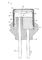
本発明では、各種の開始装置の構成が使用可能であり、又は使用のために適切に変更可能である。図からわかるように、本発明に基づく開始装置10の好適な実施例は、パイロテクニック開始装置に通常みられる多数の特徴を含む。例えば、モールド絶縁体55があり、また絶縁カップ56で囲まれた容器65に密閉状に取付けられた密着された同軸ヘッダアセンブリ20がある。次に前述の同軸ヘッダアセンブリ20は、同軸で孤立した(isolated)センターピン40、ガラス50、アイレット60、溶接されたブリッジワイヤ70、及びグランドピン30から構成されており、両ピン30及び40はモールド絶縁体55を越えて伸び、コネクタ末端を形成している。
【0005】
しかしながら、本発明の前述の実施例では、好ましくは均一に円筒状であるスリーブ90の下部位を、スリーブ90のおよそ上半分又は3分の1がヘッダアセンブリ20の上面に残ったままになるまで、アイレット60上に滑らせる。その後、スリーブ90の下端部92を、対応するアイレット60の円周方向のくぼみに沿わせて内側に折り曲げる(crimp)ことで、スリーブ90をアイレット60にしっかり固定することが可能となる。その他の溶接等の適当な方法も、該スリーブを固定するのに使用可能である。
【0006】
それに続いて、好ましくは実質的に全てのスリーブ90内の開口部(即ち、ヘッダアセンブリ20の上面に残っている前記上半分又は3分の1内の開口部)に、適切なパイロテクニック火薬82を装填する。好ましくは、これは、スラリー装填技術、又は当該技術分野に公知の類似の手法を使用して行われる。当該スラリー装填可能なパイロテクニック組成例のいくつかは、米国特許番号5,686,691(Hamilton他)に記載されており、その開示内容は、完全に記載されるかのように、本明細書に参考として盛り込まれている。好ましくは、スラリーの乾燥後に(好ましさは下回るが、乾燥前又は乾燥中になされてもよいが)、スリーブ90の上端部91を円周方向に内側に折り曲げると、上端部91が狭くなり火薬82を押し込むことになる。この工程中又は工程後に、火薬82をより密に詰め込み、ブリッジワイヤ70によりしっかり押付けるために、好ましくは(必須ではないが)火薬82の上部を下側に押付ける。押付けにより、火薬82の上部が平らに又はスリーブ90の上部が凸状に突出して形成される可能性があるが、好ましくは、(図に示すような)火薬82上に凹面が生成する。
【0007】
スリーブ90は、好ましくは、前述のようにヘッダアセンブリ20に取付けられた後に装着されるが、代わりにスリーブ90は単独で火薬82を先に装填(好ましくは、スラリーを、また好ましくは平坦面上で又は適切な備品上で上下逆にして装填)されてよい(よって、スリーブ90上部位の所望の部分を充填することが可能である)。その後(好ましくは、スラリーの乾燥後)、火薬82の底部がブリッジワイヤ70と密に接触するように、ヘッダアセンブリ20の上部をスリーブ90に挿入可能である。その後、前述のように、スリーブ90の下端部92をアイレット60にしっかりつけ、スリーブ90の上端部91を内側に折り曲げる。
【0008】
或いは、スリーブ90における狭められた上端部91を、スリーブ90の装着後にそれを折り曲げることで形成するよりも、スリーブ90を、スリーブを折り曲げる必要なしに、最初から狭められた端部と、スリーブ内で装填され乾燥可能なスラリー火薬とを有して形成可能である。しかしながら、これは、スリーブ内でスラリーが乾燥した後に狭められた端部を形成するよりも、好ましさは下回る。
【0009】
いずれにせよ、一旦スラリーが乾燥すれば、結果として生じるパイロテクニック火薬82は物理的にスリーブ90により所定の位置に保持される。具体的には、狭められた上端部91(これは、狭められた上端部91の下にある火薬82の外径よりも小さい内径を有する)の閉塞、並びに火薬82とスリーブ90の壁面との間の結合及び/又は摩擦が、火薬82をブリッジワイヤ70(或いは、その他の適切な電気的開始要素(electrical initiating element))と密に接触させたままにする。よって、パイロテクニック火薬82をヘッダアセンブリ20に組み合わせてブリッジワイヤ70と密に接触させる工程は、単純化されるのに加えて、更に信頼性が高まる。
【0010】
実質的には、結果として生じる開始装置サブアセンブリ(ヘッダアセンブリ20及びパイロテクニック火薬82を装填したスリーブ90を含む)を、例えばスルーウェルド(through−weld)61を使用して、容器65に押し込み、密着させて取り付ける。容器65の内部は、図ではスリーブ90の上端部91に接していないように描かれているが、容器65の内部は、必要であれば、代わってスリーブ90の上端部91に接触していてもよい。開始装置10を完成させるために、適切な絶縁カップ56及び絶縁体55が、当該技術分野で公知のように、設けられる。
【0011】
以上、パイロテクニック火薬を保持する、狭められたスリーブを有するパイロテクニック開始装置の好適な実施例、及びそれに付随する利点の多くを開示した。しかしながら、本発明の思想及び範囲から逸脱することなく、構成要素の形態、構成及び配置において各種の変更が可能であり、また上述の形態とは、単に好適な又は典型的な実施例であることは明白であろう。従って、本発明は、次の特許請求の範囲に基づく場合を除いて、制限又は限定されるべきではない。
【図面の簡単な説明】
【0012】
【図1】本発明の実施例における断面図である。
【符号の説明】
【0013】
10 開始装置
20 ヘッダアセンブリ
30 グランドピン
40 センターピン
50 ガラス
55 モールド絶縁体
56 絶縁カップ
60 アイレット
65 容器
70 ブリッジワイヤ
82 パイロテクニック火薬
90 スリーブ
91 上端部
92 下端部【Technical field】
[0001]
The present invention relates to the field of pyrotechnic initiators, and more particularly to a pyrotechnic initiator having a folded sleeve for holding a pyrotechnic charge.
[Background Art]
[0002]
Pyrotechnic initiators have many uses in industrial and consumer applications. One of the important applications is in inducing airbag inflation in automobiles. Significant efforts have been made in the automotive industry to reduce the cost of manufacturing reliable airbag initiators. One advance has been the use of liquids and slurries when loading pyrotechnic explosives into the initiator. Although there remains a great need to further reduce the cost of manufacturing reliable starters, heretofore, a narrowed sleeve has been used to hold the pyrotechnic powder in the starter. I've never had one.
DISCLOSURE OF THE INVENTION
[Means for Solving the Problems]
[0003]
According to the invention, a sleeve with a narrowed end holds the pyrotechnic powder in place on the initiator.
BEST MODE FOR CARRYING OUT THE INVENTION
[0004]
In the present invention, various initiator arrangements can be used or suitably modified for use. As can be seen, the preferred embodiment of the
[0005]
However, in the foregoing embodiment of the invention, the lower portion of the
[0006]
Subsequently, preferably, substantially all of the openings in the sleeve 90 (i.e., the openings in the upper half or third remaining on the top surface of the header assembly 20) are provided with a suitable
[0007]
The
[0008]
Alternatively, rather than forming the narrowed
[0009]
In any event, once the slurry has dried, the resulting
[0010]
In effect, the resulting initiator sub-assembly (including the
[0011]
The foregoing has disclosed a preferred embodiment of a pyrotechnic initiator having a narrowed sleeve for holding a pyrotechnic explosive and many of the attendant advantages. However, various changes can be made in the form, configuration, and arrangement of the components without departing from the spirit and scope of the invention, and the above forms are merely preferred or typical embodiments. Will be obvious. Accordingly, the invention is not to be restricted or limited except as by the following claims.
[Brief description of the drawings]
[0012]
FIG. 1 is a sectional view of an embodiment of the present invention.
[Explanation of symbols]
[0013]
10
Claims (20)
開始要素とを含むヘッダアセンブリと、
b)前記アイレットに取付けられ、前記アイレットの上面の上側に突出しており、狭められた上端部を有するスリーブと、
c)前記スリーブ内にあって、前記スリーブにおける狭められた上端部の内径よりも大きい最大外径を有し、前記スリーブ及び前記露出した電気的開始要素にしっかり接触しているパイロテクニック火薬と、
を備えることを特徴とするパイロテクニック開始装置サブアセンブリ。a) a header assembly including an eyelet, a top surface, and an electrical starting element exposed on the top surface;
b) a sleeve attached to the eyelet, projecting above an upper surface of the eyelet, and having a narrowed upper end;
c) a pyrotechnic explosive within the sleeve, having a maximum outer diameter greater than the inner diameter of the narrowed upper end of the sleeve, and in firm contact with the sleeve and the exposed electrical starting element;
A pyrotechnic initiator subassembly comprising:
b)上部位、及び前記アイレットの外径とほぼ同じ内径を持つ下部位を有するスリーブを備える工程と、
c)前記スリーブの下部位を前記アイレット上に配置し、前記スリーブを前記アイレットにしっかり取付ける工程と、
d)前記スリーブの上部位に液体又はスラリー状パイロテクニック火薬を装填する工程と、
e)前記液体又はスラリー状パイロテクニック火薬を乾燥する工程と、
f)前記スリーブの上部位に、狭められた上端部を備える工程と、
を備えることを特徴とするパイロテクニック開始装置サブアセンブリの作成方法。a) providing a header assembly including an upper surface, an eyelet having an outer diameter, and an electrical starting element exposed on the upper surface;
b) providing a sleeve having an upper portion and a lower portion having an inner diameter substantially the same as the outer diameter of the eyelet;
c) placing a lower portion of the sleeve over the eyelet and securely attaching the sleeve to the eyelet;
d) loading a pyrotechnic powder in liquid or slurry form on the upper portion of the sleeve;
e) drying the liquid or slurry pyrotechnic explosive;
f) providing a narrowed upper end at the upper portion of the sleeve;
A method for creating a pyrotechnic initiator subassembly, comprising:
Applications Claiming Priority (2)
| Application Number | Priority Date | Filing Date | Title |
|---|---|---|---|
| US09/733,755 US6578487B2 (en) | 2000-12-08 | 2000-12-08 | Pyrotechnic initiator with a narrowed sleeve retaining a pyrotechnic charge and methods of making same |
| PCT/US2001/044197 WO2002046688A1 (en) | 2000-12-08 | 2001-11-21 | Pyrotechnic initiator with a narrowed sleeve and methods of making same |
Publications (2)
| Publication Number | Publication Date |
|---|---|
| JP2004525329A true JP2004525329A (en) | 2004-08-19 |
| JP2004525329A5 JP2004525329A5 (en) | 2005-05-26 |
Family
ID=24948987
Family Applications (1)
| Application Number | Title | Priority Date | Filing Date |
|---|---|---|---|
| JP2002548381A Pending JP2004525329A (en) | 2000-12-08 | 2001-11-21 | Pyrotechnic starter with narrowed sleeve and method of making same |
Country Status (5)
| Country | Link |
|---|---|
| US (1) | US6578487B2 (en) |
| EP (1) | EP1340038A1 (en) |
| JP (1) | JP2004525329A (en) |
| AU (1) | AU2002226973A1 (en) |
| WO (1) | WO2002046688A1 (en) |
Cited By (1)
| Publication number | Priority date | Publication date | Assignee | Title |
|---|---|---|---|---|
| US7789984B2 (en) | 2005-12-19 | 2010-09-07 | Daicel Chemical Industries, Ltd. | Method for supplying pyrotechnic material slurry |
Families Citing this family (20)
| Publication number | Priority date | Publication date | Assignee | Title |
|---|---|---|---|---|
| US6848365B2 (en) * | 2000-12-08 | 2005-02-01 | Special Devices, Inc. | Initiator with an internal sleeve retaining a pyrotechnic charge and methods of making same |
| JP4021178B2 (en) * | 2001-11-21 | 2007-12-12 | ダイセル化学工業株式会社 | Initiator assembly |
| JP3906910B2 (en) * | 2002-03-29 | 2007-04-18 | トヨタ自動車株式会社 | initiator |
| US20030192446A1 (en) * | 2002-04-16 | 2003-10-16 | Paul Berg | Header with overlying eyelet |
| US20040000248A1 (en) * | 2002-07-01 | 2004-01-01 | Vahan Avetisian | Initiator with a bridgewire in contact with slurry-loaded pyrotechnic charge at a position of relatively low void formation |
| US6779456B2 (en) * | 2002-07-01 | 2004-08-24 | Special Devices, Inc. | Initiator with a bridgewire configured in an enhanced heat-sinking relationship |
| US6698356B2 (en) * | 2002-07-01 | 2004-03-02 | Special Devices, Incorporated | Axial spin method of distributing pyrotechnic charge in an initiator |
| US6976430B2 (en) * | 2002-09-02 | 2005-12-20 | Daicel Chemical Industries, Ltd. | Igniter for inflator and method of manufacturing thereof |
| US6907827B2 (en) * | 2002-11-14 | 2005-06-21 | Special Devices, Inc. | Pyrotechnic initiator having output can with encapsulation material retention feature |
| DE20307603U1 (en) * | 2003-05-15 | 2003-09-25 | Trw Airbag Sys Gmbh | Lighter for use in a vehicle occupant protection device |
| JP2005069666A (en) * | 2003-08-06 | 2005-03-17 | Takata Corp | Initiator and gas generator |
| US6905562B2 (en) * | 2003-09-04 | 2005-06-14 | Autoliv Asp, Inc. | Low density slurry bridge mix |
| US20060017269A1 (en) * | 2004-07-26 | 2006-01-26 | Daicel Chemical Industries, Ltd. | Igniter assembly |
| JP2007170687A (en) * | 2005-12-19 | 2007-07-05 | Daicel Chem Ind Ltd | Method of supplying pyrotechnic material slurry |
| EP2157399A4 (en) * | 2007-06-13 | 2013-03-20 | Nippon Kayaku Kk | Squib, gas generation device for airbag, and gas generation device for seatbelt pretensioner |
| JP5897417B2 (en) * | 2012-07-13 | 2016-03-30 | 株式会社ダイセル | Cover member for igniter |
| GB2537414B (en) * | 2015-04-17 | 2019-11-13 | Graviner Ltd Kidde | Pyrotechnic valve |
| DE102019123755A1 (en) * | 2019-09-05 | 2021-03-11 | Auto-Kabel Management Gmbh | Pyrotechnic squib and method for producing a pyrotechnic squib |
| EP4015979A1 (en) * | 2019-12-19 | 2022-06-22 | Schott Ag | Metal fixing material feedthrough, method for the production and uses thereof |
| US11718267B1 (en) | 2022-03-18 | 2023-08-08 | Autoliv Asp, Inc. | Initiator for a gas generator of a vehicle safety device |
Family Cites Families (16)
| Publication number | Priority date | Publication date | Assignee | Title |
|---|---|---|---|---|
| US2400103A (en) * | 1941-04-16 | 1946-05-14 | William M Cobb | Detonator or blasting cap |
| US2393629A (en) * | 1941-07-03 | 1946-01-29 | Specialties Dev Corp | Explosive cartridge |
| GB927705A (en) * | 1960-09-20 | 1963-06-06 | Graviner Manufacturing Co | Improvements in or relating to explosive charges |
| US3128703A (en) * | 1961-05-23 | 1964-04-14 | Du Pont | Water impervious detonator |
| US3306202A (en) * | 1964-12-02 | 1967-02-28 | Vincent J Menichelli | Electric initiator |
| US5140906A (en) * | 1991-11-05 | 1992-08-25 | Ici Americas, Inc. | Airbag igniter having double glass seal |
| DE4307774A1 (en) * | 1993-03-12 | 1994-09-15 | Dynamit Nobel Ag | Ignition device |
| US5728964A (en) * | 1993-10-20 | 1998-03-17 | Quantic Industries, Inc. | Electrical initiator |
| FR2720493B1 (en) * | 1994-05-31 | 1996-07-19 | Giat Ind Sa | Pyrotechnic initiator. |
| US5538278A (en) * | 1994-06-14 | 1996-07-23 | Ad Astram Enterprises, Inc. | Ignition train apparatus for hybrid airbag inflators |
| US5621183A (en) * | 1995-01-12 | 1997-04-15 | Trw Inc. | Initiator for an air bag inflator |
| US5686691A (en) | 1995-12-22 | 1997-11-11 | Oea, Inc. | Slurry-loadable electrical initiator |
| US5932832A (en) * | 1996-04-15 | 1999-08-03 | Autoliv Asp, Inc. | High pressure resistant initiator with integral metal oxide varistor for electro-static discharge protection |
| US5988069A (en) * | 1996-11-12 | 1999-11-23 | Universal Propulsion Company, Inc. | Electric initiator having a sealing material forming a ceramic to metal seal |
| US6295935B1 (en) * | 1998-04-27 | 2001-10-02 | Trw Inc. | Initiator for air bag inflator |
| FR2788846B1 (en) * | 1999-01-25 | 2001-10-26 | Livbag Snc | HYBRID GAS GENERATOR WITH PROFILE EXPLOSIVE LOADING INITIATOR |
-
2000
- 2000-12-08 US US09/733,755 patent/US6578487B2/en not_active Expired - Lifetime
-
2001
- 2001-11-21 EP EP01995925A patent/EP1340038A1/en not_active Withdrawn
- 2001-11-21 WO PCT/US2001/044197 patent/WO2002046688A1/en not_active Application Discontinuation
- 2001-11-21 JP JP2002548381A patent/JP2004525329A/en active Pending
- 2001-11-21 AU AU2002226973A patent/AU2002226973A1/en not_active Abandoned
Cited By (1)
| Publication number | Priority date | Publication date | Assignee | Title |
|---|---|---|---|---|
| US7789984B2 (en) | 2005-12-19 | 2010-09-07 | Daicel Chemical Industries, Ltd. | Method for supplying pyrotechnic material slurry |
Also Published As
| Publication number | Publication date |
|---|---|
| US6578487B2 (en) | 2003-06-17 |
| US20020069782A1 (en) | 2002-06-13 |
| WO2002046688A1 (en) | 2002-06-13 |
| AU2002226973A1 (en) | 2002-06-18 |
| EP1340038A1 (en) | 2003-09-03 |
Similar Documents
| Publication | Publication Date | Title |
|---|---|---|
| JP2004525329A (en) | Pyrotechnic starter with narrowed sleeve and method of making same | |
| JP2004525329A5 (en) | ||
| JP4435321B2 (en) | Explosive device assembly and manufacturing method thereof | |
| US6848365B2 (en) | Initiator with an internal sleeve retaining a pyrotechnic charge and methods of making same | |
| JP2002508503A (en) | Bridge wire starter | |
| CN101305258B (en) | A glass-metal connector, a method of fabricating it, and an electro-pyrotechnic initiator including it | |
| US20090044715A1 (en) | Metal/fixing-means base or socket for ignition devices for airbags or similar personal safety systems, in particular in motor vehicles and ignition device with such a base | |
| US6612241B2 (en) | Pyrotechnic initiator with center pin having a circumferential notch retention feature | |
| JP2006278336A (en) | Electric connector jack | |
| JP7258036B2 (en) | Ignition device for gas generator and method for manufacturing the ignition device | |
| JP2005502014A (en) | Overmolded body for pyrotechnic starting device and method for producing the same | |
| US4813893A (en) | Electrical terminal and method of assembly | |
| JP2004535547A5 (en) | ||
| EP0550052B1 (en) | Lamp capsule support base | |
| JP2005531743A (en) | Initiator with a sliding surface between the ignition agent and the output agent | |
| US5677596A (en) | Plug with radiation screening element | |
| JP2005531741A (en) | Initiator with bridge wires arranged in a reinforced endothermic relationship | |
| US6698356B2 (en) | Axial spin method of distributing pyrotechnic charge in an initiator | |
| US20030221578A1 (en) | Detonator with onboard electronics mechanically connected to ignition element | |
| US20030221575A1 (en) | Detonator utilizing features of automotive airbag initiators | |
| EP2078326B1 (en) | Reversible lamp base | |
| JP2005531742A (en) | Initiator with bridge wire in contact with slurry-containing pyrotechnic agent at relatively low void formation | |
| JP2005297631A (en) | Igniting device | |
| JP2002313471A (en) | Probe pin | |
| JPS649344U (en) |
Legal Events
| Date | Code | Title | Description |
|---|---|---|---|
| A621 | Written request for application examination |
Free format text: JAPANESE INTERMEDIATE CODE: A621 Effective date: 20041119 |
|
| A131 | Notification of reasons for refusal |
Free format text: JAPANESE INTERMEDIATE CODE: A131 Effective date: 20070130 |
|
| A02 | Decision of refusal |
Free format text: JAPANESE INTERMEDIATE CODE: A02 Effective date: 20070626 |