JP2004522983A - How to use high brightness partially transmissive LCD and tunable mirror - Google Patents
How to use high brightness partially transmissive LCD and tunable mirror Download PDFInfo
- Publication number
- JP2004522983A JP2004522983A JP2002532996A JP2002532996A JP2004522983A JP 2004522983 A JP2004522983 A JP 2004522983A JP 2002532996 A JP2002532996 A JP 2002532996A JP 2002532996 A JP2002532996 A JP 2002532996A JP 2004522983 A JP2004522983 A JP 2004522983A
- Authority
- JP
- Japan
- Prior art keywords
- light
- liquid crystal
- crystal cell
- retarder
- state
- Prior art date
- Legal status (The legal status is an assumption and is not a legal conclusion. Google has not performed a legal analysis and makes no representation as to the accuracy of the status listed.)
- Pending
Links
Images


Classifications
-
- G—PHYSICS
- G02—OPTICS
- G02F—OPTICAL DEVICES OR ARRANGEMENTS FOR THE CONTROL OF LIGHT BY MODIFICATION OF THE OPTICAL PROPERTIES OF THE MEDIA OF THE ELEMENTS INVOLVED THEREIN; NON-LINEAR OPTICS; FREQUENCY-CHANGING OF LIGHT; OPTICAL LOGIC ELEMENTS; OPTICAL ANALOGUE/DIGITAL CONVERTERS
- G02F1/00—Devices or arrangements for the control of the intensity, colour, phase, polarisation or direction of light arriving from an independent light source, e.g. switching, gating or modulating; Non-linear optics
- G02F1/01—Devices or arrangements for the control of the intensity, colour, phase, polarisation or direction of light arriving from an independent light source, e.g. switching, gating or modulating; Non-linear optics for the control of the intensity, phase, polarisation or colour
- G02F1/13—Devices or arrangements for the control of the intensity, colour, phase, polarisation or direction of light arriving from an independent light source, e.g. switching, gating or modulating; Non-linear optics for the control of the intensity, phase, polarisation or colour based on liquid crystals, e.g. single liquid crystal display cells
- G02F1/133—Constructional arrangements; Operation of liquid crystal cells; Circuit arrangements
- G02F1/1333—Constructional arrangements; Manufacturing methods
- G02F1/1335—Structural association of cells with optical devices, e.g. polarisers or reflectors
- G02F1/133553—Reflecting elements
-
- G—PHYSICS
- G02—OPTICS
- G02F—OPTICAL DEVICES OR ARRANGEMENTS FOR THE CONTROL OF LIGHT BY MODIFICATION OF THE OPTICAL PROPERTIES OF THE MEDIA OF THE ELEMENTS INVOLVED THEREIN; NON-LINEAR OPTICS; FREQUENCY-CHANGING OF LIGHT; OPTICAL LOGIC ELEMENTS; OPTICAL ANALOGUE/DIGITAL CONVERTERS
- G02F1/00—Devices or arrangements for the control of the intensity, colour, phase, polarisation or direction of light arriving from an independent light source, e.g. switching, gating or modulating; Non-linear optics
- G02F1/01—Devices or arrangements for the control of the intensity, colour, phase, polarisation or direction of light arriving from an independent light source, e.g. switching, gating or modulating; Non-linear optics for the control of the intensity, phase, polarisation or colour
- G02F1/13—Devices or arrangements for the control of the intensity, colour, phase, polarisation or direction of light arriving from an independent light source, e.g. switching, gating or modulating; Non-linear optics for the control of the intensity, phase, polarisation or colour based on liquid crystals, e.g. single liquid crystal display cells
- G02F1/133—Constructional arrangements; Operation of liquid crystal cells; Circuit arrangements
- G02F1/1333—Constructional arrangements; Manufacturing methods
- G02F1/1347—Arrangement of liquid crystal layers or cells in which the final condition of one light beam is achieved by the addition of the effects of two or more layers or cells
-
- G—PHYSICS
- G02—OPTICS
- G02F—OPTICAL DEVICES OR ARRANGEMENTS FOR THE CONTROL OF LIGHT BY MODIFICATION OF THE OPTICAL PROPERTIES OF THE MEDIA OF THE ELEMENTS INVOLVED THEREIN; NON-LINEAR OPTICS; FREQUENCY-CHANGING OF LIGHT; OPTICAL LOGIC ELEMENTS; OPTICAL ANALOGUE/DIGITAL CONVERTERS
- G02F1/00—Devices or arrangements for the control of the intensity, colour, phase, polarisation or direction of light arriving from an independent light source, e.g. switching, gating or modulating; Non-linear optics
- G02F1/01—Devices or arrangements for the control of the intensity, colour, phase, polarisation or direction of light arriving from an independent light source, e.g. switching, gating or modulating; Non-linear optics for the control of the intensity, phase, polarisation or colour
- G02F1/13—Devices or arrangements for the control of the intensity, colour, phase, polarisation or direction of light arriving from an independent light source, e.g. switching, gating or modulating; Non-linear optics for the control of the intensity, phase, polarisation or colour based on liquid crystals, e.g. single liquid crystal display cells
- G02F1/133—Constructional arrangements; Operation of liquid crystal cells; Circuit arrangements
- G02F1/1333—Constructional arrangements; Manufacturing methods
- G02F1/1335—Structural association of cells with optical devices, e.g. polarisers or reflectors
- G02F1/133504—Diffusing, scattering, diffracting elements
-
- G—PHYSICS
- G02—OPTICS
- G02F—OPTICAL DEVICES OR ARRANGEMENTS FOR THE CONTROL OF LIGHT BY MODIFICATION OF THE OPTICAL PROPERTIES OF THE MEDIA OF THE ELEMENTS INVOLVED THEREIN; NON-LINEAR OPTICS; FREQUENCY-CHANGING OF LIGHT; OPTICAL LOGIC ELEMENTS; OPTICAL ANALOGUE/DIGITAL CONVERTERS
- G02F1/00—Devices or arrangements for the control of the intensity, colour, phase, polarisation or direction of light arriving from an independent light source, e.g. switching, gating or modulating; Non-linear optics
- G02F1/01—Devices or arrangements for the control of the intensity, colour, phase, polarisation or direction of light arriving from an independent light source, e.g. switching, gating or modulating; Non-linear optics for the control of the intensity, phase, polarisation or colour
- G02F1/13—Devices or arrangements for the control of the intensity, colour, phase, polarisation or direction of light arriving from an independent light source, e.g. switching, gating or modulating; Non-linear optics for the control of the intensity, phase, polarisation or colour based on liquid crystals, e.g. single liquid crystal display cells
- G02F1/133—Constructional arrangements; Operation of liquid crystal cells; Circuit arrangements
- G02F1/1333—Constructional arrangements; Manufacturing methods
- G02F1/1335—Structural association of cells with optical devices, e.g. polarisers or reflectors
- G02F1/133528—Polarisers
- G02F1/133536—Reflective polarizers
-
- G—PHYSICS
- G02—OPTICS
- G02F—OPTICAL DEVICES OR ARRANGEMENTS FOR THE CONTROL OF LIGHT BY MODIFICATION OF THE OPTICAL PROPERTIES OF THE MEDIA OF THE ELEMENTS INVOLVED THEREIN; NON-LINEAR OPTICS; FREQUENCY-CHANGING OF LIGHT; OPTICAL LOGIC ELEMENTS; OPTICAL ANALOGUE/DIGITAL CONVERTERS
- G02F1/00—Devices or arrangements for the control of the intensity, colour, phase, polarisation or direction of light arriving from an independent light source, e.g. switching, gating or modulating; Non-linear optics
- G02F1/01—Devices or arrangements for the control of the intensity, colour, phase, polarisation or direction of light arriving from an independent light source, e.g. switching, gating or modulating; Non-linear optics for the control of the intensity, phase, polarisation or colour
- G02F1/13—Devices or arrangements for the control of the intensity, colour, phase, polarisation or direction of light arriving from an independent light source, e.g. switching, gating or modulating; Non-linear optics for the control of the intensity, phase, polarisation or colour based on liquid crystals, e.g. single liquid crystal display cells
- G02F1/133—Constructional arrangements; Operation of liquid crystal cells; Circuit arrangements
- G02F1/1333—Constructional arrangements; Manufacturing methods
- G02F1/1335—Structural association of cells with optical devices, e.g. polarisers or reflectors
- G02F1/133528—Polarisers
- G02F1/133543—Cholesteric polarisers
-
- G—PHYSICS
- G02—OPTICS
- G02F—OPTICAL DEVICES OR ARRANGEMENTS FOR THE CONTROL OF LIGHT BY MODIFICATION OF THE OPTICAL PROPERTIES OF THE MEDIA OF THE ELEMENTS INVOLVED THEREIN; NON-LINEAR OPTICS; FREQUENCY-CHANGING OF LIGHT; OPTICAL LOGIC ELEMENTS; OPTICAL ANALOGUE/DIGITAL CONVERTERS
- G02F1/00—Devices or arrangements for the control of the intensity, colour, phase, polarisation or direction of light arriving from an independent light source, e.g. switching, gating or modulating; Non-linear optics
- G02F1/01—Devices or arrangements for the control of the intensity, colour, phase, polarisation or direction of light arriving from an independent light source, e.g. switching, gating or modulating; Non-linear optics for the control of the intensity, phase, polarisation or colour
- G02F1/13—Devices or arrangements for the control of the intensity, colour, phase, polarisation or direction of light arriving from an independent light source, e.g. switching, gating or modulating; Non-linear optics for the control of the intensity, phase, polarisation or colour based on liquid crystals, e.g. single liquid crystal display cells
- G02F1/133—Constructional arrangements; Operation of liquid crystal cells; Circuit arrangements
- G02F1/1333—Constructional arrangements; Manufacturing methods
- G02F1/1335—Structural association of cells with optical devices, e.g. polarisers or reflectors
- G02F1/133553—Reflecting elements
- G02F1/133555—Transflectors
-
- G—PHYSICS
- G02—OPTICS
- G02F—OPTICAL DEVICES OR ARRANGEMENTS FOR THE CONTROL OF LIGHT BY MODIFICATION OF THE OPTICAL PROPERTIES OF THE MEDIA OF THE ELEMENTS INVOLVED THEREIN; NON-LINEAR OPTICS; FREQUENCY-CHANGING OF LIGHT; OPTICAL LOGIC ELEMENTS; OPTICAL ANALOGUE/DIGITAL CONVERTERS
- G02F1/00—Devices or arrangements for the control of the intensity, colour, phase, polarisation or direction of light arriving from an independent light source, e.g. switching, gating or modulating; Non-linear optics
- G02F1/01—Devices or arrangements for the control of the intensity, colour, phase, polarisation or direction of light arriving from an independent light source, e.g. switching, gating or modulating; Non-linear optics for the control of the intensity, phase, polarisation or colour
- G02F1/13—Devices or arrangements for the control of the intensity, colour, phase, polarisation or direction of light arriving from an independent light source, e.g. switching, gating or modulating; Non-linear optics for the control of the intensity, phase, polarisation or colour based on liquid crystals, e.g. single liquid crystal display cells
- G02F1/133—Constructional arrangements; Operation of liquid crystal cells; Circuit arrangements
- G02F1/1333—Constructional arrangements; Manufacturing methods
- G02F1/1335—Structural association of cells with optical devices, e.g. polarisers or reflectors
- G02F1/1336—Illuminating devices
- G02F1/133626—Illuminating devices providing two modes of illumination, e.g. day-night
-
- G—PHYSICS
- G02—OPTICS
- G02F—OPTICAL DEVICES OR ARRANGEMENTS FOR THE CONTROL OF LIGHT BY MODIFICATION OF THE OPTICAL PROPERTIES OF THE MEDIA OF THE ELEMENTS INVOLVED THEREIN; NON-LINEAR OPTICS; FREQUENCY-CHANGING OF LIGHT; OPTICAL LOGIC ELEMENTS; OPTICAL ANALOGUE/DIGITAL CONVERTERS
- G02F1/00—Devices or arrangements for the control of the intensity, colour, phase, polarisation or direction of light arriving from an independent light source, e.g. switching, gating or modulating; Non-linear optics
- G02F1/01—Devices or arrangements for the control of the intensity, colour, phase, polarisation or direction of light arriving from an independent light source, e.g. switching, gating or modulating; Non-linear optics for the control of the intensity, phase, polarisation or colour
- G02F1/13—Devices or arrangements for the control of the intensity, colour, phase, polarisation or direction of light arriving from an independent light source, e.g. switching, gating or modulating; Non-linear optics for the control of the intensity, phase, polarisation or colour based on liquid crystals, e.g. single liquid crystal display cells
- G02F1/137—Devices or arrangements for the control of the intensity, colour, phase, polarisation or direction of light arriving from an independent light source, e.g. switching, gating or modulating; Non-linear optics for the control of the intensity, phase, polarisation or colour based on liquid crystals, e.g. single liquid crystal display cells characterised by the electro-optical or magneto-optical effect, e.g. field-induced phase transition, orientation effect, guest-host interaction or dynamic scattering
- G02F1/13718—Devices or arrangements for the control of the intensity, colour, phase, polarisation or direction of light arriving from an independent light source, e.g. switching, gating or modulating; Non-linear optics for the control of the intensity, phase, polarisation or colour based on liquid crystals, e.g. single liquid crystal display cells characterised by the electro-optical or magneto-optical effect, e.g. field-induced phase transition, orientation effect, guest-host interaction or dynamic scattering based on a change of the texture state of a cholesteric liquid crystal
-
- G—PHYSICS
- G02—OPTICS
- G02F—OPTICAL DEVICES OR ARRANGEMENTS FOR THE CONTROL OF LIGHT BY MODIFICATION OF THE OPTICAL PROPERTIES OF THE MEDIA OF THE ELEMENTS INVOLVED THEREIN; NON-LINEAR OPTICS; FREQUENCY-CHANGING OF LIGHT; OPTICAL LOGIC ELEMENTS; OPTICAL ANALOGUE/DIGITAL CONVERTERS
- G02F1/00—Devices or arrangements for the control of the intensity, colour, phase, polarisation or direction of light arriving from an independent light source, e.g. switching, gating or modulating; Non-linear optics
- G02F1/01—Devices or arrangements for the control of the intensity, colour, phase, polarisation or direction of light arriving from an independent light source, e.g. switching, gating or modulating; Non-linear optics for the control of the intensity, phase, polarisation or colour
- G02F1/13—Devices or arrangements for the control of the intensity, colour, phase, polarisation or direction of light arriving from an independent light source, e.g. switching, gating or modulating; Non-linear optics for the control of the intensity, phase, polarisation or colour based on liquid crystals, e.g. single liquid crystal display cells
- G02F1/137—Devices or arrangements for the control of the intensity, colour, phase, polarisation or direction of light arriving from an independent light source, e.g. switching, gating or modulating; Non-linear optics for the control of the intensity, phase, polarisation or colour based on liquid crystals, e.g. single liquid crystal display cells characterised by the electro-optical or magneto-optical effect, e.g. field-induced phase transition, orientation effect, guest-host interaction or dynamic scattering
- G02F1/139—Devices or arrangements for the control of the intensity, colour, phase, polarisation or direction of light arriving from an independent light source, e.g. switching, gating or modulating; Non-linear optics for the control of the intensity, phase, polarisation or colour based on liquid crystals, e.g. single liquid crystal display cells characterised by the electro-optical or magneto-optical effect, e.g. field-induced phase transition, orientation effect, guest-host interaction or dynamic scattering based on orientation effects in which the liquid crystal remains transparent
- G02F1/1393—Devices or arrangements for the control of the intensity, colour, phase, polarisation or direction of light arriving from an independent light source, e.g. switching, gating or modulating; Non-linear optics for the control of the intensity, phase, polarisation or colour based on liquid crystals, e.g. single liquid crystal display cells characterised by the electro-optical or magneto-optical effect, e.g. field-induced phase transition, orientation effect, guest-host interaction or dynamic scattering based on orientation effects in which the liquid crystal remains transparent the birefringence of the liquid crystal being electrically controlled, e.g. ECB-, DAP-, HAN-, PI-LC cells
-
- G—PHYSICS
- G02—OPTICS
- G02F—OPTICAL DEVICES OR ARRANGEMENTS FOR THE CONTROL OF LIGHT BY MODIFICATION OF THE OPTICAL PROPERTIES OF THE MEDIA OF THE ELEMENTS INVOLVED THEREIN; NON-LINEAR OPTICS; FREQUENCY-CHANGING OF LIGHT; OPTICAL LOGIC ELEMENTS; OPTICAL ANALOGUE/DIGITAL CONVERTERS
- G02F1/00—Devices or arrangements for the control of the intensity, colour, phase, polarisation or direction of light arriving from an independent light source, e.g. switching, gating or modulating; Non-linear optics
- G02F1/01—Devices or arrangements for the control of the intensity, colour, phase, polarisation or direction of light arriving from an independent light source, e.g. switching, gating or modulating; Non-linear optics for the control of the intensity, phase, polarisation or colour
- G02F1/13—Devices or arrangements for the control of the intensity, colour, phase, polarisation or direction of light arriving from an independent light source, e.g. switching, gating or modulating; Non-linear optics for the control of the intensity, phase, polarisation or colour based on liquid crystals, e.g. single liquid crystal display cells
- G02F1/137—Devices or arrangements for the control of the intensity, colour, phase, polarisation or direction of light arriving from an independent light source, e.g. switching, gating or modulating; Non-linear optics for the control of the intensity, phase, polarisation or colour based on liquid crystals, e.g. single liquid crystal display cells characterised by the electro-optical or magneto-optical effect, e.g. field-induced phase transition, orientation effect, guest-host interaction or dynamic scattering
- G02F1/139—Devices or arrangements for the control of the intensity, colour, phase, polarisation or direction of light arriving from an independent light source, e.g. switching, gating or modulating; Non-linear optics for the control of the intensity, phase, polarisation or colour based on liquid crystals, e.g. single liquid crystal display cells characterised by the electro-optical or magneto-optical effect, e.g. field-induced phase transition, orientation effect, guest-host interaction or dynamic scattering based on orientation effects in which the liquid crystal remains transparent
- G02F1/141—Devices or arrangements for the control of the intensity, colour, phase, polarisation or direction of light arriving from an independent light source, e.g. switching, gating or modulating; Non-linear optics for the control of the intensity, phase, polarisation or colour based on liquid crystals, e.g. single liquid crystal display cells characterised by the electro-optical or magneto-optical effect, e.g. field-induced phase transition, orientation effect, guest-host interaction or dynamic scattering based on orientation effects in which the liquid crystal remains transparent using ferroelectric liquid crystals
-
- G—PHYSICS
- G02—OPTICS
- G02F—OPTICAL DEVICES OR ARRANGEMENTS FOR THE CONTROL OF LIGHT BY MODIFICATION OF THE OPTICAL PROPERTIES OF THE MEDIA OF THE ELEMENTS INVOLVED THEREIN; NON-LINEAR OPTICS; FREQUENCY-CHANGING OF LIGHT; OPTICAL LOGIC ELEMENTS; OPTICAL ANALOGUE/DIGITAL CONVERTERS
- G02F1/00—Devices or arrangements for the control of the intensity, colour, phase, polarisation or direction of light arriving from an independent light source, e.g. switching, gating or modulating; Non-linear optics
- G02F1/01—Devices or arrangements for the control of the intensity, colour, phase, polarisation or direction of light arriving from an independent light source, e.g. switching, gating or modulating; Non-linear optics for the control of the intensity, phase, polarisation or colour
- G02F1/15—Devices or arrangements for the control of the intensity, colour, phase, polarisation or direction of light arriving from an independent light source, e.g. switching, gating or modulating; Non-linear optics for the control of the intensity, phase, polarisation or colour based on an electrochromic effect
- G02F1/1506—Devices or arrangements for the control of the intensity, colour, phase, polarisation or direction of light arriving from an independent light source, e.g. switching, gating or modulating; Non-linear optics for the control of the intensity, phase, polarisation or colour based on an electrochromic effect caused by electrodeposition, e.g. electrolytic deposition of an inorganic material on or close to an electrode
-
- G—PHYSICS
- G02—OPTICS
- G02F—OPTICAL DEVICES OR ARRANGEMENTS FOR THE CONTROL OF LIGHT BY MODIFICATION OF THE OPTICAL PROPERTIES OF THE MEDIA OF THE ELEMENTS INVOLVED THEREIN; NON-LINEAR OPTICS; FREQUENCY-CHANGING OF LIGHT; OPTICAL LOGIC ELEMENTS; OPTICAL ANALOGUE/DIGITAL CONVERTERS
- G02F2203/00—Function characteristic
- G02F2203/02—Function characteristic reflective
-
- G—PHYSICS
- G02—OPTICS
- G02F—OPTICAL DEVICES OR ARRANGEMENTS FOR THE CONTROL OF LIGHT BY MODIFICATION OF THE OPTICAL PROPERTIES OF THE MEDIA OF THE ELEMENTS INVOLVED THEREIN; NON-LINEAR OPTICS; FREQUENCY-CHANGING OF LIGHT; OPTICAL LOGIC ELEMENTS; OPTICAL ANALOGUE/DIGITAL CONVERTERS
- G02F2203/00—Function characteristic
- G02F2203/09—Function characteristic transflective
Abstract
液晶ディスプレイ(LCD)は部分反射ミラーの代わりにチューナブルミラーを使用する。チューナブルミラーは、制御可能な反射率と透過率を有するので、LCDが反射モードで動作しているときにはミラーは主に光を反射し、LCDが透過モードで動作しているときにはミラーは主にバックライトからの光を透過させる。Liquid crystal displays (LCDs) use tunable mirrors instead of partially reflecting mirrors. Since the tunable mirror has a controllable reflectance and transmittance, the mirror mainly reflects light when the LCD is operating in the reflection mode, and the mirror mainly reflects light when the LCD is operating in the transmission mode. Transmits light from the backlight.
Description
【0001】
【発明の属する技術分野】
本発明は、液晶ディスプレイ(LCD)に関し、特に電池消費が少なくコントラストが高い半透過型LCDに関する。
【0002】
【従来の技術】
従来の半透過型LCDは、スクリーンから受光した周囲光をLCDを通して反射して戻し、周囲照明が弱いときに作動するバックライト発光を透過する半反射・半透過ミラー要素(半透過板としても知られている)を有する。
【0003】
従来の半透過型LCDでは、部分反射・部分透過ミラーにより、光の反射と透過が同時に行われるので、光の使用が非効率的である。さらに、透過率と反射率が固定値である。任意の時点で、ミラーの透過率と反射率の和は100%を超えることはあり得ないため、部分反射・部分透過ミラーは、反射板と透過板として同時に動作することで効率を犠牲にしている。通常そのようなミラーは70〜90%の反射率と10〜30%の透過率を有する。
【0004】
そのような非効率を補償するために、周囲光が弱い場合の透過モードでの動作時にはより多くの電池電力を使用してバックライト発光を増加させなければならない。同様に、周囲光が強い反射モードでの動作時にはコントラストが失われる。
【0005】
【発明の概要】
本発明は、部分反射・部分透過ミラーをチューナブルミラーに置き換えることで従来の部分透過型LCDの効率を改善するシステムと方法を提供する。チューナブルミラーは、透過率と反射率の程度が制御可能な任意の素子である。
【0006】
チューナブルミラーを使用する利点は、反射モードと透過モードとを切り替え、周囲照明が強いときには主に光を反射し、周囲照明が弱く背面照明が必要なときには主に光を透過することが可能なことである。これにより、LCDの透過モードでの動作時に必要な背面照明の量を減少して電池の寿命が節約され、反射モードでの動作時にコントラストと輝度が増加する。
【0007】
反転可能電気化学ミラー(REM)は、本発明に使用するのに適した種類のチューナブルミラーである。さらに、チューナブルミラーは、そのうちの少なくとも1つが電気的に切り替え可能な光学的性質を有する複数の光学要素から構築可能である。
【0008】
チューナブルミラーの1つの適切な構造は、4分の1波(λ/4)リターダを有するコレステリック液晶リフレクタを備える。この組み合わせでは、液晶リフレクタは、反射状態と透過状態との間で動作を切り替えて、ミラーに調整可能な性質を持たせることが可能である。
【0009】
チューナブルミラーの別の適切な構造は、ゼロ−半波(0−λ/2)チューナブル液晶リターダを有する反射偏光子を備える。そのようなリターダは、λ/2と0λとの状態の間で動作を切り替え、ミラーに調整可能な性質を持たせることが可能である。
【0010】
チューナブルミラーの第3の適切な構造は、負4分の1波〜正4分の1波(+/−λ/4)チューナブルリターダを有するコレステリックリフレクタを備える。そのようなリターダは、+λ/4と−λ/4との状態の間で動作を切り替え、ミラーに調整可能な性質を持たせることが可能である。
【0011】
ミラーとバックライトについてはさまざまな制御が可能である。たとえば、バックライトがオンに切り替えられたときにミラーが透過状態に設定されるように、ミラーとバックライトを直列に動作させるミラー制御システムとバックライト制御システムが採用可能である。ミラーとバックライトの制御を周囲光のレベルに自動的に対応するように設定することも可能である。
【0012】
【発明の実施の態様】
本発明は、従来技術の部分透過型LCDで使用される部分反射・部分透過ミラーをチューナブルミラーに置き換える。部分透過型LCDを作成するには、多くの方法がある。特定の種類のLCDを図に示すが、本発明は、部分反射・部分透過ミラーをチューナブルミラーで置き換え可能な、任意の部分透過型LCDに一般的に適用可能である。
【0013】
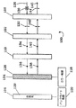
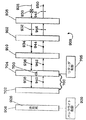
図1と図2は、それぞれ反射モードと透過モードで動作している本発明のLCD100を示している図である。
LCD100は液晶セル102、そのセルの背面のチューナブルミラー104、チューナブルミラー104の背面に設置されたバックライト106、セル102の前面の第1の偏光子108、セル102とチューナブルミラー104との間の第2の偏光子110、チューナブルミラー104用の制御部118、およびバックライト108用の制御部120を含む。
【0014】
液晶セル102は、超ねじれネマチック(STN)セル、アクティブマトリックスねじれネマチック(TN)セルであっても、パッシブTNセルであってもよい。液晶セルの構造は、通常、区画に分割された一対の電極間に挟まれた液晶層を含む。
【0015】
動作のノーマリホワイトモードでは、セル102は、オン(発光)状態またはオフ状態のいずれかで、オフ状態では電圧がセルの電極間に印加され、オン状態では電圧はセルの両端に印加されない。第1と第2の偏光子108と110の向きは、セルがオン状態のときには、一方の偏光子を通して入射した光がセルを通した透過時に、偏光方向が他方の偏光子の透過軸にほぼ平行になるように回転し、その偏光子から出射するように設定されている。セルがオフ状態のときには、一方の偏光子を通して入射する光は、セルによって回転し、偏光方向が他方の偏光子の透過軸に対してほぼ直交し、そのため光はその偏光子により遮断または吸収される。オン状態でセルが光を90°回転させるノーマリホワイトモードで動作する90°TNセルの例では、偏光子は、相互に直交する偏光面を有する。
【0016】
STNセルでは、偏光面は直交しないこともある。ノーマリブラックモードも使用可能で、その場合、オン状態で電圧が印加され、オフ状態では電圧は印加されない。ノーマリブラックモードで動作する90°TNセルの例では、偏光子は平行である(TNセルについての参照情報については、T.J. Scheffer, J. Nehring, ”Supertwisted Nematic LCDS”, Society for Information Display Seminar Lecture Notes, Vol. 1, M−12, May 15, 2000とその中の参考文献を参照されたい)。
【0017】
チューナブルミラー104は、それぞれ主に光を反射するか主に光を透過する反射モードと透過モードとの間で切り替え可能である。チューナブルミラーのより詳細な例を以下で説明する。
【0018】
バックライト106は、発光状態と非発光状態との間で動作を切り替え可能で、反対側から液晶セルに入射する周囲光が暗過ぎ、そのため目視可能しきい値よりも低いときには発光状態で発光する。適切なバックライトアセンブリのいくつかの例は、Okumuraの特許(米国特許第6,008,871号)に見ることができる。さらに、部分透過型ディスプレイ用の適切なバックライト製造業者は、Durel CorporationとEltechである。
【0019】
液晶セル102、チューナブルミラー104、偏光子108と110は、独立したものとして図示されているが、これは説明の便宜を図るためであり、実際にはこれらの要素は、通常、補償屈折率を有する粘着剤で1つに接合されている。これらの個々の要素の構造は、LCD技術分野ではよく知られている。たとえば、参照先として、Okumuraの特許(米国特許第6,008,871号)があり、(部分反射・部分透過ミラーを有する)これらの構成部品を備えた部分透過LCDユニットは、Seiko−EpsonやOptrexなどの企業により販売されている。
【0020】
図示した構成部品以外に、他の任意選択の要素は図示されてないが、それらの要素は本発明の説明に必要ないためである。これらの要素には、液晶セル102の両側に配置可能で、STNセルと共に使用される補償(位相差)フィルムが含まれる。そのような要素はよく知られている。
【0021】
さらに、光拡散要素を追加して、拡散画像を生成することもできる。そのような光拡散要素は、エンボス加工されたプラスチック板やビーズを分散させたプラスチック板から作成可能である。さらに、分散させるビーズは、任意の上述の要素に隣接する粘着層の1つに混合することができる(Okumuraの特許参照)。また、チューナブルミラーについての説明でより詳細に説明するように、拡散表面を得るために艶消し表面でチューナブルミラーを作成することも可能であり、もともと光を拡散する性質を有するミラーもあり、その場合、拡散用に光拡散要素の追加は必要ない。
【0022】
さらに、従来の部分透過型LCDでは、透過モードでの動作時には、バックライトは発光状態に切り替えられる。本発明では、バックライトとチューナブルミラーは、どちらも制御する必要がある。選択可能な制御方法はいくつか存在する。ミラーの制御部とバックライトの制御部118と120は、ユーザが手動で設定するか、周囲光のレベルに自動的に対応するかのいずれかが可能である。ユーザは、制御部を手動モードか自動周囲光対応モードのどちらで設定するかを選択することもできる。周囲光に自動的に対応するシステムでは、周囲光センサーを使用して、たとえば、周囲光が弱い場合には、バックライトを発光状態に切り替え、ミラーを透過モードに設定し、周囲光が強い場合には、バックライトを非発光状態に切り替え、ミラーを反射モードに設定することができる。さらに、2つの制御部118と120は、互いに独立して動作しても、直列で動作してもよい。どちらの制御部も、電位源を適用することで動作する場合、直列または並列で動作する2つの制御回路が使用可能である。
【0023】
図1は、周囲光が強い反射モードでのLCD100の動作を示し、チューナブルミラー104は、陰128で示される反射モードで動作するように切り替えられる。さらに、バックライト106は、非発光の動作状態129に切り替えられる。図示のために、液晶セル102は、ノーマリホワイトモードで動作する90°TNセルで、直線偏光された光の偏光面を90°回転させるオン状態にあると仮定する。さらに、図示のために、偏光子108と110は、それぞれ互いに直交する垂直方向と水平方向の偏光面を有する。この仮定は、STNセルやノーマリブラックモードディスプレイなどの場合のように、すべてのディスプレイに対しては当てはまらないが、図示を簡略化するために採用したもので、本発明をTNセルやホワイトモードディスプレイに限定するものではない。
【0024】
まず、非偏光光ベクトル130で示される不規則に偏光した周囲光126が、第1の偏光子108を通過して、偏光光ベクトル132で示されるように、通過時に直線偏光される。それから、光は液晶セル102を通過し、紙面から出る光ベクトルを表す点134で示される第2の偏光子の透過軸とほぼ平行な偏光面を有するように、通過中に回転される。それから、光は、その直線偏光136を維持しながら第2の偏光子110を通過し、チューナブルミラー128により主に反射される。それから、反射した光は、一連の偏光138、140、142、144を有する逆の経路をたどり、LCD出力145として出射する(セル102がオフ状態のときには、第1の偏光子108を通って入射する光は、セル102を通過し、通過時に第2の偏光子の透過軸にほぼ直交する偏光面を有するように回転され、遮断される)。
【0025】
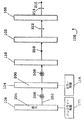
図2は、チューナブルミラー104が、陰200のないことで示される透過モードで動作するように切り替えられる透過モードでのLCD100の動作を示す。さらに、バックライト106は、発光の動作状態204に切り替えられる。図1の説明と同様に、液晶セル102は再び直線偏光された光の偏光面を90°回転させると仮定する。まず、非偏光光ベクトル206で示される不規則に偏光されたバックライト発光202は、チューナブルミラー104を主に透過する。ベクトル208で示される結果として得られる非偏光光は、第2の偏光子110を通過し、直線偏光される210。それから、その偏光は液晶セル102によって、第1の偏光子108の透過軸にほぼ平行な直線偏光212に回転される。最後に、光は、直線偏光214を有する第1の偏光子108から出射して、LCD出力216として現れる(液晶セル102がオフ状態のときには、液晶セル102から出射する光は、第1の偏光子108の透過軸と直交する偏光方向を有し、遮断される)。
チューナブルミラー
本発明の目的のために、チューナブルミラーは、制御可能な透過率と反射率を有する任意の素子として定義される。制御可能な透過率と反射率には、不連続な状態または連続した状態で切り替え可能な透過率・反射率が含まれる。電気光学素子は、電気信号によりその光学特性が変化する素子である。本発明は、部分透過型LCD用のチューナブルミラーとして振る舞う任意の電気光学素子または他の素子の使用を意図している。
【0026】
Tenchの特許(米国特許第5,923,456号)は、制御可能な反射モードと屈折モードを有する反転可能電気化学ミラー(REM)を開示している。REMは、極性が反転可能で電位が調整可能な電位源を適用することで制御できる。REMは、反射モードと透過モードとの切り替えに約1秒かかる。さらに、REMは、拡散反射率を生じるように艶消し表面を有することもある。REMは、光の吸収のため、達成可能な透過率が最大60%であり、そのため効率が限定される。
【0027】
さらに、チューナブルミラーは、そのうちの少なくとも1つが切り替え可能な光学的性質を有する電気光学素子である複数の光学要素を組み合わせて構築可能である。図3〜17は、本発明によるそのようなチューナブルミラーとそれらのミラーを内蔵するLCDの例を示す。
【0028】
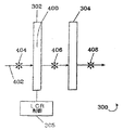
図3〜6は、第1のチューナブルミラーアセンブリ300と、チューナブルミラー300を内蔵するLCD500を示す。チューナブルミラー300は、4分の1波(λ/4)リターダ304を有する切り替え可能コレステリック液晶リフレクタ302と液晶リフレクタ302用の制御部305とを備える。液晶リフレクタ302は、反射状態と透過状態との間で動作を制御により切り替え可能であり、反射状態で特定の回転方向に円偏光された光を反射し、透過状態で光を透過する。そのようなコレステリック液晶素子は、Kent DisplaysとAdvanced Display Systems (ADS)から市販されている。コレステリック液晶リフレクタ302は、LCD全体と同一の寸法を有する単一アドレス指定画素を有するように専用に設計されることが好ましい。そのような液晶リフレクタは、反射状態では拡散反射性があり、したがって、光拡散素子を追加することなく拡散画像を生成する。電圧(約20〜80ボルト)がリフレクタ302に印加されると(つまり透過状態において)、リフレクタは偏光の変化なしに光が透過するホメオトロピック状態から変化する(D. K. Yang, J. L. West, L. C. Chien, J. W. DOANE,”Control of Reflectivity and Bistability in Displays using Cholesteric Liquid Crystals”, J. APPL. Phys. 76、1331 (1994)を参照)。
【0029】
λ/4リターダ304は、円偏光形態と直線偏光形態との間で光を変換するのに使用される要素である。このリフレクタは、水平または垂直に直線偏光光を、その方向に従って、右回転または左回転に円偏光された光に変換する。逆に、このリフレクタは、右回転または左回転に円偏光された光を直線偏光された光に変換し、不規則に偏光された光を実質的に透過する。そのようなλ/4リターダは、複屈折結晶または配向ポリマーフィルムにより実現することが可能で、Fuji Film、Nitto Denko、Meadowlark Opticsにより製造される(Polarization Manipulation with Retarders, Meadowlark Optics, Product Catalogue, 1999−2000を参照)。
【0030】
さらに、液晶リフレクタ302とλ/4リターダ304は、反射モードではリフレクタ302がリターダ304から受光した光を反射するように、互いに向きが設定されている。また、図3〜6では、液晶リフレクタ302とλ/4リターダ304が分離しているように図示されているが、LCDの構成部品として、これらの要素は通常1つに接合される。
【0031】
図3は、液晶リフレクタ302が反射状態になる反射モードでのチューナブルミラー300の動作を示している。この状態では、液晶リフレクタ302は、円反射ベクトル306で示された1つの特定の回転方向、たとえば、左回転ではなく、右回転に円偏光された光を反射することができる。
【0032】
まず、偏光光ベクトル312で示される直線偏光された光308(たとえば、水平方向)は、λ/4リターダ304によって、偏光光ベクトル314で示される右回転の円偏光に変換される。それから、光は液晶リフレクタ302により右回転円偏光316を維持したまま反射され、水平直線偏光318に戻すように変換するλ/4リターダ304を透過して戻される。
【0033】
図4は、液晶リフレクタ302が透過状態になる透過モードでのチューナブルミラー300の動作を示している。この状態では、反射ベクトルが存在しないこと400で示されるように、液晶リフレクタは光を透過する。非偏光光ベクトル404で示される不規則に偏光された光402は、ベクトル406と408で示される不規則な偏光を維持したまま、液晶リフレクタ302とλ/4リターダ304の両方を透過する。
【0034】
図5と6は、チューナブルミラー300を内蔵するLCD500の動作を示している。LCD500の要素は、実質的に前の図と同じであるが、チューナブルミラーとチューナブルミラー制御部が異なる。これらの要素は、チューナブルミラー300のλ/4リターダ304の前面に配置された液晶セル502、チューナブルミラー300の液晶リフレクタ302の背面に配置され、発光状態と非発光状態との間で切り替え可能なバックライト506、セル502の前面の第1の偏光子508、セル502とλ/4リターダ304との間の第2の偏光子510、およびバックライト506用の制御部520である。ここでも、図示のために、液晶セル502は、ノーマリホワイトモードで動作する90°TNセルで、直線偏光された光の偏光面を90°回転させるオン状態にあると仮定する。また、図示のために、第1の偏光子と第2の偏光子508と510は、それぞれ互いに直交する垂直方向と水平方向の偏光面を有する。
【0035】
図5は、円反射ベクトル306で示すように液晶リフレクタ302が反射状態にあり、バックライト506が非発光状態526にある反射モードで動作しているLCD500を示す。まず、非偏光光ベクトル530で示される不規則に偏光した周囲光526が、第1の偏光子508を通過して、偏光光ベクトル532で示されるように、通過時に直線偏光される。それから、光は液晶セル502を通過し、偏光光ベクトル534で示すように、通過時に第2の偏光子の透過軸にほぼ平行な偏光面を有するように回転され、直線偏光536を維持したまま第2の偏光子510を通過する。
【0036】
それから、光はλ/4リターダ304を通過し、通過時に右回転方向538に円偏光される。それから、円偏光した光538は、液晶リフレクタ302で反射され、一連の偏光540、542、544、546、548を有する逆の経路をたどり、LCD出力550として出射する(液晶セル502がオフ状態のときには、第1の偏光子508を通って入射する光は、セル502を通過し、通過時に第2の偏光子510の透過軸にほぼ直交する偏光面を有するように回転され、遮断される)。
【0037】
図6は、反射ベクトル400がないことで示されるように液晶リフレクタが透過状態にあり、バックライトが発光状態600のにある透過モードで動作しているLCD500を示す。まず、非偏光光ベクトル606で示された不規則に偏光されたバックライト602は、非偏光光ベクトル607と608を有しながら、液晶リフレクタ302とλ/4リフレクタ304を通過する。通過後の光は、第2の偏光子510を通過し、直線偏光される610。それから、その偏光は液晶セル502によって、第1の偏光子508の透過軸にほぼ平行な直線偏光612に回転される。最後に、光は、直線偏光614を有する第1の偏光子508を通過し、LCD出力616として出射する(液晶セル502がオフ状態のときには、セル502から出射する光は、第1の偏光子508の透過軸と直交する偏光方向を有し、遮断される)。
【0038】
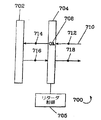
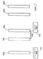
図7〜12は、第2のチューナブルミラーアセンブリ700と、チューナブルミラー700を内蔵するLCD900、1100、1200を示す。チューナブルミラー700は、反射偏光子702、ゼロ−半波(0−λ/2)チューナブル液晶リターダ704、および0−λ/2リターダ704用の制御部705を備える。反射偏光子702は、1方向(たとえば水平方向)に直線偏光された光を反射し、別の方向(たとえば垂直方向)に偏光された光を透過する。市販の反射偏光子(Merckと3Mから供給される)は、拡散反射性ではなく正反射性を有する。
【0039】
0−λ/2リターダ704は、0λとλ/2状態との間で動作を制御により切り替え可能で、λ/2状態では直線偏光された光の偏光面を90°回転させ、0λ状態では変化なしに光を透過させる(Meadowlark Opticsのカタログを参照)。そのようなリターダは、通常ネマチック型で、電圧(約10V)を印加することで20msの速度で0λ状態に切り替え可能で、アナログモードで動作する。
【0040】
さらに、図7〜12に示すように、反射偏光子702とリターダ704は、反射モードでは、反射偏光子702がリターダ704から受光した光を反射するように互いに向きが設定されている。また、図7〜12では、反射偏光子702とリターダ704が分離しているように図示されているが、LCDの構成部品として、これらの要素は通常1つに接合される。さらに、拡散反射が望ましいLCDでは、この種のチューナブルミラーに光拡散要素を追加することもできる。その場合、偏光を乱さないホログラフィックディフューザの使用が好ましい。
【0041】
図7は、0−λ/2リターダ704が0λ状態708である反射モードでのチューナブルミラー700の動作を示す。最も簡単な場合、偏光光ベクトル712で示される水平直線偏光710を有する光がリターダ704を透過し、反射偏光子702で反射され、リターダ704を通過して戻り、一連の偏光714、716、718を有する。入射する光が水平と垂直の両方の偏光成分を有することも可能である。その場合も、水平直線偏光を有する成分だけが反射されて戻る。
【0042】
図8は、リターダ704がλ/2状態800である透過モードでのチューナブルミラー700の動作を示す。まず、非偏光光ベクトル804で示される不規則に偏光された光802が反射偏光子702を透過し、透過時には、偏光光ベクトル806で示したように、垂直成分だけが透過する。その後、光はリターダを通過し、通過時には、偏光光ベクトル808で示したように、光の偏光が90度回転される。
【0043】
図9と図10は、チューナブルミラー700を内蔵するLCD900の動作を示している。LCD900の要素は、実質的に前の図と同じであるが、チューナブルミラーとチューナブルミラー制御部が異なる。これらの要素は、チューナブルミラー700の0−λ/2リターダ704の前面に配置された液晶セル902、チューナブルミラー700の反射偏光子702の後面に配置され、発光状態と非発光状態との間で動作を切り替え可能なバックライト906、セル902の前面の第1の偏光子908、セル902とリターダ704との間の第2の偏光子910、およびバックライト906用の制御部920である。ここでも、液晶セル902は、ノーマリホワイトモードで動作する90°TNセルで、直線偏光された光の偏光面を90°回転させるオン状態にあると仮定する。また、図示のために、第1の偏光子と第2の偏光子908と910は、それぞれ互いに直交する垂直方向と水平方向の偏光面を有する。
【0044】
図9は、リターダ704が0λ状態708で、バックライト906が非発光状態926の反射モードで動作しているLCD900を示している。まず、非偏光光ベクトル930で示される不規則に偏光した周囲光928が、第1の偏光子908を通過して、通過時に偏光光ベクトル932で示されるように、直線偏光される。それから、光は液晶セル902を通過し、偏光光ベクトル934で示されるように、通過時に第2の偏光子910の透過軸にほぼ平行な偏光面を有するように回転され、直線偏光936を維持したまま第2の偏光子910を通過する。それから、光は、直線偏光938を維持したまま0−λ/2リターダ704を透過し、反射偏光子702により反射して戻される。それから、光は、一連の偏光940、942、944、946、948を有する逆の経路をたどり、LCD出力950として出射する(液晶セル902がオフ状態のときには、第1の偏光子908を通って入射する光は、セル902を通過し、通過時に第2の偏光子910の透過軸にほぼ直交する偏光面を有するように回転され、遮断される)。
【0045】
図10は、0−λ/2リターダ704がλ/2状態800で、バックライト906が発光状態1000の透過モードで動作しているLCD900を示している。まず、非偏光光ベクトル1004で示される不規則に偏光されたバックライト発光1002が反射偏光子702を通って透過し、透過時に偏光光ベクトル1006で示されるように、垂直成分だけが透過する。その後、光はリターダ704を通過し、通過時に偏光光ベクトル1008で示されるように、偏光が90度回転される。それから、光は、直線偏光1010を維持しながら第2の偏光子910を通過する。それから、その偏光は液晶セル902によって、第1の偏光子908の透過軸に平行なほぼ直線の偏光1012に回転される。最後に、光は、直線偏光1014を有する第1の偏光子908を通過し、LCD出力1016として出射する(液晶セル902がオフ状態のときには、セル902から出射する光は、第1の偏光子908の透過軸と直交する偏光方向を有し、遮断される)。
【0046】
図11は、λ/4リターダ1102がバックライト906と反射偏光子702との間に設置されたLCD900と同様のLCD1100を示す。当該技術分野で知られているように、λ/4リターダ1102をバックライト906と反射偏光子702との間に配置すると、ディスプレイの輝度を改善することができる。これは、透過モードで反射偏光子702により透過されない水平に偏光された光がλ/4リターダ1102を通して反射して戻るためである。それから、光は、右回転方向に円偏光され、リターダを通して左回転の円偏光された光として反射して戻される。それから、光は、リターダ1102を通して垂直直線偏光されて出射し、反射偏光子702を通過する(Taberの米国特許第5,731,886号を参照)。
【0047】
第2の偏光子910なしにLCD900を組み立てることも可能である。これは、反射偏光子702が、液晶セルにより回転されない光を除去することで第2の偏光子910の機能を果たすためである。図12はこのLCDアセンブリ1200を示している。
【0048】
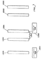
図13〜17は、第3のチューナブルミラーアセンブリ1300と、チューナブルミラー1300を内蔵するLCD1500と1700を示す。チューナブルミラー1300には、コレステリックリフレクタ1302と、負4分の1波−正4分の1波(+/−λ/4)液晶リターダ1304と+/−λ/4液晶リターダ用の制御部1306とが含まれる。
【0049】
コレステリックリフレクタ1302は、ある回転方向を有する円偏光された光を反射し、反対の回転方向に円偏光された光を透過する。コレステリックリフレクタ1302は、光を拡散する拡散反射コレステリック液晶ポリマーフィルムであってもよい。そのようなリフレクタは、Wacker−Chemie, R. Maurer, F. H. Kreuzer, J. Stohrer, ”Cholesteric Reflectors with a Color Pattern”, SID 94 Digest, p. 399 (1994)に記述された工程に従って作成することができる。
【0050】
+/−λ/4液晶リターダは、円偏光形態と直線偏光形態との間で光を変換するという点で、λ/4リターダと同様に機能する。しかし、+/−λ/4液晶リターダ1304は、2つの状態の間の光学位相遅れが半波長λ/2である−λ/4状態と+λ/4状態との間で動作を制御により切り替え可能である。+λ/4状態では、リターダ1304は、水平または垂直に直線偏光された光を右回転または左回転の円偏光された光にそれぞれ変換する。逆に、リターダ1304は、右回転または左回転の円偏光された光を水平または垂直に直線偏光された光にそれぞれ変換する。−λ/4状態では、リターダ1304は、水平または垂直に直線偏光された光を左回転または右回転に円偏光された光にそれぞれ変換し、逆に、右回転または左回転に円偏光された光を垂直または水平に直線偏光された光にそれぞれ変換する。そのようなリターダは、ネマチック型または強誘電型のいずれかである。ネマチック型は、λ/4リターダを0−λ/2波リターダと組み合わせることで作成することができる。適切なチューナブルリターダを構築する方法は他に存在する可能性もある。本発明は、2つの状態の間の光学位相遅れがλ/2だけ異なる2つの状態の間を制御により切り替え可能な任意の適切なリターダの使用を意図している。
【0051】
さらに、図13〜17に示すように、コレステリックリフレクタ1302とリターダ1304は、反射モードでは、コレステリックリフレクタ1302がリターダ1304から受光した光を反射するように互いに向きが設定されている。また、図13〜17では、コレステリックリフレクタ1302と+/−λ/4リターダリターダ1304が分離しているように図示されているが、LCDの構成部品として、これらの要素は通常1つに接合される。
【0052】
図13は、リターダ1304が+λ/4状態1308にあり、水平に直線偏光された光を右回転方向に円偏光された光に変換する反射モードでのチューナブルミラー1300の動作を示している。また、コレステリックリフレクタは、右回転に円偏光された光を反射して、左回転に円偏光された光を透過させる。最も簡単な場合では、偏光光ベクトル1314で示される水平直線偏光1312を有する光はリターダ1304を透過し、偏光ベクトル1316で示される右回転に円偏光された光に変換される。それから、光は、偏光1318を維持したままコレステリックリフレクタ1302により反射され、それからリターダ1304を通して直線偏光され元の水平偏光1302に戻される。入射する光が水平と垂直の両方の偏光を有することも可能である。その場合も、水平直線偏光を有する成分だけが右回転の円偏光に変換され、反射して戻される。
【0053】
図14は、+/−λ/4リターダ1304が−λ/4状態1400にある透過モードでのチューナブルミラー1300の動作を示す。まず、非偏光光ベクトル1404で示される不規則に偏光された光1402がコレステリックリフレクタ1302を透過し、透過時には、偏光光ベクトル1406で示されるように、左回転円偏光成分だけが透過する。その後、光はリターダ1304を通過し、通過時に水平直線偏光1408に直線偏光される。
【0054】
図15と16は、チューナブルミラー1300を内蔵するLCD1500の動作を示している。LCD1500の要素は、実質的に前の図と同じであるが、チューナブルミラーとチューナブルミラー制御部が異なる。これらの要素は、チューナブルミラー1300の+/−λ/4リターダ1504の前面に配置された液晶セル1502、チューナブルミラー1300のコレステリックリフレクタ1302の背面に配置され、発光状態と非発光状態との間で切り替え可能なバックライト1506、セル1502の前面の第1の偏光子1508、セル1502と+/−λ/4リターダ1304との間の第2の偏光子1510、およびバックライト1506用の制御部1520である。ここでも、液晶セル1502は、ノーマリホワイトモードで動作する90°TNセルで、直線偏光された光の偏光面を90°回転させるオン状態にあると仮定する。また、図示のために、第1の偏光子と第2の偏光子1508と1510は、それぞれ垂直の方向と水平の方向の互いに直交する偏光面1522と1524を有する。
【0055】
図15は、+/−λ/4リターダ1304が+λ/4状態1308で、バックライト1506が非発光状態1526の反射モードで動作しているLCD1500を示している。まず、非偏光光ベクトル1530で示される不規則に偏光した周囲光1528が、第1の偏光子1508を通過して、偏光光ベクトル1532で示されるように直線偏光される。それから、光は液晶セル1502を通過し、偏光光ベクトル1534で示されるように、通過時に第2の偏光子の透過軸にほぼ平行な偏光面を有するように回転され(約90°)、それから、直線偏光1536を維持したまま第2の偏光子1510を通過する。それから、光はリターダ1304を透過し、偏光ベクトル1538で示されるように右回転方向に円偏光される。それから、光は、コレステリックリフレクタ1302によって反射されて戻る。それから、光は、一連の偏光1540、1542、1544、1546、1548を有する逆の経路をたどり、LCD出力1550として出射する(液晶セルがオフ状態のときには、第1の偏光子1508を通って入射する光は、セル1502を通過し、通過時に第2の偏光子1510の透過軸にほぼ直交する偏光面を有するように回転され、遮断される)。
【0056】
図16は、リターダ1304が−λ/4状態1400で、バックライト1506が発光状態1600の反射モードで動作しているLCD1500を示している。まず、非偏光光ベクトル1604で示される不規則に偏光されたバックライト発光1602が反射偏光子1302を透過し、透過時には、偏光光ベクトル1606で示されるように、左回転の円偏光成分だけが透過する。その後、光はリターダ1304を通過し、通過時に水平直線偏光1608に直線偏光される。それから、光は、直線偏光1610を維持しながら第2の偏光子1510を通過する。それから、その偏光は液晶セル1502によって、第1の偏光子1508の透過軸にほぼ平行な直線偏光1612に回転される。最後に、光は、直線偏光1614を有する第1の偏光子1508を通過し、LCD出力1616として出射する(セルがオフ状態のときには、液晶セル1502から出射する光は、第1の偏光子1508の透過軸と直交する偏光方向を有し、遮断される)。
【0057】
当該技術分野で知られているように(Taberの米国特許第5,731,886号を参照)、コレステリックリフレクタ1302から反射される右回転の光は、バックライト表面からの反射時に180°の位相変化をし、右回転円偏光が左回転円偏光に変化し、ディスプレイの輝度を改善する。
【0058】
第2の偏光子1510なしにLCD1500を組み立てることも可能である。これは、コレステリックリフレクタ1302が、液晶セルにより回転されない光を除去することで第2の偏光子1510の役割を果たすためである。図17はこのLCDアセンブリ1700を示している。
【0059】
前述の反射モードと透過モードに加え、LCDとチューナブルミラーは、チューナブルミラーとバックライトが中間状態で動作する中間動作モードを任意選択で含んでもよい。
【0060】
前述の任意の実施形態によるチューナブルミラーを備えたLCDは、多種の動作システムに組み込み可能であり、動作システムには、全地球測位衛星(GPS)受信ユニット、ラップトップユニットやノートパッドユニットを含むコンピュータ、PDA、電卓、個人用カレンダ、携帯電話、腕時計および置き時計、自動車用のディスプレイ、飛行機用のディスプレイ、船舶用のディスプレイが含まれるが、これらには限定されない。
【0061】
本発明を実施する動作システムの3つの例を図18a〜18cに示す。図18aは、本発明のLCD1802を備えた携帯電話1800である。図18bは、本発明のLCD1806を備えた腕時計1804、図18cは、キーパッド部分1812に取り付けられた本発明のLCD画面1810を備えたラップトップ1808である。携帯電話、腕時計、ラップトップコンピュータは、電池で動作可能なため、本発明のLCDを使用すると、電池寿命が節約され、さらにディスプレイのコントラストと輝度が増加するので望ましい。
【図面の簡単な説明】
【図1】
反射モードで動作している本発明に従ったLCDの概略図である。
【図2】
透過モードで動作している図1のLCDの概略図である。
【図3】
反射モードで動作している液晶リフレクタと4分の1波リターダを含むチューナブルミラーの概略図である。
【図4】
透過モードで動作している図3のチューナブルミラーの概略図である。
【図5】
反射モードで動作している図3のチューナブルミラーを有するLCDの概略図である。
【図6】
透過モードで動作している図5のLCDの概略図である。
【図7】
反射モードで動作している0−半波(0−λ/2)チューナブル液晶リターダを有する反射偏光子を含むチューナブルミラーの概略図である。
【図8】
透過モードで動作している図7のチューナブルミラーの概略図である。
【図9】
反射モードで動作している図7のチューナブルミラーを有するLCDの概略図である。
【図10】
透過モードで動作している図9のLCDの概略図である。
【図11】
λ/4リターダを備える図7のチューナブルミラーを有するLCDの代替の構造の概略図である。
【図12】
図8のチューナブルミラーを有するLCDの代替の構造の概略図である。
【図13】
反射モードで動作している負4分の1波−正4分の1波(+/−λ/4)チューナブル液晶リターダを有するコレステリックリフレクタを含むチューナブルミラーの概略図である。
【図14】
透過モードで動作している図13のチューナブルミラーの概略図である。
【図15】
反射モードで動作している図13のチューナブルミラーを有するLCDの概略図である。
【図16】
透過モードで動作している図15のLCDの概略図である。
【図17】
図13のチューナブルミラーを有するLCDの代替の構造の概略図である。
【図18】
図18a〜図18cは、本発明の電子装置の外観を示す斜視図で、図18aは携帯電話、図18bは腕時計、zy18cはラップトップコンピュータである。[0001]
TECHNICAL FIELD OF THE INVENTION
The present invention relates to a liquid crystal display (LCD), and more particularly to a transflective LCD with low battery consumption and high contrast.
[0002]
[Prior art]
Conventional transflective LCDs reflect ambient light received from a screen through the LCD and return the transflective mirror elements (also known as transflectors) that transmit backlight emitted when the ambient illumination is weak. Has been).
[0003]
In a conventional transflective LCD, light is reflected and transmitted at the same time by a partially reflecting / partially transmitting mirror, so that the use of light is inefficient. Further, the transmittance and the reflectance are fixed values. At any given time, the sum of the transmittance and the reflectance of the mirror cannot exceed 100%, so the partial reflection / partial transmission mirror operates at the same time as a reflector and a transmission plate, at the expense of efficiency. I have. Usually such mirrors have a reflectivity of 70-90% and a transmittance of 10-30%.
[0004]
To compensate for such inefficiencies, more battery power must be used to increase backlight emission when operating in transmission mode with low ambient light. Similarly, contrast is lost when operating in a reflective mode where the ambient light is strong.
[0005]
Summary of the Invention
The present invention provides a system and method for improving the efficiency of a conventional partially transmissive LCD by replacing a partially reflective and partially transmissive mirror with a tunable mirror. A tunable mirror is any element whose degree of transmittance and reflectance can be controlled.
[0006]
The advantage of using a tunable mirror is that it can switch between reflective mode and transmissive mode, reflecting mainly light when the ambient lighting is strong, and mainly transmitting light when the ambient lighting is weak and need back lighting That is. This saves battery life by reducing the amount of backlight required when operating the LCD in transmissive mode, and increases contrast and brightness when operating in reflective mode.
[0007]
Reversible electrochemical mirrors (REMs) are a type of tunable mirror suitable for use in the present invention. Furthermore, a tunable mirror can be constructed from a plurality of optical elements, at least one of which has an electrically switchable optical property.
[0008]
One suitable structure for a tunable mirror comprises a cholesteric liquid crystal reflector having a quarter wave (λ / 4) retarder. In this combination, the liquid crystal reflector can switch operation between a reflective state and a transmissive state, giving the mirror an adjustable property.
[0009]
Another suitable structure for a tunable mirror comprises a reflective polarizer with a zero-half wave (0-λ / 2) tunable liquid crystal retarder. Such a retarder can switch operation between the λ / 2 and 0λ states, giving the mirror an adjustable nature.
[0010]
A third suitable configuration for a tunable mirror comprises a cholesteric reflector having a negative quarter wave to a positive quarter wave (+/- λ / 4) tunable retarder. Such a retarder can switch operation between + λ / 4 and −λ / 4 states, giving the mirror an adjustable property.
[0011]
Various controls are possible for the mirror and the backlight. For example, a mirror control system and a backlight control system that operate the mirror and the backlight in series so that the mirror is set to the transmission state when the backlight is turned on can be adopted. It is also possible to set the control of the mirror and the backlight to automatically correspond to the level of the ambient light.
[0012]
DESCRIPTION OF THE PREFERRED EMBODIMENTS
The present invention replaces the partially reflecting and partially transmitting mirrors used in prior art partially transmitting LCDs with tunable mirrors. There are many ways to create a partially transmissive LCD. Although a particular type of LCD is shown in the figures, the invention is generally applicable to any partially transmissive LCD where the partially reflective and partially transmissive mirror can be replaced by a tunable mirror.
[0013]
FIGS. 1 and 2 show the
The
[0014]
The
[0015]
In a normally white mode of operation, the
[0016]
In an STN cell, the planes of polarization may not be orthogonal. A normally black mode can also be used, in which case a voltage is applied in the on state and no voltage is applied in the off state. In the example of a 90 ° TN cell operating in a normally black mode, the polarizers are parallel (for reference information about TN cells, see TJ Scheffer, J. Nehring, “Supertwisted Nematic LCDS”, Society for Information). Display Seminar Lecture Notes, Vol. 1, M-12, May 15, 2000 and references therein).
[0017]
The
[0018]
The
[0019]
Although the
[0020]
Other optional components, other than the components shown, are not shown, as they are not required for the description of the present invention. These elements include compensating (retardation) films that can be placed on either side of the
[0021]
Furthermore, a light diffusion element can be added to generate a diffuse image. Such light diffusing elements can be made from embossed plastic plates or plastic plates with dispersed beads. In addition, the beads to be dispersed can be mixed into one of the adhesive layers adjacent to any of the above elements (see Okumura patent). In addition, as described in more detail in the description of the tunable mirror, it is possible to create a tunable mirror with a matte surface to obtain a diffusing surface, and some mirrors originally have a property of diffusing light. In that case, no additional light diffusing element is needed for diffusion.
[0022]
Further, in a conventional partially transmissive LCD, the backlight is switched to a light emitting state when operating in the transmissive mode. In the present invention, both the backlight and the tunable mirror need to be controlled. There are several control methods that can be selected. The mirror controls and backlight controls 118 and 120 can either be set manually by the user or automatically respond to ambient light levels. The user can also select whether to set the control unit in a manual mode or an automatic ambient light mode. Systems that automatically respond to ambient light use an ambient light sensor, for example, to switch the backlight to the illuminated state when ambient light is weak, set the mirror to transmissive mode, and The backlight can be switched to a non-light emitting state and the mirror can be set to the reflection mode. Further, the two
[0023]
FIG. 1 illustrates the operation of
[0024]
First, the irregularly polarized
[0025]
FIG. 2 illustrates operation of
Tunable mirror
For the purposes of the present invention, a tunable mirror is defined as any element having a controllable transmission and reflectance. The controllable transmittance and reflectance include transmittance and reflectance that can be switched in a discontinuous state or a continuous state. An electro-optical element is an element whose optical characteristics change according to an electric signal. The present invention contemplates the use of any electro-optic or other element that acts as a tunable mirror for a partially transmissive LCD.
[0026]
The Tench patent (US Pat. No. 5,923,456) discloses a reversible electrochemical mirror (REM) having controllable reflective and refractive modes. REM can be controlled by applying a potential source whose polarity can be inverted and whose potential can be adjusted. REM takes about 1 second to switch between the reflection mode and the transmission mode. In addition, REMs may have a matte surface to create diffuse reflectance. REM has a maximum achievable transmission of up to 60% due to light absorption, which limits its efficiency.
[0027]
Further, a tunable mirror can be constructed by combining a plurality of optical elements, each of which is an electro-optical element having at least one switchable optical property. 3 to 17 show examples of such tunable mirrors according to the invention and LCDs incorporating them.
[0028]
3 to 6 show a first
[0029]
The λ / 4
[0030]
Further, the orientations of the
[0031]
FIG. 3 shows an operation of the
[0032]
First, the linearly polarized light 308 (for example, in the horizontal direction) indicated by the polarized
[0033]
FIG. 4 shows an operation of the
[0034]
5 and 6 show the operation of the
[0035]
FIG. 5 shows the
[0036]
The light then passes through the λ / 4
[0037]
FIG. 6 shows an
[0038]
7 to 12 show a second
[0039]
The 0-λ / 2
[0040]
Further, as shown in FIGS. 7 to 12, the
[0041]
FIG. 7 shows the operation of the
[0042]
FIG. 8 shows the operation of the
[0043]
9 and 10 show the operation of the
[0044]
FIG. 9 shows the
[0045]
FIG. 10 shows
[0046]
FIG. 11 shows an
[0047]
It is also possible to assemble the
[0048]
13 to 17 show a third
[0049]
[0050]
The +/- λ / 4 liquid crystal retarder functions similarly to a λ / 4 retarder in that it converts light between a circularly polarized form and a linearly polarized form. However, the +/- λ / 4
[0051]
Further, as shown in FIGS. 13 to 17, the
[0052]
FIG. 13 shows the operation of the
[0053]
FIG. 14 shows the operation of the
[0054]
15 and 16 show the operation of the
[0055]
FIG. 15 shows an
[0056]
FIG. 16 shows the
[0057]
As is known in the art (see Taber, US Pat. No. 5,731,886), clockwise rotating light reflected from the
[0058]
It is also possible to assemble the
[0059]
In addition to the above-mentioned reflection mode and transmission mode, the LCD and the tunable mirror may optionally include an intermediate operation mode in which the tunable mirror and the backlight operate in an intermediate state.
[0060]
An LCD with a tunable mirror according to any of the embodiments described above can be incorporated into a variety of operating systems, including a global positioning satellite (GPS) receiving unit, a laptop unit and a notepad unit. Includes, but is not limited to, computers, PDAs, calculators, personal calendars, mobile phones, watches and clocks, displays for automobiles, displays for airplanes, displays for ships.
[0061]
18a-18c show three examples of operating systems embodying the present invention. FIG. 18a shows a mobile phone 1800 provided with the LCD 1802 of the present invention. FIG. 18b is a wristwatch 1804 with an LCD 1806 of the present invention, and FIG. 18c is a laptop 1808 with an LCD screen 1810 of the present invention mounted on a keypad portion 1812. Cell phones, watches, and laptop computers can be battery operated, so using the LCD of the present invention is desirable because it saves battery life and also increases the contrast and brightness of the display.
[Brief description of the drawings]
FIG.
1 is a schematic diagram of an LCD according to the present invention operating in a reflection mode.
FIG. 2
FIG. 2 is a schematic diagram of the LCD of FIG. 1 operating in a transmission mode.
FIG. 3
FIG. 2 is a schematic diagram of a tunable mirror including a liquid crystal reflector operating in a reflection mode and a quarter wave retarder.
FIG. 4
FIG. 4 is a schematic diagram of the tunable mirror of FIG. 3 operating in a transmission mode.
FIG. 5
FIG. 4 is a schematic diagram of an LCD having the tunable mirror of FIG. 3 operating in a reflection mode.
FIG. 6
FIG. 6 is a schematic diagram of the LCD of FIG. 5 operating in a transmission mode.
FIG. 7
FIG. 2 is a schematic diagram of a tunable mirror including a reflective polarizer with a 0-half-wave (0-λ / 2) tunable liquid crystal retarder operating in a reflective mode.
FIG. 8
FIG. 8 is a schematic diagram of the tunable mirror of FIG. 7 operating in a transmission mode.
FIG. 9
FIG. 8 is a schematic diagram of an LCD having the tunable mirror of FIG. 7 operating in a reflection mode.
FIG. 10
FIG. 10 is a schematic diagram of the LCD of FIG. 9 operating in a transmission mode.
FIG. 11
8 is a schematic diagram of an alternative structure of an LCD having the tunable mirror of FIG. 7 with a λ / 4 retarder.
FIG.
FIG. 9 is a schematic diagram of an alternative structure of the LCD having the tunable mirror of FIG.
FIG. 13
FIG. 3 is a schematic diagram of a tunable mirror including a cholesteric reflector having a negative quarter-positive quarter-wave (+/− λ / 4) tunable liquid crystal retarder operating in a reflective mode.
FIG. 14
FIG. 14 is a schematic diagram of the tunable mirror of FIG. 13 operating in a transmission mode.
FIG.
FIG. 14 is a schematic diagram of an LCD having the tunable mirror of FIG. 13 operating in a reflection mode.
FIG.
FIG. 16 is a schematic diagram of the LCD of FIG. 15 operating in a transmission mode.
FIG.
FIG. 14 is a schematic diagram of an alternative structure of the LCD having the tunable mirror of FIG.
FIG.
18A to 18C are perspective views showing the appearance of the electronic device of the present invention. FIG. 18A shows a mobile phone, FIG. 18B shows a wristwatch, and zy18c shows a laptop computer.
Claims (68)
前記液晶セルに光学的に揃えられ、制御可能な反射モードと透過モードを有し、該反射モードでは主に前記液晶セルから受光した光を反射して戻して該セルを通過させ、該透過モードでは主に前記液晶セルに向けて光を透過するチューナブルミラーと
を備えた液晶(LCD)。A liquid crystal cell,
The liquid crystal cell is optically aligned and has a controllable reflection mode and a transmission mode. In the reflection mode, light mainly received from the liquid crystal cell is reflected and returned to pass through the cell, A liquid crystal (LCD) mainly comprising a tunable mirror that transmits light toward the liquid crystal cell.
前記第2の偏光要素と前記液晶セルとの間の第2のA板と
をさらに備えた請求項6に記載のLCD。A first A plate between the first polarizing element and the liquid crystal cell;
7. The LCD according to claim 6, further comprising a second A plate between the second polarizing element and the liquid crystal cell.
前記バックライトを発光状態と非発光状態との間で動作を切り替える第2の制御システムと
をさらに備えた請求項4に記載のLCD。A first control system for switching the tunable mirror between a reflection mode and a transmission mode;
The LCD according to claim 4, further comprising: a second control system that switches an operation of the backlight between a light emitting state and a non-light emitting state.
前記バックライトは、さらに、部分的に前記LCDを照明する少なくとも1つの中間動作状態で動作可能である請求項4に記載のLCD。The tunable mirror further partially reflects the light received from the liquid crystal cell and returns the light through the cell, and at least partially transmits the light received from the backlight toward the liquid crystal cell. Can operate in one intermediate mode,
The LCD of claim 4, wherein the backlight is further operable in at least one intermediate operating state that partially illuminates the LCD.
前記第2の直線方向に直線偏光された光を第2の回転方向に円偏光された光に円偏光し、前記第2の回転方向に円偏光された光を前記第2の直線方向に直線偏光した光に直線偏光するための4分の1波(λ/4)リターダであって、不規則に偏光された光に対しては実質的に透過的なλ/4リターダと、
前記λ/4リターダに光学的に揃えられた前記液晶セルと反対側の液晶リフレクタであって、透過状態と反射状態との間で動作を制御により切り替え可能で、該反射状態で前記第2の回転方向に円偏光された光を反射し、該透過状態で光を透過するための液晶リフレクタとを備え、
前記チューナブルミラーは、前記液晶リフレクタが前記反射状態のときには前記反射モードで動作し、前記液晶リフレクタが前記透過状態のときには前記透過モードで動作する請求項4に記載のLCD。The tunable mirror is
The light linearly polarized in the second linear direction is circularly polarized into light circularly polarized in a second rotational direction, and the light circularly polarized in the second rotational direction is linearly polarized in the second linear direction. A quarter wave (λ / 4) retarder for linearly polarizing the polarized light, wherein the λ / 4 retarder is substantially transparent to randomly polarized light;
A liquid crystal reflector optically aligned with the λ / 4 retarder on the opposite side of the liquid crystal cell, the operation of which can be switched between a transmission state and a reflection state by control, and the second state in the reflection state; A liquid crystal reflector for reflecting light circularly polarized in the rotation direction and transmitting light in the transmission state,
The LCD according to claim 4, wherein the tunable mirror operates in the reflection mode when the liquid crystal reflector is in the reflection state, and operates in the transmission mode when the liquid crystal reflector is in the transmission state.
2つの状態の光学位相遅れがλ/2である第1の状態と第2の状態との間で動作を制御により切り替え可能なチューナブルリターダと、
前記液晶セルの反対側で前記リターダに光学的に揃えられ、前記リターダが前記第1の状態では該リターダから受光した光を反射し、該リターダが前記第2の状態では光を該リターダを通して透過させる反射偏光子とを備え、
前記チューナブルミラーは、前記リターダが前記第1の状態のときには前記反射モードで動作し、該リターダが前記第2の状態のときには前記透過モードで動作する請求項4に記載のLCD。The tunable mirror element is
A tunable retarder capable of controlling the operation to switch between a first state and a second state in which the optical phase delay of the two states is λ / 2;
Optically aligned with the retarder opposite the liquid crystal cell, the retarder reflects light received from the retarder in the first state, and transmits light through the retarder in the second state. And a reflective polarizer that causes
The LCD according to claim 4, wherein the tunable mirror operates in the reflection mode when the retarder is in the first state, and operates in the transmission mode when the retarder is in the second state.
0λ状態とλ/2状態との間で動作を制御により切り替え可能で、該λ/2状態では前記第1の方向に直線偏光された光の偏光面を前記第2の方向に直線偏光された光に回転し、該0λ状態では光を透過するゼロ−半波(0−λ/2)リターダと、
前記液晶セルの反対側で前記0−λ/2リターダに光学的に揃えられ、前記第2の方向に直線偏光された光を反射し、前記第1の方向の直線偏光を有する光を透過する反射偏光子とを備え、
前記チューナブルミラーは、前記0−λ/2リターダが前記0λ状態のときには前記反射モードで動作し、前記0−λ/2リターダが前記λ/2状態のときには前記透過モードで動作する請求項4に記載のLCD。The tunable mirror element is
The operation can be switched between the 0λ state and the λ / 2 state by control. In the λ / 2 state, the plane of polarization of light linearly polarized in the first direction is linearly polarized in the second direction. A zero-half-wave (0-λ / 2) retarder that rotates into light and transmits light in the 0λ state;
Opposite to the liquid crystal cell, it is optically aligned with the 0-λ / 2 retarder, reflects light linearly polarized in the second direction, and transmits light having linear polarization in the first direction. With a reflective polarizer,
5. The tunable mirror operates in the reflection mode when the 0-λ / 2 retarder is in the 0λ state, and operates in the transmission mode when the 0-λ / 2 retarder is in the λ / 2 state. LCD described in 1.
2つの状態の光学位相遅れがλ/2である動作の第1の状態と第2の状態との間で動作を制御により切り替え可能なチューナブルリターダと、
前記液晶セルの反対側で前記リターダに光学的に揃えられ、前記第1の状態の該リターダから受光した光を反射し、前記第2の状態の該リターダを通して光を透過するコレステリックリフレクタとを備え、
前記チューナブルミラーは、前記リターダが前記第1の状態のときには前記反射モードで動作し、該リターダが前記第2の状態のときには前記透過モードで動作する請求項4に記載のLCD。The tunable mirror is
A tunable retarder capable of controlling the operation to switch between a first state and a second state of operation in which the optical phase delay of the two states is λ / 2;
A cholesteric reflector that is optically aligned with the retarder on the opposite side of the liquid crystal cell, reflects light received from the retarder in the first state, and transmits light through the retarder in the second state. ,
The LCD according to claim 4, wherein the tunable mirror operates in the reflection mode when the retarder is in the first state, and operates in the transmission mode when the retarder is in the second state.
それにより、前記リターダは、前記+λ/4状態では第2の直線方向に直線偏光された光を第2の回転方向に円偏光された光に変換し、前記第2の回転方向に円偏光された光を前記第2の直線方向に直線偏光された光に変換し、前記リターダは、前記+λ/4状態では第1の回転方向に円偏光された光を前記第2の直線方向に直線偏光された光に変換し、
それにより、前記コレステリックリフレクタは前記第2の回転方向に円偏光された光を反射し、不規則に偏光された光の前記第1の回転方向の円偏光を有する成分を透過し、
前記チューナブルミラーは、前記+/−λ/4リターダが前記+λ/4状態のときには前記反射モードで動作し、前記+/−λ/4リターダが前記−λ/4状態のときには前記透過モードで動作する請求項22に記載のLCD。The tunable retarder is a negative quarter wave-positive quarter wave (+/- λ / 4) retarder whose operation can be switched between a -λ / 4 state and a + λ / 4 state by control. Yes,
Thereby, in the + λ / 4 state, the retarder converts light linearly polarized in the second linear direction into light circularly polarized in the second rotational direction, and is circularly polarized in the second rotational direction. The retarder converts the light circularly polarized in the first rotation direction in the + λ / 4 state into linearly polarized light in the second linear direction. Is converted into light
Thereby, the cholesteric reflector reflects circularly polarized light in the second rotational direction, and transmits a component of the irregularly polarized light having circularly polarized light in the first rotational direction,
The tunable mirror operates in the reflection mode when the +/− λ / 4 retarder is in the + λ / 4 state, and operates in the transmission mode when the +/− λ / 4 retarder is in the −λ / 4 state. 23. The LCD of claim 22, which operates.
前記λ/4リターダに光学的に揃えられた液晶リフレクタであって、反射状態と透過状態との間で動作を制御により切り替え可能で、前記反射状態で前記第1の回転方向に円偏光された光を反射し、前記透過状態で光を透過する、液晶リフレクタとを備え、
前記液晶リフレクタが前記反射状態にあるときには該液晶リフレクタとは反対側から前記λ/4リターダに入射する前記第1の直線方向に直線偏光された光を反射し、前記液晶リフレクタが前記透過状態にあるときには前記円偏光要素とは反対側から該液晶リフレクタに入射する光を透過するチューナブルミラー。The light linearly polarized in the first linear direction is circularly polarized into light circularly polarized in the first rotational direction, and the light circularly polarized in the first rotational direction is linearly polarized in the first linear direction. A quarter wave (λ / 4) retarder that linearly polarizes the polarized light, the λ / 4 retarder being substantially transparent to irregularly polarized light;
A liquid crystal reflector optically aligned with the λ / 4 retarder, the operation being switchable between a reflective state and a transmissive state by control, and circularly polarized in the first rotational direction in the reflective state. A liquid crystal reflector that reflects light and transmits light in the transmission state,
When the liquid crystal reflector is in the reflection state, it reflects light linearly polarized in the first linear direction incident on the λ / 4 retarder from a side opposite to the liquid crystal reflector, and the liquid crystal reflector is in the transmission state. In some cases, a tunable mirror that transmits light incident on the liquid crystal reflector from the side opposite to the circularly polarizing element.
前記0−λ/2リターダに光学的に揃えられ、該リターダから受光した前記第2の方向に直線偏光された光を反射して戻して前記リターダを通過させ、前記第1の方向の直線偏光を有する光を該リターダに向けて透過する反射偏光子とを備え、
前記0−λ/2リターダが前記0λ状態にあるときには前記反射偏光子とは反対側から該0−λ/2リターダを通して受光した前記第2の方向に直線偏光された光を反射し、前記0−λ/2リターダが前記λ/2状態にあるときには該0−λ/2リターダとは反対側から前記反射偏光子を通して受光した前記第1の方向の直線偏光を有する光を透過するチューナブルミラー。The operation can be switched between the 0λ state and the λ / 2 state by control, and in the λ / 2 state, the polarization plane of the light linearly polarized in the first direction is changed to light linearly polarized in the second direction. A zero-half-wave (0-λ / 2) retarder that rotates and transmits light in the 0λ state;
The linearly polarized light in the first direction is reflected optically aligned with the 0-λ / 2 retarder, reflected back from the retarder and linearly polarized in the second direction and passed through the retarder. A reflective polarizer that transmits light having the same toward the retarder,
When the 0-λ / 2 retarder is in the 0λ state, it reflects light linearly polarized in the second direction received through the 0-λ / 2 retarder from the side opposite to the reflective polarizer, and A tunable mirror that transmits light having linearly polarized light in the first direction received through the reflective polarizer from the side opposite to the 0-λ / 2 retarder when the λ / 2 retarder is in the λ / 2 state; .
それにより、前記+λ/4状態では、前記リターダは第1の直線方向に直線偏光された光を第1の回転方向に円偏光された光に円偏光し、前記第1の回転方向に円偏光された光を前記第1の直線方向に直線偏光された光に直線偏光し、前記−λ/4状態では、前記リターダは第2の回転方向に円偏光された光を第1の直線方向に直線偏光された光に直線偏光し、
前記+/−λ/4リターダに光学的に揃えられ、該+/−λ/4リターダから受光した前記第1の回転方向の偏光を有する円偏光された光を反射して戻して該+/−λ/4リターダを通過させ、前記第2の回転方向に円偏光された光を該+/−λ/4リターダに向けて透過させるコレステリックリフレクタを備え、
前記チューナブルミラーは、前記+/−λ/4リターダが前記+λ/4状態にあるときには前記コレステリックリフレクタとは反対側から前記+/−λ/4リターダを通して受光した前記第1の直線方向の直線偏光された光を反射し、前記+/−λ/4リターダが前記−λ/4状態にあるときには該+/−λ/4リターダとは反対側の前記コレステリックリフレクタを通して受光した前記第2の回転方向に円偏光された光を透過させるチューナブルミラー。A negative quarter wave-positive quarter wave (+/-. Lambda./4) retarder capable of controlling the operation between a -.lamda./4 state and a + .lamda. / 4 state by control;
Thereby, in the + λ / 4 state, the retarder circularly polarizes the light linearly polarized in the first linear direction into light circularly polarized in the first rotational direction, and circularly polarizes the light in the first rotational direction. Linearly polarized light into linearly polarized light in the first linear direction, and in the −λ / 4 state, the retarder converts circularly polarized light in the second rotational direction into the first linear direction. Linearly polarized light into linearly polarized light,
The circularly polarized light having the polarization in the first rotation direction, which is optically aligned with the +/- λ / 4 retarder and received from the +/- λ / 4 retarder, is reflected back to the +/- λ / 4 retarder. A cholesteric reflector that passes through a −λ / 4 retarder and transmits the circularly polarized light in the second rotational direction toward the +/− λ / 4 retarder;
When the +/- λ / 4 retarder is in the + λ / 4 state, the tunable mirror receives a straight line in the first linear direction received from the opposite side of the cholesteric reflector through the +/- λ / 4 retarder. The second rotation reflecting polarized light and receiving through the cholesteric reflector opposite the +/- λ / 4 retarder when the +/- λ / 4 retarder is in the -λ / 4 state; Tunable mirror that transmits circularly polarized light in the direction.
前記液晶セルの前記第1の側から入射する光の量が前記目視可能しきい値よりも低いときには、バックライト発光を生成し、前記液晶セルの前記第2の側から該液晶セルを通して該バックライト発光を主に透過することと
を含む液晶(LCD)を動作させる方法。When the amount of light incident from the first side of the liquid crystal cell exceeds the visible threshold, light incident from the first side of the liquid crystal cell and exiting from the second side of the liquid crystal cell, Mainly reflecting back and passing through the liquid crystal cell;
When the amount of light incident from the first side of the liquid crystal cell is lower than the visible threshold, a backlight emission is generated and the backlight is passed through the liquid crystal cell from the second side of the liquid crystal cell. A method of operating a liquid crystal (LCD), comprising: transmitting mainly light emission.
前記液晶セルの前記第1の側から入射する不規則に偏光された光を第1の偏光方向に直線偏光することと、
前記直接偏光された光を選択的に第2の偏光方向に回転させることであって、それにより前記第1と第2の偏光方向は相互に直交する、回転させることと、
前記第2の偏光方向を有する前記光を選択的に反射して戻し前記液晶セルを通過させるが、第1の偏光方向を有する光は反射しないこととを備えたこととを含む請求項33に記載の方法。The main reflection procedure is as follows:
Linearly polarizing irregularly polarized light incident from the first side of the liquid crystal cell in a first polarization direction;
Selectively rotating the directly polarized light in a second polarization direction, whereby the first and second polarization directions are orthogonal to each other, rotating;
Selectively reflecting and returning the light having the second polarization direction through the liquid crystal cell but not reflecting the light having the first polarization direction. The described method.
前記第2の偏光方向を有する前記光を透過するが、前記第1の偏光方向を有する光は透過しないことと、
前記第2の偏光方向を有する前記光を反射して戻し前記液晶セルを通過させることとを含む請求項34に記載の方法。The step of selectively reflecting includes:
Transmitting the light having the second polarization direction, but not transmitting the light having the first polarization direction;
35. The method of claim 34, comprising reflecting the light having the second polarization direction back through the liquid crystal cell.
前記生成されたバックライト発光を前記第2の直線偏光方向に偏光することと、
前記第2の直線偏光方向を有する前記光を前記第1の直線偏光方向に選択的に回転させることとを含む請求項34に記載の方法。The procedure mainly for transmission is as follows:
Polarizing the generated backlight emission in the second linear polarization direction;
35. The method of claim 34, comprising selectively rotating the light having the second linear polarization direction to the first linear polarization direction.
前記液晶セルの前記第1の側から入射する光がほとんどないときには、バックライト発光を生成し、前記液晶セルの前記第2の側から該液晶セルを通して該バックライト発光を主に透過させることと、
前記液晶セルの前記第1の側から入射する光が前記目視可能しきい値よりも低いときには、前記液晶セルの前記第1の側から入射し、前記液晶セルの前記第2の側から出射する光を反射して戻して該液晶セルを通過させ、バックライト発光を生成し、該バックライト発光を前記液晶セルの前記第2の側から該液晶セルを通して部分的に透過し、前記光が前記目視可能しきい値に達するように、前記反射光を補うのに十分な量だけ前記バックライト発光が生成されることと
を含む液晶(LCD)を動作させる方法。When the amount of light incident from the first side of the liquid crystal cell exceeds the visible threshold, the light incident from the first side of the liquid crystal cell and emitted from the second side of the liquid crystal cell is mainly emitted. Reflected back through the liquid crystal cell;
Generating backlight emission when there is little light incident from the first side of the liquid crystal cell, and transmitting the backlight emission mainly through the liquid crystal cell from the second side of the liquid crystal cell; ,
When the light incident from the first side of the liquid crystal cell is lower than the visible threshold, the light enters from the first side of the liquid crystal cell and exits from the second side of the liquid crystal cell. The light is reflected back through the liquid crystal cell to produce backlight emission, and the backlight emission is partially transmitted through the liquid crystal cell from the second side of the liquid crystal cell, wherein the light is Generating the backlight emission in an amount sufficient to supplement the reflected light to reach a visible threshold.
前記偏光された光を前記液晶セルを通して透過させながら第2の直線偏光方向に選択的に回転させることであって、それにより前記第2と前記第1の直線偏光方向は相互に直交する、回転させることと、
前記第2の直線偏光方向を有する前記直線偏光された光を第2の回転方向の円偏光に円偏光することと、
前記液晶セルの前記第1の側から入射する光の量が所定の目視可能しきい値を超えるときには、前記第2の回転方向の円偏光を有する前記円偏光された光を反射して戻して前記液晶セルを通過させることと
を含む液晶(LCD)を動作させる方法。Transmitting linearly polarized light having a first linearly polarized light direction, which is incident from a first side of the liquid crystal cell, to the liquid crystal cell;
Selectively rotating the polarized light in a second linear polarization direction while transmitting the polarized light through the liquid crystal cell, whereby the second and first linear polarization directions are orthogonal to each other. To let
Circularly polarizing the linearly polarized light having the second linear polarization direction into circular polarization in a second rotation direction;
When the amount of light incident from the first side of the liquid crystal cell exceeds a predetermined visible threshold, the circularly polarized light having circular polarization in the second rotation direction is reflected back. A method of operating a liquid crystal (LCD) comprising passing through said liquid crystal cell.
前記バックライト発光を前記第2の直線偏光方向に直線偏光すること、
前記第1の側とは反対の前記液晶セル側に入射する前記第2の直線偏光の方向を有する前記バックライト発光を該液晶セルを通して透過しながら、前記第1の直線偏光の方向に選択的に回転させることと
をさらに含む請求項40に記載のLCDの方法。Generating backlight emission on the liquid crystal cell side opposite to the first side when the amount of light incident from the first side of the liquid crystal cell is lower than a predetermined visible threshold; When,
Linearly polarizing the backlight emission in the second linear polarization direction;
The backlight having the second linearly polarized light direction, which is incident on the liquid crystal cell side opposite to the first side, is transmitted through the liquid crystal cell while being selectively transmitted to the first linearly polarized light direction. 41. The LCD method of claim 40, further comprising: rotating the LCD.
前記偏光された光を前記液晶セルに透過させながら第2の直線偏光方向に選択的に回転させることであって、それにより前記第2と前記第1の直線偏光方向は相互に直交する、回転させることと、
前記第2の直線偏光の方向を有するが、前記第1の直線偏光の方向は持たない前記偏光された光を透過することと、
前記液晶セルの前記第1の側から入射する光の量が目視可能しきい値を超えるときには前記第2の方向の直線偏光を有する偏光された光を反射して戻して該液晶セルを通過させることとを含むLCDの方法。Transmitting linearly polarized light having a first direction of linearly polarized light incident from a first side of the liquid crystal cell to the liquid crystal cell;
Selectively rotating the polarized light in a second linear polarization direction while transmitting the polarized light through the liquid crystal cell, whereby the second and first linear polarization directions are orthogonal to each other. To let
Transmitting the polarized light having the direction of the second linearly polarized light, but not having the direction of the first linearly polarized light;
When the amount of light incident from the first side of the liquid crystal cell exceeds a visible threshold, the polarized light having linear polarization in the second direction is reflected back and passed through the liquid crystal cell. And an LCD method.
前記第1の方向の直線偏光を有する前記バックライト発光の成分を透過させることと、
前記第1の方向の直線偏光を有する前記光を前記第2の方向の直線偏光に回転させることと、
前記光を前記液晶セルとを通して透過しながら、前記第2の方向の直線偏光を有する該光を前記第1の方向の直線偏光に選択的に回転することと
をさらに含む請求項44に記載のLCDの方法。When the amount of light incident from the first side of the liquid crystal cell is lower than the predetermined visible threshold, a backlight emission is generated on the liquid crystal cell side opposite to the first side. That
Transmitting a component of the backlight emission having linearly polarized light in the first direction;
Rotating the light having linearly polarized light in the first direction to linearly polarized light in the second direction;
45. The method of claim 44, further comprising selectively rotating the light having linearly polarized light in the second direction to linearly polarized light in the first direction while transmitting the light through the liquid crystal cell. LCD method.
をさらに含む請求項44に記載のLCDの方法。46. The method of claim 44, further comprising diffusing the light transmitted through the LCD, thereby producing and diffusing a diffuse LCD output image.
前記第1の直線偏光の方向を有する偏光された前記光を前記液晶セルに透過させながら第2の直線偏光方向に選択的に回転させることであって、それにより前記第2と前記第1の直線偏光方向は相互に直交する、回転させることと、
前記液晶セルの前記第1の側に入射する光のレベルが目視可能しきい値を超えるときには、前記第2の方向の直線偏光を有する前記光を第2の回転方向の円偏光に円偏光することと、
前記第2の回転方向の円偏光を有する前記偏光された光を前記液晶セルに向けて反射することと
を含むLCDの方法。Transmitting linearly polarized light having a first direction of linearly polarized light incident from a first side of the liquid crystal cell to the liquid crystal cell;
Selectively rotating the polarized light having the direction of the first linearly polarized light to a second linearly polarized light direction while transmitting the light through the liquid crystal cell, whereby the second and the first linearly polarized light are rotated. The directions of linear polarization are orthogonal to each other,
When the level of light incident on the first side of the liquid crystal cell exceeds a visible threshold, the light having linear polarization in the second direction is circularly polarized into circular polarization in a second rotation direction. That
Reflecting the polarized light having circular polarization in the second direction of rotation toward the liquid crystal cell.
前記直線偏光された光を前記液晶セルに透過させながら、前記第1の方向の直線偏光に選択的に回転させることと
をさらに含む請求項49に記載のLCDの方法。After reflecting the reflected polarized light having the circularly polarized light in the second rotation direction toward the liquid crystal cell, linearly polarizing the light into linearly polarized light in the second direction;
50. The method of claim 49, further comprising selectively rotating the linearly polarized light to linearly polarized light in the first direction while transmitting the linearly polarized light through the liquid crystal cell.
第1の回転方向の回転偏光を有する前記バックライトの成分を透過させることと、
前記光を前記第2の方向の偏光に直線偏光することと、
前記光を前記液晶セルに透過させながら、前記第1の方向の直線偏光に選択的に回転させることと
をさらに含む請求項50に記載のLCDの方法。Generating a backlight emission when a level of light incident on the first side of the liquid crystal cell is lower than the predetermined visible threshold;
Transmitting a component of the backlight having a rotational polarization in a first rotational direction;
Linearly polarizing the light to polarized light in the second direction;
The LCD method of claim 50, further comprising selectively rotating the light to linearly polarized light in the first direction while transmitting the light through the liquid crystal cell.
前記動作システムに接続され、該動作システムの特徴を表示する液晶ディスプレイ(LCD)であって、
液晶セルと、
前記液晶セルに光学的に揃えられ、制御可能な反射モードと透過モードとを有するチューナブルミラーと、
前記液晶セルとは反対の前記チューナブルミラー側のバックライトであって、前記反射モードでは該チューナブルミラーが該液晶セルから受光した光を主に反射して戻して該セルを通過させ、前記透過モードでは前記ミラーは前記バックライトから受光した光を前記液晶セルに向けて主に透過するように、オン状態とオフ状態との間で動作を制御により切り替え可能である、バックライトと、
前記チューナブルミラーとは反対側で前記液晶セルに光学的に揃えられ、第1の直線方向の第1の偏光面を有する第1の直線偏光要素を備えたLCDと
を備えた表示システム。Operating system;
A liquid crystal display (LCD) connected to the operating system and displaying characteristics of the operating system,
A liquid crystal cell,
A tunable mirror optically aligned with the liquid crystal cell, having a controllable reflection mode and a controllable transmission mode,
The liquid crystal cell is a backlight on the tunable mirror side opposite to the liquid crystal cell, and in the reflection mode, the tunable mirror mainly reflects light received from the liquid crystal cell and returns the light to pass through the cell. In the transmission mode, the mirror is controllably switchable between an ON state and an OFF state so that light received from the backlight is mainly transmitted toward the liquid crystal cell.
An LCD having a first linear polarizing element optically aligned with the liquid crystal cell on the opposite side of the tunable mirror and having a first plane of polarization in a first linear direction.
前記チューナブルミラーが反射モードにあるときには、該チューナブルミラーからの第1の偏光の光を主に反射することと、
前記チューナブルミラーが透過モードにあるときには、第2の偏光の光を該チューナブルミラーを主に透過することと、
を含む方法。A method of operating a tunable mirror,
When the tunable mirror is in the reflection mode, mainly reflecting light of the first polarization from the tunable mirror;
Transmitting the second polarized light mainly through the tunable mirror when the tunable mirror is in the transmission mode;
A method that includes
前記第1の方向の直線偏光を有する前記光を第1の回転方向の円偏光に変換することと、
前記第1の回転方向の円偏光を有する前記光を反射することと、
前記第1の回転方向の円線偏光を有する前記光を前記第1の方向の直線偏光に変換して戻すこととを含む
請求項65に記載の方法。The main reflection procedure is as follows:
Converting the light having linearly polarized light in the first direction to circularly polarized light in a first rotational direction;
Reflecting the light having circularly polarized light in the first rotational direction;
66. The method of claim 65, comprising converting the light having circular polarization in the first direction of rotation back to linear polarization in the first direction.
Applications Claiming Priority (2)
| Application Number | Priority Date | Filing Date | Title |
|---|---|---|---|
| US09/676,138 US6710831B1 (en) | 2000-09-29 | 2000-09-29 | High brightness transflective LCD and method using tunable mirror |
| PCT/US2001/029610 WO2002029484A2 (en) | 2000-09-29 | 2001-09-21 | High brightness transflective lcd and method using tunable mirror |
Publications (2)
| Publication Number | Publication Date |
|---|---|
| JP2004522983A true JP2004522983A (en) | 2004-07-29 |
| JP2004522983A5 JP2004522983A5 (en) | 2005-12-22 |
Family
ID=24713370
Family Applications (1)
| Application Number | Title | Priority Date | Filing Date |
|---|---|---|---|
| JP2002532996A Pending JP2004522983A (en) | 2000-09-29 | 2001-09-21 | How to use high brightness partially transmissive LCD and tunable mirror |
Country Status (6)
| Country | Link |
|---|---|
| US (1) | US6710831B1 (en) |
| EP (1) | EP1322996A2 (en) |
| JP (1) | JP2004522983A (en) |
| KR (1) | KR100695186B1 (en) |
| AU (1) | AU2001291187A1 (en) |
| WO (1) | WO2002029484A2 (en) |
Cited By (3)
| Publication number | Priority date | Publication date | Assignee | Title |
|---|---|---|---|---|
| JP2009251591A (en) * | 2008-04-08 | 2009-10-29 | Boe Hydis Technology Co Ltd | Automatic three-dimensional display device |
| JP2014095902A (en) * | 2012-11-12 | 2014-05-22 | Boe Technology Group Co Ltd | Display panel and display device |
| US9219859B2 (en) | 2013-04-23 | 2015-12-22 | Samsung Electronics Co., Ltd. | Camera assembly having a wide viewing angle and image acquisition method using the same |
Families Citing this family (38)
| Publication number | Priority date | Publication date | Assignee | Title |
|---|---|---|---|---|
| GB2383641A (en) * | 2001-12-21 | 2003-07-02 | Nokia Corp | Reflective displays |
| DE10233734A1 (en) * | 2002-07-24 | 2004-02-05 | Siemens Ag | Mirror with display device especially for motor vehicles has a liquid crystal cell with rear polarized foil and a front polarizing filter |
| US6922221B2 (en) * | 2002-10-17 | 2005-07-26 | Research Foundation Of The University Of Central Florida | Broadband quarter-wave film device including in combination a chromatic half-wave film and a TN-LC polymeric film |
| DE10260297A1 (en) * | 2002-12-20 | 2004-07-01 | Siemens Ag | Display device for an electrical device |
| US20040140772A1 (en) * | 2003-01-21 | 2004-07-22 | Geraldo Gullo | System and process for providing a display arrangement on a device that may be limited by an intrinsic safety barrier |
| GB2397894B (en) * | 2003-02-03 | 2006-05-03 | Samsung Electronics Co Ltd | Improvements in mobile communication devices |
| EP1455337A1 (en) * | 2003-03-05 | 2004-09-08 | Matsushita Electric Industrial Co., Ltd. | Control method for a backlight arrangement, display controller using this method and display apparatus |
| US6861788B2 (en) * | 2003-06-03 | 2005-03-01 | Motorola, Inc. | Switchable display/mirror method and apparatus |
| KR100910954B1 (en) * | 2003-10-23 | 2009-08-05 | 닛토덴코 가부시키가이샤 | Optical element, condensing backlight system and liquid crystal display unit |
| US20070226094A1 (en) * | 2004-12-01 | 2007-09-27 | Malackowski James E | System and method for using intellectual property holding companies to validate the market value of intellectual property and provide investment opportunities |
| US8545030B2 (en) | 2004-07-12 | 2013-10-01 | Gentex Corporation | Rearview mirror assemblies with anisotropic polymer laminates |
| GB0422347D0 (en) * | 2004-10-08 | 2004-11-10 | Koninkl Philips Electronics Nv | Transflective liquid crystal display device |
| JP2006162680A (en) * | 2004-12-02 | 2006-06-22 | Nec Corp | Liquid crystal display and mobile body communication terminal |
| US7859753B2 (en) * | 2005-12-21 | 2010-12-28 | Chem Image Corporation | Optical birefringence filters with interleaved absorptive and zero degree reflective polarizers |
| KR101183411B1 (en) * | 2005-12-30 | 2012-09-14 | 엘지디스플레이 주식회사 | Liquid crystal display device and method for driving the same |
| TWI347471B (en) * | 2006-05-10 | 2011-08-21 | Chimei Innolux Corp | Lcd apparatus and method for enhancing luminance efficiency of lcd apparatus |
| EP1959295B1 (en) * | 2007-02-16 | 2016-08-17 | Samsung Display Co., Ltd. | Active reflective polarizer and liquid crystal display employing the same |
| TWI361309B (en) * | 2007-07-20 | 2012-04-01 | Au Optronics Corp | Display apparatus |
| US9254789B2 (en) * | 2008-07-10 | 2016-02-09 | Gentex Corporation | Rearview mirror assemblies with anisotropic polymer laminates |
| US9357240B2 (en) | 2009-01-21 | 2016-05-31 | The Nielsen Company (Us), Llc | Methods and apparatus for providing alternate media for video decoders |
| US8270814B2 (en) | 2009-01-21 | 2012-09-18 | The Nielsen Company (Us), Llc | Methods and apparatus for providing video with embedded media |
| KR101256545B1 (en) * | 2009-08-05 | 2013-04-19 | 엘지디스플레이 주식회사 | In-plane switching mode transflective type liquid crystal display device |
| US8854802B2 (en) * | 2010-10-22 | 2014-10-07 | Hewlett-Packard Development Company, L.P. | Display with rotatable display screen |
| US20120287510A1 (en) * | 2011-05-12 | 2012-11-15 | Delphi Technologies, Inc. | Transreflective vehicle mirror system |
| US9448449B2 (en) | 2013-01-31 | 2016-09-20 | Venkataraman Ramanathan | Glare reduction system |
| IN2013CH01151A (en) * | 2013-03-18 | 2015-08-14 | Venkataraman Ramanathan | |
| KR102271203B1 (en) | 2013-12-23 | 2021-06-30 | 삼성디스플레이 주식회사 | Display device |
| EP2963506B1 (en) * | 2014-07-04 | 2019-03-20 | The Swatch Group Research and Development Ltd. | Display assembly including two stacked display devices |
| EP2963505A1 (en) * | 2014-07-04 | 2016-01-06 | The Swatch Group Research and Development Ltd. | Display assembly including two stacked display devices |
| US20160104751A1 (en) * | 2014-10-10 | 2016-04-14 | The Swatch Group Research And Development Ltd | Hybrid display assembly including a solar cell |
| JP6441098B2 (en) * | 2015-02-02 | 2018-12-19 | 日東電工株式会社 | Video display mirror for vehicles |
| US11468639B2 (en) * | 2015-02-20 | 2022-10-11 | Microsoft Technology Licensing, Llc | Selective occlusion system for augmented reality devices |
| EP3283920B1 (en) | 2015-04-17 | 2022-10-19 | Amel Technology, LLC | Transflective liquid crystal display |
| JP6572146B2 (en) * | 2016-01-29 | 2019-09-04 | 富士フイルム株式会社 | Half mirror and mirror with image display function |
| KR102574641B1 (en) | 2016-07-19 | 2023-09-06 | 삼성디스플레이 주식회사 | Display appartus |
| KR102640018B1 (en) * | 2018-08-02 | 2024-02-27 | 엘지디스플레이 주식회사 | Display device capable of performing a mirror function |
| US11526035B2 (en) * | 2019-06-10 | 2022-12-13 | Viavi Solutions Inc. | Polarization scrambler using a retardance element |
| CN114460774B (en) * | 2021-12-10 | 2024-01-09 | 中国科学院重庆绿色智能技术研究院 | Reflective geometric phase liquid crystal spatial light modulation method, system and storage medium |
Family Cites Families (21)
| Publication number | Priority date | Publication date | Assignee | Title |
|---|---|---|---|---|
| US4093356A (en) | 1977-02-14 | 1978-06-06 | General Electric Company | Transflective liquid crystal display |
| US4398805A (en) | 1981-07-06 | 1983-08-16 | General Electric Company | Transflective liquid crystal display |
| US5146355A (en) | 1986-10-23 | 1992-09-08 | Litton Systems Canada Limited | Transflective mode liquid crystal display with phosphor illumination |
| US5182663A (en) * | 1991-08-30 | 1993-01-26 | Raychem Corporation | Liquid crystal display having improved retroreflector |
| US5940150A (en) | 1991-11-27 | 1999-08-17 | Reveo, Inc. | Electro-optical glazing structures having total-reflection and transparent modes of operation for use in dynamical control of electromagnetic radiation |
| JPH05203937A (en) * | 1992-01-28 | 1993-08-13 | Seiko Epson Corp | Liquid crystal display device, window glass, and information equipment |
| JP2752309B2 (en) * | 1993-01-19 | 1998-05-18 | 松下電器産業株式会社 | Display device |
| US5504603A (en) | 1994-04-04 | 1996-04-02 | Rockwell International Corporation | Optical compensator for improved gray scale performance in liquid crystal display |
| US5612801A (en) * | 1994-04-04 | 1997-03-18 | Rockwell Science Center, Inc. | Monolithic optical compensation device for improved viewing angle in liquid crystal displays |
| US5686979A (en) | 1995-06-26 | 1997-11-11 | Minnesota Mining And Manufacturing Company | Optical panel capable of switching between reflective and transmissive states |
| US5731886A (en) | 1995-09-28 | 1998-03-24 | Rockwell International Corporation | Birefringent compensator for reflective polarizers |
| US5796454A (en) | 1996-12-04 | 1998-08-18 | Advanced Display Systems, Inc. | Cholesteric liquid crystal display employing circular polarizer and methods of operation and manufacture therefor |
| JPH10260403A (en) | 1997-01-20 | 1998-09-29 | Seiko Epson Corp | Liquid-crystal device and electronic equipment |
| JP3215339B2 (en) | 1997-01-24 | 2001-10-02 | シャープ株式会社 | Liquid crystal display |
| US5982465A (en) | 1997-07-11 | 1999-11-09 | Rockwell International Corporation | Film compensated normally white super-twist nematic liquid crystal display that reduces chromaticity shifts over large temperature and viewing angle range |
| US5808711A (en) | 1997-08-22 | 1998-09-15 | Motorola, Inc. | Transparent or reflective liquid crystal display assembly with electrochromic and cholesteric layer |
| US5923456A (en) | 1997-12-19 | 1999-07-13 | Rockwell International Corporation | Reversible electrochemical mirror |
| US6144359A (en) | 1998-03-30 | 2000-11-07 | Rockwell Science Center | Liquid crystal displays utilizing polymer dispersed liquid crystal devices for enhanced performance and reduced power |
| US6039451A (en) | 1998-06-04 | 2000-03-21 | Rockwell Science Center, Inc. | Sculptured transflector for dual mode active matrix liquid crystal display backlight |
| KR20000051958A (en) | 1999-01-28 | 2000-08-16 | 김순택 | Liquid crystal display |
| WO2000063745A2 (en) | 1999-04-20 | 2000-10-26 | Koninklijke Philips Electronics N.V. | Transflective display device |
-
2000
- 2000-09-29 US US09/676,138 patent/US6710831B1/en not_active Expired - Lifetime
-
2001
- 2001-09-21 JP JP2002532996A patent/JP2004522983A/en active Pending
- 2001-09-21 AU AU2001291187A patent/AU2001291187A1/en not_active Abandoned
- 2001-09-21 EP EP01971286A patent/EP1322996A2/en not_active Withdrawn
- 2001-09-21 WO PCT/US2001/029610 patent/WO2002029484A2/en not_active Application Discontinuation
- 2001-09-21 KR KR1020037004224A patent/KR100695186B1/en not_active IP Right Cessation
Cited By (3)
| Publication number | Priority date | Publication date | Assignee | Title |
|---|---|---|---|---|
| JP2009251591A (en) * | 2008-04-08 | 2009-10-29 | Boe Hydis Technology Co Ltd | Automatic three-dimensional display device |
| JP2014095902A (en) * | 2012-11-12 | 2014-05-22 | Boe Technology Group Co Ltd | Display panel and display device |
| US9219859B2 (en) | 2013-04-23 | 2015-12-22 | Samsung Electronics Co., Ltd. | Camera assembly having a wide viewing angle and image acquisition method using the same |
Also Published As
| Publication number | Publication date |
|---|---|
| US6710831B1 (en) | 2004-03-23 |
| KR100695186B1 (en) | 2007-03-19 |
| KR20040019257A (en) | 2004-03-05 |
| WO2002029484A2 (en) | 2002-04-11 |
| WO2002029484A3 (en) | 2003-01-09 |
| EP1322996A2 (en) | 2003-07-02 |
| AU2001291187A1 (en) | 2002-04-15 |
Similar Documents
| Publication | Publication Date | Title |
|---|---|---|
| JP2004522983A (en) | How to use high brightness partially transmissive LCD and tunable mirror | |
| US6344887B1 (en) | Full spectrum reflective choleterics display employing circular polarizers with the same polarity but different disposition | |
| US6317180B1 (en) | Liquid crystal device and electronic apparatus using the same having two absorptive polarizers, a reflective polarizer, and a backlight | |
| US6583833B1 (en) | Bidirectional dichroic circular polarizer and reflection/transmission type liquid-crystal display device | |
| KR100505522B1 (en) | Display and electronic device equipped with the same | |
| JP3858581B2 (en) | Liquid crystal device and electronic device | |
| US6300929B1 (en) | Flat panel display device | |
| JP2004522983A5 (en) | ||
| US6160595A (en) | Liquid crystal display with edge-lit backlight which uses ambient light injected between reflector and cholesteric polarizer | |
| JPH11174172A (en) | Time piece | |
| WO2002099525A1 (en) | Reverse-mode direct-view display employing a liquid crystal having a non-visible characteristic wavelength | |
| US20050206811A1 (en) | Novel optical configurations in high contrast chiral nematic liquid crystal displays | |
| JPH11298026A (en) | Solar cell and electronic device using the same | |
| KR20050033643A (en) | Transflective liquid crystal display device | |
| JP3233649B2 (en) | Liquid crystal display device and electronic device using the same | |
| US20060098141A1 (en) | High contrast black-and-white chiral nematic displays | |
| JPH11258603A (en) | Liquid crystal display device and electronic equipment using same | |
| JP2000066193A (en) | Liquid crystal display device and electronic equipment using the same | |
| JP3022465B2 (en) | Liquid crystal display device and electronic device using the same | |
| JP3760635B2 (en) | Liquid crystal display device and electronic apparatus using the same | |
| JP2007219172A (en) | Liquid crystal display device | |
| JP2004170792A (en) | Display device and electronic device | |
| JP3271264B2 (en) | Display device and electronic device using the same | |
| US6798468B1 (en) | Display device with a light-reflective polarizer and electronic apparatus employing the same | |
| JP3225959B2 (en) | Liquid crystal display device and electronic equipment using liquid crystal display device |
Legal Events
| Date | Code | Title | Description |
|---|---|---|---|
| A521 | Request for written amendment filed |
Free format text: JAPANESE INTERMEDIATE CODE: A523 Effective date: 20041102 |
|
| A621 | Written request for application examination |
Free format text: JAPANESE INTERMEDIATE CODE: A621 Effective date: 20041102 |
|
| A977 | Report on retrieval |
Free format text: JAPANESE INTERMEDIATE CODE: A971007 Effective date: 20060814 |
|
| A131 | Notification of reasons for refusal |
Free format text: JAPANESE INTERMEDIATE CODE: A131 Effective date: 20060818 |
|
| A601 | Written request for extension of time |
Free format text: JAPANESE INTERMEDIATE CODE: A601 Effective date: 20061117 |
|
| A602 | Written permission of extension of time |
Free format text: JAPANESE INTERMEDIATE CODE: A602 Effective date: 20061127 |
|
| A521 | Request for written amendment filed |
Free format text: JAPANESE INTERMEDIATE CODE: A523 Effective date: 20070219 |
|
| A131 | Notification of reasons for refusal |
Free format text: JAPANESE INTERMEDIATE CODE: A131 Effective date: 20080411 |
|
| A02 | Decision of refusal |
Free format text: JAPANESE INTERMEDIATE CODE: A02 Effective date: 20080916 |