US6710831B1 - High brightness transflective LCD and method using tunable mirror - Google Patents
High brightness transflective LCD and method using tunable mirror Download PDFInfo
- Publication number
- US6710831B1 US6710831B1 US09/676,138 US67613800A US6710831B1 US 6710831 B1 US6710831 B1 US 6710831B1 US 67613800 A US67613800 A US 67613800A US 6710831 B1 US6710831 B1 US 6710831B1
- Authority
- US
- United States
- Prior art keywords
- liquid crystal
- retarder
- crystal cell
- light
- lcd
- Prior art date
- Legal status (The legal status is an assumption and is not a legal conclusion. Google has not performed a legal analysis and makes no representation as to the accuracy of the status listed.)
- Expired - Lifetime, expires
Links
Images


Classifications
-
- G—PHYSICS
- G02—OPTICS
- G02F—OPTICAL DEVICES OR ARRANGEMENTS FOR THE CONTROL OF LIGHT BY MODIFICATION OF THE OPTICAL PROPERTIES OF THE MEDIA OF THE ELEMENTS INVOLVED THEREIN; NON-LINEAR OPTICS; FREQUENCY-CHANGING OF LIGHT; OPTICAL LOGIC ELEMENTS; OPTICAL ANALOGUE/DIGITAL CONVERTERS
- G02F1/00—Devices or arrangements for the control of the intensity, colour, phase, polarisation or direction of light arriving from an independent light source, e.g. switching, gating or modulating; Non-linear optics
- G02F1/01—Devices or arrangements for the control of the intensity, colour, phase, polarisation or direction of light arriving from an independent light source, e.g. switching, gating or modulating; Non-linear optics for the control of the intensity, phase, polarisation or colour
- G02F1/13—Devices or arrangements for the control of the intensity, colour, phase, polarisation or direction of light arriving from an independent light source, e.g. switching, gating or modulating; Non-linear optics for the control of the intensity, phase, polarisation or colour based on liquid crystals, e.g. single liquid crystal display cells
- G02F1/133—Constructional arrangements; Operation of liquid crystal cells; Circuit arrangements
- G02F1/1333—Constructional arrangements; Manufacturing methods
- G02F1/1335—Structural association of cells with optical devices, e.g. polarisers or reflectors
- G02F1/133553—Reflecting elements
-
- G—PHYSICS
- G02—OPTICS
- G02F—OPTICAL DEVICES OR ARRANGEMENTS FOR THE CONTROL OF LIGHT BY MODIFICATION OF THE OPTICAL PROPERTIES OF THE MEDIA OF THE ELEMENTS INVOLVED THEREIN; NON-LINEAR OPTICS; FREQUENCY-CHANGING OF LIGHT; OPTICAL LOGIC ELEMENTS; OPTICAL ANALOGUE/DIGITAL CONVERTERS
- G02F1/00—Devices or arrangements for the control of the intensity, colour, phase, polarisation or direction of light arriving from an independent light source, e.g. switching, gating or modulating; Non-linear optics
- G02F1/01—Devices or arrangements for the control of the intensity, colour, phase, polarisation or direction of light arriving from an independent light source, e.g. switching, gating or modulating; Non-linear optics for the control of the intensity, phase, polarisation or colour
- G02F1/13—Devices or arrangements for the control of the intensity, colour, phase, polarisation or direction of light arriving from an independent light source, e.g. switching, gating or modulating; Non-linear optics for the control of the intensity, phase, polarisation or colour based on liquid crystals, e.g. single liquid crystal display cells
- G02F1/133—Constructional arrangements; Operation of liquid crystal cells; Circuit arrangements
- G02F1/1333—Constructional arrangements; Manufacturing methods
- G02F1/1347—Arrangement of liquid crystal layers or cells in which the final condition of one light beam is achieved by the addition of the effects of two or more layers or cells
-
- G—PHYSICS
- G02—OPTICS
- G02F—OPTICAL DEVICES OR ARRANGEMENTS FOR THE CONTROL OF LIGHT BY MODIFICATION OF THE OPTICAL PROPERTIES OF THE MEDIA OF THE ELEMENTS INVOLVED THEREIN; NON-LINEAR OPTICS; FREQUENCY-CHANGING OF LIGHT; OPTICAL LOGIC ELEMENTS; OPTICAL ANALOGUE/DIGITAL CONVERTERS
- G02F1/00—Devices or arrangements for the control of the intensity, colour, phase, polarisation or direction of light arriving from an independent light source, e.g. switching, gating or modulating; Non-linear optics
- G02F1/01—Devices or arrangements for the control of the intensity, colour, phase, polarisation or direction of light arriving from an independent light source, e.g. switching, gating or modulating; Non-linear optics for the control of the intensity, phase, polarisation or colour
- G02F1/13—Devices or arrangements for the control of the intensity, colour, phase, polarisation or direction of light arriving from an independent light source, e.g. switching, gating or modulating; Non-linear optics for the control of the intensity, phase, polarisation or colour based on liquid crystals, e.g. single liquid crystal display cells
- G02F1/133—Constructional arrangements; Operation of liquid crystal cells; Circuit arrangements
- G02F1/1333—Constructional arrangements; Manufacturing methods
- G02F1/1335—Structural association of cells with optical devices, e.g. polarisers or reflectors
- G02F1/133504—Diffusing, scattering, diffracting elements
-
- G—PHYSICS
- G02—OPTICS
- G02F—OPTICAL DEVICES OR ARRANGEMENTS FOR THE CONTROL OF LIGHT BY MODIFICATION OF THE OPTICAL PROPERTIES OF THE MEDIA OF THE ELEMENTS INVOLVED THEREIN; NON-LINEAR OPTICS; FREQUENCY-CHANGING OF LIGHT; OPTICAL LOGIC ELEMENTS; OPTICAL ANALOGUE/DIGITAL CONVERTERS
- G02F1/00—Devices or arrangements for the control of the intensity, colour, phase, polarisation or direction of light arriving from an independent light source, e.g. switching, gating or modulating; Non-linear optics
- G02F1/01—Devices or arrangements for the control of the intensity, colour, phase, polarisation or direction of light arriving from an independent light source, e.g. switching, gating or modulating; Non-linear optics for the control of the intensity, phase, polarisation or colour
- G02F1/13—Devices or arrangements for the control of the intensity, colour, phase, polarisation or direction of light arriving from an independent light source, e.g. switching, gating or modulating; Non-linear optics for the control of the intensity, phase, polarisation or colour based on liquid crystals, e.g. single liquid crystal display cells
- G02F1/133—Constructional arrangements; Operation of liquid crystal cells; Circuit arrangements
- G02F1/1333—Constructional arrangements; Manufacturing methods
- G02F1/1335—Structural association of cells with optical devices, e.g. polarisers or reflectors
- G02F1/133528—Polarisers
- G02F1/133536—Reflective polarizers
-
- G—PHYSICS
- G02—OPTICS
- G02F—OPTICAL DEVICES OR ARRANGEMENTS FOR THE CONTROL OF LIGHT BY MODIFICATION OF THE OPTICAL PROPERTIES OF THE MEDIA OF THE ELEMENTS INVOLVED THEREIN; NON-LINEAR OPTICS; FREQUENCY-CHANGING OF LIGHT; OPTICAL LOGIC ELEMENTS; OPTICAL ANALOGUE/DIGITAL CONVERTERS
- G02F1/00—Devices or arrangements for the control of the intensity, colour, phase, polarisation or direction of light arriving from an independent light source, e.g. switching, gating or modulating; Non-linear optics
- G02F1/01—Devices or arrangements for the control of the intensity, colour, phase, polarisation or direction of light arriving from an independent light source, e.g. switching, gating or modulating; Non-linear optics for the control of the intensity, phase, polarisation or colour
- G02F1/13—Devices or arrangements for the control of the intensity, colour, phase, polarisation or direction of light arriving from an independent light source, e.g. switching, gating or modulating; Non-linear optics for the control of the intensity, phase, polarisation or colour based on liquid crystals, e.g. single liquid crystal display cells
- G02F1/133—Constructional arrangements; Operation of liquid crystal cells; Circuit arrangements
- G02F1/1333—Constructional arrangements; Manufacturing methods
- G02F1/1335—Structural association of cells with optical devices, e.g. polarisers or reflectors
- G02F1/133528—Polarisers
- G02F1/133543—Cholesteric polarisers
-
- G—PHYSICS
- G02—OPTICS
- G02F—OPTICAL DEVICES OR ARRANGEMENTS FOR THE CONTROL OF LIGHT BY MODIFICATION OF THE OPTICAL PROPERTIES OF THE MEDIA OF THE ELEMENTS INVOLVED THEREIN; NON-LINEAR OPTICS; FREQUENCY-CHANGING OF LIGHT; OPTICAL LOGIC ELEMENTS; OPTICAL ANALOGUE/DIGITAL CONVERTERS
- G02F1/00—Devices or arrangements for the control of the intensity, colour, phase, polarisation or direction of light arriving from an independent light source, e.g. switching, gating or modulating; Non-linear optics
- G02F1/01—Devices or arrangements for the control of the intensity, colour, phase, polarisation or direction of light arriving from an independent light source, e.g. switching, gating or modulating; Non-linear optics for the control of the intensity, phase, polarisation or colour
- G02F1/13—Devices or arrangements for the control of the intensity, colour, phase, polarisation or direction of light arriving from an independent light source, e.g. switching, gating or modulating; Non-linear optics for the control of the intensity, phase, polarisation or colour based on liquid crystals, e.g. single liquid crystal display cells
- G02F1/133—Constructional arrangements; Operation of liquid crystal cells; Circuit arrangements
- G02F1/1333—Constructional arrangements; Manufacturing methods
- G02F1/1335—Structural association of cells with optical devices, e.g. polarisers or reflectors
- G02F1/133553—Reflecting elements
- G02F1/133555—Transflectors
-
- G—PHYSICS
- G02—OPTICS
- G02F—OPTICAL DEVICES OR ARRANGEMENTS FOR THE CONTROL OF LIGHT BY MODIFICATION OF THE OPTICAL PROPERTIES OF THE MEDIA OF THE ELEMENTS INVOLVED THEREIN; NON-LINEAR OPTICS; FREQUENCY-CHANGING OF LIGHT; OPTICAL LOGIC ELEMENTS; OPTICAL ANALOGUE/DIGITAL CONVERTERS
- G02F1/00—Devices or arrangements for the control of the intensity, colour, phase, polarisation or direction of light arriving from an independent light source, e.g. switching, gating or modulating; Non-linear optics
- G02F1/01—Devices or arrangements for the control of the intensity, colour, phase, polarisation or direction of light arriving from an independent light source, e.g. switching, gating or modulating; Non-linear optics for the control of the intensity, phase, polarisation or colour
- G02F1/13—Devices or arrangements for the control of the intensity, colour, phase, polarisation or direction of light arriving from an independent light source, e.g. switching, gating or modulating; Non-linear optics for the control of the intensity, phase, polarisation or colour based on liquid crystals, e.g. single liquid crystal display cells
- G02F1/133—Constructional arrangements; Operation of liquid crystal cells; Circuit arrangements
- G02F1/1333—Constructional arrangements; Manufacturing methods
- G02F1/1335—Structural association of cells with optical devices, e.g. polarisers or reflectors
- G02F1/1336—Illuminating devices
- G02F1/133626—Illuminating devices providing two modes of illumination, e.g. day-night
-
- G—PHYSICS
- G02—OPTICS
- G02F—OPTICAL DEVICES OR ARRANGEMENTS FOR THE CONTROL OF LIGHT BY MODIFICATION OF THE OPTICAL PROPERTIES OF THE MEDIA OF THE ELEMENTS INVOLVED THEREIN; NON-LINEAR OPTICS; FREQUENCY-CHANGING OF LIGHT; OPTICAL LOGIC ELEMENTS; OPTICAL ANALOGUE/DIGITAL CONVERTERS
- G02F1/00—Devices or arrangements for the control of the intensity, colour, phase, polarisation or direction of light arriving from an independent light source, e.g. switching, gating or modulating; Non-linear optics
- G02F1/01—Devices or arrangements for the control of the intensity, colour, phase, polarisation or direction of light arriving from an independent light source, e.g. switching, gating or modulating; Non-linear optics for the control of the intensity, phase, polarisation or colour
- G02F1/13—Devices or arrangements for the control of the intensity, colour, phase, polarisation or direction of light arriving from an independent light source, e.g. switching, gating or modulating; Non-linear optics for the control of the intensity, phase, polarisation or colour based on liquid crystals, e.g. single liquid crystal display cells
- G02F1/137—Devices or arrangements for the control of the intensity, colour, phase, polarisation or direction of light arriving from an independent light source, e.g. switching, gating or modulating; Non-linear optics for the control of the intensity, phase, polarisation or colour based on liquid crystals, e.g. single liquid crystal display cells characterised by the electro-optical or magneto-optical effect, e.g. field-induced phase transition, orientation effect, guest-host interaction or dynamic scattering
- G02F1/13718—Devices or arrangements for the control of the intensity, colour, phase, polarisation or direction of light arriving from an independent light source, e.g. switching, gating or modulating; Non-linear optics for the control of the intensity, phase, polarisation or colour based on liquid crystals, e.g. single liquid crystal display cells characterised by the electro-optical or magneto-optical effect, e.g. field-induced phase transition, orientation effect, guest-host interaction or dynamic scattering based on a change of the texture state of a cholesteric liquid crystal
-
- G—PHYSICS
- G02—OPTICS
- G02F—OPTICAL DEVICES OR ARRANGEMENTS FOR THE CONTROL OF LIGHT BY MODIFICATION OF THE OPTICAL PROPERTIES OF THE MEDIA OF THE ELEMENTS INVOLVED THEREIN; NON-LINEAR OPTICS; FREQUENCY-CHANGING OF LIGHT; OPTICAL LOGIC ELEMENTS; OPTICAL ANALOGUE/DIGITAL CONVERTERS
- G02F1/00—Devices or arrangements for the control of the intensity, colour, phase, polarisation or direction of light arriving from an independent light source, e.g. switching, gating or modulating; Non-linear optics
- G02F1/01—Devices or arrangements for the control of the intensity, colour, phase, polarisation or direction of light arriving from an independent light source, e.g. switching, gating or modulating; Non-linear optics for the control of the intensity, phase, polarisation or colour
- G02F1/13—Devices or arrangements for the control of the intensity, colour, phase, polarisation or direction of light arriving from an independent light source, e.g. switching, gating or modulating; Non-linear optics for the control of the intensity, phase, polarisation or colour based on liquid crystals, e.g. single liquid crystal display cells
- G02F1/137—Devices or arrangements for the control of the intensity, colour, phase, polarisation or direction of light arriving from an independent light source, e.g. switching, gating or modulating; Non-linear optics for the control of the intensity, phase, polarisation or colour based on liquid crystals, e.g. single liquid crystal display cells characterised by the electro-optical or magneto-optical effect, e.g. field-induced phase transition, orientation effect, guest-host interaction or dynamic scattering
- G02F1/139—Devices or arrangements for the control of the intensity, colour, phase, polarisation or direction of light arriving from an independent light source, e.g. switching, gating or modulating; Non-linear optics for the control of the intensity, phase, polarisation or colour based on liquid crystals, e.g. single liquid crystal display cells characterised by the electro-optical or magneto-optical effect, e.g. field-induced phase transition, orientation effect, guest-host interaction or dynamic scattering based on orientation effects in which the liquid crystal remains transparent
- G02F1/1393—Devices or arrangements for the control of the intensity, colour, phase, polarisation or direction of light arriving from an independent light source, e.g. switching, gating or modulating; Non-linear optics for the control of the intensity, phase, polarisation or colour based on liquid crystals, e.g. single liquid crystal display cells characterised by the electro-optical or magneto-optical effect, e.g. field-induced phase transition, orientation effect, guest-host interaction or dynamic scattering based on orientation effects in which the liquid crystal remains transparent the birefringence of the liquid crystal being electrically controlled, e.g. ECB-, DAP-, HAN-, PI-LC cells
-
- G—PHYSICS
- G02—OPTICS
- G02F—OPTICAL DEVICES OR ARRANGEMENTS FOR THE CONTROL OF LIGHT BY MODIFICATION OF THE OPTICAL PROPERTIES OF THE MEDIA OF THE ELEMENTS INVOLVED THEREIN; NON-LINEAR OPTICS; FREQUENCY-CHANGING OF LIGHT; OPTICAL LOGIC ELEMENTS; OPTICAL ANALOGUE/DIGITAL CONVERTERS
- G02F1/00—Devices or arrangements for the control of the intensity, colour, phase, polarisation or direction of light arriving from an independent light source, e.g. switching, gating or modulating; Non-linear optics
- G02F1/01—Devices or arrangements for the control of the intensity, colour, phase, polarisation or direction of light arriving from an independent light source, e.g. switching, gating or modulating; Non-linear optics for the control of the intensity, phase, polarisation or colour
- G02F1/13—Devices or arrangements for the control of the intensity, colour, phase, polarisation or direction of light arriving from an independent light source, e.g. switching, gating or modulating; Non-linear optics for the control of the intensity, phase, polarisation or colour based on liquid crystals, e.g. single liquid crystal display cells
- G02F1/137—Devices or arrangements for the control of the intensity, colour, phase, polarisation or direction of light arriving from an independent light source, e.g. switching, gating or modulating; Non-linear optics for the control of the intensity, phase, polarisation or colour based on liquid crystals, e.g. single liquid crystal display cells characterised by the electro-optical or magneto-optical effect, e.g. field-induced phase transition, orientation effect, guest-host interaction or dynamic scattering
- G02F1/139—Devices or arrangements for the control of the intensity, colour, phase, polarisation or direction of light arriving from an independent light source, e.g. switching, gating or modulating; Non-linear optics for the control of the intensity, phase, polarisation or colour based on liquid crystals, e.g. single liquid crystal display cells characterised by the electro-optical or magneto-optical effect, e.g. field-induced phase transition, orientation effect, guest-host interaction or dynamic scattering based on orientation effects in which the liquid crystal remains transparent
- G02F1/141—Devices or arrangements for the control of the intensity, colour, phase, polarisation or direction of light arriving from an independent light source, e.g. switching, gating or modulating; Non-linear optics for the control of the intensity, phase, polarisation or colour based on liquid crystals, e.g. single liquid crystal display cells characterised by the electro-optical or magneto-optical effect, e.g. field-induced phase transition, orientation effect, guest-host interaction or dynamic scattering based on orientation effects in which the liquid crystal remains transparent using ferroelectric liquid crystals
-
- G—PHYSICS
- G02—OPTICS
- G02F—OPTICAL DEVICES OR ARRANGEMENTS FOR THE CONTROL OF LIGHT BY MODIFICATION OF THE OPTICAL PROPERTIES OF THE MEDIA OF THE ELEMENTS INVOLVED THEREIN; NON-LINEAR OPTICS; FREQUENCY-CHANGING OF LIGHT; OPTICAL LOGIC ELEMENTS; OPTICAL ANALOGUE/DIGITAL CONVERTERS
- G02F1/00—Devices or arrangements for the control of the intensity, colour, phase, polarisation or direction of light arriving from an independent light source, e.g. switching, gating or modulating; Non-linear optics
- G02F1/01—Devices or arrangements for the control of the intensity, colour, phase, polarisation or direction of light arriving from an independent light source, e.g. switching, gating or modulating; Non-linear optics for the control of the intensity, phase, polarisation or colour
- G02F1/15—Devices or arrangements for the control of the intensity, colour, phase, polarisation or direction of light arriving from an independent light source, e.g. switching, gating or modulating; Non-linear optics for the control of the intensity, phase, polarisation or colour based on an electrochromic effect
- G02F1/1506—Devices or arrangements for the control of the intensity, colour, phase, polarisation or direction of light arriving from an independent light source, e.g. switching, gating or modulating; Non-linear optics for the control of the intensity, phase, polarisation or colour based on an electrochromic effect caused by electrodeposition, e.g. electrolytic deposition of an inorganic material on or close to an electrode
-
- G—PHYSICS
- G02—OPTICS
- G02F—OPTICAL DEVICES OR ARRANGEMENTS FOR THE CONTROL OF LIGHT BY MODIFICATION OF THE OPTICAL PROPERTIES OF THE MEDIA OF THE ELEMENTS INVOLVED THEREIN; NON-LINEAR OPTICS; FREQUENCY-CHANGING OF LIGHT; OPTICAL LOGIC ELEMENTS; OPTICAL ANALOGUE/DIGITAL CONVERTERS
- G02F2203/00—Function characteristic
- G02F2203/02—Function characteristic reflective
-
- G—PHYSICS
- G02—OPTICS
- G02F—OPTICAL DEVICES OR ARRANGEMENTS FOR THE CONTROL OF LIGHT BY MODIFICATION OF THE OPTICAL PROPERTIES OF THE MEDIA OF THE ELEMENTS INVOLVED THEREIN; NON-LINEAR OPTICS; FREQUENCY-CHANGING OF LIGHT; OPTICAL LOGIC ELEMENTS; OPTICAL ANALOGUE/DIGITAL CONVERTERS
- G02F2203/00—Function characteristic
- G02F2203/09—Function characteristic transflective
Definitions
- This invention is concerned with liquid crystal displays (LCDs) and particularly with transflective LCDs that achieve lower battery usage and higher contrast.
- LCDs liquid crystal displays
- transflective LCDs have a partially-reflective partially-transmissive mirror element (also known as a transflector) which reflects ambient light received from the viewing screen back through the LCD, and transmits backlight emission which is switched on when ambient lighting is low.
- a partially-reflective partially-transmissive mirror element also known as a transflector
- the utilization of light is inefficient because light is both reflected and transmitted at the same time, by the partially-reflective partially-transmissive mirror. Additionally, the transmission and reflection have fixed values. Since at any given time, the sum of the transmission and reflection of a mirror can not exceed 100%, the partially-reflective partially-transmissive mirror sacrifices efficiency by simultaneously operating as a reflector and a transmitter. Typically such mirrors have a 70-90% reflectance and a 10-30% transmission.
- This invention provides a system and method which improve the efficiency of conventional transflective LCDs by replacing the partially-reflective partially-transmissive mirror with a tunable mirror.
- a tunable mirror is any device having controllable degrees of transmission and reflection.
- the advantage of using a tunable mirror is that it can be switched between “reflective” and “transmissive” modes to primarily reflect light when ambient lighting is high, and to primarily transmit light when ambient lighting is low and backlighting is needed. This saves battery life by reducing the amount of backlighting needed when operating the LCD in the transmissive mode, and increases contrast and brightness when operating in the reflective mode.
- the electrochemical reversible mirror is a suitable type of tunable mirror for use with this invention.
- tunable mirrors may be constructed from a plurality of optical elements, at least one of which has an electrically switchable optical property.
- One suitable construction for the tunable mirror includes a cholesteric liquid crystal reflector with a quarter-wave ( ⁇ /4) retarder.
- the liquid crystal reflector is switchable between reflecting and transmitting states of operation to give the mirror its tunable characteristic.
- tunable mirror includes a reflective polarizer with a zero to half-wave (0- ⁇ /2) tunable liquid crystal retarder.
- a reflective polarizer with a zero to half-wave (0- ⁇ /2) tunable liquid crystal retarder Such retarder is and is switchable between ⁇ /2 and 0 ⁇ states of operation to give the mirror its tunable characteristic.
- a third suitable construction for the tunable mirror includes a cholesteric reflector with a negative quarter-wave to positive quarter-wave (+/ ⁇ /4) tunable liquid crystal retarder. Such retarder is switchable between + ⁇ /4 and ⁇ /4 states of operation to give the mirror its tunable characteristic.
- mirror and backlight control systems may be employed which operate the mirror and backlight in tandem, such that when the backlight is switched on, the mirror is set to the transmissive state.
- Another possibility is to set the mirror and backlight controls automatically responsive to the level of ambient light.
- FIG. 1 is a schematic diagram of an LCD in accordance with the present invention LCD operating in the reflective mode.
- FIG. 2 is a schematic diagram of the LCD of FIG. 1, operating in the transmissive mode.
- FIG. 3 is a schematic diagram of a tunable mirror comprising a liquid crystal reflector and quarter waver retarder, operating in the reflective mode.
- FIG. 4 is a schematic diagram of the tunable mirror of FIG. 3 operating in the transmissive mode.
- FIG. 5 is a schematic diagram of an LCD with the tunable mirror of FIG. 3 operating in the reflective mode.
- FIG. 6 is a schematic diagram of the LCD of FIG. 5 operating in the transmissive mode.
- FIG. 7 is a schematic diagram of a tunable mirror comprising a reflective polarizer with a zero to half-wave (0- ⁇ /2) tunable liquid crystal retarder, operating in the reflective mode.
- FIG. 8 is a schematic diagram of the tunable mirror of FIG. 7, operating in the transmissive mode.
- FIG. 9 is a schematic diagram of an LCD with the tunable mirror of FIG. 7, operating in the reflective mode.
- FIG. 10 is a schematic diagram of the LCD of FIG. 9, operating in the transmissive mode.
- FIG. 11 is a schematic diagram of an alternate construction for an LCD with the tunable mirror of FIG. 7, which includes a ⁇ /4 retarder.
- FIG. 12 is a schematic diagram of an alternate construction for the LCD with the tunable mirror of FIG. 8 .
- FIG. 13 is a schematic diagram of a tunable mirror comprising a cholesteric reflector with a negative quarter-wave to positive quarter-wave (+/ ⁇ /4) tunable liquid crystal retarder, operating in the reflective mode.
- FIG. 14 is a schematic diagram of the tunable mirror of FIG. 13, operating in the transmissive mode.
- FIG. 15 is a schematic diagram of an LCD with the tunable mirror of FIG. 13, operating in the reflective mode.
- FIG. 16 is a schematic diagram of the LCD of FIG. 15, operating in the transmissive mode.
- FIG. 17 is a schematic diagram of an alternate construction for the LCD with the tunable mirror of FIG. 13 .
- FIGS. 18 a - 18 c are perspective views illustrating the appearance of electronic apparatus of the present invention, in which FIG. 18 a is a cellular telephone, FIG. 18 b is a watch, and FIG. 18 c is a laptop computer.
- the present invention replaces the partially-reflective partially-transmissive mirror used in prior art transflective LCDs with a tunable mirror.
- transflective LCDs There are many ways to make transflective LCDs. While a particular type of LCD is shown in these figures, the invention is applicable in general to any transflective LCD in which the partially-reflective partially-transmissive mirror can be replaced by a tunable mirror.
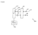
- FIGS. 1 and 2 are diagrams illustrating an LCD 100 , according to the present invention, operating in the reflective and transmissive mode, respectively.
- the LCD 100 includes a liquid crystal cell 102 ; a tunable mirror 104 behind the cell; a backlight 106 which is located behind the tunable mirror 104 ; a first polarizer 108 in front of the cell 102 ; a second polarizer 110 between the cell 102 and the tunable mirror 104 ; a control 118 for the tunable mirror 104 ; and a control 120 for the backlight 106 .
- the liquid crystal cell 102 may be a Supertwisted-Nematic (STN) cell, an Active Matrix Twisted-Nematic (TN) cell or a Passive TN cell.
- STN Supertwisted-Nematic
- TN Active Matrix Twisted-Nematic
- Passive TN cell The construction of the liquid crystal cell typically includes a liquid crystal layer sandwiched between a pair of segmented electrodes.
- the cell 102 can be either in an ON (light emitting) state or an OFF state, wherein voltage is applied across the electrodes of the cell in the OFF state and no voltage is applied across the cell in the ON state.
- the first and second polarizers 108 and 110 are oriented such that when the cell is in the ON state, light entering through one polarizer is rotated upon transmission through the cell, such that the polarization direction is approximately parallel to the transmission axis of the other polarizer, and exits through that polarizer.
- the polarizers When the cell is in the OFF state, light entering through one polarizer is rotated by the cell, such that the polarization direction is approximately orthogonal to the transmission axis of the other polarizer, and is therefore blocked or absorbed by that polarizer.
- the polarizers In the example of a 90° TN cell operating in the normally white mode where the cell rotates light by 90° in the ON state, the polarizers have mutually orthogonal planes of polarization.
- the planes of polarization may not be orthogonal.
- a normally black mode may also be used, in which the voltage is applied in the ON state and no voltage in the OFF state.
- the polarizers are parallel (For a reference on STN cells see T. J. Scheffer and J. Nehring, “Supertwisted Nematic LCDs,” Society for Information Display Seminar Lecture Notes, Vol. 1, M-12, May 15, 2000, and the references therein.)
- the tunable mirror 104 can be switched between reflective and transmissive modes, for primarily reflecting or primarily transmitting light, respectively. More detailed examples of tunable mirrors will be described below.
- the backlight 106 can be switched between emissive and non-emissive states of operation, for emitting light in its emissive state when ambient light entering the liquid crystal cell from the opposite side is too low, and is therefore below a “viewability threshold”.
- emissive and non-emissive states of operation for emitting light in its emissive state when ambient light entering the liquid crystal cell from the opposite side is too low, and is therefore below a “viewability threshold”.
- liquid crystal cell 102 While the liquid crystal cell 102 , tunable mirror 104 , polarizers 108 and 110 are illustrated as being separated, this is for convenience of illustration; in practice these elements would normally be bonded together with adhesives having compensatory indices of refraction.
- the construction of these individual elements is well known in the LCD art. For example, see Okumara, (U.S. Pat. No. 6,008,871); and transflective LCD units having these components (with a partially-reflective partially-transmissive mirror) are sold by companies such as Seiko-Epson and Optrex.
- compensation films which can be located on each side of the liquid crystal cell 102 , and are used with an STN cell. Such elements are well known.
- a light diffusing element may be added to produce a diffused image.
- Such light diffusing element can be made of embossed plastic plate, or a plastic plate dispersed with beads.
- diffusing beads can be mixed into one of the adhesive layers adjacent to any of the above-described elements (See Okumura).
- the backlight is switched to the emissive state when operating in a transmissive mode.
- both the backlight and tunable mirror need to be controlled.
- the mirror and backlight controls 118 and 120 can be either manually set by the user or automatically responsive to the level of ambient light. The user may also be given the option of setting the controls at either manual or automatic ambient light responsive modes.
- an ambient light sensor can be used to switch the backlight to its emissive state and set the mirror in its transmissive mode at low ambient light, and at high ambient light, switch the backlight to its non-emissive state and set the mirror in its reflective mode, for example.
- the two controls 118 and 120 may either operate independently of each other, or in tandem. Where both controls are operated by applying a source of electrical potential, two control circuits operating in series or parallel may be utilized.
- FIG. 1 illustrates the operation of the LCD 100 in the reflective mode in which there is high ambient light, and the tunable mirror 104 is switched to operate in the reflective mode, indicated by the shading 128 . Additionally, the backlight 106 is switched to the non-emissive state of operation 129 .
- the liquid crystal cell 102 is assumed to be a 90° TN cell operating in a normally white mode, and in its ON state, wherein it rotates the plane of polarization of linearly polarized light by 90°.
- polarizers 108 , 110 have mutually orthogonal planes of polarization in the vertical and horizontal directions, respectively.
- the light then travels through the liquid crystal cell 102 , where it is rotated to have a plane of polarization approximately parallel to the transmission axis of the second polarizer, indicated by the dot 134 representing a light vector coming out of the plane of the paper.
- the light then passes through the second polarizer 110 , maintaining its linear polarization 136 , and is primarily reflected by the tunable mirror 128 .
- the reflected light then follows a reversed path with successive polarizations 138 , 140 , 142 and 144 , to emerge as an LCD output 145 .
- the light entering through the first polarizer 108 travels through the cell 102 , where it is rotated to have a plane of polarization approximately orthogonal to the transmission axis of the second polarizer and is blocked.
- FIG. 2 illustrates the operation of the LCD 100 in the transmissive mode, in which the tunable mirror 104 is switched to operate in the transmissive mode, indicated by the absence of shading 200 . Additionally, the backlight 106 is switched to the emissive state of operation 204 . As in the description of FIG. 1, the liquid crystal cell 102 is again assumed to rotate the plane of polarization of linearly polarized light by 90°. First, randomly polarized backlight emission 202 , indicated by unpolarized light vectors 206 , is primarily transmitted through the tunable mirror 104 . The resultant unpolarized light, indicated by vector 208 , then travels through the second polarizer 110 and is linearly polarized 210 .
- a tunable mirror is defined as any device having a controllable transmission and reflection. This includes a transmission/reflection which can be switched among either discrete or continuous states.
- An electro-optic device is one whose optical properties change with an electric signal. This invention contemplates the use of any electro-optic or other device which acts as a tunable mirror for a transflective LCD.
- Tench discloses a suitable reversible electrochemical mirror (REM) having controllable reflective and transmissive modes.
- the REM can be controlled by applying a source of electrical potential which has reversible polarity and adjustable potential.
- the REM takes about 1 second to switch between reflective and transmissive modes.
- the REM may have a matte surface to produce a diffused reflectance.
- the REM can achieve a transmittance of up to 60% due to light absorption, and therefore has limited efficiency.
- tunable mirrors may be constructed by combining a plurality of optical elements, at least one of which is an electro-optic device having switchable optical properties.
- FIGS. 3-17 illustrate examples of such tunable mirrors, and LCDs incorporating these mirrors, according to this invention.
- FIGS. 3-6 illustrate a first tunable mirror assembly 300 , and an LCD 500 incorporating the tunable mirror 300 .
- the tunable mirror 300 includes a switchable cholesteric liquid crystal reflector 302 with a quarter-wave ( ⁇ /4) retarder 304 and a control 305 for the liquid crystal reflector 302 .
- the liquid crystal reflector 302 is controllably switchable between reflecting and transmitting states of operation, for reflecting circularly polarized light of a particular rotational direction in the reflecting state, and for transmitting light in the transmitting state.
- Such Cholesteric liquid crystal devices are commercially available from Kent Displays and Advanced Display Systems (ADS).
- the cholesteric liquid crystal reflector 302 should be custom designed to have a single addressing pixel, which has the same dimensions as the overall LCD.
- Such liquid crystal reflector has a diffuse reflectance in the reflecting state and thus will produce a diffused image without the addition of a light diffusing element.
- a voltage approximately between 20 and 80 Volts
- the reflector 302 changes from a homeotropic state, in which light is transmitted without a change in polarization.
- the ⁇ /4 retarder 304 is an element used for conversion of light between circular and linear polarization forms. It converts horizontal or vertical linearly polarized light to right-handed or left-handed circularly polarized light, depending on the orientation. Conversely, it will convert right-handed or left-handed circularly polarized light to linearly polarized light, and is substantially transmissive to randomly polarized light.
- Such ⁇ /4 retarder can be either birefringent crystal or oriented polymer film and are manufactured by Fuji Film, Nitto Denko, and Meadowlark Optics. (For a reference see Polarization Manipulation with Retarders, Meadowlark Optics, Product Catalogue, 1999-2000).
- liquid crystal reflector 302 and ⁇ /4 retarder 304 are oriented with respect to each other such that in the reflective mode, the reflector 302 reflects light received from the retarder 304 .
- the liquid crystal reflector 302 and ⁇ /4 retarder 304 are illustrated as being separated, however, as components of an LCD, these elements would normally be bonded together.
- FIG. 3 illustrates the operation of the tunable mirror 300 in the reflective mode in which the liquid crystal reflector 302 is in the reflecting state.
- the liquid crystal reflector 302 is capable of reflecting circularly polarized light of one particular rotational direction, e.g. right handed circular polarization but not left handed, indicated by the circular reflection vector 306 .
- linearly polarized light 308 (e.g. in the horizontal direction), as indicated by the polarized light vector 312 , is converted by the ⁇ /4 retarder 304 to a circular right handed polarization, indicated by the polarized light vector 314 .
- the light is then reflected by the liquid crystal reflector 302 , maintaining its circular right handed polarization 316 , and travels back through the ⁇ /4 retarder 304 which converts it back to a horizontal linear polarization 318 .
- FIG. 4 illustrates the operation of the tunable mirror 300 in the transmissive mode, in which the liquid crystal reflector 302 is in the transmitting state.
- the liquid crystal reflector In this state the liquid crystal reflector is transmits light, as indicated by the absence of a reflection vector 400 .
- Randomly polarized light 402 indicated by the unpolarized light vectors 404 , is transmitted through both the liquid crystal reflector 302 and ⁇ /4 retarder 304 , maintaining its random polarization indicated by vectors 406 and 408 .
- FIGS. 5 and 6 illustrate the operation of the LCD 500 which incorporates the tunable mirror 300 .
- the elements of the LCD 500 are essentially the same as those in the previous figures, with the exception of the tunable mirror, and tunable mirror control. These elements are a liquid crystal cell 502 located in front of the ⁇ /4 retarder 304 of the tunable mirror 300 ; a backlight 506 which is located behind the liquid crystal reflector 302 of tunable mirror 300 and can be switched between emissive and non-emissive states; a first polarizer 508 in front of the cell 502 ; a second polarizer 510 between the cell 502 and the ⁇ /4 retarder 304 ; and a control 520 for the backlight 506 .
- the liquid crystal cell 502 is assumed to be a 90° TN cell operating in the normally white mode, and in its ON state wherein it rotates the plane of polarization of linearly polarized light by 90°.
- the first and second polarizers 508 and 510 have mutually orthogonal planes of polarization in the vertical and horizontal directions, respectively.
- FIG. 5 illustrates the LCD 500 operating in the reflective mode, in which the liquid crystal reflector 302 is in the reflecting state, as indicated by the circular reflection vector 306 , and the backlight 506 is in the non-emissive state 526 .
- First, randomly polarized ambient light 526 indicated by unpolarized light vectors 530 , travels through the first polarizer 508 , where it is linearly polarized, as indicated by the polarized light vector 532 .
- the light then travels through the liquid crystal cell 502 , where its is rotated to have a plane of polarization approximately parallel to the transmission axis of the second polarizer, as indicated by the polarized light vector 534 and through the second polarizer 510 , maintaining its linear polarization 536 .
- the light then passes through the ⁇ /4 retarder 304 wherein it is circularly polarized in the right handed direction 538 .
- the circularly polarized light 538 is then reflected by liquid crystal reflector 302 , following a reversed path with successive polarizations 540 , 542 , 544 , 546 , and 548 to emerge as an LCD output 550 .
- the liquid crystal cell 502 is in the OFF state, the light entering through the first polarizer 508 travels through the cell 502 , where it is rotated to have a plane of polarization approximately orthogonal to the transmission axis of the second polarizer 510 and is blocked.
- FIG. 6 illustrates the LCD 500 operating in the transmissive mode, in which the liquid crystal reflector is in the transmitting state, as indicated by the absence of a reflection vector 400 , and the backlight is in its emissive state 600 .
- First, randomly polarized backlight 602 is transmitted through the liquid crystal reflector 302 and ⁇ /4 retarder 304 , having unpolarized light vectors 607 and 608 .
- the resultant light then travels through the second polarizer 510 and is linearly polarized 610 . Its polarization is then rotated by the liquid crystal cell 502 to an approximately linear polarization 612 , parallel to the transmitting axis of the first polarizer 508 .
- the light passes through the first polarizer 508 with linear polarization 614 , to emerge as the LCD output 616 .
- the liquid crystal cell 502 When the liquid crystal cell 502 is in the OFF state, the light exiting the cell 502 has a polarization direction orthogonal to the transmitting axis of the first polarizer 508 and is blocked.
- FIGS. 7-12 illustrate a second tunable mirror assembly 700 , and LCDs 900 , 1100 and 1200 incorporating the tunable mirror 700 .
- the tunable mirror 700 includes a reflective polarizer 702 , a tunable liquid crystal zero to half-wave (0- ⁇ /2) retarder 704 , and a control 705 for the 0- ⁇ /2 retarder 704 .
- the reflective polarizer 702 reflects linearly polarized light of one direction, (e.g. the horizontal direction) and transmits linearly polarized light of another direction (e.g. the vertical direction).
- Commercially available reflective polarizers supplied through Merck and 3M have a specular rather then a diffuse reflectance.
- the 0- ⁇ /2 retarder 704 is controllably switchable between 0 ⁇ and ⁇ /2 states of operation, for rotating the plane of polarization of linearly polarized light by 90° in the ⁇ /2 state, and for transmitting light with no change in the 0 ⁇ state.
- Such retarder is typically of a nematic type, and is switchable to the 0 ⁇ state with the application of a voltage (approximately 10V) at a speed of 20 ms, and works in analogue mode.
- the reflective polarizer 702 and retarder 704 are oriented with respect to each other such that in the reflective mode, the reflective polarizer 702 reflects light received from the retarder 704 , as illustrated in FIGS. 7-12. Also, in FIGS. 7-12, the reflective polarizer 702 and retarder 704 are illustrated as being separated, however, as components of an LCD, these elements would normally be bonded together. Additionally, in an LCD where a diffuse reflectance is desired, an additional light diffusing element may be added with this type of tunable mirror. In this case it is preferable to use a holographic diffuser that does not scramble the polarization.
- FIG. 7 illustrates the operation of the tunable mirror 700 in the reflective mode, in which the 0- ⁇ /2 retarder 704 is in the 0 ⁇ state 708 .
- light having horizontal linear polarization 710 as indicated by the polarized light vector 712 is transmitted through the retarder 704 and reflected by the reflective polarizer 702 , back through the retarder 704 , having successive polarizations 714 , 716 , and 718 .
- the light entering it is also possible for the light entering to have both vertical and linear polarization components. In this case, still only the component having horizontal linear polarization will be reflected back.
- FIG. 8 illustrates the operation of the tunable mirror 700 in the transmissive mode in which the retarder 704 is in the ⁇ /2 state 800 .
- randomly polarized light 802 is transmitted through the reflective polarizer 702 , wherein only the vertical component is transmitted, as indicated by the polarized light vector 806 .
- the light passes through the retarder, wherein its polarization is rotated 90°, as indicated by polarized light vector 808 .
- FIGS. 9 and 10 illustrate the operation of the LCD 900 which incorporates the tunable mirror 700 .
- the elements of the LCD 900 are essentially the same as those in the previous figures, with the exception of the tunable mirror, and tunable mirror control. These elements are a liquid crystal cell 902 located in front of the 0- ⁇ /2 retarder 704 of the tunable mirror 700 ; a backlight 906 which is located behind the reflective polarizer 702 of tunable mirror 700 and can be switched between emissive and non-emissive states of operation; a first polarizer 908 in front of the cell 902 ; a second polarizer 910 between the cell 902 and the retarder 704 ; and a control 920 for the backlight 906 .
- liquid crystal cell 902 is assumed to be a 90° TN cell operating in a normally white mode, and in its ON state, wherein it rotates the plane of polarization of linearly polarized light by 90°.
- first and second polarizers 908 and 910 have mutually orthogonal planes of polarization in the vertical and horizontal directions, respectively.
- FIG. 9 illustrates the LCD 900 operating in the reflective mode, in which the retarder 704 is in the 0 ⁇ state 708 , and the backlight 906 is in its non-emissive state 926 .
- First, randomly polarized ambient light 928 travels through the first polarizer 908 , where it is linearly polarized, as indicated by the polarized light vector 932 .
- the light then travels through the liquid crystal cell 902 , where it is rotated to have a plane of polarization approximately parallel to the transmission axis of the second polarizer 910 , as indicated by the polarized light vector 934 , and passes through the second polarizer 910 , maintaining its linear polarization 936 .
- the light is then transmitted through the 0- ⁇ /2 retarder 704 maintaining its linear polarization 938 , and is reflected back by the reflective polarizer 702 .
- the light then follows a reversed path with successive polarizations 940 , 942 , 944 , 946 , and 948 to emerge as an LCD output 950 .
- the liquid crystal cell 902 is in its OFF state, the light entering through the first polarizer 908 travels through the cell 902 , where it is rotated to have a plane of polarization approximately orthogonal to the transmission axis of the second polarizer 910 , and is blocked.
- FIG. 10 illustrates the LCD 900 operating in the transmissive mode, in which the 0- ⁇ /2 retarder 704 is in the ⁇ /2 state 800 , and the backlight 906 is in the emissive state 1000 .
- the light passes through the retarder 704 wherein its polarization is rotated 90°, as indicated by polarized light vector 1008 .
- the light then passes through the second polarizer 910 maintaining its linear polarization 1010 .
- FIG. 11 illustrates an LCD 1100 , similar to the LCD 900 in which a ⁇ /4 retarder 1102 is located between the backlight 906 and reflective polarizer 702 .
- a ⁇ /4 retarder 1120 between a backlight 906 and a reflective polarizer 702 can improve the brightness of the display. This is because horizontally polarized light not transmitted by the reflective polarizer 702 in the transmissive mode is reflected back through the ⁇ /4 retarder 1120 . The light is then circularly polarized in the right handed rotational direction, and is reflected back through the retarder as left handed circularly polarized light. The light then emerges through the retarder 1120 with vertical linear polarization, and passes through the reflective polarizer 702 . (See Taber, U.S. Pat. No. 5,731,886).
- FIG. 12 illustrates this LCD assembly 1200 .
- FIGS. 13-17 illustrate a third tunable mirror assembly 1300 , and LCDs 1500 and 1700 incorporating the tunable mirror 1300 .
- the tunable mirror 1300 includes a cholesteric reflector 1302 , a negative quarter-wave to positive quarter-wave (+/ ⁇ /4) liquid crystal retarder 1304 , and a control 1306 for the +/ ⁇ /4 retarder.
- the cholesteric reflector 1302 reflects circularly polarized light having a polarization of one rotational direction, and transmits circularly polarized light of the opposite rotational direction.
- the cholesteric reflector 1302 may be a diffuse reflecting cholesteric liquid crystal polymer film, which diffuses light.
- Such reflector may be made according to the process described in Wacker-Chemie, R. Maurer, F. H. Kreuzer, and J. Stohrer, “Cholesteric Reflectors with a Color Pattern”, SID 94 Digest, p. 399 (1994).
- the +/ ⁇ /4 retarder functions similarly to the ⁇ /4 retarder in that it converts light between circular and linear polarization forms.
- the +/ ⁇ /4 retarder 1304 is controllably switchable between ⁇ /4 and + ⁇ /4 states of operation, wherein the optical phase delay between the two states differs by half a wavelength ( ⁇ /2).
- the retarder 1304 converts horizontal or vertical linearly polarized light to right-handed or left-handed circularly polarized light, respectively. Conversely, it will convert right-handed or left handed circularly polarized light to horizontal or vertical linearly polarized light, respectively.
- the retarder 1304 converts horizontal or vertical linearly polarized light to left-handed or right-handed circularly polarized light, respectively, and conversely, it will convert right-handed or left handed circularly polarized light to vertical or horizontal linearly polarized light, respectively.
- Such retarder can be either of a nematic or ferroelectric type.
- the nematic type can be made by combining a ⁇ /4 retarder with a 0 ⁇ /2 wave retarder.
- This invention contemplates the use of any suitable retarder which can be controllably switched between two states, with the optical phase delay between the two states differing by ⁇ /2.
- the cholesteric reflector 1303 and retarder 1304 are oriented with respect to each other such that in the reflective mode, the cholesteric reflector 1302 reflects light received from the retarder 1304 , as illustrated in FIGS. 13-17. Also, in FIGS. 13-17, the cholesteric reflector 1302 and +/ ⁇ /4 retarder 1304 are illustrated as being separated, however, as components of an LCD, these elements would normally be bonded together.
- FIG. 13 illustrates the operation of the tunable mirror 1300 in the reflective mode, in which the retarder 1304 is in the + ⁇ /4 state 1308 , for converting horizontal linearly polarized light to circularly polarized light of a right rotational direction.
- the cholesteric reflector reflects right handed circularly polarized light and transmits left handed circularly polarized light.
- light having horizontal linear polarization 1312 as indicated by the polarized light vector 1314 is transmitted through the retarder 1304 and converted to right handed circularly polarized light, as indicated by polarization vector 1316 .
- the light is then reflected by the cholesteric reflector 1302 , maintaining its polarization 1318 , and is then linearly polarized back through the retarder 1304 , to its original horizontal polarization 1320 . It is also possible for the light entering to have both horizontal and vertical polarizations. In this case, still only the component having horizontal linear polarization will be converted into circularly right handed polarization and reflected back.
- FIG. 14 illustrates the operation of the tunable mirror 1300 in the transmissive mode, in which the +/ ⁇ /4 retarder 1304 is in the ⁇ /4 state 1400 .
- randomly polarized light 1402 is transmitted through the cholesteric reflector 1302 , wherein only the left handed circularly polarized component is transmitted, as indicated by the polarized light vector 1406 .
- the light passes through the retarder 1304 wherein it is linearly polarized to a horizontal linear polarization 1408 .
- FIGS. 15 and 16 illustrate the operation of the LCD 1500 which incorporates the tunable mirror 1300 .
- the elements of the LCD 1500 are essentially the same as those in the previous figures, with the exception of the tunable mirror and tunable mirror control. These elements are a liquid crystal cell 1502 located in front of the +/ ⁇ /4 retarder 1304 of the tunable mirror 1300 ; a backlight 1506 which is located behind the cholesteric reflector 1302 of tunable mirror 1300 and can be switched between emissive and non-emissive states; a first polarizer 1508 in front of the cell 1502 ; a second polarizer 1510 between the cell 1502 and the +/ ⁇ /4 retarder 1304 ; and a control 1520 for the backlight 1506 .
- liquid crystal cell 1502 is assumed to be a 90° TN cell operating in a normally white mode, and in its ON state wherein it rotates the plane of polarization of linearly polarized light by 90°.
- first and second polarizers 1508 and 1510 have mutually orthogonal planes of polarization 1522 and 1524 in the vertical and horizontal directions, respectively.
- FIG. 15 illustrates the LCD 1500 operating in the reflective mode, in which the +/ ⁇ /4 retarder 1304 is in the + ⁇ /4 state 1308 , and the backlight 1506 is in the non-emissive state 1526 .
- First, randomly polarized ambient light 1528 indicated by unpolarized light vectors 1530 , travels through the first polarizer 1508 , and is linearly polarized, as indicated by the polarized light vector 1532 .
- the light then travels through the liquid crystal cell 1502 , where it is rotated (approximately 90°) to have a plane of polarization approximately parallel to the transmission axis of the second polarizer, as indicated by the polarized light vector 1534 , and then passes through the second polarizer 1510 , maintaining its linear polarization 1536 .
- the light is then transmitted through the retarder 1304 and is circularly polarized in the right handed direction, as indicated by polarization vector 1538 . Thereafter, the light is reflected back by the cholesteric reflector 1302 .
- the light then follows a reversed path with successive polarizations 1540 , 1542 , 1544 , 1546 , and 1548 to emerge as an LCD output 1550 .
- the light entering through the first polarizer 1508 travels through the cell 1502 , where it is rotated to have a plane of polarization approximately orthogonal to the transmission axis of the second polarizer 1510 and is blocked.
- FIG. 16 illustrates the LCD 1500 operating in the reflective mode, in which the retarder 1304 is in the ⁇ /4 state 1400 , and the backlight 1506 is in the emissive state 1600 .
- the light passes through the retarder 1304 wherein it is linearly polarized to a horizontal linear polarization 1608 .
- the light then passes through the second polarizer 1510 maintaining its linear polarization 1610 .
- FIG. 17 illustrates this LCD assembly 1700 .
- the LCD and tunable mirror may optionally include an intermediate mode of operation, in which the tunable mirror and backlight are operated at intermediate states.
- An LCD with a tunable mirror may be incorporated into many types of operating systems, including but not limited to: Global Positioning Satellite (GPS) receiver units; computers including the laptop and notepad units; personal digital assistants; calculators; personal calendars; cellular telephones; watches and clocks; automobile, aircraft, and boat displays.
- GPS Global Positioning Satellite
- FIGS. 18 a - 18 c Three examples of operating systems embodying the present invention are shown in FIGS. 18 a - 18 c .
- FIG. 18 a is a cellular telephone 1800 with an LCD 1802 , according to the present invention.
- FIG. 18 b is a watch 1804 with an LCD 1806 , according to the present invention
- FIG. 18 c is a laptop 1808 with an LCD screen 1810 according to the present invention, attached to the keypad section 1812 . Since cellular telephones, watches and laptops can be battery operated, using an LCD in accordance with the present invention is desirable as it saves battery life, as well as increase the contrast and brightness of the display.
Abstract
Description
Claims (6)
Priority Applications (6)
| Application Number | Priority Date | Filing Date | Title |
|---|---|---|---|
| US09/676,138 US6710831B1 (en) | 2000-09-29 | 2000-09-29 | High brightness transflective LCD and method using tunable mirror |
| AU2001291187A AU2001291187A1 (en) | 2000-09-29 | 2001-09-21 | High brightness transflective lcd and method using tunable mirror |
| JP2002532996A JP2004522983A (en) | 2000-09-29 | 2001-09-21 | How to use high brightness partially transmissive LCD and tunable mirror |
| PCT/US2001/029610 WO2002029484A2 (en) | 2000-09-29 | 2001-09-21 | High brightness transflective lcd and method using tunable mirror |
| EP01971286A EP1322996A2 (en) | 2000-09-29 | 2001-09-21 | High brightness transflective lcd and method using tunable mirror |
| KR1020037004224A KR100695186B1 (en) | 2000-09-29 | 2001-09-21 | High brightness transflective lcd and method using tunable mirror |
Applications Claiming Priority (1)
| Application Number | Priority Date | Filing Date | Title |
|---|---|---|---|
| US09/676,138 US6710831B1 (en) | 2000-09-29 | 2000-09-29 | High brightness transflective LCD and method using tunable mirror |
Publications (1)
| Publication Number | Publication Date |
|---|---|
| US6710831B1 true US6710831B1 (en) | 2004-03-23 |
Family
ID=24713370
Family Applications (1)
| Application Number | Title | Priority Date | Filing Date |
|---|---|---|---|
| US09/676,138 Expired - Lifetime US6710831B1 (en) | 2000-09-29 | 2000-09-29 | High brightness transflective LCD and method using tunable mirror |
Country Status (6)
| Country | Link |
|---|---|
| US (1) | US6710831B1 (en) |
| EP (1) | EP1322996A2 (en) |
| JP (1) | JP2004522983A (en) |
| KR (1) | KR100695186B1 (en) |
| AU (1) | AU2001291187A1 (en) |
| WO (1) | WO2002029484A2 (en) |
Cited By (30)
| Publication number | Priority date | Publication date | Assignee | Title |
|---|---|---|---|---|
| US20040075797A1 (en) * | 2002-10-17 | 2004-04-22 | Xinyu Zhu | Broadband quarter-wave films |
| US20040140772A1 (en) * | 2003-01-21 | 2004-07-22 | Geraldo Gullo | System and process for providing a display arrangement on a device that may be limited by an intrinsic safety barrier |
| US20040207609A1 (en) * | 2003-03-05 | 2004-10-21 | Ryouta Hata | Display method, display controller, and display apparatus |
| WO2006038192A2 (en) * | 2004-10-08 | 2006-04-13 | Koninklijke Philips Electronics N.V. | Transflective liquid crystal display device |
| EP1666961A1 (en) * | 2004-12-02 | 2006-06-07 | NEC Corporation | Transflective liquid crystal display device and electronic device equipped with the same |
| US20070132914A1 (en) * | 2003-10-23 | 2007-06-14 | Nitto Denko Corporation | Optical element, light condensation backlight system, and liquid crystal display |
| US20070139772A1 (en) * | 2005-12-21 | 2007-06-21 | Xinghua Wang | Optical birefringence filters with interleaved absorptive and zero degree reflective polarizers |
| US20070153157A1 (en) * | 2005-12-30 | 2007-07-05 | Hee Kwang Kang | Liquid crystal display device and method for driving the same |
| US20070226094A1 (en) * | 2004-12-01 | 2007-09-27 | Malackowski James E | System and method for using intellectual property holding companies to validate the market value of intellectual property and provide investment opportunities |
| US20070263147A1 (en) * | 2006-05-10 | 2007-11-15 | Chi Mei Optoelectronics Corp. | Lcd apparatus and method for enhancing luminance efficiency thereof |
| US20090021672A1 (en) * | 2007-07-20 | 2009-01-22 | Au Optronics Corporation | Display apparatus |
| US20100186032A1 (en) * | 2009-01-21 | 2010-07-22 | Neurofocus, Inc. | Methods and apparatus for providing alternate media for video decoders |
| US20100277786A1 (en) * | 2008-07-10 | 2010-11-04 | Gentex Corporation | Rearview Mirror Assemblies With Anisotropic Polymer Laminates |
| CN101995723A (en) * | 2009-08-05 | 2011-03-30 | 乐金显示有限公司 | In-plane switching mode transflective type liquid crystal display device |
| CN101657753B (en) * | 2007-02-16 | 2011-09-21 | 三星电子株式会社 | Liquid crystal display device switchable between reflective mode and transmissive mode by employing active reflective polarizer |
| US20120099250A1 (en) * | 2010-10-22 | 2012-04-26 | Robinson Ian N | Display with rotatable display screen |
| US20120287510A1 (en) * | 2011-05-12 | 2012-11-15 | Delphi Technologies, Inc. | Transreflective vehicle mirror system |
| US8545030B2 (en) | 2004-07-12 | 2013-10-01 | Gentex Corporation | Rearview mirror assemblies with anisotropic polymer laminates |
| US20140132898A1 (en) * | 2012-11-12 | 2014-05-15 | Boe Technology Group Co., Ltd. | Display panel and display device |
| US20140267203A1 (en) * | 2013-03-18 | 2014-09-18 | Venkataraman Ramanathan | Glare reduction system |
| US8977110B2 (en) | 2009-01-21 | 2015-03-10 | The Nielsen Company (Us), Llc | Methods and apparatus for providing video with embedded media |
| US20160247319A1 (en) * | 2015-02-20 | 2016-08-25 | Andreas G. Nowatzyk | Selective occlusion system for augmented reality devices |
| US9448449B2 (en) | 2013-01-31 | 2016-09-20 | Venkataraman Ramanathan | Glare reduction system |
| US9581858B2 (en) | 2013-12-23 | 2017-02-28 | Samsung Display Co., Ltd. | Mirror display device |
| US9709848B2 (en) | 2015-04-17 | 2017-07-18 | Amel Technology, Llc | Transflective liquid crystal display |
| EP3273482A1 (en) * | 2016-07-19 | 2018-01-24 | Samsung Display Co., Ltd. | Display apparatus |
| TWI670545B (en) * | 2014-07-04 | 2019-09-01 | 瑞士商史華曲集團研發有限公司 | Display assembly including two superposed display devices |
| US10746906B2 (en) * | 2016-01-29 | 2020-08-18 | Fujifilm Corporation | Half mirror and mirror with image display function |
| US20200387015A1 (en) * | 2019-06-10 | 2020-12-10 | Viavi Solutions Inc. | Polarization scrambler using a retardance element |
| CN114460774A (en) * | 2021-12-10 | 2022-05-10 | 中国科学院重庆绿色智能技术研究院 | Reflection type geometric phase liquid crystal spatial light modulation method, system and storage medium |
Families Citing this family (11)
| Publication number | Priority date | Publication date | Assignee | Title |
|---|---|---|---|---|
| GB2383641A (en) * | 2001-12-21 | 2003-07-02 | Nokia Corp | Reflective displays |
| DE10233734A1 (en) * | 2002-07-24 | 2004-02-05 | Siemens Ag | Mirror with display device especially for motor vehicles has a liquid crystal cell with rear polarized foil and a front polarizing filter |
| DE10260297A1 (en) * | 2002-12-20 | 2004-07-01 | Siemens Ag | Display device for an electrical device |
| GB2397894B (en) * | 2003-02-03 | 2006-05-03 | Samsung Electronics Co Ltd | Improvements in mobile communication devices |
| US6861788B2 (en) * | 2003-06-03 | 2005-03-01 | Motorola, Inc. | Switchable display/mirror method and apparatus |
| KR100946432B1 (en) * | 2008-04-08 | 2010-03-10 | 하이디스 테크놀로지 주식회사 | Automatic holography display device |
| KR102036895B1 (en) | 2013-04-23 | 2019-10-25 | 삼성전자주식회사 | Camera assembly and image acquiring method using the same |
| EP2963505A1 (en) * | 2014-07-04 | 2016-01-06 | The Swatch Group Research and Development Ltd. | Display assembly including two stacked display devices |
| US20160104751A1 (en) * | 2014-10-10 | 2016-04-14 | The Swatch Group Research And Development Ltd | Hybrid display assembly including a solar cell |
| JP6441098B2 (en) * | 2015-02-02 | 2018-12-19 | 日東電工株式会社 | Video display mirror for vehicles |
| KR102640018B1 (en) * | 2018-08-02 | 2024-02-27 | 엘지디스플레이 주식회사 | Display device capable of performing a mirror function |
Citations (20)
| Publication number | Priority date | Publication date | Assignee | Title |
|---|---|---|---|---|
| US4093356A (en) | 1977-02-14 | 1978-06-06 | General Electric Company | Transflective liquid crystal display |
| US4398805A (en) | 1981-07-06 | 1983-08-16 | General Electric Company | Transflective liquid crystal display |
| US5146355A (en) | 1986-10-23 | 1992-09-08 | Litton Systems Canada Limited | Transflective mode liquid crystal display with phosphor illumination |
| US5182663A (en) * | 1991-08-30 | 1993-01-26 | Raychem Corporation | Liquid crystal display having improved retroreflector |
| JPH05203937A (en) * | 1992-01-28 | 1993-08-13 | Seiko Epson Corp | Liquid crystal display device, window glass, and information equipment |
| US5504603A (en) | 1994-04-04 | 1996-04-02 | Rockwell International Corporation | Optical compensator for improved gray scale performance in liquid crystal display |
| WO1997001789A2 (en) | 1995-06-26 | 1997-01-16 | Minnesota Mining And Manufacturing Company | Optical panel capable of switching between reflective and transmissive states |
| US5612801A (en) * | 1994-04-04 | 1997-03-18 | Rockwell Science Center, Inc. | Monolithic optical compensation device for improved viewing angle in liquid crystal displays |
| US5731886A (en) | 1995-09-28 | 1998-03-24 | Rockwell International Corporation | Birefringent compensator for reflective polarizers |
| JPH10206844A (en) | 1997-01-24 | 1998-08-07 | Sharp Corp | Liquid crystal display device |
| US5796454A (en) | 1996-12-04 | 1998-08-18 | Advanced Display Systems, Inc. | Cholesteric liquid crystal display employing circular polarizer and methods of operation and manufacture therefor |
| WO1998038547A1 (en) | 1997-02-26 | 1998-09-03 | Reveo, Inc. | Electro-optical glazing structures having reflection and transparent modes of operation |
| US5808711A (en) | 1997-08-22 | 1998-09-15 | Motorola, Inc. | Transparent or reflective liquid crystal display assembly with electrochromic and cholesteric layer |
| US5923456A (en) | 1997-12-19 | 1999-07-13 | Rockwell International Corporation | Reversible electrochemical mirror |
| US5982465A (en) | 1997-07-11 | 1999-11-09 | Rockwell International Corporation | Film compensated normally white super-twist nematic liquid crystal display that reduces chromaticity shifts over large temperature and viewing angle range |
| US6008871A (en) | 1997-01-20 | 1999-12-28 | Seiko Epson Corporation | Transflective liquid crystal display device having a reflective polarizer |
| US6039451A (en) | 1998-06-04 | 2000-03-21 | Rockwell Science Center, Inc. | Sculptured transflector for dual mode active matrix liquid crystal display backlight |
| JP2000221544A (en) | 1999-01-28 | 2000-08-11 | Samsung Sdi Co Ltd | Liquid crystal display device |
| WO2000063745A2 (en) | 1999-04-20 | 2000-10-26 | Koninklijke Philips Electronics N.V. | Transflective display device |
| US6144359A (en) | 1998-03-30 | 2000-11-07 | Rockwell Science Center | Liquid crystal displays utilizing polymer dispersed liquid crystal devices for enhanced performance and reduced power |
Family Cites Families (1)
| Publication number | Priority date | Publication date | Assignee | Title |
|---|---|---|---|---|
| JP2752309B2 (en) * | 1993-01-19 | 1998-05-18 | 松下電器産業株式会社 | Display device |
-
2000
- 2000-09-29 US US09/676,138 patent/US6710831B1/en not_active Expired - Lifetime
-
2001
- 2001-09-21 AU AU2001291187A patent/AU2001291187A1/en not_active Abandoned
- 2001-09-21 KR KR1020037004224A patent/KR100695186B1/en not_active IP Right Cessation
- 2001-09-21 JP JP2002532996A patent/JP2004522983A/en active Pending
- 2001-09-21 WO PCT/US2001/029610 patent/WO2002029484A2/en not_active Application Discontinuation
- 2001-09-21 EP EP01971286A patent/EP1322996A2/en not_active Withdrawn
Patent Citations (21)
| Publication number | Priority date | Publication date | Assignee | Title |
|---|---|---|---|---|
| US4093356A (en) | 1977-02-14 | 1978-06-06 | General Electric Company | Transflective liquid crystal display |
| US4398805A (en) | 1981-07-06 | 1983-08-16 | General Electric Company | Transflective liquid crystal display |
| US5146355A (en) | 1986-10-23 | 1992-09-08 | Litton Systems Canada Limited | Transflective mode liquid crystal display with phosphor illumination |
| US5182663A (en) * | 1991-08-30 | 1993-01-26 | Raychem Corporation | Liquid crystal display having improved retroreflector |
| JPH05203937A (en) * | 1992-01-28 | 1993-08-13 | Seiko Epson Corp | Liquid crystal display device, window glass, and information equipment |
| US5504603A (en) | 1994-04-04 | 1996-04-02 | Rockwell International Corporation | Optical compensator for improved gray scale performance in liquid crystal display |
| US5612801A (en) * | 1994-04-04 | 1997-03-18 | Rockwell Science Center, Inc. | Monolithic optical compensation device for improved viewing angle in liquid crystal displays |
| WO1997001789A2 (en) | 1995-06-26 | 1997-01-16 | Minnesota Mining And Manufacturing Company | Optical panel capable of switching between reflective and transmissive states |
| US5731886A (en) | 1995-09-28 | 1998-03-24 | Rockwell International Corporation | Birefringent compensator for reflective polarizers |
| US5796454A (en) | 1996-12-04 | 1998-08-18 | Advanced Display Systems, Inc. | Cholesteric liquid crystal display employing circular polarizer and methods of operation and manufacture therefor |
| US6008871A (en) | 1997-01-20 | 1999-12-28 | Seiko Epson Corporation | Transflective liquid crystal display device having a reflective polarizer |
| JPH10206844A (en) | 1997-01-24 | 1998-08-07 | Sharp Corp | Liquid crystal display device |
| WO1998038547A1 (en) | 1997-02-26 | 1998-09-03 | Reveo, Inc. | Electro-optical glazing structures having reflection and transparent modes of operation |
| US5982465A (en) | 1997-07-11 | 1999-11-09 | Rockwell International Corporation | Film compensated normally white super-twist nematic liquid crystal display that reduces chromaticity shifts over large temperature and viewing angle range |
| US5808711A (en) | 1997-08-22 | 1998-09-15 | Motorola, Inc. | Transparent or reflective liquid crystal display assembly with electrochromic and cholesteric layer |
| US5923456A (en) | 1997-12-19 | 1999-07-13 | Rockwell International Corporation | Reversible electrochemical mirror |
| US6144359A (en) | 1998-03-30 | 2000-11-07 | Rockwell Science Center | Liquid crystal displays utilizing polymer dispersed liquid crystal devices for enhanced performance and reduced power |
| US6039451A (en) | 1998-06-04 | 2000-03-21 | Rockwell Science Center, Inc. | Sculptured transflector for dual mode active matrix liquid crystal display backlight |
| JP2000221544A (en) | 1999-01-28 | 2000-08-11 | Samsung Sdi Co Ltd | Liquid crystal display device |
| WO2000063745A2 (en) | 1999-04-20 | 2000-10-26 | Koninklijke Philips Electronics N.V. | Transflective display device |
| US6437900B1 (en) * | 1999-04-20 | 2002-08-20 | Koninklijke Philips Electronics N.V. | Transflective display device |
Non-Patent Citations (16)
| Title |
|---|
| Cholesteric Reflectors With a Color Pattern,Wacker-Chemie Maurer, Kreuzer and Stohrer, SID 94 Digest, p. 399-402. |
| Control of Reflectivity and Bistability in Displays Using Cholesteric Liquid Crystals, Yang, West, Chien and Doane, 1994 American Institute of Physics, p. 1331-1333. |
| Gray Scale and Contrast Compensator for LCDS Using Obliquely Oriented Anisotropic, Taber, Hale, Winker and GunningIII, Skarohlid, Sampica and Seder. |
| Liquid-Crystal Displays, Christopher Booth and Peter Raynes, Jun. 1997. |
| Machine translation of 10-206844 pp. 1-20.* * |
| Polarization Manipulation with Retarders, Meadowlark Optics, p. 5. |
| Polarization Spoken Here, Meadowlark Optics, Nov. 6, 2000. |
| Retarders, Polarization Manipulation with Retarders, Meadowlark Optics, Jul. 20, 2000, p. 1-3. |
| Saji, T., et al., "Short-Term Hemodynamic Effect of a New Oral PGI2 Analogue, Beraprost, in Primary and Secondary Pulmonary Hypertension," Am. J. Cardio. 78:244-247 (1996). |
| Sakoda, T., et al., "Myristoylation of endothelial cell nitric oxide synthase is important for extracellular release of nitric oxide," Mol. Cell. Biochem. 152:143-148 (1995). |
| Sandig, V., and Strauss, M., "Liver-directed gene transfer and application to therapy," J. Mol. Med. 74:205-212 (1996). |
| Seminar M-1, Supertwisted Nematic (STN) LCDS, Scheffer and Nehring, 1994, p. M-1/3-M-1/5. |
| Seminar M-12; Supertwisted-Nematic LCDs, Scheffer and Nehring, p. M-12/3-M12/39. |
| Seminar M-2 Active Matrix LCDS, Robert L. Wisnief, 1994 p. M-2/3 -M-2/5. |
| XP002204574. |
| Zero Field, Multistable Cholesteric Liquid Crystal Displays, Wu, Gao, Ma and Zhou, p. 476-479. |
Cited By (55)
| Publication number | Priority date | Publication date | Assignee | Title |
|---|---|---|---|---|
| US6922221B2 (en) * | 2002-10-17 | 2005-07-26 | Research Foundation Of The University Of Central Florida | Broadband quarter-wave film device including in combination a chromatic half-wave film and a TN-LC polymeric film |
| US20040075797A1 (en) * | 2002-10-17 | 2004-04-22 | Xinyu Zhu | Broadband quarter-wave films |
| US20040140772A1 (en) * | 2003-01-21 | 2004-07-22 | Geraldo Gullo | System and process for providing a display arrangement on a device that may be limited by an intrinsic safety barrier |
| US20040207609A1 (en) * | 2003-03-05 | 2004-10-21 | Ryouta Hata | Display method, display controller, and display apparatus |
| US7397470B2 (en) * | 2003-03-05 | 2008-07-08 | Matsushita Electric Industrial Co., Ltd. | Display method, display controller, and display apparatus |
| US20070132914A1 (en) * | 2003-10-23 | 2007-06-14 | Nitto Denko Corporation | Optical element, light condensation backlight system, and liquid crystal display |
| US7746421B2 (en) * | 2003-10-23 | 2010-06-29 | Nitto Denko Corporation | Optical element, light condensation backlight system, and liquid crystal display |
| US9910310B2 (en) | 2004-07-12 | 2018-03-06 | Gentex Corporation | Variable reflectance mirror system |
| US8545030B2 (en) | 2004-07-12 | 2013-10-01 | Gentex Corporation | Rearview mirror assemblies with anisotropic polymer laminates |
| US10466524B2 (en) | 2004-07-12 | 2019-11-05 | Gentex Corporation | Variable reflectance mirror system |
| WO2006038192A3 (en) * | 2004-10-08 | 2006-11-23 | Koninkl Philips Electronics Nv | Transflective liquid crystal display device |
| WO2006038192A2 (en) * | 2004-10-08 | 2006-04-13 | Koninklijke Philips Electronics N.V. | Transflective liquid crystal display device |
| US20070226094A1 (en) * | 2004-12-01 | 2007-09-27 | Malackowski James E | System and method for using intellectual property holding companies to validate the market value of intellectual property and provide investment opportunities |
| US20060209002A1 (en) * | 2004-12-02 | 2006-09-21 | Nec Corporation | Liquid crystal display device and electronic device equipped therewith |
| EP1666961A1 (en) * | 2004-12-02 | 2006-06-07 | NEC Corporation | Transflective liquid crystal display device and electronic device equipped with the same |
| WO2007076338A3 (en) * | 2005-12-21 | 2009-04-02 | Chemimage Corp | Optical birefringence filters with interleaved absorptive and zero degree reflective polarizers |
| US20070139772A1 (en) * | 2005-12-21 | 2007-06-21 | Xinghua Wang | Optical birefringence filters with interleaved absorptive and zero degree reflective polarizers |
| US7859753B2 (en) | 2005-12-21 | 2010-12-28 | Chem Image Corporation | Optical birefringence filters with interleaved absorptive and zero degree reflective polarizers |
| WO2007076338A2 (en) * | 2005-12-21 | 2007-07-05 | Chemimage Corporation | Optical birefringence filters with interleaved absorptive and zero degree reflective polarizers |
| US20070153157A1 (en) * | 2005-12-30 | 2007-07-05 | Hee Kwang Kang | Liquid crystal display device and method for driving the same |
| US8154504B2 (en) * | 2005-12-30 | 2012-04-10 | Lg Display Co., Ltd. | Liquid crystal display device capable of automatically switching to a mode and method for driving the same |
| US20070263147A1 (en) * | 2006-05-10 | 2007-11-15 | Chi Mei Optoelectronics Corp. | Lcd apparatus and method for enhancing luminance efficiency thereof |
| US8107041B2 (en) * | 2006-05-10 | 2012-01-31 | Chimei Innolux Corporation | LCD apparatus and method for enhancing luminance efficiency thereof with a backlight module generating an elliptically polarized light |
| CN101657753B (en) * | 2007-02-16 | 2011-09-21 | 三星电子株式会社 | Liquid crystal display device switchable between reflective mode and transmissive mode by employing active reflective polarizer |
| US20090021672A1 (en) * | 2007-07-20 | 2009-01-22 | Au Optronics Corporation | Display apparatus |
| US7755724B2 (en) | 2007-07-20 | 2010-07-13 | Au Optronics Corporation | Display apparatus |
| US20100277786A1 (en) * | 2008-07-10 | 2010-11-04 | Gentex Corporation | Rearview Mirror Assemblies With Anisotropic Polymer Laminates |
| US10427606B2 (en) | 2008-07-10 | 2019-10-01 | Gentex Corporation | Rearview mirror assemblies with anisotropic polymer laminates |
| US9357240B2 (en) | 2009-01-21 | 2016-05-31 | The Nielsen Company (Us), Llc | Methods and apparatus for providing alternate media for video decoders |
| US20100186032A1 (en) * | 2009-01-21 | 2010-07-22 | Neurofocus, Inc. | Methods and apparatus for providing alternate media for video decoders |
| US9826284B2 (en) | 2009-01-21 | 2017-11-21 | The Nielsen Company (Us), Llc | Methods and apparatus for providing alternate media for video decoders |
| US8977110B2 (en) | 2009-01-21 | 2015-03-10 | The Nielsen Company (Us), Llc | Methods and apparatus for providing video with embedded media |
| CN101995723A (en) * | 2009-08-05 | 2011-03-30 | 乐金显示有限公司 | In-plane switching mode transflective type liquid crystal display device |
| CN101995723B (en) * | 2009-08-05 | 2012-12-12 | 乐金显示有限公司 | In-plane switching mode transflective type liquid crystal display device |
| US20120099250A1 (en) * | 2010-10-22 | 2012-04-26 | Robinson Ian N | Display with rotatable display screen |
| US8854802B2 (en) * | 2010-10-22 | 2014-10-07 | Hewlett-Packard Development Company, L.P. | Display with rotatable display screen |
| US20120287510A1 (en) * | 2011-05-12 | 2012-11-15 | Delphi Technologies, Inc. | Transreflective vehicle mirror system |
| US20140132898A1 (en) * | 2012-11-12 | 2014-05-15 | Boe Technology Group Co., Ltd. | Display panel and display device |
| US9448449B2 (en) | 2013-01-31 | 2016-09-20 | Venkataraman Ramanathan | Glare reduction system |
| US20140267203A1 (en) * | 2013-03-18 | 2014-09-18 | Venkataraman Ramanathan | Glare reduction system |
| US9601083B2 (en) * | 2013-03-18 | 2017-03-21 | Venkataraman Ramanathan | Glare reduction system |
| US9581858B2 (en) | 2013-12-23 | 2017-02-28 | Samsung Display Co., Ltd. | Mirror display device |
| TWI670545B (en) * | 2014-07-04 | 2019-09-01 | 瑞士商史華曲集團研發有限公司 | Display assembly including two superposed display devices |
| US20160247319A1 (en) * | 2015-02-20 | 2016-08-25 | Andreas G. Nowatzyk | Selective occlusion system for augmented reality devices |
| US11468639B2 (en) * | 2015-02-20 | 2022-10-11 | Microsoft Technology Licensing, Llc | Selective occlusion system for augmented reality devices |
| US9709848B2 (en) | 2015-04-17 | 2017-07-18 | Amel Technology, Llc | Transflective liquid crystal display |
| US10746906B2 (en) * | 2016-01-29 | 2020-08-18 | Fujifilm Corporation | Half mirror and mirror with image display function |
| US11004913B2 (en) | 2016-07-19 | 2021-05-11 | Samsung Display Co., Ltd. | Display apparatus |
| US10580838B2 (en) | 2016-07-19 | 2020-03-03 | Samsung Display Co., Ltd. | Display apparatus |
| EP3273482A1 (en) * | 2016-07-19 | 2018-01-24 | Samsung Display Co., Ltd. | Display apparatus |
| US20200387015A1 (en) * | 2019-06-10 | 2020-12-10 | Viavi Solutions Inc. | Polarization scrambler using a retardance element |
| US11526035B2 (en) * | 2019-06-10 | 2022-12-13 | Viavi Solutions Inc. | Polarization scrambler using a retardance element |
| US11754862B2 (en) | 2019-06-10 | 2023-09-12 | Viavi Solutions Inc. | Polarization scrambler using a retardance element |
| CN114460774A (en) * | 2021-12-10 | 2022-05-10 | 中国科学院重庆绿色智能技术研究院 | Reflection type geometric phase liquid crystal spatial light modulation method, system and storage medium |
| CN114460774B (en) * | 2021-12-10 | 2024-01-09 | 中国科学院重庆绿色智能技术研究院 | Reflective geometric phase liquid crystal spatial light modulation method, system and storage medium |
Also Published As
| Publication number | Publication date |
|---|---|
| KR20040019257A (en) | 2004-03-05 |
| WO2002029484A2 (en) | 2002-04-11 |
| JP2004522983A (en) | 2004-07-29 |
| AU2001291187A1 (en) | 2002-04-15 |
| KR100695186B1 (en) | 2007-03-19 |
| WO2002029484A3 (en) | 2003-01-09 |
| EP1322996A2 (en) | 2003-07-02 |
Similar Documents
| Publication | Publication Date | Title |
|---|---|---|
| US6710831B1 (en) | High brightness transflective LCD and method using tunable mirror | |
| US6344887B1 (en) | Full spectrum reflective choleterics display employing circular polarizers with the same polarity but different disposition | |
| US6757039B2 (en) | Paper white cholesteric displays employing reflective elliptical polarizer | |
| US6317180B1 (en) | Liquid crystal device and electronic apparatus using the same having two absorptive polarizers, a reflective polarizer, and a backlight | |
| US6160595A (en) | Liquid crystal display with edge-lit backlight which uses ambient light injected between reflector and cholesteric polarizer | |
| US6853413B2 (en) | Polarized display with wide-angle illumination | |
| US20030081151A1 (en) | Display device, electronic apparatus using the same and light guider for display devices | |
| US6507380B1 (en) | Display device and electronic apparatus using the same | |
| US7446835B2 (en) | Transflective switchable double-cell LCD device | |
| AU2001251596A1 (en) | Polarized display with wide-angle illumination | |
| EP1449024A2 (en) | Transflective liquid crystal display | |
| JP2000131681A (en) | Semi-transmission type liquid crystal display device | |
| WO2002099525A1 (en) | Reverse-mode direct-view display employing a liquid crystal having a non-visible characteristic wavelength | |
| US20050206811A1 (en) | Novel optical configurations in high contrast chiral nematic liquid crystal displays | |
| JPH11298026A (en) | Solar cell and electronic device using the same | |
| JP3233649B2 (en) | Liquid crystal display device and electronic device using the same | |
| JPH1164840A (en) | Liquid crystal display device | |
| JP2000066193A (en) | Liquid crystal display device and electronic equipment using the same | |
| EP1385044A1 (en) | High contrast black-and-white cholesteric liquid crystal display | |
| JP2007219172A (en) | Liquid crystal display device | |
| JPH1164838A (en) | Transmission/reflection type liquid crystal display device | |
| JP2000066189A (en) | Liquid crystal display device and electronic equipment using the same | |
| Taguchi et al. | Double‐faced TFT‐LCD having one LC panel and one lighting system | |
| JP3225959B2 (en) | Liquid crystal display device and electronic equipment using liquid crystal display device | |
| Jones et al. | 14.1: Transflective and Single Polariser Reflective Zenithal Bistable Displays |
Legal Events
| Date | Code | Title | Description |
|---|---|---|---|
| AS | Assignment |
Owner name: ROCKWELL TECHNOLOGIES, LLC, CALIFORNIA Free format text: ASSIGNMENT OF ASSIGNORS INTEREST;ASSIGNORS:WINKER, BRUCE;GUNNING, WILLIAM J.;REEL/FRAME:011178/0453 Effective date: 20000928 |
|
| STCF | Information on status: patent grant |
Free format text: PATENTED CASE |
|
| CC | Certificate of correction | ||
| AS | Assignment |
Owner name: INNOVATIVE TECHNOLOGY LICENSING, LLC, CALIFORNIA Free format text: CHANGE OF NAME;ASSIGNOR:ROCKWELL TECHNOLOGIES, LLC;REEL/FRAME:018160/0240 Effective date: 20010628 Owner name: ROCKWELL SCIENTIFIC LICENSING, LLC, CALIFORNIA Free format text: CHANGE OF NAME;ASSIGNOR:INNOVATIVE TECHNOLOGY LICENSING, LLC;REEL/FRAME:018160/0250 Effective date: 20030919 |
|
| AS | Assignment |
Owner name: TELEDYNE LICENSING, LLC, CALIFORNIA Free format text: CHANGE OF NAME;ASSIGNOR:ROCKWELL SCIENTIFIC LICENSING, LLC;REEL/FRAME:018573/0649 Effective date: 20060918 |
|
| FPAY | Fee payment |
Year of fee payment: 4 |
|
| REMI | Maintenance fee reminder mailed | ||
| FPAY | Fee payment |
Year of fee payment: 8 |
|
| AS | Assignment |
Owner name: TELEDYNE SCIENTIFIC & IMAGING, LLC, CALIFORNIA Free format text: MERGER;ASSIGNOR:TELEDYNE LICENSING, LLC;REEL/FRAME:027830/0206 Effective date: 20111221 |
|
| FEPP | Fee payment procedure |
Free format text: PAYOR NUMBER ASSIGNED (ORIGINAL EVENT CODE: ASPN); ENTITY STATUS OF PATENT OWNER: LARGE ENTITY |
|
| FPAY | Fee payment |
Year of fee payment: 12 |