JP2004517632A - Tube supply system and method - Google Patents
Tube supply system and method Download PDFInfo
- Publication number
- JP2004517632A JP2004517632A JP2002558801A JP2002558801A JP2004517632A JP 2004517632 A JP2004517632 A JP 2004517632A JP 2002558801 A JP2002558801 A JP 2002558801A JP 2002558801 A JP2002558801 A JP 2002558801A JP 2004517632 A JP2004517632 A JP 2004517632A
- Authority
- JP
- Japan
- Prior art keywords
- supply tube
- insert
- tube
- hollow body
- supply
- Prior art date
- Legal status (The legal status is an assumption and is not a legal conclusion. Google has not performed a legal analysis and makes no representation as to the accuracy of the status listed.)
- Pending
Links
- 238000000034 method Methods 0.000 title claims abstract description 17
- 239000000080 wetting agent Substances 0.000 claims abstract description 44
- 239000002689 soil Substances 0.000 claims abstract description 37
- XLYOFNOQVPJJNP-UHFFFAOYSA-N water Substances O XLYOFNOQVPJJNP-UHFFFAOYSA-N 0.000 claims abstract description 29
- 238000003780 insertion Methods 0.000 claims abstract description 26
- 230000037431 insertion Effects 0.000 claims abstract description 26
- 239000003906 humectant Substances 0.000 claims abstract description 25
- 239000005452 food preservative Substances 0.000 claims abstract description 5
- 235000019249 food preservative Nutrition 0.000 claims abstract description 5
- 239000000463 material Substances 0.000 claims description 15
- 238000009736 wetting Methods 0.000 claims description 8
- 239000002184 metal Substances 0.000 claims description 7
- 229910052751 metal Inorganic materials 0.000 claims description 7
- 239000004033 plastic Substances 0.000 claims description 6
- 239000005060 rubber Substances 0.000 claims description 5
- 239000011521 glass Substances 0.000 claims description 4
- 238000000071 blow moulding Methods 0.000 claims description 3
- 239000000919 ceramic Substances 0.000 claims description 3
- 238000001125 extrusion Methods 0.000 claims description 3
- 238000001746 injection moulding Methods 0.000 claims description 3
- 239000012209 synthetic fiber Substances 0.000 claims description 3
- 229920002994 synthetic fiber Polymers 0.000 claims description 3
- 239000002023 wood Substances 0.000 claims description 3
- 239000011888 foil Substances 0.000 claims description 2
- 239000000123 paper Substances 0.000 claims description 2
- WXMKPNITSTVMEF-UHFFFAOYSA-M sodium benzoate Chemical group [Na+].[O-]C(=O)C1=CC=CC=C1 WXMKPNITSTVMEF-UHFFFAOYSA-M 0.000 claims description 2
- 239000004299 sodium benzoate Substances 0.000 claims description 2
- 235000010234 sodium benzoate Nutrition 0.000 claims description 2
- 238000007789 sealing Methods 0.000 claims 3
- 241000894006 Bacteria Species 0.000 abstract description 7
- 241000238631 Hexapoda Species 0.000 abstract description 4
- 230000008020 evaporation Effects 0.000 abstract description 3
- 238000001704 evaporation Methods 0.000 abstract description 3
- 241000196324 Embryophyta Species 0.000 description 20
- 238000003973 irrigation Methods 0.000 description 5
- 230000002262 irrigation Effects 0.000 description 5
- 230000001580 bacterial effect Effects 0.000 description 3
- 239000000499 gel Substances 0.000 description 2
- 244000005700 microbiome Species 0.000 description 2
- 239000003755 preservative agent Substances 0.000 description 2
- 230000002335 preservative effect Effects 0.000 description 2
- 239000003795 chemical substances by application Substances 0.000 description 1
- 239000003086 colorant Substances 0.000 description 1
- 230000000694 effects Effects 0.000 description 1
- -1 for example Substances 0.000 description 1
- 239000000017 hydrogel Substances 0.000 description 1
- 239000007788 liquid Substances 0.000 description 1
- 150000002739 metals Chemical class 0.000 description 1
- 238000012986 modification Methods 0.000 description 1
- 230000004048 modification Effects 0.000 description 1
- 230000003020 moisturizing effect Effects 0.000 description 1
- 230000009972 noncorrosive effect Effects 0.000 description 1
- 239000011435 rock Substances 0.000 description 1
- 235000013580 sausages Nutrition 0.000 description 1
- 238000007493 shaping process Methods 0.000 description 1
- 239000007787 solid Substances 0.000 description 1
- 239000000758 substrate Substances 0.000 description 1
Images


Classifications
-
- A—HUMAN NECESSITIES
- A01—AGRICULTURE; FORESTRY; ANIMAL HUSBANDRY; HUNTING; TRAPPING; FISHING
- A01G—HORTICULTURE; CULTIVATION OF VEGETABLES, FLOWERS, RICE, FRUIT, VINES, HOPS OR SEAWEED; FORESTRY; WATERING
- A01G25/00—Watering gardens, fields, sports grounds or the like
-
- A—HUMAN NECESSITIES
- A01—AGRICULTURE; FORESTRY; ANIMAL HUSBANDRY; HUNTING; TRAPPING; FISHING
- A01G—HORTICULTURE; CULTIVATION OF VEGETABLES, FLOWERS, RICE, FRUIT, VINES, HOPS OR SEAWEED; FORESTRY; WATERING
- A01G29/00—Root feeders; Injecting fertilisers into the roots
-
- A—HUMAN NECESSITIES
- A01—AGRICULTURE; FORESTRY; ANIMAL HUSBANDRY; HUNTING; TRAPPING; FISHING
- A01G—HORTICULTURE; CULTIVATION OF VEGETABLES, FLOWERS, RICE, FRUIT, VINES, HOPS OR SEAWEED; FORESTRY; WATERING
- A01G27/00—Self-acting watering devices, e.g. for flower-pots
-
- B—PERFORMING OPERATIONS; TRANSPORTING
- B29—WORKING OF PLASTICS; WORKING OF SUBSTANCES IN A PLASTIC STATE IN GENERAL
- B29C—SHAPING OR JOINING OF PLASTICS; SHAPING OF MATERIAL IN A PLASTIC STATE, NOT OTHERWISE PROVIDED FOR; AFTER-TREATMENT OF THE SHAPED PRODUCTS, e.g. REPAIRING
- B29C48/00—Extrusion moulding, i.e. expressing the moulding material through a die or nozzle which imparts the desired form; Apparatus therefor
- B29C48/03—Extrusion moulding, i.e. expressing the moulding material through a die or nozzle which imparts the desired form; Apparatus therefor characterised by the shape of the extruded material at extrusion
- B29C48/09—Articles with cross-sections having partially or fully enclosed cavities, e.g. pipes or channels
-
- B—PERFORMING OPERATIONS; TRANSPORTING
- B29—WORKING OF PLASTICS; WORKING OF SUBSTANCES IN A PLASTIC STATE IN GENERAL
- B29C—SHAPING OR JOINING OF PLASTICS; SHAPING OF MATERIAL IN A PLASTIC STATE, NOT OTHERWISE PROVIDED FOR; AFTER-TREATMENT OF THE SHAPED PRODUCTS, e.g. REPAIRING
- B29C49/00—Blow-moulding, i.e. blowing a preform or parison to a desired shape within a mould; Apparatus therefor
- B29C49/0031—Making articles having hollow walls
Landscapes
- Engineering & Computer Science (AREA)
- Life Sciences & Earth Sciences (AREA)
- Environmental Sciences (AREA)
- Mechanical Engineering (AREA)
- Water Supply & Treatment (AREA)
- Manufacturing & Machinery (AREA)
- Cultivation Receptacles Or Flower-Pots, Or Pots For Seedlings (AREA)
- Catching Or Destruction (AREA)
- Cultivation Of Plants (AREA)
- Feeding, Discharge, Calcimining, Fusing, And Gas-Generation Devices (AREA)
Abstract
湿潤剤の水分を植物組織に制御供給するためのシステム及び方法を提供する。斜角を有する供給チューブの差込側端部を、植物の根系付近の土壌中に配置される。湿潤剤を封入したインサートの一端を開封して湿潤剤を露出させ、供給チューブの受側端部を介してその中空胴部に挿入する。次いで、受側端部にキャップを着脱可能に装着し、インサートを供給チューブの中空胴部内に閉じ込めることで、蒸発による水分の損失を低減し、チューブ内に異物又は昆虫が紛れ込むことを防止する。完全に消耗されたインサートは、キャップを取外し、空のインサートを取除き、供給チューブの中空胴部に新しいインサートを挿入することで交換する。また、例えばタンク又はキャニスタから、供給チューブに湿潤剤を直接注入することも可能である。インサートの大きさと、土壌と接触する湿潤剤の表面積によって、植物に供給される水の量と、水が供給される時間が決まる。湿潤剤に少量の食品用防腐剤を添加して、細菌の作用を抑制することで液状化の速度をさらに制御することができる。A system and method are provided for controlled delivery of humectant moisture to plant tissue. The insertion end of the beveled feed tube is placed in the soil near the root system of the plant. One end of the insert enclosing the wetting agent is opened to expose the wetting agent, and inserted into the hollow body through the receiving end of the supply tube. Next, a cap is detachably attached to the receiving end, and the insert is confined in the hollow body of the supply tube, thereby reducing the loss of moisture due to evaporation and preventing foreign matter or insects from entering the tube. Completely depleted inserts are replaced by removing the cap, removing the empty insert, and inserting a new insert into the hollow body of the supply tube. It is also possible to inject the wetting agent directly into the supply tube, for example from a tank or a canister. The size of the insert and the surface area of the wetting agent in contact with the soil determine the amount of water supplied to the plant and the time during which water is supplied. By adding a small amount of food preservative to the wetting agent to suppress the action of bacteria, the rate of liquefaction can be further controlled.
Description
【0001】
発明の背景
1. 発明の技術分野
本発明は、植物組織への湿潤基質の供給に関する。より具体的に、本発明は、植物に水を制御供給するためのシステム及び方法に関するものである。
【0002】
2. 関連技術の説明
土壌の含水率を、生長している植物を維持することができるように保持するという課題は昔から認識されていた。水を土壌に供給する方法として最も一般的なのは、手作業やスプリンクラ又は点滴灌漑等の自動手段による潅水である。しかし、手作業による潅水は非常に多くの時間及び労力を必要とする。また、自動潅水システムは、設置や運転のコストが非常に高い。
【0003】
手作業及び自動潅水システムの課題を解決すべく、湿潤剤が使用されてきた。湿潤剤は、その周辺に水分を放出する。このような湿潤剤は、例えばアヴェラ(Avera)による、米国特許第4865640号、「湿潤剤(Moisturizing Agent)」に記載されている。アヴェラの湿潤剤は、さらっとした感触を有し、外観が半個形状のゲル類似品である。この湿潤剤は、固形でありながら、その中に、水分を約98%含むことができる。
【0004】
このようにして個体内に封じ込められた水は、微生物が存在する自然土壌の中に置かれると、徐々に液状の水に変換される。この封じ込まれた水を液状化する細菌や他の微生物は、ゲルの内部には浸透しないが、その表面に作用する。従って、アヴェラによる湿潤剤等の液状化率は、土壌と接触する湿潤剤の表面積を変えることで調整することができる。
【0005】
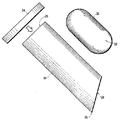
図1は、従来の技術による湿潤剤の供給システムを示す側面図である。湿潤剤12は、カートン10の中に収容される。カートンの底部20を取除くと湿潤剤を露出することができる。次いで、カートンを土壌16の穴22の中に差し込む。カートンの底を通じて土壌と接触する湿潤剤は、細菌による作用で液状化され、植物14の根系18に水を供給する。湿潤剤の露出部分が液状化されていくにつれ、含水ゲルの次の層が細菌に露出され、カートンの底から滴下していく。湿潤剤が完全に液状化したら、空になったカートンを土壌から引き抜く。
【0006】
この供給システムは幾つかの課題を有する。カートンは見た目が悪いので、観葉植物への使用に適していない。また、カートンを引き抜かなければ、カートン内の湿潤剤が完全に液状化したかどうかの判断ができない。さらに、湿潤剤を新たに補給したい場合、カートンをまず取除き、新しいカートンと取り替える必要がある。その際、取除かれたカートンによって形成された穴の中に土が崩れ落ちてしまう可能性がある。その場合、新しいカートンを穴に挿入するのに時間が掛かり、煩わしい。
【0007】
湿潤剤を収容する「コップ」(図示せず)によって、植物に所定量の水を与えるシステムもある。このコップを、開封後、逆さまの状態で土壌の表面に配置することでコップ内の湿潤剤が細菌の作用を受けるようにするものである。しかし、このコップも、見た目が良くない。さらに、コップは風、雨又は雹によって簡単に倒されてしまうため、屋外の使用に適していない。さらに、コップの下にできる、影のある湿った場所に昆虫の巣ができ易い。
【0008】
よって、植物に水分を供給するための方法及びシステムを提供することが望ましい。また、消耗された湿潤剤を簡単に交換できるシステムであるほうが好ましい。さらに、観葉植物や生け花に使用しても見苦しくない外観を有するシステムであれば非常に良い。
【0009】
発明の概要
本発明は、植えてある植物や植物を切って飾ったもの(生け花等)等の植物組織に、湿潤剤の水分を制御供給するためのシステム及び方法を提供する。本発明によると、斜角を有する供給チューブの差込側端部が、植物の根系付近の土壌の中に配置される。湿潤剤を封入したインサートの一端を開封して湿潤剤を露出させ、供給チューブの受側端部を介してその中空胴部に挿入する。次いで、受側端部にキャップを着脱可能に装着し、インサートを供給チューブの中空胴部内に閉じ込めることで、蒸発による水分の損失を抑制し、チューブ内に異物又は昆虫が紛れ込むことを防止する。インサートが完全に消耗されると、キャップを取外し、空のインサートを取除き、供給チューブの中空胴部に新しいインサートを挿入することで交換する。
【0010】
インサートは、好ましくは、薄いプラスチックの中に湿潤剤を封入したソーセージ形状のチャブ(chub)からなるものである。ただし、供給チューブは、様々な形状のインサートを受けるような構造にすることが可能である。また、湿潤剤を、例えばタンク又はキャニスタから直接供給チューブ内に注入することもできる。
【0011】
植物に供給される水の量と、水が供給される時間は、インサートの大きさと、土壌と接触する湿潤剤の表面積によって決まる。湿潤剤に少量の食品用防腐剤を添加することで、細菌の作用を抑制し、液状化の速度をさらに制御することができる。
【0012】
発明の詳細な説明
本発明は、湿潤剤から植物組織に、水を制御供給するためのシステム及び方法である。本発明によるチューブ型供給システムは、植えてある植物にも植物を切って飾ったもの(生け花等)にも、所定の量及び速度で水を与えるために使用することができる。本発明の好適な実施形態は、上記アヴェラによる米国特許第4865640に記載の湿潤剤を供給するのに最適である。しかし、本発明は、その他の湿潤剤の供給にも同様に適用することが可能である。
【0013】
図2は、本発明による供給チューブの側面図である。本発明の好適な実施形態によると、供給チューブ34は、例えばプラスチック、セラミック又はガラス等の非腐食性の材料からなる中空の剛直な管材である。ただし、供給チューブは、湿潤剤インサート30を支持できるほどの剛性を有するものであれば、その材料又は材料の組合せは問わない。この種の材料として、金属、木材、ゴム及び天然又は合成繊維等があるが、これらに限定される訳ではない。供給チューブは、ブロー成型、射出成型又は押出成型等の方法で作成することができる。
【0014】
供給チューブの差込側端28は、チューブを土壌に差込み易くするため、尖36に向かって斜角をなす。供給チューブの差込側端は、植物(図示せず)の根系付近の土壌中に配置される。本発明の好適な実施形態によると、供給チューブの僅か一部しか土壌から突き出ないよう、供給チューブを土壌の奥深くまで押し込む。しかし、他の実施形態では、供給チューブがどれだけ土壌からはみ出ていても構わず、これは供給チューブの全長、植物の根系の深さ及び供給すべく湿潤剤の量等、様々な要因によって任意に決めることができる。
【0015】
湿潤剤32を収容するインサート30は、その一端(図示せず)を開封し、湿潤剤を露出させ、受側端部26を介して供給チューブの中空胴部(図示せず)に設置する。供給チューブの斜角によって、土壌の細菌作用を受ける湿潤剤の表面積を大きくする。
【0016】
次いで、キャップ24を受側端部に着脱可能に装着し、インサートを供給チューブの中空胴部内に閉じ込める。消耗されたインサートは、キャップを取り外し、空のインサートを取り出し、供給チューブの中空胴部に新しいインサートを設置しておくことで簡単に交換することができる。挿入された湿潤剤を交換するために、供給チューブを土壌から引き抜く必要はない。
【0017】
本発明の好適な実施形態では、インサートは、湿潤剤を封入した細いプラスチックの管材からなる。この細い管材は、用途によって、様々な長さや直径にすることができる。湿潤材の液状化率は土壌と接触する湿潤剤の量によるので、植物に供給される水の量と水が供給される時間はインサートの大きさや直径によって決まる。
【0018】
供給チューブの中空胴部は、所定の長さ及び直系を有するインサートを受けるための構造を有する。好適な実施形態において、インサートはソーセージに似たチャブ(chub)の形状を有する。好適な実施形態の1つの実施例において、供給チューブは、長さが約7インチ、直径が約2インチであり、チャブはその中に収容できるような寸法を有する。インサートは、その他にも、紙、金属、金属箔及びゴム等を含むがそれらに限定されない、適切な材料又は材料の組合せからなるものであっても良い。
【0019】
本発明の他の実施形態によると、インサート及び供給チューブは、任意の形状及び寸法を有するものである。例えば、供給チューブの形状を、カートン状のインサートを受けることのできるようなものにする。こうすることにより、本発明を従来のカートンに使用できるようになる。供給チューブによって、カートンの外観を改善することができる。さらに、本発明によるチューブ型供給システムを使用することで、簡単にカートンを取り外し、その内容が完全に液状化したかどうかを確かめることが可能になる。そして、交換が必要であれば、新しいカートンを簡単に中空胴部に設置することができる。さらに、供給チューブを、従来技術による供給カップを受けるような構造にすることができる。
【0020】
本発明のさらなる実施形態では、供給チューブの中に湿潤材を直接注入する。例えば、タンクに貯蔵された湿潤材を手作業で又は自動的に供給チューブに補給することができる。この実施形態は、植林や農業等の野外の用途に適している。このような用途には、水を連続的に補給する必要がある。本発明による供給チューブを、植物を植える際又はその後に、土壌に配置することができる。続いて、貯蔵タンクから湿潤材を中空胴部に直接注入することで供給チューブに充填し、補充することができる。固定又は移動貯蔵タンクを設置することができない場所においては、湿潤剤を含むインサートを使用して植物に水を制御供給することができる。
【0021】
図3は、本発明によるチューブ型供給システム40の側断面図である。供給チューブ22は、差込側端部28が植物44の根系48付近の土壌46の中に配置される。この場合、湿潤剤32を封入したインサート30を、インサートの開封端42が土壌の細菌作用を受けるようにして供給チューブの中空胴部50の中に差し込む。次いで、キャップ24を受側端部26に装着し、インサートを供給チューブの中空胴部の中に閉じ込める。この好適な実施形態では、キャップが蒸発による水分の損失を防止し、チューブ内に異物や昆虫が紛れ込むことを防ぐ。
【0022】
図4は、本発明によるチューブ型供給システムにおけるインサートの差込み過程を示す側断面図である。図中、チャブ型インサートの一端42が、開封又は切断され、湿潤剤が露出される。次いで、インサート30を、切断された端部42を先にして、供給チューブ22の中空胴部50の中に挿入し、湿潤剤が土壌の細菌作用を受けるようにする。そして、キャップ(図示せず)を受側端部26に装着し、供給チューブの中空胴部にインサートを閉じ込める。
【0023】
本発明を好適な実施形態に従って説明したが、この説明は、発明の範囲を何等制限することを意図するものではない。本発明の趣旨及び範囲から逸脱せずに、ここで開示した発明の構成、動作及び詳細に対して当業者にとって明白な改良、変更及び変形を行うことが可能である。
【0024】
例えば、湿潤剤に少量の食品用防腐剤を添加することで湿潤剤の液状化速度をさらに制御することができる。この防腐剤によって細菌の活動を抑制し、完全液状化までの時間を延長することができる。好適な防腐剤として、安息香酸ナトリウムを、水の量に対する重量%として0.005%ないし0.05%添加することができる。
【0025】
観葉植物や生け花に使用する場合、その外観を改善するために、供給チューブ又はキャップに修飾や色を加えることも考えられる。また、供給チューブ又はキャップの形状を、例えば茎、切り株又は岩石等の自然界に存在する物体を模倣するような形状又は色にすることで、目立たなくすることもできる。例えば、本発明の好適な実施形態において、供給チューブ及びキャップは、土壌の色に溶け込むように、茶色くしてある。ただし、他の実施形態における供給チューブ及びキャップの色は任意である。
【0026】
さらに、供給チューブをキャップ無しで使用することも可能である。このようなキャップ無しチューブは、湿潤剤を直接充填したものであっても、湿潤剤を封入したインサートを受けるものであっても良い。
【図面の簡単な説明】
【図1】
図1は、従来の技術による湿潤剤の供給システムを示す側面図である。
【図2】
図2は、本発明による供給チューブを示す側面図である。
【図3】
図3は、本発明によるチューブ型供給システムを示す側断面図である。
【図4】
図4は、本発明によるチューブ型供給システムにおけるインサートの差込みを示す側断面図である。[0001]
BACKGROUND OF THE INVENTION TECHNICAL FIELD OF THE INVENTION The present invention relates to the provision of moist substrates to plant tissue. More specifically, the present invention relates to systems and methods for controlling and supplying water to plants.
[0002]
2. 2. Description of the Related Art The problem of maintaining the water content of soil so that growing plants can be maintained has long been recognized. The most common method of supplying water to soil is manual or irrigation by automatic means such as sprinkler or drip irrigation. However, manual irrigation requires a great deal of time and effort. Also, automatic irrigation systems are very expensive to install and operate.
[0003]
Wetting agents have been used to solve the problems of manual and automatic irrigation systems. The humectant releases moisture to its surroundings. Such wetting agents are described, for example, by Avera in U.S. Pat. No. 4,865,640, "Moisturizing Agent". Avella's wetting agents are gel analogs that have a dry feel and are half-shaped in appearance. The humectant, while being solid, can contain about 98% moisture therein.
[0004]
The water thus confined in the individual is gradually converted to liquid water when placed in natural soil where microorganisms are present. Bacteria and other microorganisms that liquefy the encapsulated water do not penetrate the interior of the gel but act on its surface. Therefore, the liquefaction rate of the wetting agent or the like by Avera can be adjusted by changing the surface area of the wetting agent that comes into contact with the soil.
[0005]
FIG. 1 is a side view showing a wetting agent supply system according to the related art. The
[0006]
This supply system has several problems. Cartons are not suitable for use on houseplants because they look bad. Unless the carton is pulled out, it cannot be determined whether the wetting agent in the carton has completely liquefied. Furthermore, if a new supply of humectant is desired, the carton must first be removed and replaced with a new carton. At that time, there is a possibility that the soil collapses into a hole formed by the removed carton. In that case, inserting a new carton into the hole takes time and is cumbersome.
[0007]
Some systems provide a predetermined amount of water to the plant by a "cup" (not shown) containing a humectant. After opening the cup, the cup is placed upside down on the surface of the soil so that the humectant in the cup is affected by bacteria. However, this cup also looks bad. In addition, cups are not suitable for outdoor use because they are easily knocked down by wind, rain or hail. In addition, insect nests are likely to form in moist, shaded areas that can form beneath the glass.
[0008]
Therefore, it is desirable to provide a method and system for supplying water to plants. In addition, it is preferable that the system be capable of easily replacing the consumed wetting agent. Furthermore, a system having an appearance that is not unsightly even when used for houseplants and flower arrangements is very good.
[0009]
SUMMARY OF THE INVENTION The present invention provides a system and method for controlling and supplying moisture from a humectant to plant tissue, such as a plant being planted or a plant cut and decorated (flower arrangement, etc.). According to the invention, the insertion end of the beveled feed tube is placed in the soil near the root system of the plant. One end of the insert enclosing the humectant is opened to expose the humectant, and inserted into the hollow body through the receiving end of the supply tube. Next, a cap is detachably attached to the receiving end, and the insert is confined in the hollow body of the supply tube, thereby suppressing loss of water due to evaporation and preventing foreign matter or insects from entering the tube. When the insert is completely depleted, remove the cap, remove the empty insert, and replace by inserting a new insert into the hollow body of the supply tube.
[0010]
The insert preferably consists of a sausage-shaped tub with a wetting agent encapsulated in a thin plastic. However, the supply tube can be configured to receive inserts of various shapes. Also, the wetting agent can be injected into the supply tube directly from, for example, a tank or canister.
[0011]
The amount of water supplied to the plant, and the time for which water is supplied, depends on the size of the insert and the surface area of the wetting agent in contact with the soil. By adding a small amount of food preservative to the wetting agent, the action of bacteria can be suppressed and the rate of liquefaction can be further controlled.
[0012]
DETAILED DESCRIPTION OF THE INVENTION The present invention is a system and method for the controlled supply of water from humectants to plant tissue. The tubular feed system according to the present invention can be used to provide water at a predetermined amount and rate, both to planted plants and to cut and decorated plants (flower arrangements, etc.). The preferred embodiment of the present invention is best suited for providing a humectant as described in the above mentioned U.S. Pat. No. 4,865,640. However, the invention is equally applicable to the supply of other wetting agents.
[0013]
FIG. 2 is a side view of a supply tube according to the present invention. According to a preferred embodiment of the present invention, the
[0014]
The
[0015]
The
[0016]
The
[0017]
In a preferred embodiment of the invention, the insert comprises a thin plastic tubing encapsulating a wetting agent. The thin tubing can be of various lengths and diameters depending on the application. Since the liquefaction rate of the wetting agent depends on the amount of wetting agent that comes into contact with the soil, the amount of water supplied to the plant and the time for which water is supplied are determined by the size and diameter of the insert.
[0018]
The hollow body of the supply tube has a structure for receiving an insert having a predetermined length and a straight line. In a preferred embodiment, the insert has the shape of a tub resembling sausage. In one example of the preferred embodiment, the supply tube is about 7 inches long and about 2 inches in diameter, and the tub is dimensioned to fit therein. The insert may alternatively be made of any suitable material or combination of materials, including but not limited to paper, metal, metal foil, rubber, and the like.
[0019]
According to another embodiment of the present invention, the insert and the supply tube have any shape and size. For example, the shape of the supply tube is such that it can receive a carton-shaped insert. This allows the invention to be used in conventional cartons. The supply tube can improve the appearance of the carton. Furthermore, the use of the tube-type feeding system according to the invention makes it possible to easily remove the carton and to check whether its contents have completely liquefied. And if replacement is necessary, a new carton can be easily installed in the hollow body. Further, the supply tube can be configured to receive a supply cup according to the prior art.
[0020]
In a further embodiment of the invention, the wetting material is injected directly into the supply tube. For example, wetting material stored in a tank can be replenished to the supply tube manually or automatically. This embodiment is suitable for outdoor applications such as tree planting and agriculture. Such applications require a continuous supply of water. The supply tube according to the invention can be placed in the soil during or after planting the plant. Subsequently, the supply tube can be filled and replenished by injecting the wetting material directly from the storage tank into the hollow body. In places where fixed or mobile storage tanks cannot be installed, inserts containing humectants can be used to provide a controlled supply of water to the plants.
[0021]
FIG. 3 is a side sectional view of a tube-type supply system 40 according to the present invention. The
[0022]
FIG. 4 is a side sectional view showing a process of inserting an insert in the tube type feeding system according to the present invention. In the figure, one end 42 of the tub-type insert is opened or cut, exposing the wetting agent. The
[0023]
Although the present invention has been described in accordance with a preferred embodiment, this description is not intended to limit the scope of the invention in any way. Without departing from the spirit and scope of the invention, modifications, changes and variations that are obvious to those skilled in the art can be made to the structure, operation and details of the invention disclosed herein.
[0024]
For example, the liquefaction rate of the wetting agent can be further controlled by adding a small amount of a food preservative to the wetting agent. This preservative can suppress the activity of bacteria and extend the time until complete liquefaction. As a preservative, sodium benzoate can be added in an amount of 0.005% to 0.05% by weight based on the amount of water.
[0025]
When used for houseplants and ikebana, it is conceivable to modify or color the supply tube or cap to improve its appearance. Also, the shape of the supply tube or cap can be made inconspicuous by shaping it in a shape or color that mimics naturally occurring objects such as stems, stumps or rocks. For example, in a preferred embodiment of the present invention, the supply tube and cap are browned to blend into the soil color. However, the colors of the supply tube and the cap in other embodiments are arbitrary.
[0026]
Further, it is possible to use the supply tube without the cap. Such uncapped tubes may be directly filled with a wetting agent or may receive an insert enclosing the wetting agent.
[Brief description of the drawings]
FIG.
FIG. 1 is a side view showing a wetting agent supply system according to the related art.
FIG. 2
FIG. 2 is a side view showing a supply tube according to the present invention.
FIG. 3
FIG. 3 is a side sectional view showing a tube type supply system according to the present invention.
FIG. 4
FIG. 4 is a side sectional view showing insertion of an insert in the tube type feeding system according to the present invention.
Claims (22)
供給チューブの受側端部を着脱可能に密閉するためのキャップを具備し、
該供給チューブが、差込側端部を植物の根系付近の土壌中に配置するための構造を有し、
該中空胴部が、受側端部から湿潤剤を受け、湿潤材が差込側端部の断面から土壌と接触することによって差込側端部から湿潤剤の水分を供給するための構造を有することを特徴とする植物組織に水を供給するための供給システム。A supply tube having a receiving end and an insertion end, a supply tube having a hollow body extending from the receiving end to the insertion end, and a detachably sealing the receiving end of the supply tube. Equipped with a cap of
The supply tube has a structure for placing the insertion-side end in soil near the root system of the plant,
The hollow body receives a humectant from the receiving end, and has a structure for supplying moisture of the humectant from the insertion end by contacting the humectant with the soil from the cross section of the insertion end. A supply system for supplying water to a plant tissue, comprising:
受側端部及び差込側端部を有し、さらに受側端部から差込側端部に亘る中空胴部を有するチューブ、及び
供給チューブの受側端部を着脱可能に密閉するためのキャップを具備し、
該供給チューブが、差込側端部が植物の根系付近の土壌中に配置するための構造を有し、
該中空胴部が、受側端部から湿潤剤を受け、湿潤材が差込側端部の断面から土壌と接触することによって差込側端部から湿潤剤の水分を供給するための構造を有することを特徴とする植物組織に水を供給するための供給チューブ。A supply tube in a supply system for supplying water to plant tissue,
A tube having a receiving end and a plug-in end, and further having a hollow body extending from the receiving end to the plug-in end, and a detachably sealing the receiving end of the supply tube. Equipped with a cap,
The supply tube has a structure for placing the insertion-side end in soil near the root system of the plant,
The hollow body receives a humectant from the receiving end, and has a structure for supplying moisture of the humectant from the insertion end by contacting the humectant with the soil from the cross section of the insertion end. A supply tube for supplying water to plant tissue, characterized in that the supply tube has water.
湿潤材を、該供給チューブの差込側端部の断面から土壌と接触するように、供給チューブの中空胴部の中に挿入し、
キャップによって供給チューブの受側端部を着脱可能に密閉する過程を有する、植物組織に水を供給するための方法。Placing the insertion end of the supply tube having a hollow body extending from the receiving end to the insertion end in the soil near the root system of the plant,
Wetting material is inserted into the hollow body of the supply tube so that it comes into contact with the soil from the cross section of the insertion end of the supply tube,
A method for supplying water to plant tissue, comprising a step of removably sealing a receiving end of a supply tube with a cap.
供給チューブの中空胴部の中に湿潤剤を追加注入し、
供給チューブの受側端部にキャップを戻す過程をさらに有する請求項14に記載の方法。Remove the cap from the receiving end of the supply tube,
Inject additional wetting agent into the hollow body of the supply tube,
15. The method of claim 14, further comprising returning the cap to the receiving end of the supply tube.
インサートに湿潤剤を封入し、
インサートの一端を開封することで湿潤剤を露出させ、
開封側に露出された湿潤剤が、供給チューブの差込側端部から土壌と接触するように、インサートを供給チューブの受側端部から中空胴部の中に設置する過程をさらに有する請求項14に記載の方法。The process of inserting the wetting agent,
Insert a wetting agent into the insert,
Expose the wetting agent by opening one end of the insert,
The method according to claim 1, further comprising: installing the insert into the hollow body from the receiving end of the supply tube so that the wetting agent exposed on the opening side comes into contact with the soil from the insertion end of the supply tube. 15. The method according to 14.
供給チューブの中空胴部内に収容された空のインサートを取り出し、
供給チューブの中空胴部内に新しいインサートを設置し、
供給チューブの受側端部にキャップを戻す過程をさらに有する請求項16に記載の方法。Remove the cap from the receiving end of the supply tube,
Take out the empty insert contained in the hollow body of the supply tube,
Install a new insert in the hollow body of the supply tube,
17. The method of claim 16, further comprising returning the cap to the receiving end of the supply tube.
該中空胴部内に設けた湿潤剤を具備し、
該供給チューブが、差込側端部を植物の根系付近の土壌中に配置するための構造を有し、
該供給チューブが、受側端部から湿潤剤を受け、差込側端部から湿潤剤の水分を供給するための構造を有することを特徴とする植物組織に水を供給するための供給システム。A supply tube having a receiving end and an insertion end, and further having a hollow body extending from the receiving end to the insertion end, and a wetting agent provided in the hollow body,
The supply tube has a structure for placing the insertion-side end in soil near the root system of the plant,
A supply system for supplying water to plant tissue, wherein the supply tube has a structure for receiving a humectant from a receiving end and supplying moisture of the humectant from an insertion end.
Applications Claiming Priority (1)
| Application Number | Priority Date | Filing Date | Title |
|---|---|---|---|
| PCT/US2000/041176 WO2002058458A1 (en) | 2000-10-16 | 2000-10-16 | Tube delivery system and method |
Publications (2)
| Publication Number | Publication Date |
|---|---|
| JP2004517632A true JP2004517632A (en) | 2004-06-17 |
| JP2004517632A5 JP2004517632A5 (en) | 2007-12-06 |
Family
ID=21742148
Family Applications (1)
| Application Number | Title | Priority Date | Filing Date |
|---|---|---|---|
| JP2002558801A Pending JP2004517632A (en) | 2000-10-16 | 2000-10-16 | Tube supply system and method |
Country Status (11)
| Country | Link |
|---|---|
| EP (1) | EP1341408A1 (en) |
| JP (1) | JP2004517632A (en) |
| KR (1) | KR20020071889A (en) |
| AU (1) | AU2001219650B2 (en) |
| BR (1) | BR0016917A (en) |
| EE (1) | EE200200327A (en) |
| IL (2) | IL150218A0 (en) |
| MX (1) | MXPA03003330A (en) |
| NO (1) | NO20022872D0 (en) |
| TW (1) | TW548074B (en) |
| WO (1) | WO2002058458A1 (en) |
Families Citing this family (3)
| Publication number | Priority date | Publication date | Assignee | Title |
|---|---|---|---|---|
| CN102972127B (en) * | 2012-12-25 | 2015-03-11 | 北京林业大学 | Punching device for cuttage forestation on sand |
| CN105284261A (en) * | 2015-11-13 | 2016-02-03 | 叶富梅 | Fertilizing method for street trees |
| CN107926663B (en) * | 2017-12-27 | 2023-04-11 | 南京工程学院 | Charging type sand fixation water economizer |
Citations (7)
| Publication number | Priority date | Publication date | Assignee | Title |
|---|---|---|---|---|
| US4051628A (en) * | 1975-11-12 | 1977-10-04 | Hortigro, Inc. | Apparatus for the improved dispensing of plant nutriments |
| JPS5855460U (en) * | 1981-10-09 | 1983-04-15 | 三洋化成工業株式会社 | Plant drying prevention stake |
| US4453343A (en) * | 1983-04-08 | 1984-06-12 | Grimes Sr Roland S | Irrigation systems |
| JPS61197855U (en) * | 1985-05-30 | 1986-12-10 | ||
| JPS6257662U (en) * | 1985-09-28 | 1987-04-09 | ||
| JPS6344817U (en) * | 1986-09-10 | 1988-03-25 | ||
| US4865640A (en) * | 1986-09-23 | 1989-09-12 | Avera Fitzhugh Lee | Moisturizing agent |
Family Cites Families (6)
| Publication number | Priority date | Publication date | Assignee | Title |
|---|---|---|---|---|
| US2791347A (en) * | 1954-11-01 | 1957-05-07 | Boehm Donald | Underground receptacles |
| US2931140A (en) * | 1958-05-13 | 1960-04-05 | Rombough | Cartridges for fertilizers, fungicides and/or insecticides |
| US3337326A (en) * | 1964-12-28 | 1967-08-22 | Harry M May | Process for preparing a soil conditioning and erosion preventing composition from sugar cane bagasse |
| US4089133A (en) * | 1976-12-08 | 1978-05-16 | Duncan Vinal S | Device for liquid feeding of potted plants and the like |
| US4745706A (en) * | 1986-10-14 | 1988-05-24 | Robert Muza | Plant watering and feeding stake |
| US5924240A (en) * | 1996-08-14 | 1999-07-20 | Harrison; Mark R. | Device to water and fertilize plants |
-
2000
- 2000-10-16 MX MXPA03003330A patent/MXPA03003330A/en not_active Application Discontinuation
- 2000-10-16 EP EP00982646A patent/EP1341408A1/en not_active Withdrawn
- 2000-10-16 AU AU2001219650A patent/AU2001219650B2/en not_active Ceased
- 2000-10-16 BR BR0016917-0A patent/BR0016917A/en active Search and Examination
- 2000-10-16 EE EEP200200327A patent/EE200200327A/en unknown
- 2000-10-16 WO PCT/US2000/041176 patent/WO2002058458A1/en active Application Filing
- 2000-10-16 IL IL15021800A patent/IL150218A0/en active IP Right Grant
- 2000-10-16 KR KR1020027007755A patent/KR20020071889A/en not_active Application Discontinuation
- 2000-10-16 JP JP2002558801A patent/JP2004517632A/en active Pending
-
2001
- 2001-07-13 TW TW090117210A patent/TW548074B/en not_active IP Right Cessation
-
2002
- 2002-06-13 IL IL150218A patent/IL150218A/en not_active IP Right Cessation
- 2002-06-14 NO NO20022872A patent/NO20022872D0/en not_active Application Discontinuation
Patent Citations (7)
| Publication number | Priority date | Publication date | Assignee | Title |
|---|---|---|---|---|
| US4051628A (en) * | 1975-11-12 | 1977-10-04 | Hortigro, Inc. | Apparatus for the improved dispensing of plant nutriments |
| JPS5855460U (en) * | 1981-10-09 | 1983-04-15 | 三洋化成工業株式会社 | Plant drying prevention stake |
| US4453343A (en) * | 1983-04-08 | 1984-06-12 | Grimes Sr Roland S | Irrigation systems |
| JPS61197855U (en) * | 1985-05-30 | 1986-12-10 | ||
| JPS6257662U (en) * | 1985-09-28 | 1987-04-09 | ||
| JPS6344817U (en) * | 1986-09-10 | 1988-03-25 | ||
| US4865640A (en) * | 1986-09-23 | 1989-09-12 | Avera Fitzhugh Lee | Moisturizing agent |
Also Published As
| Publication number | Publication date |
|---|---|
| AU2001219650B2 (en) | 2006-11-30 |
| WO2002058458A8 (en) | 2003-03-27 |
| BR0016917A (en) | 2002-10-15 |
| NO20022872D0 (en) | 2002-06-14 |
| EE200200327A (en) | 2003-12-15 |
| MXPA03003330A (en) | 2004-12-03 |
| KR20020071889A (en) | 2002-09-13 |
| IL150218A0 (en) | 2002-12-01 |
| EP1341408A1 (en) | 2003-09-10 |
| TW548074B (en) | 2003-08-21 |
| WO2002058458A1 (en) | 2002-08-01 |
| IL150218A (en) | 2006-09-05 |
Similar Documents
| Publication | Publication Date | Title |
|---|---|---|
| US3271900A (en) | Automatic pure cultivator | |
| US5836106A (en) | Plant watering control device | |
| US6138408A (en) | Tube delivery system and method | |
| JPH05192046A (en) | Plant culture apparatus | |
| JP2002218846A (en) | Water level-controlling device of water vessel type flower pot | |
| US5016389A (en) | Method and apparatus for supply of water and nutrients to plants | |
| CN201754693U (en) | Convenient flower growing device | |
| US5400545A (en) | Method for controlling the delivery of liquids to a plant | |
| KR101085417B1 (en) | Automatic water supplying flowerpot for planting moss | |
| US6957512B2 (en) | Method for the propogation of and aeroponic growing of plants and vessels therefor | |
| JP2004517632A (en) | Tube supply system and method | |
| US20080163547A1 (en) | Apparatus for irrigation and drainage in a plant vase | |
| GB2267205A (en) | Apparatus for watering plants | |
| AU2001219650A1 (en) | Tube delivery system and method | |
| US20060086045A1 (en) | Gelatinous moisturizing agent delivery system and method | |
| JP4003103B2 (en) | Automatic watering plant cultivation container | |
| JP2006174829A (en) | Simplified hydroponics container | |
| JP3262724B2 (en) | Cultivation equipment | |
| CN2224508Y (en) | Automatic watering flower-pot | |
| JP2857605B2 (en) | Flower vase | |
| US4256046A (en) | Plant cultivation devices and methods | |
| CN2414614Y (en) | Wall hole nested pot | |
| JPH05219845A (en) | Culturing apparatus and tool used therefor | |
| WO2007130013A1 (en) | Gelatinous moisturizing agent delivery system and method | |
| JP2001320970A (en) | Hydroponic method using pet bottle |
Legal Events
| Date | Code | Title | Description |
|---|---|---|---|
| A521 | Request for written amendment filed |
Free format text: JAPANESE INTERMEDIATE CODE: A523 Effective date: 20071005 |
|
| A621 | Written request for application examination |
Free format text: JAPANESE INTERMEDIATE CODE: A621 Effective date: 20071005 |
|
| A131 | Notification of reasons for refusal |
Free format text: JAPANESE INTERMEDIATE CODE: A131 Effective date: 20100209 |
|
| A601 | Written request for extension of time |
Free format text: JAPANESE INTERMEDIATE CODE: A601 Effective date: 20100510 |
|
| A602 | Written permission of extension of time |
Free format text: JAPANESE INTERMEDIATE CODE: A602 Effective date: 20100519 |
|
| A601 | Written request for extension of time |
Free format text: JAPANESE INTERMEDIATE CODE: A601 Effective date: 20100609 |
|
| A602 | Written permission of extension of time |
Free format text: JAPANESE INTERMEDIATE CODE: A602 Effective date: 20100616 |
|
| A601 | Written request for extension of time |
Free format text: JAPANESE INTERMEDIATE CODE: A601 Effective date: 20100708 |
|
| A602 | Written permission of extension of time |
Free format text: JAPANESE INTERMEDIATE CODE: A602 Effective date: 20100715 |
|
| A02 | Decision of refusal |
Free format text: JAPANESE INTERMEDIATE CODE: A02 Effective date: 20101102 |