JP2004505812A - Adapter for welding objects to plastic - Google Patents
Adapter for welding objects to plastic Download PDFInfo
- Publication number
- JP2004505812A JP2004505812A JP2002519164A JP2002519164A JP2004505812A JP 2004505812 A JP2004505812 A JP 2004505812A JP 2002519164 A JP2002519164 A JP 2002519164A JP 2002519164 A JP2002519164 A JP 2002519164A JP 2004505812 A JP2004505812 A JP 2004505812A
- Authority
- JP
- Japan
- Prior art keywords
- adapter
- plastic
- foot
- feet
- weld
- Prior art date
- Legal status (The legal status is an assumption and is not a legal conclusion. Google has not performed a legal analysis and makes no representation as to the accuracy of the status listed.)
- Abandoned
Links
- 229920003023 plastic Polymers 0.000 title claims abstract description 145
- 239000004033 plastic Substances 0.000 title claims abstract description 145
- 238000003466 welding Methods 0.000 title claims description 12
- 230000008878 coupling Effects 0.000 claims abstract description 30
- 238000010168 coupling process Methods 0.000 claims abstract description 30
- 238000005859 coupling reaction Methods 0.000 claims abstract description 30
- 230000007246 mechanism Effects 0.000 claims abstract description 30
- 239000002828 fuel tank Substances 0.000 claims description 40
- 239000000446 fuel Substances 0.000 claims description 37
- 238000000034 method Methods 0.000 claims description 22
- 239000000463 material Substances 0.000 claims description 15
- 239000000088 plastic resin Substances 0.000 claims description 8
- 238000001816 cooling Methods 0.000 claims description 6
- 238000000465 moulding Methods 0.000 claims description 5
- 238000010438 heat treatment Methods 0.000 claims description 4
- 230000035515 penetration Effects 0.000 claims description 3
- 230000004044 response Effects 0.000 claims description 2
- 230000007423 decrease Effects 0.000 claims 1
- 238000002844 melting Methods 0.000 claims 1
- 230000008018 melting Effects 0.000 claims 1
- 238000010586 diagram Methods 0.000 abstract description 2
- 239000010410 layer Substances 0.000 description 18
- 229930195733 hydrocarbon Natural products 0.000 description 10
- 150000002430 hydrocarbons Chemical class 0.000 description 10
- 239000004215 Carbon black (E152) Substances 0.000 description 9
- 230000004888 barrier function Effects 0.000 description 8
- 230000006378 damage Effects 0.000 description 8
- 238000004519 manufacturing process Methods 0.000 description 8
- 230000008569 process Effects 0.000 description 7
- 229920001903 high density polyethylene Polymers 0.000 description 5
- 239000004700 high-density polyethylene Substances 0.000 description 5
- 230000015572 biosynthetic process Effects 0.000 description 4
- 239000007787 solid Substances 0.000 description 4
- 238000005452 bending Methods 0.000 description 3
- 238000000071 blow moulding Methods 0.000 description 3
- 230000008602 contraction Effects 0.000 description 3
- 238000002347 injection Methods 0.000 description 3
- 239000007924 injection Substances 0.000 description 3
- 238000003856 thermoforming Methods 0.000 description 3
- 229920001169 thermoplastic Polymers 0.000 description 3
- 239000004416 thermosoftening plastic Substances 0.000 description 3
- 239000002131 composite material Substances 0.000 description 2
- 239000004715 ethylene vinyl alcohol Substances 0.000 description 2
- 239000007788 liquid Substances 0.000 description 2
- 229920000642 polymer Polymers 0.000 description 2
- 239000002356 single layer Substances 0.000 description 2
- 238000012876 topography Methods 0.000 description 2
- 229920000219 Ethylene vinyl alcohol Polymers 0.000 description 1
- 239000004677 Nylon Substances 0.000 description 1
- 229910000831 Steel Inorganic materials 0.000 description 1
- 238000010521 absorption reaction Methods 0.000 description 1
- 239000000853 adhesive Substances 0.000 description 1
- 230000001070 adhesive effect Effects 0.000 description 1
- XAGFODPZIPBFFR-UHFFFAOYSA-N aluminium Chemical compound [Al] XAGFODPZIPBFFR-UHFFFAOYSA-N 0.000 description 1
- 229910052782 aluminium Inorganic materials 0.000 description 1
- 239000006229 carbon black Substances 0.000 description 1
- 150000001875 compounds Chemical class 0.000 description 1
- 230000006835 compression Effects 0.000 description 1
- 238000007906 compression Methods 0.000 description 1
- 230000001627 detrimental effect Effects 0.000 description 1
- RZXDTJIXPSCHCI-UHFFFAOYSA-N hexa-1,5-diene-2,5-diol Chemical compound OC(=C)CCC(O)=C RZXDTJIXPSCHCI-UHFFFAOYSA-N 0.000 description 1
- 238000009434 installation Methods 0.000 description 1
- 238000005304 joining Methods 0.000 description 1
- 238000012986 modification Methods 0.000 description 1
- 230000004048 modification Effects 0.000 description 1
- 229920001778 nylon Polymers 0.000 description 1
- 238000005096 rolling process Methods 0.000 description 1
- 239000010959 steel Substances 0.000 description 1
- 239000012815 thermoplastic material Substances 0.000 description 1
- 230000001052 transient effect Effects 0.000 description 1
- 235000012773 waffles Nutrition 0.000 description 1
- XLYOFNOQVPJJNP-UHFFFAOYSA-N water Substances O XLYOFNOQVPJJNP-UHFFFAOYSA-N 0.000 description 1
Images
Classifications
-
- B—PERFORMING OPERATIONS; TRANSPORTING
- B29—WORKING OF PLASTICS; WORKING OF SUBSTANCES IN A PLASTIC STATE IN GENERAL
- B29B—PREPARATION OR PRETREATMENT OF THE MATERIAL TO BE SHAPED; MAKING GRANULES OR PREFORMS; RECOVERY OF PLASTICS OR OTHER CONSTITUENTS OF WASTE MATERIAL CONTAINING PLASTICS
- B29B13/00—Conditioning or physical treatment of the material to be shaped
- B29B13/02—Conditioning or physical treatment of the material to be shaped by heating
- B29B13/023—Half-products, e.g. films, plates
-
- B—PERFORMING OPERATIONS; TRANSPORTING
- B29—WORKING OF PLASTICS; WORKING OF SUBSTANCES IN A PLASTIC STATE IN GENERAL
- B29C—SHAPING OR JOINING OF PLASTICS; SHAPING OF MATERIAL IN A PLASTIC STATE, NOT OTHERWISE PROVIDED FOR; AFTER-TREATMENT OF THE SHAPED PRODUCTS, e.g. REPAIRING
- B29C51/00—Shaping by thermoforming, i.e. shaping sheets or sheet like preforms after heating, e.g. shaping sheets in matched moulds or by deep-drawing; Apparatus therefor
- B29C51/26—Component parts, details or accessories; Auxiliary operations
- B29C51/266—Auxiliary operations after the thermoforming operation
- B29C51/267—Two sheets being thermoformed in separate mould parts and joined together while still in the mould
-
- B—PERFORMING OPERATIONS; TRANSPORTING
- B29—WORKING OF PLASTICS; WORKING OF SUBSTANCES IN A PLASTIC STATE IN GENERAL
- B29C—SHAPING OR JOINING OF PLASTICS; SHAPING OF MATERIAL IN A PLASTIC STATE, NOT OTHERWISE PROVIDED FOR; AFTER-TREATMENT OF THE SHAPED PRODUCTS, e.g. REPAIRING
- B29C51/00—Shaping by thermoforming, i.e. shaping sheets or sheet like preforms after heating, e.g. shaping sheets in matched moulds or by deep-drawing; Apparatus therefor
- B29C51/26—Component parts, details or accessories; Auxiliary operations
- B29C51/42—Heating or cooling
- B29C51/421—Heating or cooling of preforms, specially adapted for thermoforming
-
- B—PERFORMING OPERATIONS; TRANSPORTING
- B29—WORKING OF PLASTICS; WORKING OF SUBSTANCES IN A PLASTIC STATE IN GENERAL
- B29C—SHAPING OR JOINING OF PLASTICS; SHAPING OF MATERIAL IN A PLASTIC STATE, NOT OTHERWISE PROVIDED FOR; AFTER-TREATMENT OF THE SHAPED PRODUCTS, e.g. REPAIRING
- B29C65/00—Joining or sealing of preformed parts, e.g. welding of plastics materials; Apparatus therefor
- B29C65/02—Joining or sealing of preformed parts, e.g. welding of plastics materials; Apparatus therefor by heating, with or without pressure
- B29C65/022—Particular heating or welding methods not otherwise provided for
- B29C65/028—Particular heating or welding methods not otherwise provided for making use of inherent heat, i.e. the heat for the joining comes from the moulding process of one of the parts to be joined
-
- B—PERFORMING OPERATIONS; TRANSPORTING
- B29—WORKING OF PLASTICS; WORKING OF SUBSTANCES IN A PLASTIC STATE IN GENERAL
- B29C—SHAPING OR JOINING OF PLASTICS; SHAPING OF MATERIAL IN A PLASTIC STATE, NOT OTHERWISE PROVIDED FOR; AFTER-TREATMENT OF THE SHAPED PRODUCTS, e.g. REPAIRING
- B29C66/00—General aspects of processes or apparatus for joining preformed parts
- B29C66/01—General aspects dealing with the joint area or with the area to be joined
- B29C66/05—Particular design of joint configurations
- B29C66/10—Particular design of joint configurations particular design of the joint cross-sections
- B29C66/13—Single flanged joints; Fin-type joints; Single hem joints; Edge joints; Interpenetrating fingered joints; Other specific particular designs of joint cross-sections not provided for in groups B29C66/11 - B29C66/12
- B29C66/131—Single flanged joints, i.e. one of the parts to be joined being rigid and flanged in the joint area
- B29C66/1312—Single flange to flange joints, the parts to be joined being rigid
-
- B—PERFORMING OPERATIONS; TRANSPORTING
- B29—WORKING OF PLASTICS; WORKING OF SUBSTANCES IN A PLASTIC STATE IN GENERAL
- B29C—SHAPING OR JOINING OF PLASTICS; SHAPING OF MATERIAL IN A PLASTIC STATE, NOT OTHERWISE PROVIDED FOR; AFTER-TREATMENT OF THE SHAPED PRODUCTS, e.g. REPAIRING
- B29C66/00—General aspects of processes or apparatus for joining preformed parts
- B29C66/50—General aspects of joining tubular articles; General aspects of joining long products, i.e. bars or profiled elements; General aspects of joining single elements to tubular articles, hollow articles or bars; General aspects of joining several hollow-preforms to form hollow or tubular articles
- B29C66/51—Joining tubular articles, profiled elements or bars; Joining single elements to tubular articles, hollow articles or bars; Joining several hollow-preforms to form hollow or tubular articles
- B29C66/53—Joining single elements to tubular articles, hollow articles or bars
- B29C66/532—Joining single elements to the wall of tubular articles, hollow articles or bars
- B29C66/5324—Joining single elements to the wall of tubular articles, hollow articles or bars said single elements being substantially annular, i.e. of finite length
- B29C66/53245—Joining single elements to the wall of tubular articles, hollow articles or bars said single elements being substantially annular, i.e. of finite length said articles being hollow
-
- B—PERFORMING OPERATIONS; TRANSPORTING
- B29—WORKING OF PLASTICS; WORKING OF SUBSTANCES IN A PLASTIC STATE IN GENERAL
- B29C—SHAPING OR JOINING OF PLASTICS; SHAPING OF MATERIAL IN A PLASTIC STATE, NOT OTHERWISE PROVIDED FOR; AFTER-TREATMENT OF THE SHAPED PRODUCTS, e.g. REPAIRING
- B29C66/00—General aspects of processes or apparatus for joining preformed parts
- B29C66/50—General aspects of joining tubular articles; General aspects of joining long products, i.e. bars or profiled elements; General aspects of joining single elements to tubular articles, hollow articles or bars; General aspects of joining several hollow-preforms to form hollow or tubular articles
- B29C66/61—Joining from or joining on the inside
-
- B—PERFORMING OPERATIONS; TRANSPORTING
- B29—WORKING OF PLASTICS; WORKING OF SUBSTANCES IN A PLASTIC STATE IN GENERAL
- B29C—SHAPING OR JOINING OF PLASTICS; SHAPING OF MATERIAL IN A PLASTIC STATE, NOT OTHERWISE PROVIDED FOR; AFTER-TREATMENT OF THE SHAPED PRODUCTS, e.g. REPAIRING
- B29C66/00—General aspects of processes or apparatus for joining preformed parts
- B29C66/70—General aspects of processes or apparatus for joining preformed parts characterised by the composition, physical properties or the structure of the material of the parts to be joined; Joining with non-plastics material
- B29C66/72—General aspects of processes or apparatus for joining preformed parts characterised by the composition, physical properties or the structure of the material of the parts to be joined; Joining with non-plastics material characterised by the structure of the material of the parts to be joined
- B29C66/723—General aspects of processes or apparatus for joining preformed parts characterised by the composition, physical properties or the structure of the material of the parts to be joined; Joining with non-plastics material characterised by the structure of the material of the parts to be joined being multi-layered
- B29C66/7234—General aspects of processes or apparatus for joining preformed parts characterised by the composition, physical properties or the structure of the material of the parts to be joined; Joining with non-plastics material characterised by the structure of the material of the parts to be joined being multi-layered comprising a barrier layer
-
- B—PERFORMING OPERATIONS; TRANSPORTING
- B60—VEHICLES IN GENERAL
- B60K—ARRANGEMENT OR MOUNTING OF PROPULSION UNITS OR OF TRANSMISSIONS IN VEHICLES; ARRANGEMENT OR MOUNTING OF PLURAL DIVERSE PRIME-MOVERS IN VEHICLES; AUXILIARY DRIVES FOR VEHICLES; INSTRUMENTATION OR DASHBOARDS FOR VEHICLES; ARRANGEMENTS IN CONNECTION WITH COOLING, AIR INTAKE, GAS EXHAUST OR FUEL SUPPLY OF PROPULSION UNITS IN VEHICLES
- B60K15/00—Arrangement in connection with fuel supply of combustion engines or other fuel consuming energy converters, e.g. fuel cells; Mounting or construction of fuel tanks
- B60K15/03—Fuel tanks
- B60K15/03177—Fuel tanks made of non-metallic material, e.g. plastics, or of a combination of non-metallic and metallic material
-
- F—MECHANICAL ENGINEERING; LIGHTING; HEATING; WEAPONS; BLASTING
- F16—ENGINEERING ELEMENTS AND UNITS; GENERAL MEASURES FOR PRODUCING AND MAINTAINING EFFECTIVE FUNCTIONING OF MACHINES OR INSTALLATIONS; THERMAL INSULATION IN GENERAL
- F16B—DEVICES FOR FASTENING OR SECURING CONSTRUCTIONAL ELEMENTS OR MACHINE PARTS TOGETHER, e.g. NAILS, BOLTS, CIRCLIPS, CLAMPS, CLIPS OR WEDGES; JOINTS OR JOINTING
- F16B9/00—Connections of rods or tubular parts to flat surfaces at an angle
- F16B9/05—Connections of rods or tubular parts to flat surfaces at an angle by way of an intermediate member
- F16B9/052—Connections of rods or tubular parts to flat surfaces at an angle by way of an intermediate member the intermediate member having a radial flange secured to the flat surface
-
- B—PERFORMING OPERATIONS; TRANSPORTING
- B29—WORKING OF PLASTICS; WORKING OF SUBSTANCES IN A PLASTIC STATE IN GENERAL
- B29C—SHAPING OR JOINING OF PLASTICS; SHAPING OF MATERIAL IN A PLASTIC STATE, NOT OTHERWISE PROVIDED FOR; AFTER-TREATMENT OF THE SHAPED PRODUCTS, e.g. REPAIRING
- B29C35/00—Heating, cooling or curing, e.g. crosslinking or vulcanising; Apparatus therefor
- B29C35/02—Heating or curing, e.g. crosslinking or vulcanizing during moulding, e.g. in a mould
- B29C35/08—Heating or curing, e.g. crosslinking or vulcanizing during moulding, e.g. in a mould by wave energy or particle radiation
- B29C35/0805—Heating or curing, e.g. crosslinking or vulcanizing during moulding, e.g. in a mould by wave energy or particle radiation using electromagnetic radiation
- B29C2035/0822—Heating or curing, e.g. crosslinking or vulcanizing during moulding, e.g. in a mould by wave energy or particle radiation using electromagnetic radiation using IR radiation
-
- B—PERFORMING OPERATIONS; TRANSPORTING
- B29—WORKING OF PLASTICS; WORKING OF SUBSTANCES IN A PLASTIC STATE IN GENERAL
- B29C—SHAPING OR JOINING OF PLASTICS; SHAPING OF MATERIAL IN A PLASTIC STATE, NOT OTHERWISE PROVIDED FOR; AFTER-TREATMENT OF THE SHAPED PRODUCTS, e.g. REPAIRING
- B29C49/00—Blow-moulding, i.e. blowing a preform or parison to a desired shape within a mould; Apparatus therefor
- B29C49/20—Blow-moulding, i.e. blowing a preform or parison to a desired shape within a mould; Apparatus therefor of articles having inserts or reinforcements ; Handling of inserts or reinforcements
- B29C2049/2017—Blow-moulding, i.e. blowing a preform or parison to a desired shape within a mould; Apparatus therefor of articles having inserts or reinforcements ; Handling of inserts or reinforcements outside the article
-
- B—PERFORMING OPERATIONS; TRANSPORTING
- B29—WORKING OF PLASTICS; WORKING OF SUBSTANCES IN A PLASTIC STATE IN GENERAL
- B29C—SHAPING OR JOINING OF PLASTICS; SHAPING OF MATERIAL IN A PLASTIC STATE, NOT OTHERWISE PROVIDED FOR; AFTER-TREATMENT OF THE SHAPED PRODUCTS, e.g. REPAIRING
- B29C49/00—Blow-moulding, i.e. blowing a preform or parison to a desired shape within a mould; Apparatus therefor
- B29C49/20—Blow-moulding, i.e. blowing a preform or parison to a desired shape within a mould; Apparatus therefor of articles having inserts or reinforcements ; Handling of inserts or reinforcements
-
- B—PERFORMING OPERATIONS; TRANSPORTING
- B29—WORKING OF PLASTICS; WORKING OF SUBSTANCES IN A PLASTIC STATE IN GENERAL
- B29C—SHAPING OR JOINING OF PLASTICS; SHAPING OF MATERIAL IN A PLASTIC STATE, NOT OTHERWISE PROVIDED FOR; AFTER-TREATMENT OF THE SHAPED PRODUCTS, e.g. REPAIRING
- B29C49/00—Blow-moulding, i.e. blowing a preform or parison to a desired shape within a mould; Apparatus therefor
- B29C49/22—Blow-moulding, i.e. blowing a preform or parison to a desired shape within a mould; Apparatus therefor using multilayered preforms or parisons
-
- B—PERFORMING OPERATIONS; TRANSPORTING
- B29—WORKING OF PLASTICS; WORKING OF SUBSTANCES IN A PLASTIC STATE IN GENERAL
- B29C—SHAPING OR JOINING OF PLASTICS; SHAPING OF MATERIAL IN A PLASTIC STATE, NOT OTHERWISE PROVIDED FOR; AFTER-TREATMENT OF THE SHAPED PRODUCTS, e.g. REPAIRING
- B29C51/00—Shaping by thermoforming, i.e. shaping sheets or sheet like preforms after heating, e.g. shaping sheets in matched moulds or by deep-drawing; Apparatus therefor
- B29C51/12—Shaping by thermoforming, i.e. shaping sheets or sheet like preforms after heating, e.g. shaping sheets in matched moulds or by deep-drawing; Apparatus therefor of articles having inserts or reinforcements
-
- B—PERFORMING OPERATIONS; TRANSPORTING
- B29—WORKING OF PLASTICS; WORKING OF SUBSTANCES IN A PLASTIC STATE IN GENERAL
- B29C—SHAPING OR JOINING OF PLASTICS; SHAPING OF MATERIAL IN A PLASTIC STATE, NOT OTHERWISE PROVIDED FOR; AFTER-TREATMENT OF THE SHAPED PRODUCTS, e.g. REPAIRING
- B29C51/00—Shaping by thermoforming, i.e. shaping sheets or sheet like preforms after heating, e.g. shaping sheets in matched moulds or by deep-drawing; Apparatus therefor
- B29C51/14—Shaping by thermoforming, i.e. shaping sheets or sheet like preforms after heating, e.g. shaping sheets in matched moulds or by deep-drawing; Apparatus therefor using multilayered preforms or sheets
-
- B—PERFORMING OPERATIONS; TRANSPORTING
- B29—WORKING OF PLASTICS; WORKING OF SUBSTANCES IN A PLASTIC STATE IN GENERAL
- B29C—SHAPING OR JOINING OF PLASTICS; SHAPING OF MATERIAL IN A PLASTIC STATE, NOT OTHERWISE PROVIDED FOR; AFTER-TREATMENT OF THE SHAPED PRODUCTS, e.g. REPAIRING
- B29C66/00—General aspects of processes or apparatus for joining preformed parts
- B29C66/70—General aspects of processes or apparatus for joining preformed parts characterised by the composition, physical properties or the structure of the material of the parts to be joined; Joining with non-plastics material
- B29C66/71—General aspects of processes or apparatus for joining preformed parts characterised by the composition, physical properties or the structure of the material of the parts to be joined; Joining with non-plastics material characterised by the composition of the plastics material of the parts to be joined
-
- B—PERFORMING OPERATIONS; TRANSPORTING
- B29—WORKING OF PLASTICS; WORKING OF SUBSTANCES IN A PLASTIC STATE IN GENERAL
- B29K—INDEXING SCHEME ASSOCIATED WITH SUBCLASSES B29B, B29C OR B29D, RELATING TO MOULDING MATERIALS OR TO MATERIALS FOR MOULDS, REINFORCEMENTS, FILLERS OR PREFORMED PARTS, e.g. INSERTS
- B29K2023/00—Use of polyalkenes or derivatives thereof as moulding material
- B29K2023/04—Polymers of ethylene
- B29K2023/06—PE, i.e. polyethylene
- B29K2023/0608—PE, i.e. polyethylene characterised by its density
- B29K2023/065—HDPE, i.e. high density polyethylene
-
- B—PERFORMING OPERATIONS; TRANSPORTING
- B29—WORKING OF PLASTICS; WORKING OF SUBSTANCES IN A PLASTIC STATE IN GENERAL
- B29K—INDEXING SCHEME ASSOCIATED WITH SUBCLASSES B29B, B29C OR B29D, RELATING TO MOULDING MATERIALS OR TO MATERIALS FOR MOULDS, REINFORCEMENTS, FILLERS OR PREFORMED PARTS, e.g. INSERTS
- B29K2023/00—Use of polyalkenes or derivatives thereof as moulding material
- B29K2023/04—Polymers of ethylene
- B29K2023/08—Copolymers of ethylene
- B29K2023/086—EVOH, i.e. ethylene vinyl alcohol copolymer
-
- B—PERFORMING OPERATIONS; TRANSPORTING
- B29—WORKING OF PLASTICS; WORKING OF SUBSTANCES IN A PLASTIC STATE IN GENERAL
- B29K—INDEXING SCHEME ASSOCIATED WITH SUBCLASSES B29B, B29C OR B29D, RELATING TO MOULDING MATERIALS OR TO MATERIALS FOR MOULDS, REINFORCEMENTS, FILLERS OR PREFORMED PARTS, e.g. INSERTS
- B29K2105/00—Condition, form or state of moulded material or of the material to be shaped
- B29K2105/06—Condition, form or state of moulded material or of the material to be shaped containing reinforcements, fillers or inserts
- B29K2105/16—Fillers
-
- B—PERFORMING OPERATIONS; TRANSPORTING
- B29—WORKING OF PLASTICS; WORKING OF SUBSTANCES IN A PLASTIC STATE IN GENERAL
- B29K—INDEXING SCHEME ASSOCIATED WITH SUBCLASSES B29B, B29C OR B29D, RELATING TO MOULDING MATERIALS OR TO MATERIALS FOR MOULDS, REINFORCEMENTS, FILLERS OR PREFORMED PARTS, e.g. INSERTS
- B29K2995/00—Properties of moulding materials, reinforcements, fillers, preformed parts or moulds
- B29K2995/0037—Other properties
- B29K2995/0065—Permeability to gases
- B29K2995/0067—Permeability to gases non-permeable
-
- B—PERFORMING OPERATIONS; TRANSPORTING
- B29—WORKING OF PLASTICS; WORKING OF SUBSTANCES IN A PLASTIC STATE IN GENERAL
- B29K—INDEXING SCHEME ASSOCIATED WITH SUBCLASSES B29B, B29C OR B29D, RELATING TO MOULDING MATERIALS OR TO MATERIALS FOR MOULDS, REINFORCEMENTS, FILLERS OR PREFORMED PARTS, e.g. INSERTS
- B29K2995/00—Properties of moulding materials, reinforcements, fillers, preformed parts or moulds
- B29K2995/0037—Other properties
- B29K2995/0068—Permeability to liquids; Adsorption
- B29K2995/0069—Permeability to liquids; Adsorption non-permeable
-
- B—PERFORMING OPERATIONS; TRANSPORTING
- B29—WORKING OF PLASTICS; WORKING OF SUBSTANCES IN A PLASTIC STATE IN GENERAL
- B29L—INDEXING SCHEME ASSOCIATED WITH SUBCLASS B29C, RELATING TO PARTICULAR ARTICLES
- B29L2031/00—Other particular articles
- B29L2031/712—Containers; Packaging elements or accessories, Packages
- B29L2031/7172—Fuel tanks, jerry cans
-
- B—PERFORMING OPERATIONS; TRANSPORTING
- B60—VEHICLES IN GENERAL
- B60K—ARRANGEMENT OR MOUNTING OF PROPULSION UNITS OR OF TRANSMISSIONS IN VEHICLES; ARRANGEMENT OR MOUNTING OF PLURAL DIVERSE PRIME-MOVERS IN VEHICLES; AUXILIARY DRIVES FOR VEHICLES; INSTRUMENTATION OR DASHBOARDS FOR VEHICLES; ARRANGEMENTS IN CONNECTION WITH COOLING, AIR INTAKE, GAS EXHAUST OR FUEL SUPPLY OF PROPULSION UNITS IN VEHICLES
- B60K15/00—Arrangement in connection with fuel supply of combustion engines or other fuel consuming energy converters, e.g. fuel cells; Mounting or construction of fuel tanks
- B60K15/03—Fuel tanks
- B60K15/035—Fuel tanks characterised by venting means
- B60K15/03519—Valve arrangements in the vent line
-
- B—PERFORMING OPERATIONS; TRANSPORTING
- B60—VEHICLES IN GENERAL
- B60K—ARRANGEMENT OR MOUNTING OF PROPULSION UNITS OR OF TRANSMISSIONS IN VEHICLES; ARRANGEMENT OR MOUNTING OF PLURAL DIVERSE PRIME-MOVERS IN VEHICLES; AUXILIARY DRIVES FOR VEHICLES; INSTRUMENTATION OR DASHBOARDS FOR VEHICLES; ARRANGEMENTS IN CONNECTION WITH COOLING, AIR INTAKE, GAS EXHAUST OR FUEL SUPPLY OF PROPULSION UNITS IN VEHICLES
- B60K15/00—Arrangement in connection with fuel supply of combustion engines or other fuel consuming energy converters, e.g. fuel cells; Mounting or construction of fuel tanks
- B60K15/03—Fuel tanks
- B60K15/077—Fuel tanks with means modifying or controlling distribution or motion of fuel, e.g. to prevent noise, surge, splash or fuel starvation
-
- B—PERFORMING OPERATIONS; TRANSPORTING
- B60—VEHICLES IN GENERAL
- B60K—ARRANGEMENT OR MOUNTING OF PROPULSION UNITS OR OF TRANSMISSIONS IN VEHICLES; ARRANGEMENT OR MOUNTING OF PLURAL DIVERSE PRIME-MOVERS IN VEHICLES; AUXILIARY DRIVES FOR VEHICLES; INSTRUMENTATION OR DASHBOARDS FOR VEHICLES; ARRANGEMENTS IN CONNECTION WITH COOLING, AIR INTAKE, GAS EXHAUST OR FUEL SUPPLY OF PROPULSION UNITS IN VEHICLES
- B60K15/00—Arrangement in connection with fuel supply of combustion engines or other fuel consuming energy converters, e.g. fuel cells; Mounting or construction of fuel tanks
- B60K15/03—Fuel tanks
- B60K2015/03111—Swirl pots
-
- B—PERFORMING OPERATIONS; TRANSPORTING
- B60—VEHICLES IN GENERAL
- B60K—ARRANGEMENT OR MOUNTING OF PROPULSION UNITS OR OF TRANSMISSIONS IN VEHICLES; ARRANGEMENT OR MOUNTING OF PLURAL DIVERSE PRIME-MOVERS IN VEHICLES; AUXILIARY DRIVES FOR VEHICLES; INSTRUMENTATION OR DASHBOARDS FOR VEHICLES; ARRANGEMENTS IN CONNECTION WITH COOLING, AIR INTAKE, GAS EXHAUST OR FUEL SUPPLY OF PROPULSION UNITS IN VEHICLES
- B60K15/00—Arrangement in connection with fuel supply of combustion engines or other fuel consuming energy converters, e.g. fuel cells; Mounting or construction of fuel tanks
- B60K15/03—Fuel tanks
- B60K2015/03328—Arrangements or special measures related to fuel tanks or fuel handling
- B60K2015/0344—Arrangements or special measures related to fuel tanks or fuel handling comprising baffles
-
- B—PERFORMING OPERATIONS; TRANSPORTING
- B60—VEHICLES IN GENERAL
- B60K—ARRANGEMENT OR MOUNTING OF PROPULSION UNITS OR OF TRANSMISSIONS IN VEHICLES; ARRANGEMENT OR MOUNTING OF PLURAL DIVERSE PRIME-MOVERS IN VEHICLES; AUXILIARY DRIVES FOR VEHICLES; INSTRUMENTATION OR DASHBOARDS FOR VEHICLES; ARRANGEMENTS IN CONNECTION WITH COOLING, AIR INTAKE, GAS EXHAUST OR FUEL SUPPLY OF PROPULSION UNITS IN VEHICLES
- B60K15/00—Arrangement in connection with fuel supply of combustion engines or other fuel consuming energy converters, e.g. fuel cells; Mounting or construction of fuel tanks
- B60K15/03—Fuel tanks
- B60K15/077—Fuel tanks with means modifying or controlling distribution or motion of fuel, e.g. to prevent noise, surge, splash or fuel starvation
- B60K2015/0777—Fuel tanks with means modifying or controlling distribution or motion of fuel, e.g. to prevent noise, surge, splash or fuel starvation in-tank reservoirs or baffles integrally manufactured with the fuel Tank
-
- Y—GENERAL TAGGING OF NEW TECHNOLOGICAL DEVELOPMENTS; GENERAL TAGGING OF CROSS-SECTIONAL TECHNOLOGIES SPANNING OVER SEVERAL SECTIONS OF THE IPC; TECHNICAL SUBJECTS COVERED BY FORMER USPC CROSS-REFERENCE ART COLLECTIONS [XRACs] AND DIGESTS
- Y10—TECHNICAL SUBJECTS COVERED BY FORMER USPC
- Y10S—TECHNICAL SUBJECTS COVERED BY FORMER USPC CROSS-REFERENCE ART COLLECTIONS [XRACs] AND DIGESTS
- Y10S264/00—Plastic and nonmetallic article shaping or treating: processes
- Y10S264/65—Processes of preheating prior to molding
-
- Y—GENERAL TAGGING OF NEW TECHNOLOGICAL DEVELOPMENTS; GENERAL TAGGING OF CROSS-SECTIONAL TECHNOLOGIES SPANNING OVER SEVERAL SECTIONS OF THE IPC; TECHNICAL SUBJECTS COVERED BY FORMER USPC CROSS-REFERENCE ART COLLECTIONS [XRACs] AND DIGESTS
- Y10—TECHNICAL SUBJECTS COVERED BY FORMER USPC
- Y10T—TECHNICAL SUBJECTS COVERED BY FORMER US CLASSIFICATION
- Y10T428/00—Stock material or miscellaneous articles
- Y10T428/13—Hollow or container type article [e.g., tube, vase, etc.]
- Y10T428/1352—Polymer or resin containing [i.e., natural or synthetic]
- Y10T428/1379—Contains vapor or gas barrier, polymer derived from vinyl chloride or vinylidene chloride, or polymer containing a vinyl alcohol unit
- Y10T428/1383—Vapor or gas barrier, polymer derived from vinyl chloride or vinylidene chloride, or polymer containing a vinyl alcohol unit is sandwiched between layers [continuous layer]
Landscapes
- Engineering & Computer Science (AREA)
- Mechanical Engineering (AREA)
- General Engineering & Computer Science (AREA)
- Chemical & Material Sciences (AREA)
- Sustainable Development (AREA)
- Sustainable Energy (AREA)
- Life Sciences & Earth Sciences (AREA)
- Combustion & Propulsion (AREA)
- Transportation (AREA)
- Physics & Mathematics (AREA)
- Thermal Sciences (AREA)
- Cooling, Air Intake And Gas Exhaust, And Fuel Tank Arrangements In Propulsion Units (AREA)
- Lining Or Joining Of Plastics Or The Like (AREA)
- Blow-Moulding Or Thermoforming Of Plastics Or The Like (AREA)
Abstract
【解決手段】アダプタ(16)が、物体をプラスチックに取り付けるために提供される。アダプタ(16)は、少なくとも二つの足(34)と結合されたボディ(30)を有する。足(34)は、プラスチックが溶融状態にあるときにそのプラスチックの表面に溶接可能である。アダプタ(16)は更に、ボディ(30)と結合された結合機構(32)を有する。結合機構(32)は、前記物体をアダプタ(16)に結合するように作用可能である。
【選択図】図1An adapter (16) is provided for attaching an object to plastic. The adapter (16) has a body (30) connected to at least two feet (34). The foot (34) is weldable to the surface of the plastic when the plastic is in a molten state. The adapter (16) further has a coupling mechanism (32) coupled to the body (30). The coupling mechanism (32) is operable to couple the object to the adapter (16).
[Selection diagram] Fig. 1
Description
【0001】
【技術分野】
本発明はプラスチックの製造及び成形に係り、特に、プラスチックの表面に物体を溶接するための設計及びプロセスに関する。
【背景技術】
多種類の剛性の物品がプラスチックから作られている。これらの物品の中には更に、プラスチックの表面に物体が取り付けられている物品も多く含まれている。そのような物品の例としてプラスチック製の燃料タンクがよく知られている。プラスチック製燃料タンクは、陸上用、水上用、航空用の交通機関で、エンジンその他の燃料消費装置のための燃料貯蔵用に用いられる。プラスチック製燃料タンクやその他の類似の物品は、ブローモールディング又は熱形成技術により、単一層又は合わせ射出の形態の高密度ポリエチレン(HDPE)プラスチックを用いて製造することができる。プラスチック製燃料タンクは、燃料及びそれに関連する蒸気が通り抜けるのを防止する炭化水素障壁も有している。
【0002】
燃料系統を形成するためには、通常、プラスチック製燃料タンクに、燃料系統の複数のコンポーネントとして複数の物体が付加される。コンポーネントには、例えば、弁、ホース、ポンプ、液位センサ、構造的サポート等が含まれる。典型的には、これらのコンポーネントのうちのいくつかは、タンクにサービス穴を設けることによって、そのプラスチック製燃料タンクの内部に設置される。更に、コンポーネントのうちのいくつかは、タンクの外側に設置され、更なる穴、溝、及び/又は窪みを必要とする。
【0003】
政府規則の最近の変更によって、燃料タンクからの燃料蒸気の放出の許容量が低減された。プラスチック製燃料タンクからの許容燃料蒸気放出量を減らす一つの方法は、炭化水素障壁の破壊を最小限にすることである。燃料系統のコンポーネントを内側に置くことによってプラスチック製燃料タンクの穴の数を減らすことは、破壊を最小限にする。更に、コンポーネントを内側に置くことによって、コンポーネント自体からの蒸気放出を炭化水素障壁内に封じ込めることになる。燃料系統のコンポーネントを内側に配置する一つの方法は、プラスチック製タンクの製造中にコンポーネントを挿入する方法である。
【0004】
製造中に挿入される燃料系統のコンポーネントは、壁が溶融状態にあるときに、プラスチック製の燃料タンクの内壁に固定することもできる。この取付け方法は、高温板溶接プロセスと呼ばれる。このプロセスは、内壁内のコンポーネントの上に剛性のブラケットを埋め込む工程を含んでいる。ブラケットと壁の間の接着を保証するために、高温板によってブラケットを加熱する工程は、内壁への接触の前に行ってもよい。ブラケットは、厚手の平らな連続の板、又は、その上にワッフルパタンを有する平らな板である。板は、部分的又は完全に、壁を形成する溶融プラスチックの中に浸っている。コンポーネントは、プラスチック製燃料タンクが冷えて壁が剛性を持つようになるまで、その場に保持される。
【0005】
プラスチック製燃料タンクが冷えていくとき、内壁とブラケットの間の温度差によって、ブラケットと内壁の間の境界で応力が発達するかもしれない。更に、製造後に、プラスチック製燃料タンクが燃料を保持しているとき、ブラケット及び内壁による燃料の吸収の結果として生じる非均一膨張が、同様の応力を生じさせるかもしれない。これらの応力は、ブラケットと壁の間に形成される結合に損傷を生じさせることもありうる。結合の損傷により、壁の破損や燃料系統のコンポーネントの壁からの離脱に至るかもしれない。
【0006】
更に、ブラケットが内壁内に埋め込まれる製造工程の際に、壁を形成する材料が移動せられる。材料の移動によって、炭化水素障壁及び/又は壁の中の薄い点の破壊に至るかもしれない。更に、移動した材料が、内壁の上のブラケットに隣接する部分に、畝又はビードに似たノッチ形状を作る。このノッチ形状により、壁によって形成される連続であるべき面に不連続性が生成される。この不連続性によって、壁内の引張り・圧縮力に対して垂直な力が生じる。従って、壁が引張り又は圧縮荷重を受けるとき、ノッチ形状部分で、取付け部及び/又は内壁の損傷が生じるかもしれない。
【0007】
従って、物体とプラスチックの間の結合部の応力を小さくし、プラスチックの構造的健全性を損なわないでプラスチックの表面に物体を取り付けるための方法及びシステムが所望されている。
【0008】
【発明の開示】
本発明は各請求項によって定義されるものであって、ここに記載する事項によって、請求項に限定を加えるものと解釈してはならない。後述の実施形態は、プラスチックが溶融状態にあるときにプラスチックに物体を取り付けるためのアダプタを利用するシステム及び方法を含む。アダプタは、外力による応力のみならず、プラスチックとアダプタが独立に収縮したり膨張したりするときに生じる応力をも吸収することができる。更に、アダプタは、表面溶接によってプラスチックと結合される。表面溶接によって、ノッチ形状の生成や構造の健全性に有害な他の構造の生成を最小にするとともに、プラスチックの過度の移動を回避する。
【0009】
アダプタは、一つのボディと、一つの結合機構と、少なくとも二つの足とを有する。ボディは、結合機構と足とを結合させる。結合機構は物体をアダプタに結合させる。足はボディから離れる方向に延び、プラスチックの表面に接触する溶接部を有する。溶接部は、プラスチックの表面に接触して配置され、昇温され、溶融状態に達する。溶融状態に達したとき、溶接部とプラスチックの表面は共に溶けて、物体をプラスチックに結合する。
【0010】
一つの実施形態では、アダプタは、その壁で形成された炭化水素障壁の穴や他の破損を最小にするように、少なくとも一つの燃料系統コンポーネントをプラスチック燃料タンクの壁に結合する。この実施形態では、アダプタは、それに結合された燃料系統コンポーネントと共に、壁が溶融状態にあるときにその壁の表面に近づけられて接触せられる。各足の溶接部と壁が共に溶融しているとき、溶接境界面が形成される。アダプタは、壁と足が冷えていくときに生じる応力を最小化するだけでなく、燃料の存在のもとでの膨張が生じているときに生成される応力をも最小化する。
【0011】
アダプタの一つの特徴は、足の形状と作用にある。足は、柔軟な材料からできていて、プラスチック及び/又はアダプタの独立な収縮と膨張によって生じる応力、及び動的荷重によって生じる応力を吸収する。一実施形態の足は、プラスチック樹脂で形成され、溶接部に向かって次第に薄く形成されている。溶接部の、足の比較的薄い部分は、熱容量が小さいために、急速に溶融状態に達する。これとは逆に、足の比較的厚い部分は、急速に溶融状態に達することはなく、従って、設置のとき、及びその後の冷却のときに比較的しっかりした構造的支持を提供する。
【0012】
アダプタのもう一つの特徴は、溶接部である。各足の溶接部は、比較的平坦な表面とリップとを有する。前記比較的平坦な表面は、前記プラスチックの表面と相当の(significant)接触をするしっかりした(substantial)表面部を有する。しっかりした表面部による相当の接触によって、アダプタは、その表面上に保持され、一旦溶接がなされた後は、強い結合が得られる。更に、前記しっかりした表面部によって、アダプタがプラスチックの表面内に貫通する深さが制限され、アダプタに結合される物体の安定性が得られる。リップは、危害を与えないような端部とする(compromise)ことによって、プラスチックの表面を傷付けるのを回避する。危害を与えないような端部は、ノッチ形状の形成と、その表面を形成する溶融プラスチックの移動の両方を最小化する。
【0013】
本発明の更なる特徴及び利点は、好ましい実施形態との関連で後述する。
【0014】
【発明の実施の形態】
ここに開示する実施形態は、プラスチックに物体を取り付けられるようなアダプタを有する。このアダプタは、柔軟で且つ剛性を有し、プラスチックの上でその物体の位置を維持するのに充分な強さを有する。アダプタは、プラスチックの表面の状態(topography)を大きく変えることなしにその表面に接合される。アダプタの柔軟性によって、アダプタとプラスチックの間の接合部に生じるかもしれない応力が解放される。アダプタは更に、物体をアダプタに結合する能力を有し、それによって、その物体をプラスチックに剛性を持って取り付けることができる。このアダプタは、プラスチックが、溶融状態にまで加熱され、物体がそれに結合されるようないかなる用途にも使用できる。
【0015】
ここで「溶融状態」という言葉は、プラスチックが液体状態にまで高温になっていて、成形可能で、適合可能で(adaptable)、柔軟であって(pliable)、適当な(compatible)材料に対して溶接による接合が可能な状態と定義する。
【0016】
アダプタの適用例は、プラスチック燃料タンク系統の分野のものである。図1は、プラスチック燃料タンク系統10の一部の一つの実施形態を示す。プラスチック燃料タンク系統10は、プラスチック燃料タンク12の一つの断面部のプラスチックと、燃料系統コンポーネント14である少なくとも一つの物体と、少なくとも一つのアダプタ16とを含む。
【0017】
プラスチック燃料タンク12は、内壁22と外壁24とを有する容器である。プラスチック燃料タンク12は、プラスチック又はプラスチック複合材料からできていて、典型的には、炭化水素の分子がプラスチック燃料タンク12の外側に拡散するのを防ぐために、炭化水素障壁を有する。プラスチックは、単一層、合せ射出、複合層、その他のあらゆるプラスチック形成のタイプがありうる。
【0018】
一つの実施形態では、プラスチックは熱可塑性であって、6層からなる。第1層は外側の層であって、高密度ポリエチレン(HDPE)及びカーボンブラックを含む。第2層は、第1層の内側に隣接しており、再び粉にひいた(reground)熱可塑性材料を含んでいる。第3層は、第2層に隣接しており、やはり内側の層であって、粘着性の高分子を含んでいる。第4層は第3層に隣接し、エチレンビニルアルコール(EVOH)を含む。この実施形態のEVOH層は、熱可塑性材料を透過する炭化水素の放出を減らすための炭化水素障壁を提供するものである。第5層は第4層に隣接し、粘着性の高分子を含んでいる。第6層は第5層に隣接し、もう一つの外側層を形成し、HDPEを含む。他の実施形態では、このプラスチックを形成するために、異なる構成、配置及び層の数を使用してもよい。
【0019】
プラスチックは、例えばブローモールディングや2シート熱成形等の製造プロセスによって、プラスチック燃料タンク12に形成される。ブローモールディングは、溶融プラスチックを作るために、連続射出プロセスを用いる。溶融プラスチックは、中空のパリソン(parison)として射出され、型で形成される。2シート熱成形はプリフォームされて溶融状態にまで加熱された熱可塑性のシートを用いて型で形成される。
【0020】
燃料系統コンポーネント14は、プラスチック燃料タンク12の上又は内部に取り付けられる物体で、どんな物でもよい。燃料系統コンポーネント14の例としては、弁、ホース、ポンプ、カムロックリング、構造補強材(enhancements)やその他の燃料系統に関係する機構や構造物が含まれる。図示の実施形態では、燃料系統コンポーネント14は弁であって、その弁を通る燃料を送るためのフィッティング26とホース28を有している。他の実施形態としては、燃料系統コンポーネント14に代えて他のいかなる物体であってもよい。
【0021】
この実施形態のアダプタ16は、プラスチック燃料タンク12と燃料系統コンポーネント14の間に配置される。アダプタ16は、プラスチック燃料タンク12と燃料系統コンポーネント14の間の距離を維持するための剛性のマウントを提供する。それに加えて、アダプタ16は、プラスチック燃料タンク12と燃料系統コンポーネント14のある程度の独立な動きを許容するための柔軟なマウントを提供する。
【0022】
図示の実施形態では、燃料系統コンポーネント14とアダプタ16は、プラスチック燃料タンク12の内壁22に取り付けられたものとして示されている。他の実施形態では、アダプタ16はプラスチック燃料タンク12の外壁24に取り付けることもできる。更に他の実施形態では、アダプタ16は、プラスチックから成形されたどんな物でも、その物の表面に何らかの物体を取り付けるために使用できる。アダプタ16は、プラスチックに物体を取り付けるための機構を提供することに加えて、接合できない(incompatible)材料即ちプラスチックとそれに取り付けられる物体の間の境界面を提供することもできる。
【0023】
図2は、アダプタ16の一実施形態の斜視図である。アダプタ16は、一つのボディ30と、一つの結合機構32と、複数の足(feet)34を有する。結合機構32はアダプタ16の遠方端36を形成し、各足34はアダプタ16の各近傍端38を形成する。一実施形態のアダプタ16は、プラスチック燃料タンク12(図1)を形成するプラスチック樹脂と類似のプラスチック樹脂から形成されている。他の実施形態では、アダプタ16の形成に、プラスチック樹脂と他の材料、例えば、ナイロン、鋼、アルミニウム等の材料と組み合わせて使用してもよい。更に他の実施形態では、アダプタ16は、結合機構32に代えて、追加の複数の足34を有してもよい。
【0024】
一実施形態のアダプタ16は、一つの連続構造物であって、その中に、一つのボディ30と、一つの結合機構32と、複数の足34が、一体的な構成要素として形成されている。他の実施形態では、アダプタ16を構成するボディ30、結合機構32及び複数の足34は三つの別個の構成要素であって、これらが、例えば、接着剤、溶接、スナップ嵌め合い、摩擦嵌め合い、ねじ嵌め合い及び/又はその他の剛性接続が達成できる結合方法によって結合されたものである。この実施形態では、各構成要素は異なる材料からでも同じ材料からでも形成できる。
【0025】
ボディ30は中空でも中実でもよく、足34に対する結合機構32の位置を柔軟に維持できるような形状であればいかなる形状でもよい。図示の実施形態のボディ30は、中空円筒形のハウジングであって、アダプタ16の中心軸40に沿って長手方向に延びている。
【0026】
一つの実施形態では、ボディ30、結合機構32及び足34が、連続的で一体的な構造の各構成要素をなしていて、ボディ30は中空である。この実施形態では、ボディ30は、遠方端36が比較的厚い壁で形成され、近傍端38で比較的薄い壁になるように、壁の厚さが漸次変化するようになっている。他の実施形態では、ボディ30は均一な壁厚を有してもよい。更に他の実施形態では、遠方端36と近傍端38で壁が比較的薄く、ボディ30の中央付近で比較的厚くなるように次第に変化してもよい。
【0027】
結合機構32は、例えば燃料系統コンポーネント14(図1)等の物体をアダプタ16に柔軟に取り付けるためのいかなる結合形態のものでもよい。図示の実施形態では、結合機構32は、スナップ嵌め合い接合の雌側としてボディ30と一体的に形成されている。他の実施形態では、結合機構32は、スナップ嵌め合い接合の雄側でもよく、又、ねじ接合、摩擦嵌め合い、クランプ、キーパ、ラッチ又は、アダプタ16を物体と機械的に結合できる他の機構でもよい。更に他の実施形態では、結合機構32は、リベット止め、ステープル止め、溶接、熱止め(staking)及び/又は物体に固定するための他のいかなる技術を採用できる形状であってもよい。他の実施形態の結合機構32は、アダプタ16を物体にモールドするための手段(provisions)を有する。更に他の実施形態では、結合機構32は、単一ショットプロセスにおけるダイロック(die−lock)状態を克服するために、物体にアダプタ16をオーバモールディングするものでもよい。
【0028】
足34は、中心軸40に平行に作用する力に対する剛性を与えることのできる形状に形成された少なくとも2個の部材である。更に、足34は、中心軸40に平行でない方向に作用する力に対しては横方向に柔軟性を有する。足34は、例えばプラスチック燃料タンク12(図1)等のプラスチックの表面に取り付けられるように形成されている。図示の実施形態では、足34は、中心軸40を中心として全体で「花弁」又は「セグメント分割された漏斗」の形状をなしている。各「花弁」又は「漏斗のセグメント」が一つずつの足34となっている。足34は、アダプタ16が取り付けられたプラスチック表面と共に、全体として、アダプタ16内に円錐形又は椀状のキャビティを形成する。他の実施形態では、足34及びプラスチックの表面は、全体として、長方形、楕円形、正方形、又はその他の形状のキャビティを形成してもよい。
【0029】
図示の実施形態では、足34とボディ30は、連続の構造物として一体的に形成されている。ボディ30を初めに成形して、その後に足34を成形してもよい。この実施形態では、ボディ30は、遠方端36と近傍端38とを有する、一つの連続的な、長手方向に延びた中空のハウジングとして成形される。その後、ボディ30は、足34を形成するように加工される。より具体的には、ボディ30内に、近傍端38から遠方端36に向かって所定の距離だけ延びた複数のスリット42が形成される。
【0030】
ボディ30のスリット42に隣接する部分は、中心軸40から離れる方向に曲がって延びて、複数の足34が形成される。従って、各足34の大きさと形状は、スリット42によって決定される。更に、スリット42によって、足34の十分な柔軟性が保証される。更に、スリット42によって、アダプタ16内の空気とアダプタ16外の空気の間の液体(liquid)による連絡が維持される。
【0031】
他の実施形態では、足34は、ボディ30と結合される独立の構造として形成される。この実施の形態の足34は、ボディ30と独立に結合されてもよいし、ボディ30との結合を提供する共通のフレームと結合されてもよい。足34は、前述の実施形態と同様に、スリット42によって分離され、ボディから離れる方向に延びている。
【0032】
足34は、好ましくは、プラスチックの表面と適合性のよい(compatible)材料からできている。一つの実施形態では、足34を形成する材料は、前記プラスチックと類似のプラスチック樹脂である。プラスチック樹脂は、足34の最も薄い部分が近傍端38にあり、足34が、中心軸40に向かって次第に厚くなるように、厚さが順次変化するようにモールドしてもよい。そのような実施形態の一つでは、近傍端38での各足34の厚さは約1mmであり、各足34がスリット42によって分離されなくなる場所での厚さは約3mmである。好ましくは、足34の最も薄い部分は、プラスチックの表面と接触できる表面積を最大にできるような形である。他の実施形態では、足34は均一厚さである。更に他の実施形態では、足34は、足34の柔軟性及び/又は構造支持を高めるように、戦略的に厚さが変わる領域を持つように形成されている。
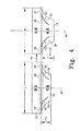
【0033】
図3は、図2に示したアダプタの実施形態の底面図である。図示した実施形態では、4個の足34が、アダプタ16の中心軸40から異なる方向に離れて延びるように等間隔に配置されている。他の実施形態では、より多い、又はより少ない足34を有してもよい。図示の実施形態の足34は、足34がスリット42によって分離される手前の領域にある遠方端44と、近傍端38とを有する。
【0034】
足34は更に、溶接部46を有する。図示の実施形態の溶接部46は一つの環状リングを形成し、このリングが、スリット42によってところどころ中断されている。他の実施形態では、足34の形状により、溶接部46は、ところどころ中断されている他の形状をなしていてもよい。図示の実施形態の溶接部46は、比較的平坦な表面であって、この表面が近傍端38から、中心軸40に対してほぼ垂直に、所定の距離だけ延びている。比較的平坦な表面は足34の一部であって、プラスチックの表面に対して、平行にそして接触するように配置されるように意図されている。ここで「比較的平坦」という言葉は、表面の大部分にわたって、溶融プラスチックに接触するように、十分に滑らかで連続的な表面形状(topography)を持つ表面を意味する。
【0035】
他の実施形態では、溶接部46が、近傍端38の近くの足34の予め決められた部分を中心軸40に向けて折り返して延びるように形成されている。この実施形態では、中心軸40に向かって延びる足34の部分がフランジを形成する。このフランジは溶接部46と、比較的平坦な表面を有する。比較的平坦な表面は、中心軸40に対してほぼ垂直であって、プラスチックの表面に対して、平行にそして接触するように配置されるように意図されている。更に他の実施形態では、溶接部46は、別個に形成されて、前述の複数の技術のいずれかによって足34と結合される。
【0036】
溶接部46はリップ48を有する。一つの実施形態では、リップ48は、各足34の近傍端38の近くに配置される。リップ48によって、プラスチックの表面への損傷を最小限にするべく、鋭利な端部をなくして滑らかで傷を付けない端部とすることができる。一つの実施形態では、リップ48は、足34の近傍端38の近くの部分を上方に前記比較的平坦な表面から離れる方向に曲げることによって形成される。他の実施形態では、リップ48は、各足34の端部を丸めることによって形成される。
【0037】
図1に最もよく示すように、図示の実施形態の溶接部46(図3)は、アダプタ16と、プラスチック燃料タンク12の内壁22の間の溶接境界面50を形成する。図1及び図3に示すように、溶接部46は、内壁22に対して比較的平坦な表面を向けている(presents)。溶接部46の比較的平坦な表面とリップ48とで、溶接境界面50のノッチ形状の生成が最小化される。足34が、プラスチックの表面に保持され、内壁22を形成するプラスチックの移動が最小化されるので、ノッチ形状の生成が最小化される。
【0038】
更に、溶接部46は、内壁22に大きな表面積を与える。この大きな表面積によって、その結果の溶接の安定性と強度が改善される。更に、その大きな表面積が、溶接工程の間に、アダプタ16が傾いたり、内面22から離れたりすることへの抵抗になる。
【0039】
アダプタ16が内壁22と接触するように動くとき、足34が内壁22に表面溶接される。表面溶接は、足34が、内壁22を形成する溶融プラスチックの表面に接して置かれたときに生じる。内壁22内に含まれていた熱が伝達されることによって、溶接部46内の足34の部分が溶融状態にまで加熱される。その後、溶接部46内の内壁22と足34が一緒に溶けて、溶接境界面50で剛性の接合を形成する。
【0040】
一つの実施形態では、溶接部46内の足34の厚さ(例えば低熱容量)によって、溶融状態は比較的急速に達成される。他の実施形態では、溶接部46内の足34の部分は、内壁22に配置する前に高温度まで予熱しておく。溶接部46の温度を、溶融状態を達成するのに必要な温度に近い温度にまで上げておくことによって、内壁22からの熱伝達に必要な時間を短縮することができる。足34は溶融状態にまでは予熱されないので、内壁22と接触する位置に置かれたときに、足34の形状は維持されている。更に、足34は次第に厚く(例えば次第に高熱容量に)なっているので、溶接部46の外側の足34の部分は、溶融状態に達していなくともよく、従って、溶接工程の最中に足34の形状が維持される。
【0041】
溶接境界面50が冷えるに従って、アダプタ16は、溶接境界面50に存在しうる応力の補償を提供する。応力は、例えば、内壁22と足34の異なる収縮によって生じうる。異なる収縮は、例えば、足34と内壁22の間の温度の違いによって生じうる。
【0042】
図4は、比較的「低温」にあると表示されたアダプタ16と、比較的「高温」に加熱されたと表示されていて溶融状態に達しているプラスチック片52とが結合した状態を模式的に示している。図示のように、プラスチック片52の長さはLで、アダプタ16の高さはHである。図4では更に、冷却工程も矢印54で示し、ここでは、プラスチック片52が比較的「低温」に冷却される一方で、アダプタ16は比較的「低温」に維持される。冷却の後に、プラスチック片52は、その冷却によって生じる収縮の結果、長さが(L−αL)になる。
【0043】
更に図4に示しているように、プラスチック片52の収縮によって生じる応力は、アダプタ16の柔軟性によって吸収される。より具体的には、アダプタ16の足34は、プラスチック52の横方向の動きに応じて曲がるだけの十分な柔軟性を有する。足34の曲がりによって、アダプタ16の全体高さは(H+ΔH)に増える。更に、図4に示し、図3の点線で示すように、足34の間のスリット42が狭くなり、溶接部46によってできる環状リングの直径は小さくなる。従って、プラスチック片52の表面と溶接部46との間の溶接境界面50に生じる局所応力は解放される。
【0044】
更に、プラスチック片52がプラスチック燃料タンク12(図1)である場合は、燃料が存在する場合の、プラスチック片52とアダプタ16の非均一な膨張によって引き起こされる局所応力も又、足34の柔軟な曲がりによって吸収される。更に、プラスチック燃料タンク12の動作中に他の条件で生じる応力も吸収されうる。そのような応力には、例えば、プラスチック燃料タンク系統(図1)内の非均一な加熱及び冷却による過渡的な熱的不均衡が含まれる。応力の原因のもう一つの例は、燃料系統コンポーネント14(図1)又はプラスチック燃料タンク12内の燃料の横方向の動きによって引き起こされる動的荷重である。中心軸40に平行でない方向の力がアダプタ16及びプラスチック片52に応力を与えるいずれの場合も、生じた応力を足34が吸収することができる。
【0045】
図1乃至4に示したように、上述のアダプタ16の実施形態では、プラスチックが溶融状態にあるときに、そのプラスチックに物体を固定的に結合することができる。アダプタ16は、比較的高い鉛直方向の剛性を提供すると同時に、アダプタ16とプラスチックの間に形成された溶接境界面50での応力を解放できるほどの横方向の柔軟性を提供する。更に、溶接境界面50は、疲労破壊の可能性を低下させると共に、プラスチックの表面の削減(compromise)を避けるための表面溶接になっている。アダプタ16は物体を永久的に取り付けるために、プラスチックの表面と共に、充分に強く安定な結合を作る。更に、アダプタ16は、プラスチックの表面に物体を固定的に結合するための取付け機構32を有する。
【0046】
一つの実施形態では、アダプタ16は、プラスチック燃料タンク12の製造段階で取り付けられると有利である。この実施形態では、アダプタ16は、燃料系統コンポーネント14を、プラスチック燃料タンク12の内壁22の表面に取り付ける。アダプタ16は、製造過程でプラスチック燃料タンク12の内側に配置され、炭化水素障壁を削る(compromise)ことなしに内壁22の表面に溶接される。従って、アダプタ16によって、燃料系統コンポーネント14を内部に配置し、プラスチック燃料タンク12内部からの燃料蒸気の漏れ及び/又は浸透を最小にすることができる。
【0047】
以上、種々の実施形態について本発明を説明したが、本発明の範囲から離れること無しに種々の変更や修正を加えることができることが理解できよう。例えば、アダプタ16は、複数の物を取り付けることも可能であり、又、二つのプラスチック表面の間を構造的に支持する機能を与えることも可能である。従って、以上の詳細な説明は、本発明の現時点での好ましい実施形態を示すものであって、発明の定義を意図するものではない。本発明の範囲を定義するものは特許請求の範囲の記載と、これと均等な範囲だけである。
【図面の簡単な説明】
【図1】アダプタの一実施形態の一応用例を示す図である。
【図2】図1に示すアダプタの斜視図である。
【図3】図2に示すアダプタの底面図である。
【図4】図2のアダプタの一応用例の側面図であって、アダプタの応力解放特性を示す。[0001]
【Technical field】
The present invention relates to the manufacture and molding of plastics, and in particular, to designs and processes for welding objects to plastic surfaces.
[Background Art]
Many types of rigid articles are made from plastic. These articles also include many articles in which objects are attached to a plastic surface. A well-known example of such an article is a plastic fuel tank. Plastic fuel tanks are used in land, water, and aviation transportation to store fuel for engines and other fuel consuming equipment. Plastic fuel tanks and other similar articles can be manufactured by blow molding or thermoforming techniques using high-density polyethylene (HDPE) plastic in the form of a single layer or compound injection. Plastic fuel tanks also have a hydrocarbon barrier that prevents fuel and associated vapors from passing through.
[0002]
To form a fuel system, multiple objects are typically added to a plastic fuel tank as multiple components of the fuel system. Components include, for example, valves, hoses, pumps, level sensors, structural supports, and the like. Typically, some of these components are installed inside the plastic fuel tank by providing service holes in the tank. In addition, some of the components are located outside the tank and require additional holes, grooves, and / or depressions.
[0003]
Recent changes in government regulations have reduced the allowance for the emission of fuel vapor from fuel tanks. One way to reduce the allowable fuel vapor emissions from plastic fuel tanks is to minimize hydrocarbon barrier destruction. Reducing the number of holes in the plastic fuel tank by placing the components of the fuel system inside minimizes destruction. In addition, placing the component on the inside will confine vapor emissions from the component itself within the hydrocarbon barrier. One way to place the components of the fuel system inside is to insert the components during the manufacture of the plastic tank.
[0004]
Components of the fuel system inserted during manufacturing can also be fixed to the inner wall of the plastic fuel tank when the wall is in a molten state. This mounting method is called a hot plate welding process. The process includes embedding a rigid bracket over the components in the interior wall. The step of heating the bracket with a hotplate to ensure adhesion between the bracket and the wall may be performed before contacting the inner wall. The bracket is a thick flat continuous plate or a flat plate with a waffle pattern thereon. The plate is partially or completely submerged in the molten plastic forming the wall. The components are held in place until the plastic fuel tank cools and the walls become rigid.
[0005]
As the plastic fuel tank cools, stresses may develop at the interface between the bracket and the inner wall due to the temperature difference between the inner wall and the bracket. In addition, non-uniform expansion resulting from the absorption of fuel by the brackets and inner walls may cause similar stresses when the plastic fuel tank holds fuel after manufacture. These stresses can also damage the bond formed between the bracket and the wall. Damage to the bond may lead to wall breakage and disengagement of fuel system components from the wall.
[0006]
Furthermore, during the manufacturing process in which the bracket is embedded in the inner wall, the material forming the wall is moved. The movement of material may lead to the destruction of thin points in the hydrocarbon barrier and / or walls. In addition, the displaced material creates a ridge or bead-like notch shape on the inner wall adjacent the bracket. This notch shape creates a discontinuity in the surface that should be continuous formed by the wall. This discontinuity creates a force perpendicular to the tension and compression forces in the wall. Thus, when the wall is subjected to a tensile or compressive load, damage to the mounting and / or inner wall may occur at the notch-shaped portion.
[0007]
Accordingly, there is a need for a method and system for attaching an object to a plastic surface that reduces the stress at the bond between the object and the plastic and does not compromise the structural integrity of the plastic.
[0008]
DISCLOSURE OF THE INVENTION
The present invention is defined by the appended claims, and should not be construed as limiting the scope of the claims. The embodiments described below include systems and methods that utilize an adapter for attaching an object to plastic when the plastic is in a molten state. The adapter can absorb not only the stress caused by external force but also the stress generated when the plastic and the adapter contract and expand independently. Further, the adapter is bonded to the plastic by surface welding. Surface welding minimizes the formation of notches and other structures that are detrimental to the integrity of the structure, while avoiding excessive plastic movement.
[0009]
The adapter has one body, one coupling mechanism, and at least two feet. The body connects the connection mechanism to the foot. The coupling mechanism couples the object to the adapter. The foot extends away from the body and has a weld that contacts the surface of the plastic. The weld is placed in contact with the surface of the plastic, heated, and reaches a molten state. When the molten state is reached, the weld and the surface of the plastic melt together to bond the object to the plastic.
[0010]
In one embodiment, the adapter couples at least one fuel system component to the plastic fuel tank wall so as to minimize holes or other breaks in the hydrocarbon barrier formed in the wall. In this embodiment, the adapter, together with the fuel system components coupled thereto, are brought into close contact with the surface of the wall when the wall is in a molten state. When the weld and wall of each foot are fused together, a weld interface is formed. The adapter not only minimizes the stress that occurs when the walls and feet cool, but also minimizes the stress that is generated when expansion in the presence of fuel occurs.
[0011]
One feature of the adapter is in the shape and operation of the foot. The foot is made of a flexible material and absorbs the stresses caused by independent contraction and expansion of the plastic and / or adapter, as well as the stresses caused by dynamic loading. In one embodiment, the foot is formed of a plastic resin and is formed gradually thinner toward the weld. The relatively thin portion of the foot of the weld quickly reaches a molten state due to its low heat capacity. Conversely, the relatively thick sections of the foot do not reach the molten state rapidly, and thus provide relatively solid structural support during installation and subsequent cooling.
[0012]
Another feature of the adapter is the weld. The weld on each foot has a relatively flat surface and lip. The relatively flat surface has a substantive surface that makes significant contact with the surface of the plastic. Due to the substantial contact by the solid surface, the adapter is held on its surface and, once welded, a strong connection is obtained. Further, the solid surface limits the depth of penetration of the adapter into the surface of the plastic and provides stability for objects coupled to the adapter. The lip avoids damaging the surface of the plastic by compromising the edge without causing harm. A non-harmful edge minimizes both the formation of the notch shape and the movement of the molten plastic forming its surface.
[0013]
Further features and advantages of the present invention are described below in connection with the preferred embodiments.
[0014]
BEST MODE FOR CARRYING OUT THE INVENTION
The embodiments disclosed herein have an adapter that allows objects to be attached to plastic. The adapter is flexible and rigid and strong enough to maintain the position of the object on plastic. The adapter is bonded to the plastic surface without significantly altering the surface topography. The flexibility of the adapter releases any stress that may occur at the joint between the adapter and the plastic. The adapter further has the ability to couple the object to the adapter, thereby allowing the object to be rigidly attached to the plastic. The adapter can be used in any application where the plastic is heated to a molten state and an object is bonded thereto.
[0015]
Here, the term "molten state" refers to a material in which the plastic is hot to a liquid state, is moldable, adaptable, pliable, and compatible. It is defined as a state in which joining by welding is possible.
[0016]
An example of the application of the adapter is in the field of plastic fuel tank systems. FIG. 1 shows one embodiment of a portion of a plastic fuel tank system 10. The plastic fuel tank system 10 includes plastic in one cross-section of a plastic fuel tank 12, at least one object that is a fuel system component 14, and at least one
[0017]
The plastic fuel tank 12 is a container having an inner wall 22 and an outer wall 24. The plastic fuel tank 12 is made of plastic or a plastic composite and typically has a hydrocarbon barrier to prevent hydrocarbon molecules from diffusing out of the plastic fuel tank 12. The plastic can be a single layer, a co-injection, a composite layer, or any other type of plastic formation.
[0018]
In one embodiment, the plastic is thermoplastic and comprises six layers. The first layer is the outer layer and includes high density polyethylene (HDPE) and carbon black. The second layer is adjacent to the inside of the first layer and includes a reground thermoplastic material. The third layer, adjacent to the second layer, is also an inner layer and includes a sticky polymer. The fourth layer is adjacent to the third layer and includes ethylene vinyl alcohol (EVOH). The EVOH layer of this embodiment provides a hydrocarbon barrier to reduce the emission of hydrocarbons through the thermoplastic. The fifth layer is adjacent to the fourth layer and includes a sticky polymer. The sixth layer is adjacent to the fifth layer and forms another outer layer and includes HDPE. In other embodiments, different configurations, arrangements and numbers of layers may be used to form the plastic.
[0019]
The plastic is formed in the plastic fuel tank 12 by a manufacturing process such as blow molding or two-sheet thermoforming. Blow molding uses a continuous injection process to make molten plastic. The molten plastic is injected as a hollow parison and formed in a mold. Two-sheet thermoforming is formed in a mold using a thermoplastic sheet that has been preformed and heated to a molten state.
[0020]
The fuel system component 14 may be any object mounted on or within the plastic fuel tank 12. Examples of fuel system components 14 include valves, hoses, pumps, cam lock rings, structural enhancements, and other fuel system related features and structures. In the illustrated embodiment, the fuel system component 14 is a valve having a fitting 26 and a hose 28 for delivering fuel through the valve. In other embodiments, the fuel system component 14 may be replaced by any other object.
[0021]
The
[0022]
In the illustrated embodiment, the fuel system components 14 and the
[0023]
FIG. 2 is a perspective view of one embodiment of the
[0024]
The
[0025]
The body 30 may be hollow or solid, and may have any shape as long as the position of the coupling mechanism 32 with respect to the
[0026]
In one embodiment, the body 30, the coupling mechanism 32, and the
[0027]
The coupling mechanism 32 may be of any coupling configuration for flexibly attaching an object, such as the fuel system component 14 (FIG. 1), to the
[0028]
The
[0029]
In the illustrated embodiment, the
[0030]
A portion of the body 30 adjacent to the
[0031]
In other embodiments,
[0032]
The
[0033]
FIG. 3 is a bottom view of the embodiment of the adapter shown in FIG. In the illustrated embodiment, the four
[0034]
The
[0035]
In another embodiment, the weld 46 is formed to extend a predetermined portion of the
[0036]
The weld 46 has a lip 48. In one embodiment, a lip 48 is located near the proximal end 38 of each
[0037]
As best shown in FIG. 1, the weld 46 (FIG. 3) of the illustrated embodiment forms a
[0038]
Further, the weld 46 provides a large surface area for the inner wall 22. This large surface area improves the stability and strength of the resulting weld. Further, the large surface area provides resistance to the
[0039]
As the
[0040]
In one embodiment, the molten state is achieved relatively quickly due to the thickness (eg, low heat capacity) of
[0041]
As
[0042]
FIG. 4 schematically shows a state in which the
[0043]
Further, as shown in FIG. 4, the stress caused by the shrinkage of the
[0044]
Furthermore, if the
[0045]
As shown in FIGS. 1-4, the above-described embodiment of the
[0046]
In one embodiment, the
[0047]
While the invention has been described with reference to various embodiments, it will be understood that various changes and modifications may be made without departing from the scope of the invention. For example, the
[Brief description of the drawings]
FIG. 1 is a diagram illustrating an application example of an embodiment of an adapter.
FIG. 2 is a perspective view of the adapter shown in FIG.
FIG. 3 is a bottom view of the adapter shown in FIG. 2;
FIG. 4 is a side view of one application of the adapter of FIG. 2, showing the stress release characteristics of the adapter.
Claims (37)
ボディ(30)と、
前記ボディと結合され、前記ボディから異なる方向に遠ざかるように延び、前記プラスチックの表面に溶接可能な、少なくとも2個の足(34)と、
前記ボディと結合された結合機構であって、前記物体を前記ボディに結合するように設けられた上記結合機構と、
を有することを特徴とするアダプタ。An adapter (16) for attaching an object to the plastic when the plastic is in a molten state, the adapter comprising:
A body (30),
At least two feet (34) coupled to the body, extending away from the body in different directions and weldable to the surface of the plastic;
A coupling mechanism coupled to the body, wherein the coupling mechanism is provided to couple the object to the body;
An adapter comprising:
それぞれが遠方端(44)と近傍端(38)とを有する複数のプラスチック製の足(34)と、
前記プラスチック製の各足の前記遠方端に接合されたボディ(30)であって、前記各足の前記近傍端が前記ボディから離れる方向に懸架されて、前記プラスチックの前記表面と係合するように溶接部(46)を形成する上記ボディと、
前記ボディと結合される結合機構(32)であって、前記物体と結合するように作用可能である上記結合機構と、
を有することを特徴とするアダプタ。An adapter (16) used to attach an object to plastic when the plastic is in a molten state, the adapter comprising:
A plurality of plastic feet (34) each having a distal end (44) and a proximal end (38);
A body (30) joined to the distal end of each plastic foot such that the proximal end of each foot is suspended away from the body to engage the surface of the plastic; Said body forming a weld (46) at
A coupling mechanism (32) coupled to the body, the coupling mechanism operable to couple to the object;
An adapter comprising:
遠方端(36)及び近傍端(38)を有して長手方向に延びる中空のハウジングを形成するボディ(30)を有し、
前記遠方端は前記燃料系統コンポーネントに結合するように作用可能な結合機構(32)を有し、
前記ボディには複数のスリット(42)があり、そのスリットは、前記近傍端から前記遠方端に向かって予め決められた距離だけ延びており、
前記スリットに隣接する前記ボディの一部が、前記近傍端の近くに溶接部(46)を提供するように形成され、その溶接部は、前記壁の前記表面に溶接可能であることを特徴とするアダプタ。An adapter (16) for attaching a fuel system component (14) to a plastic fuel tank (12) wall when the wall is in a molten state, the adapter comprising:
A body (30) having a distal end (36) and a proximal end (38) to form a longitudinally extending hollow housing;
The distal end has a coupling mechanism operable to couple to the fuel system component;
The body has a plurality of slits (42), the slits extending from the near end toward the far end by a predetermined distance,
A portion of the body adjacent to the slit is formed to provide a weld near the proximal end, the weld being weldable to the surface of the wall. Adapter to do.
b)ボディ(30)と複数の足(34)と結合機構(32)とを有するアダプタ(16)を提供する工程と、
c)前記結合機構に物体を結合する工程と、
d)前記足を前記プラスチックの表面に接触させて表面溶接を形成する工程と、
e)前記プラスチックと前記アダプタとを冷却する工程と、
を有することを特徴とするプラスチックに物体を結合する方法。a) heating the plastic to a molten state;
b) providing an adapter (16) having a body (30), a plurality of feet (34), and a coupling mechanism (32);
c) coupling an object to the coupling mechanism;
d) contacting the foot with a surface of the plastic to form a surface weld;
e) cooling the plastic and the adapter;
A method of bonding an object to plastic, comprising:
g)前記プラスチック及び前記足の独立の膨張によって生じる応力を吸収する工程と、を有する請求項28又は29記載の方法。And f) applying a fuel to the plastic and the adapter;
g) absorbing stresses caused by independent expansion of the plastic and the foot.
前記アダプタを中空円筒ハウジングとして形成する工程と、
前記足を前記中空円筒ハウジングの一部として形成する工程と、
を有する請求項28記載の方法。The step b) comprises:
Forming the adapter as a hollow cylindrical housing;
Forming the feet as part of the hollow cylindrical housing;
29. The method of claim 28, comprising:
Applications Claiming Priority (2)
| Application Number | Priority Date | Filing Date | Title |
|---|---|---|---|
| US22448700P | 2000-08-11 | 2000-08-11 | |
| PCT/US2001/024274 WO2002014041A2 (en) | 2000-08-11 | 2001-08-03 | Adapter for welding objects to plastic |
Publications (2)
| Publication Number | Publication Date |
|---|---|
| JP2004505812A true JP2004505812A (en) | 2004-02-26 |
| JP2004505812A5 JP2004505812A5 (en) | 2005-01-06 |
Family
ID=22840919
Family Applications (3)
| Application Number | Title | Priority Date | Filing Date |
|---|---|---|---|
| JP2002519213A Pending JP2004512211A (en) | 2000-08-11 | 2001-08-03 | Hydrocarbon low emission fuel tank with internal components |
| JP2002519173A Abandoned JP2004505814A (en) | 2000-08-11 | 2001-08-03 | Mass production of low-permeability plastic fuel tanks using twin-sheet parallel offset pressure molding |
| JP2002519164A Abandoned JP2004505812A (en) | 2000-08-11 | 2001-08-03 | Adapter for welding objects to plastic |
Family Applications Before (2)
| Application Number | Title | Priority Date | Filing Date |
|---|---|---|---|
| JP2002519213A Pending JP2004512211A (en) | 2000-08-11 | 2001-08-03 | Hydrocarbon low emission fuel tank with internal components |
| JP2002519173A Abandoned JP2004505814A (en) | 2000-08-11 | 2001-08-03 | Mass production of low-permeability plastic fuel tanks using twin-sheet parallel offset pressure molding |
Country Status (6)
| Country | Link |
|---|---|
| US (3) | US6726967B2 (en) |
| EP (3) | EP1307332B1 (en) |
| JP (3) | JP2004512211A (en) |
| BR (3) | BR0107088A (en) |
| DE (1) | DE60110431D1 (en) |
| WO (3) | WO2002014041A2 (en) |
Cited By (5)
| Publication number | Priority date | Publication date | Assignee | Title |
|---|---|---|---|---|
| JP2008524054A (en) * | 2004-12-15 | 2008-07-10 | イネルジー オートモーティヴ システムズ リサーチ | Method for manufacturing plastic fuel tank with improved creep strength |
| JP2014037146A (en) * | 2006-02-10 | 2014-02-27 | Kautex Textron Gmbh & Co Kg | Production method of plastic hollow body equipped with built-in parts |
| JP2015120513A (en) * | 2009-04-23 | 2015-07-02 | イナジー・オートモーティブ・システムズ・リサーチ・(ソシエテ・アノニム) | Plastic fuel tank with improved creep resistance and method for manufacturing thereof |
| US9796260B2 (en) | 2014-10-17 | 2017-10-24 | Toyota Jidosha Kabushiki Kaisha | Fuel tank |
| US10370143B2 (en) | 2006-07-03 | 2019-08-06 | Kautex Textron Gmbh & Co. Kg | Container of thermoplastic material |
Families Citing this family (66)
| Publication number | Priority date | Publication date | Assignee | Title |
|---|---|---|---|---|
| US6372176B1 (en) * | 1999-03-01 | 2002-04-16 | Kiefel Technologies Inc. | System and method for twin sheet forming |
| US6943678B2 (en) * | 2000-01-24 | 2005-09-13 | Nextreme, L.L.C. | Thermoformed apparatus having a communications device |
| US8077040B2 (en) | 2000-01-24 | 2011-12-13 | Nextreme, Llc | RF-enabled pallet |
| US7342496B2 (en) * | 2000-01-24 | 2008-03-11 | Nextreme Llc | RF-enabled pallet |
| US6661339B2 (en) | 2000-01-24 | 2003-12-09 | Nextreme, L.L.C. | High performance fuel tank |
| FR2806959B1 (en) * | 2000-04-03 | 2003-02-14 | Plastic Omnium Cie | METHOD FOR MANUFACTURING A BLOWER THERMOPLASTIC TANK INCORPORATING AN INSERT |
| DE10064218A1 (en) * | 2000-12-22 | 2002-07-11 | Kiefel Gmbh Paul | Method and device for the production of hollow bodies |
| US20030136507A1 (en) * | 2002-01-18 | 2003-07-24 | Thiel Steven A. | Thermoformed fuel tank fuel delivery system and assembly method |
| DE10219280B4 (en) * | 2002-04-30 | 2015-04-09 | Bayerische Motoren Werke Aktiengesellschaft | oil tank |
| GB2389086B (en) * | 2002-05-14 | 2005-12-14 | Aquafactors Direct Ltd | Modular cleaning system |
| US6969246B1 (en) | 2002-07-24 | 2005-11-29 | Brown Machine, Llc | Forming station and process for twin sheet thermoforming |
| DE10260953B4 (en) * | 2002-12-20 | 2010-07-01 | Kautex Textron Gmbh & Co Kg | Fuel tank with functional component carrier and carrier for functional components of a motor vehicle fuel tank |
| ITMI20030027A1 (en) | 2003-01-10 | 2004-07-11 | Cannon Spa | THERMOFORMING IN DOUBLE PLATE OF TANKS IN PLASTIC MATERIAL. |
| US7045086B2 (en) * | 2003-03-13 | 2006-05-16 | Soroc Products, Inc. | Twinsheet thermoforming system and method |
| US7913712B2 (en) | 2004-01-21 | 2011-03-29 | Raval A.C.S. Ltd. | Fuel accessory for fuel tank and method for internally attaching same |
| US7389789B2 (en) * | 2004-01-21 | 2008-06-24 | Raval-Agriculture Cooperative Societies Ltd. | Fuel accessory for fuel tank and method for internally attaching same |
| US8381928B2 (en) | 2004-06-04 | 2013-02-26 | Ti Group Automotive Systems, L.L.C. | Multilayer fuel tank with a seam having an overlay for reducing vapor permeation |
| DE102004034906A1 (en) * | 2004-07-19 | 2006-02-16 | Geiss Ag | Method and device for producing a hollow body containing at least one insert part |
| FR2873321B1 (en) * | 2004-07-23 | 2008-05-09 | Inergy Automotive Systems Res | METHOD FOR FIXING AN ACCESSORY IN A FUEL TANK OF PLASTIC MATERIAL |
| DE602005024653D1 (en) * | 2004-08-27 | 2010-12-23 | Mitsubishi Gas Chemical Co | Method for producing hollow bodies |
| US7455190B2 (en) * | 2004-11-15 | 2008-11-25 | Automotive Components Holdings, Llc | Fuel tank system having enhanced durability and reduced permeation |
| US8470235B2 (en) | 2006-02-03 | 2013-06-25 | Inergy Automotive Systems Research | Process and equipment for manufacturing a fuel tank provided with internal accessories |
| GB2438646A (en) * | 2006-05-30 | 2007-12-05 | Motorola Inc | System for content item recommendation |
| WO2008007352A2 (en) * | 2006-07-12 | 2008-01-17 | Raval A.C.S. Ltd. | Venting tubing system for a fuel tank |
| US7648103B2 (en) * | 2006-12-13 | 2010-01-19 | EMBRAER—Empresa Brasileira de Aeronautica S.A. | Aircraft fuel tanks, systems and methods for increasing an aircraft's on-board fuel capacity |
| US7861885B2 (en) * | 2006-12-15 | 2011-01-04 | Kautex Textron Gmbh & Co. Kg | Fuel tank of thermoplastic material with functional installation fitments for air intake and venting, for fuel take-off or the like |
| US7829819B2 (en) * | 2007-02-08 | 2010-11-09 | Automotive Components Holdings, Llc | Attaching a component to an internal surface of a tank formed of polymer |
| DE102007028881B4 (en) * | 2007-06-20 | 2014-07-10 | Kautex Textron Gmbh & Co. Kg | Process for the production of hollow bodies made of thermoplastic material |
| FR2934805A1 (en) * | 2008-08-07 | 2010-02-12 | Inergy Automotive Systems Res | METHOD FOR ATTACHING AN ACCESSORY TO A HOLLOW BODY OF PLASTIC MATERIAL DURING MOLDING |
| FR2934806A1 (en) * | 2008-08-07 | 2010-02-12 | Inergy Automotive Systems Res | METHOD FOR ATTACHING AN ACCESSORY IN A HOLLOW BODY OF PLASTIC MATERIAL |
| FR2934804A1 (en) * | 2008-08-07 | 2010-02-12 | Inergy Automotive Systems Res | PROCESS FOR THE MANUFACTURE OF A FUEL TANK OF PLASTIC MATERIAL. |
| FR2935289B1 (en) * | 2008-09-01 | 2013-02-22 | Inergy Automotive Systems Res | PROCESS FOR THE MANUFACTURE OF A FUEL TANK OF PLASTIC PLASTIC MATERIAL WITH PUMP. |
| US8105068B2 (en) * | 2008-11-05 | 2012-01-31 | Spirit Aerosystems, Inc. | Reusable infusion bag |
| JP5293095B2 (en) * | 2008-11-07 | 2013-09-18 | 三菱自動車工業株式会社 | Fuel tank |
| CN101823425B (en) * | 2009-01-22 | 2014-05-21 | 麦格纳斯太尔燃油系统公司 | Fuel tank having installations and method for the production thereof |
| EP2391491A2 (en) * | 2009-01-30 | 2011-12-07 | LRM Industries International, Inc. | Method of forming a molded article from thermoformable thermoplastic sheets |
| CN101633240B (en) * | 2009-08-19 | 2011-07-20 | 亚普汽车部件有限公司 | Forming method of blow molding hollow box body capable of internally provided with assembly and preformed molding plate device |
| US8287270B2 (en) * | 2009-09-30 | 2012-10-16 | Printpack Illinois Inc. | Methods and systems for thermoforming with billets |
| US8377368B2 (en) * | 2009-12-11 | 2013-02-19 | Ti Automotive Technology Center Gmbh | Component mounting arrangement |
| JP5495873B2 (en) * | 2010-03-16 | 2014-05-21 | 株式会社Fts | Automotive fuel tank |
| DE102010018527A1 (en) * | 2010-04-27 | 2011-10-27 | Kautex Textron Gmbh & Co. Kg | Process for the production of hollow bodies made of thermoplastic material |
| ES2553280T3 (en) | 2010-05-06 | 2015-12-07 | Salflex Polymers Ltd. | Fuel tank for vehicles |
| US9994101B2 (en) | 2010-05-06 | 2018-06-12 | Jeff Yager | Vehicle fuel tank |
| US9321347B2 (en) * | 2010-06-14 | 2016-04-26 | Ford Global Technologies, Llc | Compliance structure for a distensible fuel tank |
| DE102010032279B4 (en) * | 2010-07-26 | 2012-09-06 | Kautex Textron Gmbh & Co. Kg | Method of riveting an accessory |
| PL2646349T3 (en) | 2010-12-03 | 2017-07-31 | Yfs Automotive Systems Inc. | Deployable fuel tank baffle and fuel tank system |
| DE102011011631B4 (en) * | 2011-02-17 | 2014-10-16 | Continental Automotive Gmbh | Tank device for storing a liquid pollutant-reducing medium |
| US9027781B2 (en) * | 2011-04-12 | 2015-05-12 | Inergy Automotive Systems Research (Sociate Anonyme) | Fuel tank with improved mechanical resistance |
| JP5907078B2 (en) * | 2013-01-15 | 2016-04-20 | トヨタ自動車株式会社 | Fuel tank structure |
| WO2014122747A1 (en) * | 2013-02-07 | 2014-08-14 | 株式会社Fts | Automobile fuel tank |
| JP5807661B2 (en) * | 2013-06-14 | 2015-11-10 | トヨタ自動車株式会社 | Fuel tank |
| EP2827039A1 (en) * | 2013-07-17 | 2015-01-21 | Volvo Car Corporation | Quick connector |
| JP5969442B2 (en) * | 2013-09-02 | 2016-08-17 | 八千代工業株式会社 | Manufacturing apparatus and manufacturing method for hollow molded article |
| EP2857645B2 (en) * | 2013-10-02 | 2019-01-09 | Magna Steyr Fuel Systems GmbH | Container for urea solution and method for manufacturing such a container |
| US9120450B1 (en) | 2014-05-29 | 2015-09-01 | Ford Global Technologies, Llc | Active bolster with spine reinforced weld track |
| FR3026044B1 (en) * | 2014-09-18 | 2017-06-23 | Centre Technique Des Ind Mec | HOT-SHAPING PROCESS OF THERMOPLASTIC MATERIAL AND INSTALLATION FOR IMPLEMENTING THE SAME |
| DE102014222286B4 (en) | 2014-10-31 | 2024-07-18 | Kautex Textron Gmbh & Co. Kg | Operating fluid container for a motor vehicle made of thermoplastic material |
| DE102014019645B4 (en) | 2014-12-24 | 2016-10-06 | Bernd Hillerich | Photoionization detector with stabilized UV source |
| DE102015217763B4 (en) * | 2015-09-16 | 2021-02-25 | Röchling Automotive SE & Co. KG | Tank for storage and delivery of liquids with functional components arranged on the tank wall |
| DE102016219539A1 (en) * | 2016-10-07 | 2018-04-12 | Kautex Textron Gmbh & Co. Kg | Stiffening element for a fluid container for a motor vehicle and fluid container for a motor vehicle with a stiffening element |
| EP3595853A4 (en) * | 2017-03-16 | 2020-12-23 | Guerrilla Industries LLC | Composite structures and methods of forming composite structures |
| DE102017223124A1 (en) * | 2017-12-18 | 2019-06-19 | Röchling Automotive SE & Co. KG | Multi-part injection-molded multi-chamber plastic tank with sloping joining surface |
| KR101937183B1 (en) * | 2018-02-14 | 2019-01-11 | (주)동희산업 | Baffle with supporter |
| CN109572411A (en) * | 2018-12-12 | 2019-04-05 | 重庆久和豪贝机械有限公司 | A kind of automotive oil tank |
| US11572124B2 (en) | 2021-03-09 | 2023-02-07 | Guerrilla Industries LLC | Composite structures and methods of forming composite structures |
| WO2022266391A1 (en) * | 2021-06-17 | 2022-12-22 | Raven Industries, Inc. | Flexible storage tank |
Family Cites Families (36)
| Publication number | Priority date | Publication date | Assignee | Title |
|---|---|---|---|---|
| US3462330A (en) | 1965-12-09 | 1969-08-19 | Woodall Industries Inc | Method for making a hollow plastic core structure |
| GB1160779A (en) * | 1967-07-25 | 1969-08-06 | Ici Ltd | Improvements in the production of Shaped Articles from Blanks of Thermosplastics Material |
| GB1242509A (en) * | 1968-01-25 | 1971-08-11 | Conrad Goldman | Thermoforming of thermoplastic polymers |
| US3647335A (en) * | 1969-04-11 | 1972-03-07 | Packaging Ind Inc | Apparatus for forming containers |
| US4452943A (en) * | 1971-09-10 | 1984-06-05 | Conrad Goldman | Thermoforming of thermoplastic polymers |
| CA993165A (en) * | 1971-11-22 | 1976-07-20 | Peter T. Schurman | Plastic article and blow molding method and apparatus |
| DE2600582A1 (en) | 1976-01-09 | 1977-07-14 | Kiefel Gmbh Paul | Two-step heating of thermoplastics film or sheet - by first contact heating to below shaping temp. and then by e.g. infrared radiation to shaping temp. |
| BR7601340A (en) * | 1976-03-05 | 1977-09-06 | M Coelho | IMPROVEMENTS ON THERMOFORMING MACHINES |
| GB2048163B (en) * | 1977-11-16 | 1982-05-19 | Broadhurst J C Fletcher R A | Flexible self-sealing wall member |
| US4431404A (en) * | 1982-08-26 | 1984-02-14 | Whirlpool Corporation | Method and apparatus for heating plastic sheet material |
| JPS62213156A (en) | 1986-03-14 | 1987-09-19 | Hitachi Ltd | Charge transfer type solid-state image pickup element |
| US4790972A (en) * | 1986-05-16 | 1988-12-13 | Rampart Packaging Inc. | Method for stacking billets and thermoforming |
| JPS6456532A (en) * | 1987-08-28 | 1989-03-03 | Excel Corp | Structure of additional part of hollow molded product with additional part |
| JP2537660B2 (en) * | 1988-05-28 | 1996-09-25 | 豊田合成株式会社 | Manufacturing method of synthetic resin fuel tank |
| EP0366129B1 (en) * | 1988-10-28 | 1993-10-27 | Sotralentz S.A. | Method for the manufacture of a bung barrel with a side wall, bottom and cover |
| EP0415109B1 (en) * | 1989-07-31 | 1995-09-20 | Yamamura Glass Co. Ltd. | Bottle neck structure and manufacturing method therefor |
| DE3941992A1 (en) * | 1989-12-20 | 1991-06-27 | Tetra Pak Gmbh | METHOD FOR PRODUCING A FLUID PACK AND USING A PLASTIC PLATE FOR THE MANUFACTURING METHOD |
| US5389177A (en) * | 1990-10-31 | 1995-02-14 | Shuert; Lyle H. | Thermoforming process for making a twin sheet plastic structure including captured metallic element |
| US5129544A (en) | 1990-11-08 | 1992-07-14 | Jacobson Wendell L | Laminated fuel tank structure |
| US5269251A (en) * | 1991-10-03 | 1993-12-14 | Continental Safety Supply Co. | Traffic safety control system and method |
| DE4203705A1 (en) * | 1992-02-08 | 1993-08-12 | Kautex Werke Gmbh | METHOD FOR PRODUCING HOLLOW BODIES FROM THERMOPLASTIC PLASTIC AND HOLLOW BODIES FROM THERMOPLASTIC PLASTIC |
| DE69424125T2 (en) * | 1993-11-18 | 2000-09-21 | Siemens Automotive Corp., Auburn Hills | Installation adapter for fuel injector with auxiliary air |
| US5547096A (en) * | 1994-12-21 | 1996-08-20 | Kleyn Die Engravers, Inc. | Plated polymeric fuel tank |
| AU5341296A (en) * | 1995-05-01 | 1996-11-21 | Korpak Limited | Cutting and creasing apparatus |
| US5658523A (en) * | 1995-06-06 | 1997-08-19 | Shuert; Lyle H. | Method and apparatus for forming twin sheet hollow plastic articles |
| US5961914A (en) * | 1996-05-03 | 1999-10-05 | Milliken & Company | Method of thermoforming polyolefin resin |
| US5788794A (en) | 1996-05-23 | 1998-08-04 | Pepsico, Inc. | Method for producing a partitioned bottle |
| US6193924B1 (en) | 1996-08-28 | 2001-02-27 | Moeller Marine Products | Storage tank assembly |
| DE19641751B4 (en) * | 1996-10-10 | 2009-07-09 | Evonik Degussa Gmbh | Two-part connecting element |
| JP3597664B2 (en) * | 1997-03-14 | 2004-12-08 | 株式会社東芝 | Method of manufacturing magnetic head |
| BE1012079A3 (en) * | 1998-07-22 | 2000-04-04 | Solvay | Welding machine hollow objects and method for welding these objects. |
| US6294114B1 (en) * | 1998-08-20 | 2001-09-25 | Scott A. W. Muirhead | Triple sheet thermoforming apparatus, methods and articles |
| US6372176B1 (en) * | 1999-03-01 | 2002-04-16 | Kiefel Technologies Inc. | System and method for twin sheet forming |
| US6138859A (en) * | 1999-06-08 | 2000-10-31 | Delphi Technologies, Inc. | Fuel tank assembly |
| US6379606B1 (en) * | 1999-11-17 | 2002-04-30 | Brown Machine, Llc. | Method for thermoforming twin sheet workpiece |
| US6395357B1 (en) * | 1999-12-18 | 2002-05-28 | Delphi Technologies, Inc. | Fuel permeation barrier fuel tank |
-
2001
- 2001-08-03 EP EP01961895A patent/EP1307332B1/en not_active Expired - Lifetime
- 2001-08-03 BR BR0107088-6A patent/BR0107088A/en not_active IP Right Cessation
- 2001-08-03 WO PCT/US2001/024274 patent/WO2002014041A2/en not_active Application Discontinuation
- 2001-08-03 DE DE60110431T patent/DE60110431D1/en not_active Expired - Lifetime
- 2001-08-03 EP EP01957403A patent/EP1309436A2/en not_active Withdrawn
- 2001-08-03 BR BR0107087-8A patent/BR0107087A/en not_active IP Right Cessation
- 2001-08-03 JP JP2002519213A patent/JP2004512211A/en active Pending
- 2001-08-03 WO PCT/US2001/024528 patent/WO2002014050A2/en active IP Right Grant
- 2001-08-03 US US09/921,607 patent/US6726967B2/en not_active Expired - Fee Related
- 2001-08-03 BR BR0107075-4A patent/BR0107075A/en not_active Application Discontinuation
- 2001-08-03 US US09/922,059 patent/US6969485B2/en not_active Expired - Fee Related
- 2001-08-03 US US09/921,541 patent/US20020020705A1/en not_active Abandoned
- 2001-08-03 JP JP2002519173A patent/JP2004505814A/en not_active Abandoned
- 2001-08-03 JP JP2002519164A patent/JP2004505812A/en not_active Abandoned
- 2001-08-03 EP EP01961893A patent/EP1307355A2/en not_active Withdrawn
- 2001-08-03 WO PCT/US2001/024525 patent/WO2002014097A2/en not_active Application Discontinuation
Cited By (11)
| Publication number | Priority date | Publication date | Assignee | Title |
|---|---|---|---|---|
| JP2008524054A (en) * | 2004-12-15 | 2008-07-10 | イネルジー オートモーティヴ システムズ リサーチ | Method for manufacturing plastic fuel tank with improved creep strength |
| JP2012158392A (en) * | 2004-12-15 | 2012-08-23 | Inergy Automotive Systems Research (Sa) | Method for manufacturing plastic fuel tank with improved creep strength |
| US8663544B2 (en) | 2004-12-15 | 2014-03-04 | Inergy Automotive Systems Research (Societe Anonyme) | Method for manufacturing a plastic fuel tank with improved creep strength |
| US9440403B2 (en) | 2004-12-15 | 2016-09-13 | Inergy Automotive Systems Research (Société Anonyme) | Method for manufacturing a plastic fuel tank with improved creep strength |
| US9452577B2 (en) | 2004-12-15 | 2016-09-27 | Inergy Automotive Systems Research (Societe Anonyme) | Method for manufacturing a plastic fuel tank with improved creep strength |
| US9764507B2 (en) | 2004-12-15 | 2017-09-19 | Inergy Automotive Systems Research (Societe Anonyme) | Method for manufacturing a plastic fuel tank with improved creep strength |
| US10369736B2 (en) | 2004-12-15 | 2019-08-06 | Plastic Omnium Advanced Innovation And Research | Method for manufacturing a plastic fuel tank with improved creep strength |
| JP2014037146A (en) * | 2006-02-10 | 2014-02-27 | Kautex Textron Gmbh & Co Kg | Production method of plastic hollow body equipped with built-in parts |
| US10370143B2 (en) | 2006-07-03 | 2019-08-06 | Kautex Textron Gmbh & Co. Kg | Container of thermoplastic material |
| JP2015120513A (en) * | 2009-04-23 | 2015-07-02 | イナジー・オートモーティブ・システムズ・リサーチ・(ソシエテ・アノニム) | Plastic fuel tank with improved creep resistance and method for manufacturing thereof |
| US9796260B2 (en) | 2014-10-17 | 2017-10-24 | Toyota Jidosha Kabushiki Kaisha | Fuel tank |
Also Published As
| Publication number | Publication date |
|---|---|
| JP2004505814A (en) | 2004-02-26 |
| WO2002014050A3 (en) | 2002-05-02 |
| WO2002014041A2 (en) | 2002-02-21 |
| EP1309436A2 (en) | 2003-05-14 |
| US20020017745A1 (en) | 2002-02-14 |
| BR0107088A (en) | 2002-06-18 |
| EP1307332A2 (en) | 2003-05-07 |
| US20020020705A1 (en) | 2002-02-21 |
| US6726967B2 (en) | 2004-04-27 |
| EP1307355A2 (en) | 2003-05-07 |
| WO2002014097A3 (en) | 2002-05-10 |
| WO2002014050A2 (en) | 2002-02-21 |
| US20020020487A1 (en) | 2002-02-21 |
| WO2002014041A3 (en) | 2002-05-16 |
| JP2004512211A (en) | 2004-04-22 |
| WO2002014097A2 (en) | 2002-02-21 |
| EP1307332B1 (en) | 2005-04-27 |
| DE60110431D1 (en) | 2005-06-02 |
| BR0107087A (en) | 2002-06-18 |
| US6969485B2 (en) | 2005-11-29 |
| BR0107075A (en) | 2002-07-16 |
Similar Documents
| Publication | Publication Date | Title |
|---|---|---|
| JP2004505812A (en) | Adapter for welding objects to plastic | |
| JP3623191B2 (en) | Low-permeability accessory, low-permeability container using the accessory, and method for manufacturing the container | |
| JP6871479B2 (en) | Liquid containers for motor vehicles and methods for manufacturing liquid containers | |
| KR101529347B1 (en) | Process for manufacturing a plastic fuel tank | |
| US20060151505A1 (en) | Fuel tank for motor vehicle and method for producing the same | |
| US20110226777A1 (en) | Fuel tank for motor vehicle | |
| US20170246790A1 (en) | Manufacturing process for filler tube | |
| US20150217635A1 (en) | Automobile fuel tank | |
| US8973778B2 (en) | Self-adjusting connector | |
| CA2657920C (en) | Hose and tubing assemblies and mounting systems and methods | |
| JP2008507651A (en) | How to connect accessories to a plastic fuel tank | |
| US10195936B2 (en) | Filler tube and manufacturing process for the same | |
| US10596744B2 (en) | Method for welding a heat shield during manufacturing of a vehicle component | |
| US20070181582A1 (en) | System for fastening two components, method of fastening by means of this fastening system, and fuel system | |
| US20150239198A1 (en) | Attaching structure of insert member to blow molded article | |
| CN102137746A (en) | Process for manufacturing a plastic fuel tank equipped with a pump | |
| JP2020531741A (en) | Liquid containers and methods for manufacturing liquid containers | |
| US6793870B1 (en) | Method for linking two plastic components | |
| JP2013119342A (en) | Component welding structure of fuel tank | |
| JPH01316244A (en) | Blow molded product and its manufacture | |
| JP6788939B2 (en) | How to install the filler pipe | |
| KR102361463B1 (en) | Plug for fuel tank | |
| LU502042B1 (en) | Reinforced storage tank for a vehicle | |
| JPS5850744Y2 (en) | container | |
| US20040144779A1 (en) | Mounting clip for plastic containers |
Legal Events
| Date | Code | Title | Description |
|---|---|---|---|
| A762 | Written abandonment of application |
Free format text: JAPANESE INTERMEDIATE CODE: A762 Effective date: 20050405 |
|
| A521 | Request for written amendment filed |
Free format text: JAPANESE INTERMEDIATE CODE: A523 Effective date: 20050510 |