JP2004363262A - Device and method for processing picked-up image of electronic-part mounting machine - Google Patents
Device and method for processing picked-up image of electronic-part mounting machine Download PDFInfo
- Publication number
- JP2004363262A JP2004363262A JP2003158768A JP2003158768A JP2004363262A JP 2004363262 A JP2004363262 A JP 2004363262A JP 2003158768 A JP2003158768 A JP 2003158768A JP 2003158768 A JP2003158768 A JP 2003158768A JP 2004363262 A JP2004363262 A JP 2004363262A
- Authority
- JP
- Japan
- Prior art keywords
- suction
- component
- pixels
- suction nozzle
- electronic component
- Prior art date
- Legal status (The legal status is an assumption and is not a legal conclusion. Google has not performed a legal analysis and makes no representation as to the accuracy of the status listed.)
- Granted
Links
Images


Abstract
Description
【0001】
【発明の属する技術分野】
本発明は、吸着ノズルに吸着した電子部品をカメラで撮像してその撮像画像データに基づいて該電子部品の外観情報及び/又は吸着位置情報を検出するようにした電子部品実装機の撮像画像処理装置及び撮像画像処理方法に関するものである。
【0002】
【従来の技術】
一般に、電子部品実装機は、吸着ノズルにおける電子部品の吸着異常を検出する機能を備えている。電子部品の吸着異常の態様には、例えば、不良部品の吸着、異なる部品の吸着、部品の立ち吸着、吸着ミスによる吸着部品無しがある。吸着ノズルに吸着した電子部品をカメラで撮像する場合は、カメラの撮像画像から取り込んだ吸着部品の外観情報に基づいて不良部品や異なる部品を検出するようにしているが、従来の画像処理技術では撮像画像から吸着部品無しの状態を認識することはできなかった。
【0003】
そのため、従来は、吸着ノズルの真空吸引系に真空センサを設けて、吸着ノズルの部品吸着動作後の真空度を真空センサで検出して、その真空度によって吸着部品の有無を判定するようにしている。
【0004】
しかしながら、小径の吸着ノズルを使用する場合は、吸着部品有りと吸着部品無しの場合で、真空度の差が小さくなるため、吸着部品の有無を正確に判定できない。また、部品が立ち吸着されている場合は、吸着ノズルの先端から真空漏れが発生することがあるため、部品の立ち吸着を吸着部品無しと誤判定する可能性がある。
【0005】
このような問題を解決するために、特許文献1(特開2000−136904号公報)に記載されているように、吸着ノズルに吸着した電子部品を反射光照明により撮像して電子部品を画像認識し、その結果、吸着異常と認識された場合には、反射光照明を透過光照明に切り換えて、再度、画像認識して、吸着部品の有無を判定するようにしたものがある。
【0006】
【特許文献1】
特開2000−136904号公報(第2頁〜第3頁等)
【0007】
【発明が解決しようとする課題】
しかしながら、上記特許文献1の電子部品実装機では、反射光照明と透過光照明の2種類の照明装置が必要となるため、照明装置のコストが高くなると共に、照明装置の設置スペースを2箇所に確保する必要があり、照明装置全体の構成が大型化する欠点がある。
【0008】
本発明はこのような事情を考慮してなされたものであり、従ってその目的は、既存の電子部品実装機に対して、ソフトウェア(プログラム)の追加又は変更のみで吸着ノズルの吸着部品の有無を判定する機能を持たせることができる電子部品実装機の撮像画像処理装置及び撮像画像処理方法を提供することにある。
【0009】
【課題を解決するための手段】
上記目的を達成するために、本発明は、予め、吸着ノズルに電子部品を吸着していない状態で該吸着ノズル及びその周囲の背景部分をカメラで撮像して得られた撮像画像(以下「吸着部品無し背景画像」という)に基づいてマスク処理値を設定して記憶手段に記憶しておき、吸着ノズルの部品吸着動作後にカメラの撮像画像を取り込み、該撮像画像の各ピクセル(画素)の輝度を前記マスク処理値と比較して、該マスク処理値以上の輝度のピクセル数(反射光照明の場合)又は該マスク処理値以下の輝度のピクセル数(透過光照明の場合)に基づいて該吸着ノズルの吸着部品の有無を判定するようにしたものである。
【0010】
一般に、カメラ付きの電子部品実装機では、反射光照明を用い、カメラの撮像画像に写る吸着ノズル及びその周囲の背景部分を黒色に着色することで、電子部品の画像とそれ以外の背景画像とを区別しやすいようにしている。従って、予め、吸着ノズルに電子部品を吸着していない状態を撮像して得られた吸着部品無し背景画像に基づいてマスク処理値を設定しておけば、撮像画像の各ピクセルの輝度を前記マスク処理値と比較して、該マスク処理値以上の輝度のピクセル数(反射光照明の場合)又は該マスク処理値以下の輝度のピクセル数(透過光照明の場合)を計数することで、吸着部品の画像の面積(吸着部品の大きさ)に比例するピクセル数を求めることができ、吸着部品の有無を精度良く判定することができる。これにより、既存の電子部品実装機に対して、ソフトウェア(プログラム)の追加又は変更のみで吸着ノズルの吸着部品の有無を判定する機能を持たせることができる。
【0011】
この場合、予め、吸着部品無し背景画像のピクセルの輝度の頻度分布を表す輝度ヒストグラムを作成して、その輝度ヒストグラムに基づいて前記マスク処理値を設定するようにすると良い。このようにすれば、輝度ヒストグラムによってノイズ等を排除することができ、マスク処理値の精度を高めることができる。
【0012】
更に、輝度ヒストグラムの近似式の曲線が頻度0の線と交わる輝度を前記マスク処理値として設定するようにすると良い。このようにすれば、撮像画像に写る吸着ノズル及びその周囲の背景部分をマスキングするためのマスク処理値を精度良く設定することができる。
【0013】
また、吸着部品有りと判断する最小のピクセル数を、吸着ノズルで吸着可能な最小の電子部品を立ち吸着したときの撮像画像に基づいて設定するようにすると良い。このようにすれば、吸着ノズルに小さなごみ等が吸着されたときに、ごみ等を吸着部品と誤判定することを回避することができる。
【0014】
また、カメラの撮像画像のピクセルを間引きしてサンプリングするようにしても良い。つまり、吸着部品の有無を検出する際には、吸着部品の形状を正確に認識する必要はなく、ある程度大雑把に認識できれば良いため、吸着部品の外観情報を正確に認識する場合よりも少ないピクセル数で吸着部品を認識すれば良い。このため、吸着部品の有無を検出する際の画像処理時に、間引き処理を行うことが可能となり、それによって、コンピュータの演算速度を高速化し、且つ、演算負荷を軽減することができる。
【0015】
【発明の実施の形態】
以下、本発明の一実施形態を図面に基づいて説明する。本発明は、吸着ノズルに吸着した電子部品を撮像するカメラを備えた電子部品実装機であれば、そのシステム構成を問わず、全ての機種に適用できるため、電子部品実装機の機械的構成の説明は省略する。尚、カメラを備えた電子部品実装機の一例は、例えば特開2000−294990号公報に記載されている。
【0016】
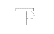
本実施形態の電子部品実装機では、反射光照明を用い、カメラの撮像画像に写る吸着ノズル11及びその周囲の背景部分12(バックプレート等)を黒色に着色している。
【0017】
次に、撮像画像に写る吸着ノズル11及びその周囲の背景部分12をマスキングするためのマスク処理値を設定する方法を説明する。まず、吸着ノズル11に電子部品を吸着していない状態で該吸着ノズル11及びその周囲の背景部分12をカメラで撮像して、吸着部品無し背景画像を取得する。
【0018】
この後、この吸着部品無し背景画像のピクセル(画素)の輝度の頻度分布を表す輝度ヒストグラムを作成する(図3参照)。この際、吸着部品無し背景画像の全てのピクセルをサンプリングして全てのピクセルに関する輝度ヒストグラムを作成しても良いが、吸着部品無し背景画像のピクセルを1個おきに間引きしてサンプリングすることで、サンプリング数を1/2に減らしても良い。
【0019】
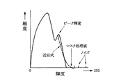
図3に示すように、輝度ヒストグラムは、横軸(X軸)の目盛りを輝度0から255までの256階調(8ビットの場合)とし、縦軸(Y軸)の目盛りを頻度とする。ノイズを除去するために、頻度が例えば5未満を切り捨てる。つまり、頻度が5未満は、頻度0とみなす。輝度ヒストグラムには、2つのピークが出来る。一方のピークは、吸着ノズル11の周囲の背景部分12(バックプレート等)の画像によるピークであり、他方のピークは、吸着ノズル11の画像によるピークである。
【0020】
そして、輝度ヒストグラムの2つのピークのうち輝度が大きい方のピークを検索する。この際、輝度ヒストグラムが輝度100以下の領域に分布することを考慮して、例えば、輝度100から降順に頻度が落ち込むピーク輝度を求める。
【0021】
この後、求めたピーク輝度から次の二次元多項式の近似式を求める(図3における2点鎖線)。
Y=aX2 +bX+c
Y:頻度
X:輝度
a,b,c:係数
【0022】
尚、二次元多項式に限定されず、1次元多項式又は3次元以上の多項式でも良い。要は、輝度ヒストグラムの近似式が得られれば良い。本実施形態では、二次元多項式の近似式を用いるものとする。
【0023】
この後、輝度ヒストグラムの二次元多項式の近似式の曲線が頻度0(Y=0)の線と交わる輝度Xを求め、これをマスク処理値として設定する。このマスク処理値は、画像処理を行うコンピュータの記憶装置(記憶手段)に記憶される。
【0024】
二次元多項式の近似式の曲線が頻度0の線と交わる輝度X(マスク処理値)は二次方程式(aX2 +bX+c=0)の解の公式から算出すれば良い。
【0025】
【数1】

上記解の公式から輝度Xを算出する場合、近似式の曲線が頻度0(Y=0)の線と交わらない場合があるので、二次方程式の判別式(b2 −4ac)がプラス値であるか否かで、輝度X(マスク処理値)を算出可能か否かを判定する。もし、判別式(b2 −4ac)がマイナス値であれば、輝度Xを算出不能(解なし)と判断して、マスク処理値の設定エラーとする。
【0027】
次に、吸着部品有りと判断する最小のピクセル数(判定ピクセル数)の設定方法を説明する。本実施形態では、吸着部品有りと判断する最小のピクセル数(判定ピクセル数)を、吸着ノズル11で吸着可能な最小の電子部品を立ち吸着したときの撮像画像に基づいて設定する。以下、これを具体的に説明する。
【0028】
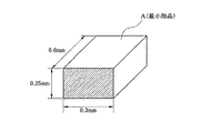
吸着ノズル11で吸着可能な最小の電子部品Aのサイズを、図4に示すように0.6mm×0.3mm×0.25mmとする。正常な吸着状態では、部品Aの0.6mm×0.3mmの面が撮像されるが、立ち吸着状態では、部品Aの最小面(0.3mm×0.25mmの面)が撮像される。
【0029】
1ピクセルの大きさ(ユニット値)が例えば40μmの場合の部品Aの最小面の画像のピクセル数は、縦:0.25mm/40μm=6.25(ピクセル)であり、横:0.3mm/40μm=7.5(ピクセル)である。従って、部品Aの最小面の画像の総ピクセル数は、6.25×7.5=46.875(ピクセル)となる。本実施形態では、部品Aの最小面の画像のピクセルを1個おきに間引きしてサンプリングするため、部品Aの最小面の画像の総ピクセル数は、面積で1/4に相当する12(ピクセル)となる。この12(ピクセル)が判定ピクセル数となる。この判定ピクセル数は、画像処理を行うコンピュータの記憶装置(記憶手段)に記憶される。
【0030】
吸着ノズル11の部品吸着動作後にカメラの撮像画像を1ピクセルおきに間引きしてサンプリングし、マスク処理値以上の輝度のピクセル数が判定ピクセル数以上存在すれば、吸着部品有りと判定し、判定ピクセル数未満であれば、吸着部品無しと判定する。尚、判定ピクセル数は、1ピクセルの大きさ(ユニット値)から求めるので、カメラの分解能の違いによって異なってくる。
【0031】
以上説明した吸着部品有無の判定は、画像処理を行うコンピュータによって図5のプログラムに従って実行される。本プログラムは、吸着ノズル11の部品吸着動作後に起動され、まず、ステップ101で、カメラの撮像画像を1ピクセルおきに間引きしてサンプリングする。この後、ステップ102に進み、サンプリングしたピクセルの中に、マスク処理値以上の輝度のピクセルが存在するか否かを判定し、マスク処理値以上の輝度のピクセルが存在しなければ、ステップ108に進み、吸着部品無しと判定する。この場合は、ステップ107に進み、再度、吸着ノズル11の部品吸着動作を繰り返す。
【0032】
一方、ステップ102でマスク処理値以上の輝度のピクセルが存在すると判定された場合は、ステップ103に進み、マスク処理値以上の輝度のピクセル数が判定ピクセル数以上であるか否かを判定する。もし、マスク処理値以上の輝度のピクセル数が判定ピクセル数未満であれば、吸着ノズル11で吸着可能な最小の電子部品Aよりも小さいごみ等を撮像したものと判断して、ステップ108に進み、吸着部品無しと判定し、再度、吸着ノズル11の部品吸着動作を繰り返す(ステップ107)。
【0033】
これに対して、マスク処理値以上の輝度のピクセル数が判定ピクセル数以上存在すれば、ステップ104に進み、吸着部品有りと判定する。この場合は、ステップ105に進み、画像処理による部品認識が正常に行われたか否かを判定し、部品認識が正常に行われなかった場合(例えば不良部品の吸着、異なる部品の吸着の場合)は、ステップ109に進み、吸着ノズル11に吸着されている部品を所定の廃棄場所に廃棄する。
【0034】
上記ステップ105で、部品認識が正常に行われたと判定されれば、ステップ106に進み、吸着ノズル11に吸着されている部品を回路基板の所定位置に実装する。この後、ステップ107に進み、吸着ノズル11に新たな電子部品を吸着する。
【0035】
以上説明した本実施形態によれば、予め、吸着ノズル11に電子部品を吸着していない状態で該吸着ノズル11及びその周囲の背景部分12をカメラで撮像して得られた吸着部品無し背景画像に基づいてマスク処理値を設定しておき、吸着ノズル11の部品吸着動作後にカメラの撮像画像を取り込み、該撮像画像の各ピクセルの輝度を前記マスク処理値と比較して、該マスク処理値以上の輝度のピクセル数が判定ピクセル数以上であるか否かで、該吸着ノズル11の吸着部品の有無を判定するようにしたので、既存の電子部品実装機に対して、ソフトウェア(プログラム)の追加又は変更のみで吸着ノズル11の吸着部品の有無を判定する機能を持たせることができる。
【0036】
しかも、マスク処理値を設定する際に、吸着部品無し背景画像のピクセルの輝度の頻度分布を表す輝度ヒストグラムを作成して、その輝度ヒストグラムに基づいて前記マスク処理値を設定するようにしたので、輝度ヒストグラムによってノイズ等を排除することができ、撮像画像に写る吸着ノズル11及びその周囲の背景部分12をマスキングするためのマスク処理値を精度良く設定することができる。
【0037】
また、吸着部品有りと判断する最小のピクセル数(判定ピクセル数)を、吸着ノズル11で吸着可能な最小の電子部品Aを立ち吸着したときの撮像画像に基づいて設定するようにしたので、吸着ノズル11に小さなごみ等が吸着されたときに、ごみ等を吸着部品と誤判定することを回避することができる。
【0038】
また、本実施形態では、吸着部品の有無を検出する際に、吸着部品の外観情報を正確に認識する場合よりも少ないピクセル数で吸着部品を認識すれば良いということに着目して、カメラの撮像画像のピクセルを間引きしてサンプリングするようにしたので、コンピュータの演算速度を高速化し、且つ、演算負荷を軽減することができる利点もある。
しかしながら、本発明は、間引き処理を行わず、撮像画像の全てのピクセルの輝度をサンプリングするようにしても良いことは言うまでもない。
【0039】
また、本実施形態では、反射光照明を用いて吸着部品を撮像するようにしたが、透過光照明を用いて吸着部品を撮像するシステムにも本発明を適用することができる。透過光照明を用いる場合は、反射光照明の場合とは反対に、吸着部品の画像が黒色(輝度0)となり、それ以外の部分の輝度が大きくなるため、マスク処理値以下の輝度のピクセル数が判定ピクセル数以上であるか否かで、該吸着ノズル11の吸着部品の有無を判定するようにすれば良い。
【0040】
また、本発明による吸着部品有無の判定と真空センサによる吸着部品有無の判定とを併用して、判定精度を更に高めるようにしても良い。
【図面の簡単な説明】
【図1】本発明の一実施形態における吸着ノズルとその周囲の背景部分(バックプレート等)を概略的に示す正面図
【図2】吸着部品無し背景画像を概略的に示す図
【図3】輝度ヒストグラムを示す図
【図4】吸着ノズルで吸着可能な最小の電子部品のサイズを説明する斜視図
【図5】吸着部品有無判定プログラムの処理の流れを示すフローチャート
【符号の説明】
11…吸着ノズル、12…背景部分(バックプレート等)。[0001]
TECHNICAL FIELD OF THE INVENTION
The present invention relates to a picked-up image processing of an electronic component mounting machine which picks up an electronic component sucked by a suction nozzle with a camera and detects appearance information and / or suction position information of the electronic component based on the picked-up image data. The present invention relates to an apparatus and a captured image processing method.
[0002]
[Prior art]
Generally, an electronic component mounting machine has a function of detecting a suction abnormality of an electronic component in a suction nozzle. Examples of the abnormal suction state of the electronic component include suction of a defective component, suction of a different component, standing suction of a component, and absence of a suction component due to a suction error. When an electronic component picked up by a suction nozzle is imaged by a camera, a defective component or a different component is detected based on appearance information of the picked-up component captured from an image captured by the camera. It was not possible to recognize the state without the suction component from the captured image.
[0003]
Therefore, conventionally, a vacuum sensor is provided in the vacuum suction system of the suction nozzle, the degree of vacuum after the component suction operation of the suction nozzle is detected by the vacuum sensor, and the presence or absence of the suction component is determined based on the vacuum degree. I have.
[0004]
However, when a small-diameter suction nozzle is used, the difference in the degree of vacuum between the case with the suction component and the case without the suction component is small, so that the presence or absence of the suction component cannot be accurately determined. In addition, when a component is standing and sucked, a vacuum leak may occur from the tip of the suction nozzle, and there is a possibility that the standing suction of the component is erroneously determined to be no suction component.
[0005]
In order to solve such a problem, as described in Patent Document 1 (Japanese Patent Application Laid-Open No. 2000-136904), an electronic component adsorbed on a suction nozzle is imaged by reflected light illumination to recognize the electronic component. However, as a result, when it is recognized that the suction abnormality is detected, the reflected light illumination is switched to the transmitted light illumination, the image is recognized again, and the presence or absence of the suction component is determined.
[0006]
[Patent Document 1]
JP-A-2000-136904 (pages 2 to 3 etc.)
[0007]
[Problems to be solved by the invention]
However, the electronic component mounting machine disclosed in Patent Document 1 requires two types of illumination devices: reflected light illumination and transmitted light illumination, so that the cost of the illumination device is increased and the installation space for the illumination device is reduced to two places. However, there is a disadvantage that the configuration of the entire lighting device becomes large.
[0008]
The present invention has been made in view of such circumstances, and accordingly, the object is to determine the presence or absence of a suction component of a suction nozzle in an existing electronic component mounting machine only by adding or changing software (program). An object of the present invention is to provide a captured image processing device and a captured image processing method of an electronic component mounting machine that can have a determination function.
[0009]
[Means for Solving the Problems]
In order to achieve the above object, the present invention relates to a picked-up image (hereinafter referred to as a “sucking image”) obtained by picking up an image of a suction nozzle and a background portion around the suction nozzle in a state where the electronic component is not sucked by the suction nozzle. A mask processing value is set based on the “partless background image” and stored in the storage unit, and the captured image of the camera is captured after the component suction operation of the suction nozzle, and the luminance of each pixel (pixel) of the captured image is captured. Is compared with the mask processing value, and the adsorption is performed based on the number of pixels having a luminance equal to or greater than the mask processing value (in the case of reflected light illumination) or the number of pixels having a luminance equal to or less than the mask processing value (in the case of transmitted light illumination). The presence or absence of the suction component of the nozzle is determined.
[0010]
In general, an electronic component mounting machine with a camera uses reflected light illumination to color the suction nozzle and the background around it in an image captured by the camera black, so that the image of the electronic component and the other background image can be combined. Are easy to distinguish. Therefore, if a mask processing value is set in advance based on a background image without a suction component obtained by imaging a state in which an electronic component is not suctioned by the suction nozzle, the brightness of each pixel of the captured image can be reduced by the mask. The number of pixels having a luminance equal to or higher than the mask processing value (in the case of reflected light illumination) or the number of pixels having a luminance equal to or less than the mask processing value (in the case of transmitted light illumination) is compared with the processing value, so that the suction component is obtained. The number of pixels proportional to the area of the image (the size of the suction component) can be obtained, and the presence or absence of the suction component can be determined with high accuracy. This allows the existing electronic component mounter to have a function of determining the presence or absence of the suction component of the suction nozzle only by adding or changing software (program).
[0011]
In this case, it is preferable that a luminance histogram representing the frequency distribution of the luminance of the pixels of the background image without a suction component is created in advance, and the mask processing value is set based on the luminance histogram. In this way, noise and the like can be eliminated by the luminance histogram, and the accuracy of the mask processing value can be improved.
[0012]
Further, it is preferable to set the luminance at which the curve of the approximate expression of the luminance histogram intersects the line with the frequency of 0 as the mask processing value. In this way, it is possible to accurately set the mask processing value for masking the suction nozzles and the surrounding background portion in the captured image.
[0013]
Further, it is preferable that the minimum number of pixels for determining that there is a suction component is set based on an image picked up when the smallest electronic component that can be suctioned by the suction nozzle is stuck. With this configuration, when small dust or the like is sucked by the suction nozzle, it is possible to avoid erroneous determination of the dust or the like as a suction component.
[0014]
Alternatively, sampling may be performed by thinning out the pixels of the image captured by the camera. In other words, when detecting the presence or absence of a suction component, it is not necessary to accurately recognize the shape of the suction component, and it is sufficient to be able to roughly recognize the shape to some extent. What is necessary is just to recognize a suction component by. For this reason, it is possible to perform the thinning process at the time of the image processing for detecting the presence or absence of the suction component, thereby increasing the calculation speed of the computer and reducing the calculation load.
[0015]
BEST MODE FOR CARRYING OUT THE INVENTION
Hereinafter, an embodiment of the present invention will be described with reference to the drawings. The present invention can be applied to all types of electronic component mounting machines, regardless of the system configuration, as long as the electronic component mounting machine is equipped with a camera for imaging the electronic components sucked by the suction nozzle. Description is omitted. An example of an electronic component mounter equipped with a camera is described in, for example, JP-A-2000-294990.
[0016]
In the electronic component mounter of this embodiment, the reflected light illumination is used, and the
[0017]
Next, a method of setting a mask processing value for masking the
[0018]
Thereafter, a brightness histogram representing the frequency distribution of the brightness of the pixels of the background image without suction components is created (see FIG. 3). At this time, all the pixels of the background image without the suction component may be sampled to create a luminance histogram for all the pixels. However, by sampling and sampling every other pixel of the background image without the suction component, The number of samplings may be reduced to half.
[0019]
As shown in FIG. 3, in the luminance histogram, the scale on the horizontal axis (X axis) is 256 gradations (in the case of 8 bits) from
[0020]
Then, of the two peaks of the luminance histogram, the peak having the higher luminance is searched. At this time, in consideration of the fact that the luminance histogram is distributed in an area having a luminance of 100 or less, for example, a peak luminance whose frequency decreases in descending order from the luminance 100 is obtained.
[0021]
Thereafter, an approximate expression of the following two-dimensional polynomial is obtained from the obtained peak luminance (two-dot chain line in FIG. 3).
Y = aX 2 + bX + c
Y: frequency X: luminance a, b, c: coefficient
Note that the present invention is not limited to a two-dimensional polynomial, and may be a one-dimensional polynomial or a three-dimensional or higher polynomial. The point is that an approximate expression of the luminance histogram may be obtained. In the present embodiment, an approximate expression of a two-dimensional polynomial is used.
[0023]
Thereafter, the luminance X at which the curve of the approximate expression of the two-dimensional polynomial of the luminance histogram intersects the line of frequency 0 (Y = 0) is obtained, and this is set as a mask processing value. The mask processing value is stored in a storage device (storage unit) of a computer that performs image processing.
[0024]
The luminance X (mask processing value) at which the curve of the approximate expression of the two-dimensional polynomial intersects the line of
[0025]
(Equation 1)
When calculating the luminance X from the formula of the above solution, since the curve of the approximate expression may not intersect with the line of frequency 0 (Y = 0), the discriminant of the quadratic equation (b 2 -4ac) is a plus value. It is determined whether or not the luminance X (mask processing value) can be calculated based on the presence or absence. If discriminant (b 2 -4ac) is equal negative value, it is determined impossible calculates the luminance X (no solution), the setting error of the masking values.
[0027]
Next, a method for setting the minimum number of pixels (determined pixel number) for determining that there is a suction component will be described. In the present embodiment, the minimum number of pixels for determining that there is a suction component (the number of determination pixels) is set based on the captured image when the smallest electronic component that can be suctioned by the
[0028]
The minimum size of the electronic component A that can be sucked by the
[0029]
When the size (unit value) of one pixel is, for example, 40 μm, the number of pixels of the image of the minimum surface of the component A is vertical: 0.25 mm / 40 μm = 6.25 (pixel), and horizontal: 0.3 mm / 40 μm = 7.5 (pixel). Therefore, the total number of pixels of the image of the minimum surface of the component A is 6.25 × 7.5 = 46.875 (pixels). In the present embodiment, since the pixels of the image of the minimum surface of the component A are thinned out every other pixel and sampled, the total number of pixels of the image of the minimum surface of the component A is 12 (pixels) corresponding to 1/4 in area. ). This 12 (pixels) is the number of determination pixels. This determination pixel number is stored in a storage device (storage unit) of the computer that performs the image processing.
[0030]
After the component suction operation of the
[0031]
The determination of the presence or absence of the suction component described above is performed by a computer that performs image processing according to the program in FIG. This program is started after the component suction operation of the
[0032]
On the other hand, if it is determined in
[0033]
On the other hand, if the number of pixels having a luminance equal to or greater than the mask processing value is equal to or greater than the number of determination pixels, the process proceeds to step 104, where it is determined that a suction component is present. In this case, the process proceeds to step 105, where it is determined whether or not the component recognition by the image processing has been normally performed. If the component recognition has not been normally performed (for example, a defective component is suctioned, or a different component is suctioned). Proceeds to step 109, and discards the component sucked by the
[0034]
If it is determined in
[0035]
According to the present embodiment described above, a suction component-less background image obtained by imaging the
[0036]
In addition, when setting the mask processing value, a luminance histogram representing the frequency distribution of the luminance of the pixels of the background image without the suction component is created, and the mask processing value is set based on the luminance histogram. Noise and the like can be eliminated by the luminance histogram, and a mask processing value for masking the
[0037]
In addition, the minimum number of pixels (the number of determined pixels) for determining that there is a suction component is set based on an image captured when the smallest electronic component A that can be suctioned by the
[0038]
Further, in the present embodiment, when detecting the presence / absence of a suction component, it is necessary to recognize the suction component with a smaller number of pixels than when accurately recognizing the appearance information of the suction component. Since sampling is performed by thinning out pixels of the captured image, there is an advantage that the calculation speed of the computer can be increased and the calculation load can be reduced.
However, in the present invention, it is needless to say that the luminance of all the pixels of the captured image may be sampled without performing the thinning process.
[0039]
Further, in the present embodiment, the suction component is imaged using the reflected light illumination. However, the present invention can be applied to a system that captures the suction component using the transmitted light illumination. When the transmitted light illumination is used, contrary to the case of the reflected light illumination, the image of the suction component becomes black (luminance 0) and the luminance of the other parts is increased. The presence or absence of the suction component of the
[0040]
In addition, the determination of the presence or absence of the suction component according to the present invention and the determination of the presence or absence of the suction component using the vacuum sensor may be used together to further enhance the determination accuracy.
[Brief description of the drawings]
FIG. 1 is a front view schematically illustrating a suction nozzle and a background portion (a back plate and the like) around the suction nozzle according to an embodiment of the present invention. FIG. 2 is a diagram schematically illustrating a background image without a suction component. FIG. 4 is a diagram illustrating a luminance histogram. FIG. 4 is a perspective view illustrating the size of the smallest electronic component that can be suctioned by a suction nozzle. FIG. 5 is a flowchart illustrating a processing flow of a suction component presence / absence determination program.
11: suction nozzle, 12: background part (back plate, etc.).
Claims (9)
前記吸着ノズルに電子部品を吸着していない状態で該吸着ノズル及びその周囲の背景部分を前記カメラで撮像して得られた撮像画像(以下「吸着部品無し背景画像」という)に基づいて予め設定されたマスク処理値を記憶する記憶手段と、
前記吸着ノズルの部品吸着動作後に前記カメラの撮像画像を取り込み、該撮像画像の各ピクセルの輝度を前記マスク処理値と比較して、該マスク処理値以上の輝度のピクセル数又は該マスク処理値以下の輝度のピクセル数に基づいて該吸着ノズルの吸着部品の有無を判定する吸着部品有無判定手段と
を備えていることを特徴とする電子部品実装機の撮像画像処理装置。In a picked-up image processing apparatus of an electronic component mounting machine for picking up an electronic component sucked by a suction nozzle with a camera and detecting appearance information and / or suction position information of the electronic component based on the picked-up image data,
Preliminarily set based on a captured image (hereinafter, referred to as a “background image without a suction component”) obtained by imaging the suction nozzle and a background portion around the suction nozzle in a state where the electronic component is not suctioned by the suction nozzle. Storage means for storing the mask processing value obtained,
After the component suction operation of the suction nozzle, the captured image of the camera is captured, and the brightness of each pixel of the captured image is compared with the mask processing value, and the number of pixels having a brightness equal to or greater than the mask processing value or equal to or less than the mask processing value A pick-up component presence / absence determining means for determining the presence / absence of a suction component of the suction nozzle based on the number of pixels having a luminance of the picked-up nozzle.
予め、前記吸着ノズルに電子部品を吸着していない状態で該吸着ノズル及びその周囲の背景部分を前記カメラで撮像して得られた撮像画像(以下「吸着部品無し背景画像」という)に基づいてマスク処理値を設定して記憶手段に記憶しておき、
前記吸着ノズルの部品吸着動作後に前記カメラの撮像画像を取り込み、該撮像画像の各ピクセルの輝度を前記マスク処理値と比較して、該マスク処理値以上の輝度のピクセル数又は該マスク処理値以下の輝度のピクセル数に基づいて該吸着ノズルの吸着部品の有無を判定することを特徴とする電子部品実装機の撮像画像処理方法。In a picked-up image processing method of an electronic component mounting machine for picking up an electronic component sucked by a suction nozzle with a camera and detecting appearance information and / or suction position information of the electronic component based on the picked-up image data,
In advance, based on a captured image (hereinafter, referred to as a “sucking component-less background image”) obtained by imaging the suction nozzle and a background portion around the suction nozzle in a state where the electronic component is not sucked by the suction nozzle. Set the mask processing value and store it in the storage means,
After the component suction operation of the suction nozzle, the captured image of the camera is captured, and the brightness of each pixel of the captured image is compared with the mask processing value, and the number of pixels having a brightness equal to or greater than the mask processing value or equal to or less than the mask processing value A method for determining the presence or absence of a suction component of the suction nozzle based on the number of pixels having a brightness of the picked-up nozzle.
Priority Applications (1)
| Application Number | Priority Date | Filing Date | Title |
|---|---|---|---|
| JP2003158768A JP4255115B2 (en) | 2003-06-04 | 2003-06-04 | Captured image processing apparatus and captured image processing method for electronic component mounter |
Applications Claiming Priority (1)
| Application Number | Priority Date | Filing Date | Title |
|---|---|---|---|
| JP2003158768A JP4255115B2 (en) | 2003-06-04 | 2003-06-04 | Captured image processing apparatus and captured image processing method for electronic component mounter |
Publications (2)
| Publication Number | Publication Date |
|---|---|
| JP2004363262A true JP2004363262A (en) | 2004-12-24 |
| JP4255115B2 JP4255115B2 (en) | 2009-04-15 |
Family
ID=34052012
Family Applications (1)
| Application Number | Title | Priority Date | Filing Date |
|---|---|---|---|
| JP2003158768A Expired - Lifetime JP4255115B2 (en) | 2003-06-04 | 2003-06-04 | Captured image processing apparatus and captured image processing method for electronic component mounter |
Country Status (1)
| Country | Link |
|---|---|
| JP (1) | JP4255115B2 (en) |
Cited By (5)
| Publication number | Priority date | Publication date | Assignee | Title |
|---|---|---|---|---|
| JP2009508361A (en) * | 2005-09-14 | 2009-02-26 | サイバーオプティクス コーポレーション | Pick and place machine with improved component pick image processing |
| JP2012235056A (en) * | 2011-05-09 | 2012-11-29 | Fuji Mach Mfg Co Ltd | Detecting method of sucked object in suction nozzle of component fitting head and component fitting device |
| JP2013021196A (en) * | 2011-07-13 | 2013-01-31 | Fuji Mach Mfg Co Ltd | Image processing apparatus of component mounting machine |
| JP2013202699A (en) * | 2012-03-27 | 2013-10-07 | Disco Corp | Presence or absence determination method for plate workpiece |
| CN114073178A (en) * | 2019-07-23 | 2022-02-18 | 株式会社富士 | Data management device |
-
2003
- 2003-06-04 JP JP2003158768A patent/JP4255115B2/en not_active Expired - Lifetime
Cited By (6)
| Publication number | Priority date | Publication date | Assignee | Title |
|---|---|---|---|---|
| JP2009508361A (en) * | 2005-09-14 | 2009-02-26 | サイバーオプティクス コーポレーション | Pick and place machine with improved component pick image processing |
| JP4896136B2 (en) * | 2005-09-14 | 2012-03-14 | サイバーオプティクス コーポレーション | Pick and place machine with improved component pick image processing |
| JP2012235056A (en) * | 2011-05-09 | 2012-11-29 | Fuji Mach Mfg Co Ltd | Detecting method of sucked object in suction nozzle of component fitting head and component fitting device |
| JP2013021196A (en) * | 2011-07-13 | 2013-01-31 | Fuji Mach Mfg Co Ltd | Image processing apparatus of component mounting machine |
| JP2013202699A (en) * | 2012-03-27 | 2013-10-07 | Disco Corp | Presence or absence determination method for plate workpiece |
| CN114073178A (en) * | 2019-07-23 | 2022-02-18 | 株式会社富士 | Data management device |
Also Published As
| Publication number | Publication date |
|---|---|
| JP4255115B2 (en) | 2009-04-15 |
Similar Documents
| Publication | Publication Date | Title |
|---|---|---|
| US6748104B1 (en) | Methods and apparatus for machine vision inspection using single and multiple templates or patterns | |
| JP5680976B2 (en) | Electronic blackboard system and program | |
| US7813559B2 (en) | Image analysis for pick and place machines with in situ component placement inspection | |
| CN111656883B (en) | Learning completion model generation system and method for component image recognition | |
| JP2005072888A (en) | Image projection method and image projection device | |
| US10721849B2 (en) | Component data handling device and component mounting system | |
| JP2010261955A (en) | Head loading component alignment using many area array type image detectors | |
| CN112084964A (en) | Product identification apparatus, method and storage medium | |
| CN115524347A (en) | Defect detection method, defect detection apparatus, and computer-readable storage medium | |
| JP2004363262A (en) | Device and method for processing picked-up image of electronic-part mounting machine | |
| JP2019036015A (en) | Surface mounting machine | |
| KR101126759B1 (en) | Method of teaching for electronic parts information in chip mounter | |
| KR100213345B1 (en) | Apparatus for adjusting adjustable component and method for detecting adjusting groove | |
| JP3123275B2 (en) | Inspection data creation method for electronic parts shortage inspection | |
| JP2004325146A (en) | Method and device for recognizing part | |
| CN111536895A (en) | Shape recognition device, shape recognition system, and shape recognition method | |
| JPH0797015B2 (en) | Position correction method of SMD by image processing | |
| JPH05215513A (en) | Image center measuring apparatus and fitting apparatus using same | |
| KR100213346B1 (en) | Apparatus and method for detecting adjusting groove of adjustable component | |
| JP2000276592A (en) | Method and device for detecting fault | |
| JPH0677695A (en) | Method and device for detecting abnormal suction of component of component packaging machine | |
| JP2001174221A (en) | Method and device for detecting position of component | |
| JPH1166326A (en) | Method and device for recognizing pattern | |
| KR20160107474A (en) | Method for compensating component image | |
| JPH0658741A (en) | Detection method for part inclination |
Legal Events
| Date | Code | Title | Description |
|---|---|---|---|
| A621 | Written request for application examination |
Free format text: JAPANESE INTERMEDIATE CODE: A621 Effective date: 20060412 |
|
| A131 | Notification of reasons for refusal |
Free format text: JAPANESE INTERMEDIATE CODE: A131 Effective date: 20081112 |
|
| A977 | Report on retrieval |
Free format text: JAPANESE INTERMEDIATE CODE: A971007 Effective date: 20081112 |
|
| A521 | Request for written amendment filed |
Free format text: JAPANESE INTERMEDIATE CODE: A523 Effective date: 20081225 |
|
| TRDD | Decision of grant or rejection written | ||
| A01 | Written decision to grant a patent or to grant a registration (utility model) |
Free format text: JAPANESE INTERMEDIATE CODE: A01 Effective date: 20090126 |
|
| A01 | Written decision to grant a patent or to grant a registration (utility model) |
Free format text: JAPANESE INTERMEDIATE CODE: A01 |
|
| A61 | First payment of annual fees (during grant procedure) |
Free format text: JAPANESE INTERMEDIATE CODE: A61 Effective date: 20090126 |
|
| FPAY | Renewal fee payment (event date is renewal date of database) |
Free format text: PAYMENT UNTIL: 20120206 Year of fee payment: 3 |
|
| R150 | Certificate of patent or registration of utility model |
Ref document number: 4255115 Country of ref document: JP Free format text: JAPANESE INTERMEDIATE CODE: R150 Free format text: JAPANESE INTERMEDIATE CODE: R150 |
|
| FPAY | Renewal fee payment (event date is renewal date of database) |
Free format text: PAYMENT UNTIL: 20120206 Year of fee payment: 3 |
|
| FPAY | Renewal fee payment (event date is renewal date of database) |
Free format text: PAYMENT UNTIL: 20130206 Year of fee payment: 4 |
|
| R250 | Receipt of annual fees |
Free format text: JAPANESE INTERMEDIATE CODE: R250 |
|
| FPAY | Renewal fee payment (event date is renewal date of database) |
Free format text: PAYMENT UNTIL: 20130206 Year of fee payment: 4 |
|
| FPAY | Renewal fee payment (event date is renewal date of database) |
Free format text: PAYMENT UNTIL: 20140206 Year of fee payment: 5 |
|
| R250 | Receipt of annual fees |
Free format text: JAPANESE INTERMEDIATE CODE: R250 |
|
| R250 | Receipt of annual fees |
Free format text: JAPANESE INTERMEDIATE CODE: R250 |
|
| R250 | Receipt of annual fees |
Free format text: JAPANESE INTERMEDIATE CODE: R250 |
|
| R250 | Receipt of annual fees |
Free format text: JAPANESE INTERMEDIATE CODE: R250 |
|
| R250 | Receipt of annual fees |
Free format text: JAPANESE INTERMEDIATE CODE: R250 |
|
| R250 | Receipt of annual fees |
Free format text: JAPANESE INTERMEDIATE CODE: R250 |
|
| S533 | Written request for registration of change of name |
Free format text: JAPANESE INTERMEDIATE CODE: R313533 |
|
| R350 | Written notification of registration of transfer |
Free format text: JAPANESE INTERMEDIATE CODE: R350 |
|
| R250 | Receipt of annual fees |
Free format text: JAPANESE INTERMEDIATE CODE: R250 |
|
| R250 | Receipt of annual fees |
Free format text: JAPANESE INTERMEDIATE CODE: R250 |
|
| R250 | Receipt of annual fees |
Free format text: JAPANESE INTERMEDIATE CODE: R250 |
|
| R250 | Receipt of annual fees |
Free format text: JAPANESE INTERMEDIATE CODE: R250 |
|
| R250 | Receipt of annual fees |
Free format text: JAPANESE INTERMEDIATE CODE: R250 |
|
| EXPY | Cancellation because of completion of term |