JP2004361914A - Front light, reflective display device, and light control method in front light - Google Patents
Front light, reflective display device, and light control method in front light Download PDFInfo
- Publication number
- JP2004361914A JP2004361914A JP2003347514A JP2003347514A JP2004361914A JP 2004361914 A JP2004361914 A JP 2004361914A JP 2003347514 A JP2003347514 A JP 2003347514A JP 2003347514 A JP2003347514 A JP 2003347514A JP 2004361914 A JP2004361914 A JP 2004361914A
- Authority
- JP
- Japan
- Prior art keywords
- light
- point
- guide plate
- emitted
- light source
- Prior art date
- Legal status (The legal status is an assumption and is not a legal conclusion. Google has not performed a legal analysis and makes no representation as to the accuracy of the status listed.)
- Pending
Links
Images


Classifications
-
- G—PHYSICS
- G02—OPTICS
- G02B—OPTICAL ELEMENTS, SYSTEMS OR APPARATUS
- G02B6/00—Light guides; Structural details of arrangements comprising light guides and other optical elements, e.g. couplings
- G02B6/0001—Light guides; Structural details of arrangements comprising light guides and other optical elements, e.g. couplings specially adapted for lighting devices or systems
- G02B6/0011—Light guides; Structural details of arrangements comprising light guides and other optical elements, e.g. couplings specially adapted for lighting devices or systems the light guides being planar or of plate-like form
- G02B6/0033—Means for improving the coupling-out of light from the light guide
- G02B6/0035—Means for improving the coupling-out of light from the light guide provided on the surface of the light guide or in the bulk of it
- G02B6/0036—2-D arrangement of prisms, protrusions, indentations or roughened surfaces
-
- G—PHYSICS
- G02—OPTICS
- G02B—OPTICAL ELEMENTS, SYSTEMS OR APPARATUS
- G02B6/00—Light guides; Structural details of arrangements comprising light guides and other optical elements, e.g. couplings
- G02B6/0001—Light guides; Structural details of arrangements comprising light guides and other optical elements, e.g. couplings specially adapted for lighting devices or systems
- G02B6/0011—Light guides; Structural details of arrangements comprising light guides and other optical elements, e.g. couplings specially adapted for lighting devices or systems the light guides being planar or of plate-like form
- G02B6/0033—Means for improving the coupling-out of light from the light guide
- G02B6/0035—Means for improving the coupling-out of light from the light guide provided on the surface of the light guide or in the bulk of it
- G02B6/0038—Linear indentations or grooves, e.g. arc-shaped grooves or meandering grooves, extending over the full length or width of the light guide
-
- G—PHYSICS
- G02—OPTICS
- G02B—OPTICAL ELEMENTS, SYSTEMS OR APPARATUS
- G02B6/00—Light guides; Structural details of arrangements comprising light guides and other optical elements, e.g. couplings
- G02B6/0001—Light guides; Structural details of arrangements comprising light guides and other optical elements, e.g. couplings specially adapted for lighting devices or systems
- G02B6/0011—Light guides; Structural details of arrangements comprising light guides and other optical elements, e.g. couplings specially adapted for lighting devices or systems the light guides being planar or of plate-like form
- G02B6/0033—Means for improving the coupling-out of light from the light guide
- G02B6/0058—Means for improving the coupling-out of light from the light guide varying in density, size, shape or depth along the light guide
- G02B6/0061—Means for improving the coupling-out of light from the light guide varying in density, size, shape or depth along the light guide to provide homogeneous light output intensity
-
- G—PHYSICS
- G02—OPTICS
- G02F—OPTICAL DEVICES OR ARRANGEMENTS FOR THE CONTROL OF LIGHT BY MODIFICATION OF THE OPTICAL PROPERTIES OF THE MEDIA OF THE ELEMENTS INVOLVED THEREIN; NON-LINEAR OPTICS; FREQUENCY-CHANGING OF LIGHT; OPTICAL LOGIC ELEMENTS; OPTICAL ANALOGUE/DIGITAL CONVERTERS
- G02F1/00—Devices or arrangements for the control of the intensity, colour, phase, polarisation or direction of light arriving from an independent light source, e.g. switching, gating or modulating; Non-linear optics
- G02F1/01—Devices or arrangements for the control of the intensity, colour, phase, polarisation or direction of light arriving from an independent light source, e.g. switching, gating or modulating; Non-linear optics for the control of the intensity, phase, polarisation or colour
- G02F1/13—Devices or arrangements for the control of the intensity, colour, phase, polarisation or direction of light arriving from an independent light source, e.g. switching, gating or modulating; Non-linear optics for the control of the intensity, phase, polarisation or colour based on liquid crystals, e.g. single liquid crystal display cells
- G02F1/133—Constructional arrangements; Operation of liquid crystal cells; Circuit arrangements
- G02F1/1333—Constructional arrangements; Manufacturing methods
- G02F1/1335—Structural association of cells with optical devices, e.g. polarisers or reflectors
- G02F1/1336—Illuminating devices
- G02F1/133616—Front illuminating devices
Abstract
Description
本発明は、フロントライト、反射型表示装置及びフロントライトにおける光制御方法に関する。 The present invention relates to a front light, a reflective display device, and a light control method for a front light.
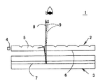
図1はフロントライト2と反射型の液晶表示パネル3とからなる反射型液晶表示装置1の概略断面図である。このようなフロントライト2を用いた反射型液晶表示装置1では、フロントライト2の光出射面6から出射した光は、大きく次の二つに分けられる。その一つは、図1で実線の矢印で示すように、冷陰極線管のような線状の光源4から出た光が導光板5内を伝搬し、その光出射面6からほぼ垂直に出射された後、液晶表示パネル3のガラス基板や液晶層を通過し、反射面7で反射されて元の方向へ戻り、液晶表示パネル3やフロントライト2を通過して観察者側へ出射される画像光8である。もう一方は、図1に破線の矢印で示すように、フロントライト2の光出射面6や液晶表示パネル3のガラス基板表面などで反射することにより、観察者側へ出射されるノイズ光9である。
FIG. 1 is a schematic sectional view of a reflection type liquid
このようなノイズ光9が発生すると、図1に示すように、画像光8とノイズ光9が同じ方向へ出射されるので、液晶表示パネル3により生成された画像に白色光が重なり、画面のコントラストが低下し、視認性が悪くなる。
When such noise light 9 is generated, as shown in FIG. 1, the
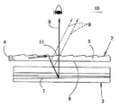
図2に示すものは、上記のような視認性の低下を防止するようにした反射型液晶表示装置10の概略断面図である。この反射型液晶表示装置10においては、導光板5の表面(光出射面6と対向する面)に、断面が鋸刃状をしたパターン11が光源4と平行に(光線に対して垂直に)形成されており、導光板5内を伝搬する光は、パターン11で全反射され、導光板5の光出射面6から斜め方向へ出射されるようになっている。従って、光出射面6から出射する光が光出射面6で反射したり、光出射面6から出射した光が液晶表示パネル3の表面で反射したりしても、そのノイズ光9(正反射光)は観察者側でも斜め方向へ出射されることになり、観察者の目に直接入りにくくなる。そのため画面正面方向におけるノイズ光9が減少し、画面のコントラストが向上することになる。一方、光出射面6から斜め方向に出射された光は、液晶表示パネル3の液晶層を透過した後、適当な傾斜角を持った反射面7によって垂直な方向へ反射され、画面正面方向での画像光8となるので、画面正面方向での明るさも保たれ、視認性が向上する(このような先行技術としては、特許文献1がある)。
FIG. 2 is a schematic cross-sectional view of the reflection type liquid
図2の導光板の構造は、フロントライトの光源として、冷陰極線管、導光ロッド、または複数の点光源からなる線状光源を用いる場合に採用することができる。しかし、いわゆる点光源を用いる場合には、点光源12から出射された光は、図3に平面視で示すように、導光板5内で点光源12を中心として放射状に広がるので、鋸刃状のパターン11で反射されて光出射面6から出射される光の方向が光出射面6内で一定にならない。さらに、一定方向に出射されない光を反射面7で一様に垂直な方向へ反射させようとすると、反射面7の傾斜方向を位置によって異ならせなければならず、反射面7の形状が複雑にならざるを得ない。よって、反射面の設計、製造及びフロントライトとの位置合わせが困難になる。
The structure of the light guide plate of FIG. 2 can be adopted when a cold cathode ray tube, a light guide rod, or a linear light source including a plurality of point light sources is used as the light source of the front light. However, when a so-called point light source is used, the light emitted from the
また、反射面7の形状を、光出射面6から出射される点光源12の光の方向に合わせて製作できたとしても、太陽光のような外光の入射角度は一定方向に揃っているので、点光源12を用いたフロントライトに合わせて傾斜方向を変化させた反射面7によって外光を反射させたのでは、反射面7で反射された光の反射方向がさまざまな方向を向き、外光で使用している時には画面に輝度ムラが生じるという問題が起きる。
Further, even if the shape of the reflecting
本発明は上記のような技術的課題に鑑みてなされたものであり、その目的とするところは、いわゆる点光源を用いたフロントライトにおいて、画像光とノイズ光とが同じ方向へ出射されるのを防止し、また、フロントライトにより照明している場合と外光により照明している場合との照明具合の差を小さくすることにある。 The present invention has been made in view of the above technical problem, and an object of the present invention is to provide a front light using a so-called point light source, in which image light and noise light are emitted in the same direction. Another object of the present invention is to reduce the difference in lighting conditions between when illuminated by a front light and when illuminated by external light.
本発明にかかる第1のフロントライトは、光入射面から入射した光を閉じ込めて伝搬させ、前記光出射面から被照明物に向けて光を出射させる導光板と、導光板の光入射面と対向する位置に配置された点光源とを備えたフロントライトにおいて、前記光出射面から出射する光の光度が最大となる方向が前記光出射面の法線方向に対して斜め方向に傾いており、その光度最大方向が前記光出射面内でほぼ一方向に揃っていることを特徴とする。 A first front light according to the present invention includes: a light guide plate for confining and propagating light incident from a light incident surface and emitting light from the light exit surface toward an object to be illuminated; and a light incident surface of the light guide plate. In a front light including a point light source disposed at an opposing position, a direction in which the luminous intensity of light emitted from the light emitting surface is maximum is inclined in an oblique direction with respect to a normal direction of the light emitting surface. The luminous intensity maximum direction is substantially aligned in one direction in the light emitting surface.
本発明にかかる第1のフロントライトにおいては、出射光の光度が最大となる方向が光出射面の法線方向に対して斜め方向に傾いているので、導光板などで正反射したノイズ光が画像光と同じ方向に出射されることがなく、画像のコントラストを高くすることができる。しかも、その光度が最大となる方向が光出射面内でほぼ一方向に揃っているので、このフロントライトによって照明される反射型表示装置の反射面の構造を簡単にすることができる。 In the first front light according to the present invention, since the direction in which the luminous intensity of the emitted light is maximum is inclined in the oblique direction with respect to the normal direction of the light emitting surface, noise light that is regularly reflected by the light guide plate or the like is generated. The contrast of an image can be increased without being emitted in the same direction as the image light. In addition, since the direction in which the luminous intensity becomes maximum is substantially aligned in one direction in the light emitting surface, the structure of the reflecting surface of the reflective display device illuminated by the front light can be simplified.
本発明の第1のフロントライトは、ある実施態様において、前記導光板の光出射面から出射する光の光度が最大となる方向と前記光出射面に立てた法線とのなす角度が15°以上である。このような実施態様によれば、前記フロントライトを用いている反射型表示装置の画面に外光が映り込むのを防ぐことができる。 In one embodiment, the first front light of the present invention is configured such that an angle between a direction in which the luminous intensity of light emitted from the light exit surface of the light guide plate is maximum and a normal line set on the light exit surface is 15 °. That is all. According to such an embodiment, it is possible to prevent external light from being reflected on the screen of the reflective display device using the front light.
また、本発明の第1のフロントライトは、他の実施態様において、前記導光板の光出射面から出射する光の光度が最大となる方向と前記光出射面に立てた法線とのなす角度が20°以上35°以下である。このような実施態様によれば、このフロントライトを用いた反射型表示装置を手に持って画面を見るとき、外光を用いて画面を照明する場合も、フロントライトを用いて画面を照明する場合も、画面を明るく照らすことができる。 Further, in another embodiment, the first front light of the present invention is an angle formed between a direction in which the luminous intensity of light emitted from the light exit surface of the light guide plate is maximum and a normal line set on the light exit surface. Is not less than 20 ° and not more than 35 °. According to such an embodiment, when viewing the screen while holding the reflective display device using the front light in hand, when illuminating the screen using external light, the screen is illuminated using the front light. Even in this case, the screen can be illuminated brightly.
本発明の第1のフロントライトは、さらに他の実施態様において、前記導光板の光出射面から出射する光の光度が最大となる方向が、前記光出射面から出射された光によって照明される被照明物を観察するときの被照明物の上下方向と前記光出射面の法線とを含む平面に平行である。このような実施態様によれば、フロントライトから出射される光の光度が最大となる方向が、外光を用いる場合の照明方向とほぼ同じ方向を向くので、外光を用いて照明する場合もフロントライトを用いて照明する場合も、同じように画面を明るく照明することができる。 In still another embodiment of the first front light of the present invention, the direction in which the luminous intensity of the light emitted from the light exit surface of the light guide plate is maximized is illuminated by the light emitted from the light exit surface. It is parallel to a plane including the vertical direction of the illuminated object when observing the illuminated object and the normal line of the light emitting surface. According to such an embodiment, since the direction in which the luminous intensity of the light emitted from the front light is maximum is substantially the same as the illumination direction when using external light, the illumination may be performed using external light. Similarly, when illuminating with a front light, the screen can be illuminated brightly.
本発明にかかる第2のフロントライトは、光入射面から入射した光を閉じ込めて伝搬させ、光出射面から出射させる導光板と、導光板の光入射面に対向する位置に配置された点光源とを備えたフロントライトにおいて、前記導光板の光出射面と対向する面には、光を偏向させる傾斜面を含む複数のパターンが設けられており、前記点光源と前記パターンの傾斜面を結ぶ方向の違いに応じて、点光源と前記パターンの傾斜面を結ぶ方向と前記パターンの傾斜面に立てた法線とのなす角度が異なることを特徴とする。 A second front light according to the present invention includes a light guide plate for confining and propagating light incident from a light incident surface and emitting the light from a light exit surface, and a point light source disposed at a position facing the light incident surface of the light guide plate. And a plurality of patterns including an inclined surface that deflects light are provided on a surface of the light guide plate that faces the light exit surface, and connects the point light source and the inclined surface of the pattern. An angle formed by a direction connecting the point light source and the inclined surface of the pattern and a normal line formed on the inclined surface of the pattern differs according to the difference in the direction.
本発明にかかる第2のフロントライトにおいては、点光源とパターンの傾斜面とを結ぶ方向の違いに応じて、光線と傾斜面に立てた法線のなす角度を変化させているので、パターンの方向に応じて反射光の出射方向を広い範囲にわたって制御することができる。 In the second front light according to the present invention, the angle formed between the light ray and the normal formed on the inclined surface is changed in accordance with the difference in the direction connecting the point light source and the inclined surface of the pattern. The emission direction of the reflected light can be controlled over a wide range according to the direction.
本発明にかかる第2のフロントライトは、ある実施態様において、前記導光板の光出射面に垂直な方向から見たとき、前記点光源を中心とする同一円周上にあるパターンの傾斜面に立てた法線が、前記点光源と異なる位置にある1点にほぼ集まっている。このような実施態様によれば、点光源から出射された光をパターンの傾斜面で反射させることにより、一方向に揃えて光出射面から斜め方向へ出射させることができ、画面のコントラストを高めることができる。 The second front light according to the present invention, in one embodiment, when viewed from a direction perpendicular to the light exit surface of the light guide plate, has an inclined surface of a pattern on the same circumference around the point light source. The raised normal lines are substantially gathered at one point at a position different from the point light source. According to such an embodiment, by reflecting the light emitted from the point light source on the inclined surface of the pattern, it is possible to align the light in one direction and emit the light obliquely from the light emission surface, thereby increasing the contrast of the screen. be able to.
本発明にかかる第2のフロントライトは、他の実施態様において、前記点光源を中心とする同一円周上にある前記パターンの長手方向が、前記点光源と前記パターンとを結ぶ直線と、前記点光源を焦点とする楕円との交点における前記楕円の接線方向と一致する。このような実施態様によれば、点光源からの光を光出射面から一方向に揃えて出射させるためのパターンの配置角度を、点光源とパターンを結ぶ方向に応じて容易に設定することができる。 In a second front light according to the present invention, in another embodiment, the longitudinal direction of the pattern on the same circumference around the point light source is a straight line connecting the point light source and the pattern, It coincides with the tangent direction of the ellipse at the intersection with the ellipse whose focal point is the point light source. According to such an embodiment, the arrangement angle of the pattern for aligning and emitting light from the point light source in one direction from the light emitting surface can be easily set according to the direction connecting the point light source and the pattern. it can.
本発明にかかる第2のフロントライトは、さらに他の実施態様において、前記導光板の光出射面に垂直な方向から見たとき、前記パターンは、その長手方向が前記点光源を焦点とする楕円の接線方向と一致するようにして前記楕円上に配置されている。このような実施態様によれば、点光源からの光を光出射面から一方向に揃えて出射させるためのパターンの配置角度を容易に設定することができる。 In a second front light according to the present invention, in still another embodiment, when viewed from a direction perpendicular to the light exit surface of the light guide plate, the pattern has an elliptical shape whose longitudinal direction is the focal point of the point light source. Are arranged on the ellipse so as to coincide with the tangential direction of. According to such an embodiment, it is possible to easily set the arrangement angle of the pattern for emitting the light from the point light source in one direction from the light emitting surface.
本発明にかかる第2のフロントライトは、さらに他の実施態様において、導光板の光出射面に垂直な方向から見たとき、前記点光源を中心とする同一円周上にあるパターンに関しては、各傾斜面の法線がほぼ集まる前記の点と前記点光源を結ぶ方向と、前記点光源と前記パターンを結ぶ方向とのなす角度が大きくなるに従い、前記パターンの傾斜面と前記光出射面に対向する面とのなす角度が大きくなっている。このような実施態様によれば、点光源から出射された光をパターンで反射させることにより、一方向に揃えて斜め方向へ出射させることができ、出射光の指向性を高くでき、画面の輝度を向上させることができる。 The second front light according to the present invention, in still another embodiment, when viewed from a direction perpendicular to the light exit surface of the light guide plate, regarding a pattern on the same circumference centered on the point light source, As the angle between the direction connecting the point light source and the point where the normals of the respective inclined surfaces substantially converge and the direction connecting the point light source and the pattern increases, the inclined surface of the pattern and the light exit surface The angle formed by the facing surface is large. According to such an embodiment, by reflecting the light emitted from the point light source in a pattern, the light emitted from the point light source can be aligned in one direction and emitted in an oblique direction, the directivity of the emitted light can be increased, and the brightness of the screen can be improved. Can be improved.
本発明にかかる第2のフロントライトは、さらに他の実施態様において、前記点光源を中心とする同一円周上にあるパターンの傾斜面に立てた法線が1点にほぼ集まり、前記導光板の光出射面に垂直な方向から見たとき、前記点が前記点光源の位置と一致しないようにしている。このような実施態様によれば、パターンの傾斜面に立てた法線が1点にほぼ集まるようにしているので、点光源から出た光を一方向に揃えたうえで、光出射面から斜め方向へ出射させることができ、出射光の指向性をさらに高くでき、画面の輝度を向上させることができる。 The second front light according to the present invention, in still another embodiment, is characterized in that normals set on an inclined surface of a pattern on the same circumference centering on the point light source are substantially gathered at one point, and the light guide plate is provided. The point does not coincide with the position of the point light source when viewed from a direction perpendicular to the light exit surface of the light source. According to such an embodiment, since the normals set on the inclined surface of the pattern are made to substantially converge at one point, the light emitted from the point light source is aligned in one direction, and then the light is oblique from the light emitting surface. Direction, the directivity of the emitted light can be further increased, and the brightness of the screen can be improved.
本発明にかかる第2のフロントライトは、さらに他の実施態様において、前記光入射面が、前記光出射面から出射された光によって照明される被照明物を観察するときの被照明物の上下方向において、前記導光板の上端部に位置している。このような実施態様によれば、光入射面が被照明物を観察するときの上端部にあるので、光を斜め下方向へ出射しやすくなる。これにより、外光で照明する時の光の入射方向とフロントライトで照明する時の光の入射方向とが揃い、反射型表示装置の反射面で両方の光を垂直方向へ向けて反射させ出射させることができる。 The second front light according to the present invention, in still another embodiment, is characterized in that the light incident surface is located above and below the illuminated object when observing the illuminated object illuminated by light emitted from the light emitting surface. In the direction, it is located at the upper end of the light guide plate. According to such an embodiment, since the light incident surface is at the upper end when observing the illuminated object, light is easily emitted obliquely downward. As a result, the incident direction of light when illuminating with external light is aligned with the incident direction of light when illuminating with the front light, and both lights are reflected in the vertical direction on the reflecting surface of the reflective display device and emitted. Can be done.
本発明にかかる第2のフロントライトは、さらに他の実施態様において、前記点光源が、前記導光板の有効出射領域のコーナー部付近に配置されている。このような実施態様によれば、導光板の有効出射領域のコーナー部付近に点光源を配置しているので、導光板の有効出射領域全面に光を出射させるために必要となる出射光の広がりが狭くて済み、有効出射領域の隅が暗くなる現象を抑えることができる。さらに、画面中央部でノイズ光の出射される方向が画面の上下方向に対して非平行となり、ノイズ光が視認されにくくなる。 In a second front light according to the present invention, in still another embodiment, the point light source is arranged near a corner of an effective emission area of the light guide plate. According to such an embodiment, since the point light source is arranged near the corner of the effective emission area of the light guide plate, the spread of emission light required to emit light over the entire effective emission area of the light guide plate And the phenomenon that the corners of the effective emission area become dark can be suppressed. Furthermore, the direction in which the noise light is emitted at the center of the screen is not parallel to the vertical direction of the screen, and the noise light is less likely to be visually recognized.
本発明にかかる反射型表示装置は、上記各フロントライトと、前記フロントライトの光出射面側に配置され、フロントライトの光出射面から出射された光を反射させる反射面を有する反射型表示パネルとを備えたことを特徴とする。 The reflective display device according to the present invention is a reflective display panel having the front lights described above, and a reflective surface disposed on the light emitting surface side of the front light and reflecting light emitted from the light emitting surface of the front light. And characterized in that:
本発明にかかる反射型表示装置においては、フロントライトの光出射面から、光出射面に立てた法線から傾いた方向へ照明光を出射させ、しかも、光出射面から出射される光の方向を一方向に揃えているので、画面のコントラストを高くすることができ、広い角度から画面を見ることができるようにすることができる。しかも、フロントライトから出射される光の方向が一方向に揃っているので、反射板の構造を簡略にすることができると共に、外光で照明した場合でも画面に輝度ムラが生じにくい。 In the reflection type display device according to the present invention, the illumination light is emitted from the light emission surface of the front light in a direction inclined from a normal set on the light emission surface, and furthermore, the direction of the light emitted from the light emission surface Are aligned in one direction, the contrast of the screen can be increased, and the screen can be viewed from a wide angle. In addition, since the direction of light emitted from the front light is aligned in one direction, the structure of the reflector can be simplified, and luminance unevenness hardly occurs on the screen even when illuminated with external light.
本発明にかかる別の反射型表示装置は、前記のいずれかのフロントライトと、前記フロントライトの光出射面側に配置され、フロントライトの光出射面から出射された光を反射させる反射面を有する反射型表示パネルとを備えた反射型表示装置において、前記反射面は、前記フロントライトに用いられている導光板の光出射面に立てた法線に斜め方向から入射した光を前記光出射面に垂直な方向へ反射させることを特徴とする。 Another reflection type display device according to the present invention includes any one of the above front lights and a reflection surface disposed on a light exit surface side of the front light and reflecting light emitted from the light exit surface of the front light. A reflection type display panel having a reflection type display panel, wherein the reflection surface emits light that is obliquely incident on a normal line set on a light emission surface of a light guide plate used for the front light. The light is reflected in a direction perpendicular to the surface.
本発明にかかる別の反射型表示装置においては、フロントライトの光出射面から、光出射面に立てた法線から傾いた方向へ照明光を出射させ、これを反射面で垂直方向へ反射させており、しかも、光出射面から出射される光の方向を一方向に揃えているので、画面のコントラストをより高くすることができ、広い角度から画面を見ることができるようにすることができる。しかも、フロントライトから出射される光の方向が一方向に揃っているので、反射板の構造を簡略にすることができると共に、外光で照明した場合でも画面に輝度ムラが生じにくい。 In another reflection type display device according to the present invention, the illumination light is emitted from the light emission surface of the front light in a direction inclined from a normal set on the light emission surface, and is reflected vertically by the reflection surface. In addition, since the direction of the light emitted from the light exit surface is aligned in one direction, the contrast of the screen can be increased, and the screen can be viewed from a wide angle. . In addition, since the direction of light emitted from the front light is aligned in one direction, the structure of the reflector can be simplified, and luminance unevenness hardly occurs on the screen even when illuminated with external light.
本発明にかかるフロントライトにおける光制御方法は、光入射面から入射した光を閉じ込めて伝搬させ、光出射面から出射させる導光板と、導光板の光入射面と対向する位置に配置された点光源とを備えたフロントライトにおいて、前記光出射面から出射する光の光度が最大となる方向を光出射面の法線方向に対して斜め方向に傾かせ、その光度最大方向を光出射面内でほぼ一方向に揃えることを特徴とする。 The light control method in the front light according to the present invention includes a light guide plate for confining and propagating light incident from a light incident surface and emitting the light from a light exit surface, and a light guide plate disposed at a position facing the light incident surface of the light guide plate. In a front light provided with a light source, a direction in which the luminous intensity of light emitted from the light emitting surface is maximum is inclined obliquely with respect to a normal direction of the light emitting surface, and the luminous intensity maximum direction is in the light emitting surface. Is characterized in that they are aligned in almost one direction.
本発明にかかるフロントライトにおける光制御方法においては、出射光の光度が最大となる方向が光出射面の法線方向に対して斜め方向に傾いているので、導光板などで正反射したノイズ光が画像光と同じ方向に出射されることがなく、画像のコントラストを高くすることができる。しかも、その光度が最大となる方向が光出射面内でほぼ一方向に揃っているので、このフロントライトによって照明される反射型表示装置の反射面の構造を簡単にすることができる。 In the light control method for the front light according to the present invention, since the direction in which the luminous intensity of the emitted light is maximum is inclined in the oblique direction with respect to the normal direction of the light emitting surface, the noise light specularly reflected by the light guide plate or the like is used. Is not emitted in the same direction as the image light, and the contrast of the image can be increased. In addition, since the direction in which the luminous intensity becomes maximum is substantially aligned in one direction in the light emitting surface, the structure of the reflecting surface of the reflective display device illuminated by the front light can be simplified.
なお、以上で説明した本発明の構成要素は、可能な限り任意に組み合わせることができる。 The components of the present invention described above can be combined as arbitrarily as possible.
本発明のフロントライト、反射型表示装置及びフロントライトにおける光制御方法によれば、光源として点光源を用いた場合に、光源から出射され、パターンで反射された後、導光板の光出射面から出射される光を、光出射面に立てた法線の方向に対して傾いた方向へ出射させ、しかも、光出射面から出射される光の方向をほぼ一定方向に揃えることができる。
すなわち、本発明によれば、点光源を用いた場合でも、画像光とノイズ光が同じ方向に出射されないようにすることができ、視認性が向上すると共に輝度ムラを防止することができる。
According to the light control method in the front light, the reflective display device, and the front light of the present invention, when a point light source is used as the light source, the light is emitted from the light source, and after being reflected by the pattern, from the light emission surface of the light guide plate. The emitted light can be emitted in a direction inclined with respect to the direction of the normal line on the light emitting surface, and the direction of the light emitted from the light emitting surface can be made substantially uniform.
That is, according to the present invention, even when a point light source is used, it is possible to prevent image light and noise light from being emitted in the same direction, thereby improving visibility and preventing luminance unevenness.
以下、本発明の実施例を図面に従って詳細に説明する。 Hereinafter, embodiments of the present invention will be described in detail with reference to the drawings.
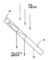
図4は反射型の液晶表示パネル23の前面に本発明の実施例1によるフロントライト22を配置した反射型液晶表示装置21の概略断面図である。また、図5はこのフロントライト22の一部破断した概略斜視図、図6はその平面図である。
FIG. 4 is a schematic sectional view of a reflection type liquid
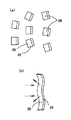
フロントライト22は、発光ダイオード等の発光素子を封止したいわゆる点光源24と、ポリカーボネイト樹脂やアクリル樹脂、メタクリル樹脂等の透明な樹脂によって射出成形等の方法で成形された導光板25とから構成されている。点光源24は、導光板25の有効出射領域25a(図10参照)の外側におけるコーナー部に配置されており、導光板25の上面には点光源24から出射されて導光板25内部を伝搬する光を全反射させるための偏向パターン26が複数形成されている。点光源24は、図5及び図6では導光板25の内部に設けられているが、導光板25のコーナー部の近傍で導光板25の外部に配置されていてもよい。導光板25の上面に設けられている個々の偏向パターン26は、V溝状に凹設されたものであり、図6に示すように、点光源24を中心としてほぼ同心円上に配列されている。
The
また、導光板25の光出射面28から出射される光の強度分布を光出射面全体で均一化するため、偏向パターン26は、点光源24の近傍ではパターン面密度が小さくなっており、点光源24から離れるに従ってパターン面密度が次第に大きくなっている。
In addition, in order to make the intensity distribution of light emitted from the
図4に示す反射型の液晶表示パネル23は、TFT電極を形成された裏面基板31と透明電極を形成されたガラス基板32との間に液晶材料33を封止したものであり、裏面基板31の上には反射面34が形成されている。図7に示すように、裏面基板31の上には絶縁材料層35が形成され、絶縁材料層35には同一形状をした複数の傾斜パターン35aが配列されており、絶縁材料層35の表面にアルミ等の金属蒸着膜を成膜することによって反射面34が形成されている。また、図示しないが、ガラス基板32の上には、偏光板などが設けられる。
The reflective liquid
しかして、このフロントライト22の点光源24を点灯させると、図8(a)及び図5に示すように、点光源24から出射され導光板25内に入射した光(矢印で示す。以下、同様)は、導光板25内に閉じ込められて導光板25の表面27と光出射面28(裏面)との間で全反射を繰り返しながら点光源24から遠ざかる方向へ伝搬すると共に導光板25の全体に広がっていく。この光が偏向パターン26の傾斜面29で全反射されると、導光板25の光出射面28へ向けて進み、光出射面28から液晶表示パネル23へ向けて出射され、液晶表示パネル23を照明する。本発明のフロントライト22では、光出射面28から出射される光は、光出射面28の法線方向に対して斜めに傾斜しており、出射位置にかかわりなく同一方向に傾斜している。
When the point
また、点光源24が点灯されておらず、太陽光などの外光によって液晶表示パネル23が照明される場合には、図8(b)に示すように、導光板25の表面27から入射した外光が導光板25を透過して光出射面28から出射され、液晶表示パネル23を照明する。
When the point
点光源24からの光が、導光板25の光出射面28から斜めに出射されると、図4に示すように、出射された光は液晶表示パネル23のガラス基板32及び液晶材料33を透過して反射面34で反射される。反射面34は、光出射面28から出射された光の入射する方向で下りとなるように傾斜しているので、図7に示すようにフロントライト22から斜めに入射した光は、反射面34によってほぼ垂直方向に向けて反射される。反射面34で反射された画像光は液晶材料33、ガラス基板32、導光板25等をほぼ垂直に透過して反射型液晶表示装置21の画面正面側へ出射され、画面正面方向での輝度を上げることができる。
When the light from the point
このような構造を有する反射型液晶表示装置21は、以下に説明するような特徴を有している。フロントライト22の光出射面28から出射される光が、光出射面28に立てた法線方向から斜めに傾いており、この傾いて入射した光を反射面34でほぼ垂直な方向に反射させて画像光をほぼ画面正面側へ向けて出射させているので、光出射面28から斜めに出射される光が光出射面28やガラス基板32の表面で反射されても、これらのノイズ光は図4に破線矢印で示すように視野角外の斜め方向へ出射されることになり、画像光とノイズ光が重なり合うことがなくコントラストの高い表示画面が得られる。
The reflective liquid
また、光出射面28から斜めに出射される光は、図5に示しているように、同じ方向に揃っているので、反射面34は一定の方向に傾かせておくだけでよく、反射面34の構造が複雑になることがない。さらに、導光板25の光出射面28から出射される点光源24の光は、外光と同じように一方向に揃っており、反射面34の各傾斜パターン35aが一定方向に傾斜しているので、一定方向に揃った外光が入射して反射面34で反射しても、反射光の方向も一定方向を向くことになり、輝度ムラが生じにくく、画面を明るくすることができる。さらに、反射面34の傾斜は複数の傾斜パターン35aの集合によって形成されているので、液晶表示パネル23の厚みが薄くなる(1つの傾斜した反射面であると、液晶表示パネル23の厚みが大きくなる。)。しかも、各傾斜パターン35aが凹面状に湾曲しているので、反射光がわずかに拡散し、反射面34に外光や景色が映り込むのを防止することができる。
In addition, since the light emitted obliquely from the
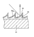
図9は、導光板25内から偏向パターン26の傾斜面29に対して全反射の臨界角よりも小さな入射角(傾斜面29に立てた法線を基準とする入射角)で光が入射した場合を説明している。傾斜面29に入射した光は、傾斜面29を透過して導光板25の表面27から斜め方向へ出射される。また、その一部は傾斜面29から出射した後、傾斜面29の後方の捕捉面30に入射して再び導光板25内に戻り、再利用される。
FIG. 9 shows that light is incident from inside the
フロントライト(図示せず)に冷陰極線管等の線状光源を用いている場合には、図9のように傾斜面29から直接に光が漏れると、漏れた光の方向が導光板25全体で一方向に揃うので、ある角度から画面を見た場合には画面が真っ白になり、もはや画面を視認できなくなる。
When a linear light source such as a cold cathode ray tube is used as a front light (not shown), if light leaks directly from the
これに対し、点光源24を用いたフロントライト22では、図10に示すように、導光板25内を伝搬する光は、点光源24を中心として放射状に広がっているので、偏向パターン26の傾斜面29から直接漏れたノイズ光も線状光源を用いた場合のように一方向に揃うことはなく、点光源24を中心とした半径方向に出射する。そのため、ノイズ光の出射方向が位置によって異なり、線状光源を用いている場合のように画面が真っ白になりにくく、広い視野角で画面を視認することができる。
On the other hand, in the
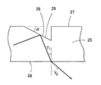
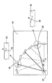
次に、点光源24を中心として同心円状に配列された偏向パターン26によって点光源24からの光を反射させ、偏向パターン26で反射された光を一定方向に揃えて光出射面28から出射させるための構造を説明する。光出射面28からの出射光の方向を一定方向に揃えるためには、点光源24から見た偏向パターン26の方向に応じて、偏向パターン26に入射する光線と偏向パターン26の傾斜面29に立てた法線とのなす角度を変化させればよい。偏向パターン26の傾斜面29に入射する光の角度は、点光源24から見た偏向パターン26の方向(あるいは、偏向パターン26から見た点光源24の方向)に依存しているので、図11(図11では、裏面側を上にして導光板25の内部から偏向パターン26を見ている。)に示すように、点光源24から見た偏向パターン26の位置している方向に応じて、傾斜面29の方向を変化させて入射光線と傾斜面29に立てた法線とのなす角度を変化させれば光の出射方向を制御できる。
Next, the light from the point
詳細には、図12に示すように、点光源24から出射された光が、各偏向パターン26の傾斜面29で反射されて光出射面28から同じ方向へ向けて斜めに出射させるようにするためには、導光板25の光出射面28に垂直な方向から見た時、点光源24を中心として同一円周上に配置されている偏向パターン26の傾斜面29に立てた法線Nがほぼ1点Oで交わるように、各傾斜面29の方向を定めればよい。このように、光出射面28に垂直な方向から見たときに、傾斜面29に立てた法線Nが1点で交わるようにすれば、光出射面28から出射された光の出射方向のばらつきを低減させて、出射方向をほぼ一方向に揃えることができる。
More specifically, as shown in FIG. 12, the light emitted from the point
具体的には、導光板25の光出射面28に垂直な方向から見たとき、法線Nの交点Oと点光源24(点光源の発光領域の中心)を結んだ直線(点光源24を通過し、光出射面28から出射される光線の方向の光出射面28への正射影に平行な直線)と、点光源24(点光源の発光領域の中心)と偏向パターン26を結んだ直線のなす角度をφとし、点光源24と偏向パターン26を結んだ直線と、法線Nとのなす角度をξとし、図13に示すように、傾斜面29で全反射した光が光出射面28へ入射する入射角をγ1とするとき、ξとφが次の(1)式を満足するようにすれば、法線Nが1点Oで交わる。
Specifically, when viewed from a direction perpendicular to the

例えば、光出射面28から出射される光の出射角γ2を20°とする場合には、スネルの法則より、1×sinγ2=n×sinγ1(導光板25の屈折率n=1.53)となるので、上記(1)式のγ1は12.9°となる。
For example, when the emission angle γ 2 of the light emitted from the
また、図13に示すように、偏向パターン26の断面形状は直角三角形、傾斜面29と導光板25の表面27との間の角度はα=50°となっており、この角度は全ての偏向パターン26について一定としている。また、法線Nの交点Oは、偏向パターン26とは同一平面にはなく、図14に示すように、立体的な配置となっている。同一円周上の偏向パターン26の傾斜面29に立てた法線Nは、光出射面28に垂直な方向から見た状態だけでなく、3次元でも1点Oで交差していることが望ましい。なお、上記(1)式の意味するところは、異なる円周上にあっても、点光源24から見て同じ方位に位置する偏向パターン26は、光出射面28に垂直な方向から見たとき、その傾斜面29に立てた法線Nの方向が、点光源24と当該偏向パターン26とを結ぶ方向に対して同じ角度ξだけ傾いているということであるので、上記交点Oは、異なる円周上の偏向パターン26に関しては同じ点にはない。
As shown in FIG. 13, the cross-sectional shape of the
また、偏向パターン26の配置方向は、図15に示すように、点光源24を中心とする同一円周C上にある各偏向パターン26の長手方向が、点光源24と各偏向パターン26とを結ぶ直線と、点光源24を一方の焦点とする楕円Eとの交点における楕円Eの接線方向と一致するようにしても、同様の効果が得られる。
As shown in FIG. 15, the direction in which the
具体的には、図16に示すように、点光源24を一方の焦点とし、かつ、点光源24を中心とする円周Cに長軸方向で内接する楕円Eを考え、点光源24と任意の偏向パターン26とを結ぶ直線を引き、この直線と楕円Eとの交点における楕円Eの接線方向を求め、前記偏向パターン26の長手方向が当該接線方向と平行となるように偏向パターン26の方向を決めることによっても、導光板25の光出射面28から出射される光の方向を揃えることができる。
Specifically, as shown in FIG. 16, an ellipse E having the point
点光源24を中心とする円周C上にある各偏向パターン26の配置方向を決める方法を図16に従ってさらに詳しく説明する。点光源24を中心とする半径rの円周C上にある偏向パターン26を考えると、楕円Eは点光源24を一方の焦点Aとし、かつ、円周Cに内接するから、楕円Eの長径をa、短径をb、焦点A、B間の距離を2pとすると、これらのパラメータと円周Cの半径rとの間には、次のような関係がある。
r=a+p …(2)
p2=a2−b2 …(3)
ここで、導光板25の屈折率をn、空気中の屈折率をn1、導光板25からの光の出射角度をγ2(図13参照)とすると、楕円Eの楕円率が次の(4)式を満たすようにする。例えば、出射角度γ2=20°、屈折率n1=1、n=1.53とすると、この楕円率は、0.97469となる。
A method of determining the arrangement direction of each
r = a + p (2)
p 2 = a 2 −b 2 (3)
Here, assuming that the refractive index of the
上記(2)式、(3)式、(4)式によれば、円周Cの半径rをパラメータとして楕円Eの長径a、短径b、焦点間の距離2pの値を決めることができるので、楕円Eが決まる。
なお、図16は導光板25に垂直な方向から見た説明図であって、u軸方向は、点光源24を通過し、光出射面28から出射される光線の方向の光出射面28への正射影に平行な方向を表しており、v軸方向はu軸方向に垂直な方向を表している。
According to the above equations (2), (3), and (4), the value of the major axis a, the minor axis b, and the distance 2p between the focal points can be determined using the radius r of the circumference C as a parameter. Therefore, the ellipse E is determined.
FIG. 16 is an explanatory diagram viewed from a direction perpendicular to the
こうして偏向パターン26が配置される円周Cに対して楕円Eが決定すると、点光源24と偏向パターン26とを結ぶ直線と楕円Eとの交点における楕円Eの接線と平行な方向となるように偏向パターン26の長手方向を決める。このようにして円周C上の偏向パターン26の方向を決めると、導光板25に垂直な方向から見た場合、円周C上の各偏向パターン26の傾斜面に垂直な法線Nは、点光源24から
L=p(1+p/a)=k・n1・sinγ2
の位置で1点に交わる。但し、kは任意の比例定数である。
When the ellipse E is determined with respect to the circumference C on which the
Intersects one point at the position. Here, k is an arbitrary proportional constant.
また、図16から明らかなように、図16に実線で示す偏向パターン26のように上記(4)式を満たす楕円E上に偏向パターン26を配置すれば、点光源24からの光を導光板25の光出射面28から一方向に斜め出射させることができ、偏向パターン26の配置の設計が容易になる。ただし、円周上に配置する場合と違って、楕円上に配置する場合は、各楕円間の距離が導光板25内の位置によって異なる(例えば、v軸方向では、u軸方向よりも楕円間の間隔が狭くなる。)ため、パターン密度にばらつきが生じる。パターン密度を一定にするためには、位置によってパターンの長手方向の長さを調節すればよい。
また、偏向パターン26は、点光源24からの光が偏向パターン26の傾斜面ではなく側面で反射されてノイズ光となるのを防止するために、側面が点光源24からの光線に対して平行になっているか、または、後方で内側へ引っ込むように傾斜していることが望ましい。
Further, as is apparent from FIG. 16, if the
Further, the
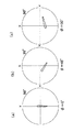
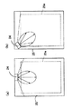
図17(a)(b)(c)はそれぞれ、上記のような構造のフロントライト22を用いて、図18に示すように点光源24を中心としてφ=0°、45°、90°の各方向に位置する箇所P1、P2、P3における出射光の光度分布をシミュレーションした結果を示しており、いずれも光度の最大値の半値以上の光度を持つ領域をプロットしている。また、図17(a)(b)(c)の横軸は図18のx軸方向(前記v方向)を示し、縦軸は図18のy軸方向(前記−u方向)を示しており、光出射面28に立てた法線の方向から90°傾いた方位までを表している。図17(a)(b)(c)から分かるように、いずれの場合も、光度が半値以上の領域は点光源24と当該箇所とを結ぶ方向に長い領域となっているが、どの場合もy軸上に位置しており、出射方向が特定方向を向いてほぼ揃っている。反射型の液晶表示パネル23は、反射面34に拡散特性を有しているので、フロントライト22の各位置からの出射光の光度分布の半値以上の領域が特定の方向を含んでいれば、画面に輝度ムラが生じず、視認性が保たれる。また、この特定の方向は光出射面28に垂直な方向とは異なっているので、フロントライト22の光出射面28や液晶表示パネル23の表面での反射光が画面正面方向に出射せず、コントラストが高くなる。
FIGS. 17 (a), (b), and (c) show the cases where φ = 0 °, 45 °, and 90 ° around the point
次に、実際の使用形態の上から考えてみる。反射型液晶表示装置21は、携帯電話などのディスプレイとして使用されるので、上下方向に立てた状態で、あるいは斜めに立てた姿勢で使用又は観察されることが多い。このような反射型液晶表示装置21においては、フロントライト22の光出射面28から出射される光の出射方向は上下方向に傾いていることが望ましい。特に、下方へ向けて傾いていることが望ましい。そのためには、点光源24は、使用状態において導光板25の上端部(画像光が透過する領域となる有効出射領域25aの外側)に配置してあればよい。点光源24を導光板25の上端部に配置すれば、図19に示すように、フロントライト22からの出射光を斜め下方向へ出射させ易くなる。すなわち、偏向パターン26の傾斜面29に立てた法線と傾斜面29に入射する光線とのなす角度が大きくなり、光を傾斜面29で全反射させて下方へ出射させることができるようになる。
Next, let us consider the actual usage form. Since the reflection type liquid
こうして、フロントライト22から斜め下方向へ光を出射させることにより、外光の入射方向(及び出射方向)とフロントライト22から出射される光の方向が揃い、液晶表示パネル23の反射面34で反射させて外光とフロントライト22からの光との両方の光を垂直方向(反射型液晶表示装置21の正面方向)に出射できるようになる。その結果、フロントライト22で液晶表示パネル23を照明しているときと、外光で液晶表示パネル23を照明しているときとで、同じような照明具合を実現でき、画面を見やすくできる。加えて、有効出射領域25aの全面に光を行き渡らせて輝度ムラを抑えるためには、有効出射領域25aの短辺側に点光源24が配置されることが望ましい。
In this manner, the light is emitted obliquely downward from the front light 22 so that the incident direction (and the emission direction) of the external light and the direction of the light emitted from the
次に、導光板25の光出射面28から出射される光の角度について考える。太陽光や照明光などの外光は通常反射型液晶表示装置21よりも十分高い位置にあるので、外光が導光板25に入射する角度は、反射型液晶表示装置21の角度(使用形態)によって決まる。ここで携帯電話等の小型の携帯機器を手に持って画面正面から観察する場合、液晶画面の傾きが15°よりも小さいと、図20に示すようにフロントライト22の表面などで反射したノイズ光が画像光と一緒に観察され、画像のコントラストが低下して見にくくなる。すなわち、ほぼ真上から入射する外光に対して液晶画面を水平方向から15°以上傾けると、液晶画面に外光が映り込まない。したがって、フロントライト22の光出射面28からの出射角を外光と同じ15°より大きくすれば、外光が映りこまない角度で画面を見ることができる。よって、光出射面28から出射される光の出射方向を、光出射面28に立てた法線に対して15°以上の角度傾ければよい。
Next, the angle of light emitted from the
また、携帯機器を手に持つことを考えると、普通に持てば、その液晶画面は水平方向に対して20°〜35°の範囲で傾き、外光の入射角は20°〜35°となる。従って、光出射面28からの出射角を、光出射面28に立てた法線に対して外光入射角と同じ20°以上35°以下の角度で傾ければよい。
Considering that the portable device is held in hand, if the user holds the device normally, the liquid crystal screen is tilted in the range of 20 ° to 35 ° with respect to the horizontal direction, and the incident angle of external light is 20 ° to 35 °. . Therefore, the emission angle from the
なお、上記実施形態では、偏向パターン26の断面形状は直角三角形となっていたが、偏向パターン26は他の断面形状を有するものでも良い。すなわち、断面が直角三角形の偏向パターン26では、偏向パターン26の傾斜面29で反射せずに透過した光がそのまま観察者方向へ出射されず、捕捉面30から導光板25内に再入射しやすくなる(図9参照)。これに対し、光を反射するための傾斜面を有しているものであれば、他の断面形状を有する偏向パターン26でも差し支えない。また、図21に示すように、出射光に拡散性を持たせるために傾斜面29が曲面を含んでいても良い。
In the above embodiment, the cross-sectional shape of the
また、点光源24は、図22(a)に示すように、導光板25上端部(画像光が透過する領域となる有効出射領域25aの外側)の中央部に配置しても差し支えない。しかし、点光源24を中央部に配置すると、図22(a)に示すように、点光源24から出射される光をほぼ180°の広い指向角を持たせないと、有効出射領域25a(画面)の隅に暗部が生じる恐れがある。これに対し、点光源24を導光板25のコーナー部に配置すれば、図22(b)に示すように、点光源24から出射される光の指向角を90°程度まで狭くすることができ、有効出射領域25aに暗部が生じにくくなる。また、点光源24をコーナー部分に配置すれば、画面中央部において、導光板25の表面27から観察者方向へ直接出射するノイズ光の出射方向が、画面上下方向に対して斜め方向となり、観察者にノイズ光が視認されにくくなる。
Further, as shown in FIG. 22A, the point
図23は本発明の実施例2を説明する図である。実施例1では、偏向パターン26に設けられた傾斜面29の傾斜角度αはいずれも同じ角度(50°)となっていたが、この実施例2では、位置によって傾斜面29の傾斜角度αを変化させている。すなわち、図23に示すように、光出射面28に垂直な方向から見たとき、点光源24を中心とする同一円周上にある偏向パターン26については、各傾斜面29に立てた法線がほぼ交わる点Oと点光源24を結ぶ方向と、点光源24と偏向パターン26を結ぶ方向とのなす角度φが大きくなるに従い、偏向パターン26の傾斜角度α(傾斜面29と導光板25の表面27とのなす角度)が次第に大きくなるようにしている。
FIG. 23 is a view for explaining
具体的に言うと、点光源24を中心として同一円周上にある偏向パターン26の傾斜面29に立てた法線が空間のほぼ同一の位置Oで交わるように(図14参照)傾斜角αを設定しており、次のように決められる。導光板25の光出射面28に垂直な方向から見たとき、各傾斜面29に立てた法線がほぼ交わる点Oと点光源24を結ぶ方向と、点光源24と偏向パターン26を結ぶ方向とのなす角度をφとし、傾斜面29で全反射した光が光出射面28へ入射する入射角をγ1(前記のように、例えば12.9°となる。)とする(図13参照)とき、傾斜面29の傾斜角αは、次の(5)式を満足するように決められる。もちろん、偏向パターン26の配置は、前記(1)式も満たすものとする。
More specifically, the inclination angle α is set so that the normals to the
図24(a)(b)(c)はそれぞれ、傾斜角αを変化させたフロントライト22を用いて、図18に示すように点光源24を中心としてφ=0°、45°、90°の各方向に位置する箇所P1、P2、P3における出射光の光度分布をシミュレーションした結果を示しており、いずれも光度が最大となる領域をプロットしている。また、図24(a)(b)(c)の横軸は図18のx軸方向を示し、縦軸は図18のy軸方向を示しており、光出射面28に立てた法線の方向から90°傾いた方位までを表している。実施例2では、光出射面28からの出射光の光度が最大となる方向は、光出射面28の法線方向に対して19〜26°傾斜しており、光出射面28に垂直な方向から見たとき上下方向(y軸方向)
に対して±16°以内の半値幅を持っていた。
24 (a), (b), and (c) show the case where the front light 22 with the changed inclination angle α is used, and φ = 0 °, 45 °, and 90 ° around the point
Had a half width within ± 16 °.
図25は本発明にかかるフロントライト22を用いた別な反射型液晶表示装置41の概略断面図である。このフロントライト22は、実施例1で説明したものとほぼ同じものであるが、点光源24は導光板25の外側に配置されている。
FIG. 25 is a schematic sectional view of another reflective liquid
液晶表示パネル23にあっては、ガラス基板32と裏面基板31との間に液晶材料33を封止してあり、ガラス基板32の上には、1/4波長板42や偏光板43が設けられている。ただし、1/4波長板42は必ずしも必要なものではなく、1/4波長板42を使用しなくてもよい。裏面基板31とガラス基板32のうち一方には、画素をオン、オフするためのTFT電極が設けられており、他方には透明電極が設けられている。また、カラーの反射型液晶表示装置41の場合には、液晶材料33の上又は下にカラーフィルタが設置される。
In the liquid
さらに、裏面基板31の上面には、図26に示すように、絶縁材料層35によって表面が凸曲した傾斜パターン35aが一定ピッチ毎に配列されており、絶縁材料層35の上にアルミ等の金属材料を蒸着させて反射面34が形成されている。
Further, on the upper surface of the
しかして、この反射型液晶表示装置41にあっても、図25に示すように、導光板25内を伝搬する光は、偏向パターン26で全反射されることによって導光板25の光出射面28に対して22°傾いた方向へ出射され、光出射面28から出射された光は反射面34の傾斜したパターンで反射されて垂直上方へ反射され、反射型液晶表示装置41の正面へ出射される。このとき、反射面34のパターンが湾曲しているので、反射面34で反射された光はわずかに散乱され、外光や背景の映り込みが防止される。
Thus, even in the reflection type liquid
また、導光板25の光出射面28やガラス基板32で正反射されたノイズ光は、図25に破線で示すように斜め方向へ出射されるので、正面に出射された画像光と重なり合わず、画像のコントラストを向上させることができる。
In addition, the noise light that is specularly reflected by the
図27(a)(b)は、上記のような反射型液晶表示装置41を用いて反射型液晶表示装置41の正面から出射される光の輝度分布を測定した結果を示す図である。この図の横軸は、反射型液晶表示装置41の画面に垂直に立てた法線の方向を0°とし、その法線方向からの傾きを表している。この測定結果からも、反射面34で反射された光が垂直方向(正面)へ向けて反射されていることが分かる。
FIGS. 27A and 27B are diagrams showing the results of measuring the luminance distribution of light emitted from the front of the reflective liquid
なお、この実施例では、傾斜したパターンからなる反射面34を用いたが、必ずしも斜め方向から入射した光を反射面で垂直方向へ反射させる必要はなく、通常の拡散性を有する反射面であってもよい。その場合には、フロントライト22の光出射面28から出射される光の出射角を、反射面34の拡散角に比べて小さな角度で斜め方向へ出射させることが好ましい。
In this embodiment, the reflecting
また、フロントライト22の光出射面28を出射した光は、液晶材料33を通過した後、反射面34によって反射されるが、この反射面34は拡散性を持つので、フロントライト22からの出射光が理想的な方向から多少ずれていたり、多少ばらついていたりしても、画面の視認性に大きな影響はない。例えば、フロントライト22の出射光の指向性が比較的低い場合には、各出射位置でのフロントライト22の出射光の光度が半値以上である方向が特定の方向を含んでいればよく、その特定の方向が光出射面28に対して垂直方向でなければ画面正面方向へ出射するノイズ光を低減できる。また、反射面34の拡散性は、入射した平行光を±30°方向に拡散させるので、フロントライト22の出射光の指向性が高い場合には、各位置でのフロントライト22の出射光の光度が最大となる方向が特定方向を中心に30°の範囲でばらつきを持ってもよい。
The light emitted from the
これまで説明したところでは、同一円周上にある偏向パターン26の傾斜面29に立てた法線を延長した直線がほぼ同一の位置Oで交わるとしたが、この偏向パターン26の傾斜面29に立てた法線方向の許容範囲を考える。傾斜面29の法線方向が同一の点Oで交わる方向であることが理想的であるが、所定の範囲内で法線方向が交点Oからずれていても問題はない。
In the description so far, it has been assumed that the straight line extending from the
すなわち、反射型液晶表示装置の反射面34が±30°の方向に光を拡散させる場合には、フロントライト22からの出射光の光度が最大となる方向は、特定方向を中心に30°の範囲でばらつきを持っていてもよい。このとき、導光板25を形成する材料の屈折率を1.5、出射方向を20°とすると、スネルの法則から偏向パターン26の傾斜面29で反射した光は導光板25内において20°程度の範囲で理想的な方向からずれても良いこととなる。これより傾斜面29の法線方向が理想的な方向から10°以内の範囲でずれていてもよいことがわかる(傾斜面29の角度が1°ずれると、反射光の反射方向は2°ずれるからである。)。
That is, when the
また、傾斜面29の法線方向にばらつきを持たせ、フロントライト22の出射光に拡散性を持たせてもよい。この場合、点光源24を中心として同一円周上にある導光板25の表面において、ある領域内での傾斜面29の法線方向の平均の方向が、その他の領域における傾斜面29の法線方向の平均の方向とほぼ同一の点で交わればよく、図28(a)に示すように、偏向パターン26の向きにばらつきを持ち、ある領域内における傾斜面29の法線の方向が、法線方向の平均方向を中心にばらついていてもよい。さらに、図28(b)に示すように、偏向パターン26の傾斜面29を蛇行状に湾曲させることにより拡散性を持たせることもできる。傾斜面29の法線方向にばらつきを持たせる場合には、所定領域内の傾斜面29の法線の平均方向を中心に30°以内の範囲が望ましい。
Further, the light emitted from the
(点光源について)
これまで点光源という用語を用いたが、本発明でいう(特に、特許請求の範囲における用語としての)点光源とは、文字通りの点光源よりも広い概念で用いている。すなわち、導光板の光出射面に垂直な方向から見たとき、光出射面の各位置において出射光の進行方向が揃っていることが望ましい。光源の発光領域が点であれば、光の進行方向を揃えることができるが、実際には発光領域は有限の大きさを持つ。導光板の有効出射領域のうち50%以上の領域において、その領域内の任意の点と光源の発光領域の両端とを結んだ直線のなす角度が10°以下となれば、光を精度良く制御することができ、そのような大きさの光源は点光源として扱うことができる。また、導光板の有効出射領域の50%以上の領域において、その領域内の任意の点と光源の発光領域の両端とを結んだ直線のなす角度が25°以下であれば、実質的に問題なく光を制御し、出射させることができる。
(About point light source)
The term "point light source" has been used so far, but the term "point light source" (especially as a term in the claims) used in the present invention has a broader concept than a literal point light source. That is, when viewed from a direction perpendicular to the light emitting surface of the light guide plate, it is desirable that the traveling directions of the emitted light are uniform at each position on the light emitting surface. If the light emitting area of the light source is a point, the light traveling direction can be made uniform, but in practice, the light emitting area has a finite size. In an area of 50% or more of the effective emission area of the light guide plate, if the angle formed by a straight line connecting an arbitrary point in the area and both ends of the light emitting area of the light source is 10 ° or less, light is accurately controlled. Light sources of such a size can be treated as point light sources. Further, in an area of 50% or more of the effective emission area of the light guide plate, if the angle between a straight line connecting any point in the area and both ends of the light emitting area of the light source is 25 ° or less, there is a substantial problem. The light can be controlled and emitted without the need.
従って、本発明にいう点光源とは、常識的な意味における点光源のほか、上記のような条件を満たすものが含まれる。すなわち、導光板との関係において、導光板の有効出射領域の50%以上の領域において、その領域内の任意の点と光源の発光領域の両端とを結んだ直線のなす角度が25°以下であれば、そこに用いられている光源は、本発明にかかる点光源である。 Therefore, the point light source in the present invention includes not only a point light source in a common sense but also a light source satisfying the above conditions. That is, in relation to the light guide plate, in an area of 50% or more of the effective emission area of the light guide plate, the angle formed by a straight line connecting any point in the area and both ends of the light emitting area of the light source is 25 ° or less. If there is, the light source used therein is the point light source according to the present invention.
また、点光源の発光点は1つである必要はなく、近接して配置されていて局在化されていれば複数の発光点を有していてもよい。 Further, the point light source need not have one light emitting point, and may have a plurality of light emitting points as long as they are arranged close to each other and are localized.
また、反射型表示パネルの例として、上記実施例では液晶表示パネルで説明したが、これは液晶を用いたものには限らない。 In addition, as an example of the reflective display panel, the liquid crystal display panel has been described in the above embodiment, but the present invention is not limited to a liquid crystal display panel.
(アプリケーション)
図29は本発明にかかる反射型液晶表示装置21(あるいは、反射型液晶表示装置41でもよい。)を組み込まれた携帯電話51を示している。この携帯電話51は、テンキー等を備えたダイアル部52の上に反射型液晶表示装置21が組み込まれており、上面にアンテナ53が設けられている。
(application)
FIG. 29 shows a
図30は本発明にかかる反射型液晶表示装置21(あるいは、反射型液晶表示装置41でもよい。)を組み込まれたPDA等の携帯情報端末54を示している。この携帯情報端末54は、反射型液晶表示装置21の横にペン入力などの入力部55が設けられており、上端部には蓋56が枢着されている。
FIG. 30 shows a
このように携帯電話51や携帯情報端末54等に本発明の反射型液晶表示装置21を用いることにより、コントラストが良好で視認性の良好な表示部を持たせることができる。
As described above, by using the reflective liquid
本発明のフロントライトは、上記アプリケーションからも明らかなように反射型表示装置、特に反射型液晶表示装置のフロントライトとして用いることができるものであり、さらに、携帯情報端末や携帯電話等の携帯機器に限らず、種々の機器の表示部に用いることができるものである。 As apparent from the above application, the front light of the present invention can be used as a front light of a reflective display device, particularly a reflective liquid crystal display device, and furthermore, a portable device such as a portable information terminal or a mobile phone. The present invention is not limited to this, and can be used for display units of various devices.
21 反射型液晶表示装置
22 フロントライト
23 液晶表示パネル
24 点光源
25 導光板
25a 有効出射領域
26 偏向パターン
28 光出射面
29 傾斜面
33 液晶材料
34 反射面
DESCRIPTION OF
Claims (15)
前記光出射面から出射する光の光度が最大となる方向が前記光出射面の法線方向に対して斜め方向に傾いており、その光度最大方向が前記光出射面内でほぼ一方向に揃っていることを特徴とするフロントライト。 In a front light including a light guide plate for confining and propagating light incident from a light incident surface and emitting light from a light exit surface, and a point light source arranged at a position facing the light incident surface of the light guide plate,
The direction in which the luminous intensity of the light emitted from the light exit surface is maximum is inclined in an oblique direction with respect to the normal direction of the light exit surface, and the direction of the maximum luminous intensity is substantially aligned in one direction in the light exit surface. A front light characterized by being.
前記導光板の光出射面と対向する面には、光を偏向させる傾斜面を含む複数のパターンが設けられており、前記点光源と前記パターンの傾斜面を結ぶ方向の違いに応じて、点光源と前記パターンの傾斜面を結ぶ方向と前記パターンの傾斜面に立てた法線とのなす角度が異なることを特徴とするフロントライト。 In a front light including a light guide plate for confining and propagating light incident from a light incident surface and emitting the light from a light exit surface, and a point light source disposed at a position facing the light incident surface of the light guide plate,
A plurality of patterns including an inclined surface that deflects light are provided on a surface of the light guide plate that faces the light emitting surface, and a point is provided according to a difference in a direction connecting the point light source and the inclined surface of the pattern. A front light, wherein an angle between a direction connecting a light source and the inclined surface of the pattern and a normal line formed on the inclined surface of the pattern is different.
前記反射面は、前記フロントライトに用いられている導光板の光出射面に立てた法線に斜め方向から入射した光を前記光出射面に垂直な方向へ反射させることを特徴とする反射型表示装置。 11. A front light according to claim 1, and a reflective display panel disposed on a light emitting surface side of the front light and having a reflective surface that reflects light emitted from the light emitting surface. 12. Reflective display device,
The reflection type is characterized in that light incident from a diagonal direction on a normal line formed on a light emission surface of a light guide plate used for the front light is reflected in a direction perpendicular to the light emission surface. Display device.
前記光出射面から出射する光の光度が最大となる方向を光出射面の法線方向に対して斜め方向に傾かせ、その光度最大方向を光出射面内でほぼ一方向に揃えることを特徴とするフロントライトにおける光制御方法。 In a front light including a light guide plate for confining and propagating light incident from a light incident surface and emitting light from a light exit surface, and a point light source arranged at a position facing the light incident surface of the light guide plate,
The direction in which the luminous intensity of the light emitted from the light emitting surface is maximum is inclined in an oblique direction with respect to the normal direction of the light emitting surface, and the maximum luminous intensity direction is substantially aligned in one direction in the light emitting surface. Light control method in the front light.
Priority Applications (3)
| Application Number | Priority Date | Filing Date | Title |
|---|---|---|---|
| JP2003347514A JP2004361914A (en) | 2003-05-15 | 2003-10-06 | Front light, reflective display device, and light control method in front light |
| US10/843,213 US7163330B2 (en) | 2003-05-15 | 2004-05-11 | Front light, reflective type of display, and light controlling method |
| CNB2004100381851A CN1321336C (en) | 2003-05-15 | 2004-05-14 | Headlight ,reflective display device and light control method for headlight |
Applications Claiming Priority (2)
| Application Number | Priority Date | Filing Date | Title |
|---|---|---|---|
| JP2003138023 | 2003-05-15 | ||
| JP2003347514A JP2004361914A (en) | 2003-05-15 | 2003-10-06 | Front light, reflective display device, and light control method in front light |
Publications (2)
| Publication Number | Publication Date |
|---|---|
| JP2004361914A true JP2004361914A (en) | 2004-12-24 |
| JP2004361914A5 JP2004361914A5 (en) | 2006-11-02 |
Family
ID=33554368
Family Applications (1)
| Application Number | Title | Priority Date | Filing Date |
|---|---|---|---|
| JP2003347514A Pending JP2004361914A (en) | 2003-05-15 | 2003-10-06 | Front light, reflective display device, and light control method in front light |
Country Status (3)
| Country | Link |
|---|---|
| US (1) | US7163330B2 (en) |
| JP (1) | JP2004361914A (en) |
| CN (1) | CN1321336C (en) |
Cited By (2)
| Publication number | Priority date | Publication date | Assignee | Title |
|---|---|---|---|---|
| JP2006259115A (en) * | 2005-03-16 | 2006-09-28 | Omron Corp | Both-surface display device and surface light emission device |
| JP2006301326A (en) * | 2005-04-21 | 2006-11-02 | Toppan Printing Co Ltd | Light guide plate and liquid crystal display device |
Families Citing this family (65)
| Publication number | Priority date | Publication date | Assignee | Title |
|---|---|---|---|---|
| JP2003150073A (en) * | 2001-08-27 | 2003-05-21 | Omron Corp | Image display unit and front light |
| TWI289708B (en) * | 2002-12-25 | 2007-11-11 | Qualcomm Mems Technologies Inc | Optical interference type color display |
| JP4431952B2 (en) * | 2003-11-10 | 2010-03-17 | オムロン株式会社 | Surface light source device and equipment using the device |
| US7269590B2 (en) * | 2004-01-29 | 2007-09-11 | Yahoo! Inc. | Method and system for customizing views of information associated with a social network user |
| US7342705B2 (en) | 2004-02-03 | 2008-03-11 | Idc, Llc | Spatial light modulator with integrated optical compensation structure |
| US7856449B1 (en) * | 2004-05-12 | 2010-12-21 | Cisco Technology, Inc. | Methods and apparatus for determining social relevance in near constant time |
| US20060132383A1 (en) * | 2004-09-27 | 2006-06-22 | Idc, Llc | System and method for illuminating interferometric modulator display |
| US7813026B2 (en) * | 2004-09-27 | 2010-10-12 | Qualcomm Mems Technologies, Inc. | System and method of reducing color shift in a display |
| TWI274827B (en) * | 2006-03-24 | 2007-03-01 | Wintek Corp | Light guide plate, light deflecting element configuration and surface light source device |
| US8872085B2 (en) | 2006-10-06 | 2014-10-28 | Qualcomm Mems Technologies, Inc. | Display device having front illuminator with turning features |
| EP2366945A1 (en) * | 2006-10-06 | 2011-09-21 | Qualcomm Mems Technologies, Inc. | Optical loss layer integrated in an illumination apparatus of a display |
| US8107155B2 (en) * | 2006-10-06 | 2012-01-31 | Qualcomm Mems Technologies, Inc. | System and method for reducing visual artifacts in displays |
| US20090069034A1 (en) * | 2007-09-10 | 2009-03-12 | Fatdoor, Inc | Neighbor to neighbor relay in a geo-spatial environment |
| US7733439B2 (en) * | 2007-04-30 | 2010-06-08 | Qualcomm Mems Technologies, Inc. | Dual film light guide for illuminating displays |
| CN101382698B (en) * | 2007-09-06 | 2012-01-11 | 富士迈半导体精密工业(上海)有限公司 | Backlight module unit |
| US7949213B2 (en) * | 2007-12-07 | 2011-05-24 | Qualcomm Mems Technologies, Inc. | Light illumination of displays with front light guide and coupling elements |
| US8068710B2 (en) | 2007-12-07 | 2011-11-29 | Qualcomm Mems Technologies, Inc. | Decoupled holographic film and diffuser |
| US20090168459A1 (en) * | 2007-12-27 | 2009-07-02 | Qualcomm Incorporated | Light guide including conjugate film |
| US8721149B2 (en) | 2008-01-30 | 2014-05-13 | Qualcomm Mems Technologies, Inc. | Illumination device having a tapered light guide |
| US8348489B2 (en) * | 2008-01-30 | 2013-01-08 | Qualcomm Mems Technologies, Inc. | Thin illumination system |
| WO2009102731A2 (en) | 2008-02-12 | 2009-08-20 | Qualcomm Mems Technologies, Inc. | Devices and methods for enhancing brightness of displays using angle conversion layers |
| US8654061B2 (en) * | 2008-02-12 | 2014-02-18 | Qualcomm Mems Technologies, Inc. | Integrated front light solution |
| US8049951B2 (en) | 2008-04-15 | 2011-11-01 | Qualcomm Mems Technologies, Inc. | Light with bi-directional propagation |
| JP5451754B2 (en) * | 2008-05-28 | 2014-03-26 | クォルコム・メムズ・テクノロジーズ・インコーポレーテッド | Optical waveguide panel having turning microstructure, method for manufacturing the same, and display device |
| CN102177398B (en) | 2008-10-10 | 2015-01-28 | 高通Mems科技公司 | Distributed illumination system |
| US8351793B2 (en) * | 2008-10-22 | 2013-01-08 | Qualcomm Mems Technologies, Inc. | Free space optical communication with optical film |
| JP5342016B2 (en) * | 2009-01-13 | 2013-11-13 | クォルコム・メムズ・テクノロジーズ・インコーポレーテッド | Large area light panel and screen |
| BRPI0924132A2 (en) | 2009-01-23 | 2016-02-10 | Qualcomm Mems Technologies Inc | lighting device and system and lighting device manufacturing and object movement detection methods through lighting panel |
| KR20120027415A (en) * | 2009-05-29 | 2012-03-21 | 퀄컴 엠이엠스 테크놀로지스, 인크. | Illumination devices for reflective displays |
| WO2010138763A1 (en) * | 2009-05-29 | 2010-12-02 | Qualcomm Mems Technologies, Inc. | Illumination devices and methods of fabrication thereof |
| TWM375632U (en) * | 2009-09-04 | 2010-03-11 | Depo Auto Parts Ind Co Ltd | Vehicle optical device |
| US20110169428A1 (en) * | 2010-01-08 | 2011-07-14 | Qualcomm Mems Technologies, Inc. | Edge bar designs to mitigate edge shadow artifact |
| US20120249797A1 (en) | 2010-02-28 | 2012-10-04 | Osterhout Group, Inc. | Head-worn adaptive display |
| US9223134B2 (en) | 2010-02-28 | 2015-12-29 | Microsoft Technology Licensing, Llc | Optical imperfections in a light transmissive illumination system for see-through near-eye display glasses |
| US9097891B2 (en) | 2010-02-28 | 2015-08-04 | Microsoft Technology Licensing, Llc | See-through near-eye display glasses including an auto-brightness control for the display brightness based on the brightness in the environment |
| US8488246B2 (en) | 2010-02-28 | 2013-07-16 | Osterhout Group, Inc. | See-through near-eye display glasses including a curved polarizing film in the image source, a partially reflective, partially transmitting optical element and an optically flat film |
| US8482859B2 (en) | 2010-02-28 | 2013-07-09 | Osterhout Group, Inc. | See-through near-eye display glasses wherein image light is transmitted to and reflected from an optically flat film |
| US9097890B2 (en) | 2010-02-28 | 2015-08-04 | Microsoft Technology Licensing, Llc | Grating in a light transmissive illumination system for see-through near-eye display glasses |
| WO2011106798A1 (en) * | 2010-02-28 | 2011-09-01 | Osterhout Group, Inc. | Local advertising content on an interactive head-mounted eyepiece |
| US8472120B2 (en) | 2010-02-28 | 2013-06-25 | Osterhout Group, Inc. | See-through near-eye display glasses with a small scale image source |
| US8467133B2 (en) | 2010-02-28 | 2013-06-18 | Osterhout Group, Inc. | See-through display with an optical assembly including a wedge-shaped illumination system |
| US9759917B2 (en) | 2010-02-28 | 2017-09-12 | Microsoft Technology Licensing, Llc | AR glasses with event and sensor triggered AR eyepiece interface to external devices |
| US9285589B2 (en) | 2010-02-28 | 2016-03-15 | Microsoft Technology Licensing, Llc | AR glasses with event and sensor triggered control of AR eyepiece applications |
| US9129295B2 (en) | 2010-02-28 | 2015-09-08 | Microsoft Technology Licensing, Llc | See-through near-eye display glasses with a fast response photochromic film system for quick transition from dark to clear |
| US9091851B2 (en) | 2010-02-28 | 2015-07-28 | Microsoft Technology Licensing, Llc | Light control in head mounted displays |
| US20110214082A1 (en) * | 2010-02-28 | 2011-09-01 | Osterhout Group, Inc. | Projection triggering through an external marker in an augmented reality eyepiece |
| US8477425B2 (en) | 2010-02-28 | 2013-07-02 | Osterhout Group, Inc. | See-through near-eye display glasses including a partially reflective, partially transmitting optical element |
| US9366862B2 (en) | 2010-02-28 | 2016-06-14 | Microsoft Technology Licensing, Llc | System and method for delivering content to a group of see-through near eye display eyepieces |
| US9229227B2 (en) | 2010-02-28 | 2016-01-05 | Microsoft Technology Licensing, Llc | See-through near-eye display glasses with a light transmissive wedge shaped illumination system |
| US9182596B2 (en) | 2010-02-28 | 2015-11-10 | Microsoft Technology Licensing, Llc | See-through near-eye display glasses with the optical assembly including absorptive polarizers or anti-reflective coatings to reduce stray light |
| US10180572B2 (en) | 2010-02-28 | 2019-01-15 | Microsoft Technology Licensing, Llc | AR glasses with event and user action control of external applications |
| US9128281B2 (en) | 2010-09-14 | 2015-09-08 | Microsoft Technology Licensing, Llc | Eyepiece with uniformly illuminated reflective display |
| US9341843B2 (en) | 2010-02-28 | 2016-05-17 | Microsoft Technology Licensing, Llc | See-through near-eye display glasses with a small scale image source |
| US20150309316A1 (en) | 2011-04-06 | 2015-10-29 | Microsoft Technology Licensing, Llc | Ar glasses with predictive control of external device based on event input |
| US9134534B2 (en) | 2010-02-28 | 2015-09-15 | Microsoft Technology Licensing, Llc | See-through near-eye display glasses including a modular image source |
| US8786803B2 (en) * | 2010-05-13 | 2014-07-22 | Samsung Display Co., Ltd. | Backlight assembly and display apparatus having the same |
| US8402647B2 (en) | 2010-08-25 | 2013-03-26 | Qualcomm Mems Technologies Inc. | Methods of manufacturing illumination systems |
| US8902484B2 (en) | 2010-12-15 | 2014-12-02 | Qualcomm Mems Technologies, Inc. | Holographic brightness enhancement film |
| KR101761886B1 (en) | 2011-01-03 | 2017-07-27 | 삼성디스플레이 주식회사 | Display apparatus and method of assembling the same |
| CN103354917B (en) * | 2011-02-25 | 2016-08-10 | 3M创新有限公司 | Front illuminated reflection display device |
| TWI490568B (en) * | 2013-03-22 | 2015-07-01 | E Ink Holdings Inc | Display and front-light module thereof |
| KR101859046B1 (en) * | 2016-04-29 | 2018-06-28 | 엘지전자 주식회사 | User interface apparatus for Vehicle and Vehicle |
| GB201721814D0 (en) * | 2017-12-22 | 2018-02-07 | Optoscribe Ltd | Optical apparatus, optical assembly and methods of manufacture thereof |
| CN110349501B (en) * | 2018-04-03 | 2022-02-22 | 株式会社小糸制作所 | Display device for vehicle |
| JP7423299B2 (en) * | 2019-12-19 | 2024-01-29 | スタンレー電気株式会社 | Vehicle lights |
Family Cites Families (11)
| Publication number | Priority date | Publication date | Assignee | Title |
|---|---|---|---|---|
| JP2001051272A (en) * | 1999-08-11 | 2001-02-23 | Semiconductor Energy Lab Co Ltd | Front light and electronic appliance |
| KR100867066B1 (en) * | 2000-09-25 | 2008-11-04 | 미츠비시 레이온 가부시키가이샤 | Surface light source device |
| JP2002169149A (en) * | 2000-12-01 | 2002-06-14 | Mitsubishi Electric Corp | Reflection-type liquid crystal display |
| JP2002184223A (en) * | 2000-12-14 | 2002-06-28 | Alps Electric Co Ltd | Flat light emitting device and manufacturing method thereof, and liquid crystal display device |
| JP2002251910A (en) * | 2001-02-22 | 2002-09-06 | Alps Electric Co Ltd | Lighting system and liquid crystal display device using the same |
| TW556008B (en) * | 2001-08-01 | 2003-10-01 | Samsung Electronics Co Ltd | Light guided panel and liquid crystal display device using the same and method for displaying picture using the same |
| US7030945B2 (en) * | 2001-08-22 | 2006-04-18 | Nitto Denko Corporation | Liquid-crystal display device |
| JP2003066238A (en) * | 2001-08-27 | 2003-03-05 | Yuka Denshi Co Ltd | Light transmission body, surface light source device and front light device and liquid crystal display device employing the light transmission body |
| US6799860B2 (en) * | 2001-10-01 | 2004-10-05 | Rohm Co., Ltd. | Point light source-oriented light guiding means and lighting unit utilizing the same |
| JP4035998B2 (en) * | 2002-01-23 | 2008-01-23 | オムロン株式会社 | Surface light source device, diffusion plate, and liquid crystal display device |
| JP3773865B2 (en) * | 2002-03-06 | 2006-05-10 | 三洋電機株式会社 | Light guide plate and display device |
-
2003
- 2003-10-06 JP JP2003347514A patent/JP2004361914A/en active Pending
-
2004
- 2004-05-11 US US10/843,213 patent/US7163330B2/en not_active Expired - Fee Related
- 2004-05-14 CN CNB2004100381851A patent/CN1321336C/en not_active Expired - Fee Related
Cited By (2)
| Publication number | Priority date | Publication date | Assignee | Title |
|---|---|---|---|---|
| JP2006259115A (en) * | 2005-03-16 | 2006-09-28 | Omron Corp | Both-surface display device and surface light emission device |
| JP2006301326A (en) * | 2005-04-21 | 2006-11-02 | Toppan Printing Co Ltd | Light guide plate and liquid crystal display device |
Also Published As
| Publication number | Publication date |
|---|---|
| CN1550376A (en) | 2004-12-01 |
| US20050002175A1 (en) | 2005-01-06 |
| CN1321336C (en) | 2007-06-13 |
| US7163330B2 (en) | 2007-01-16 |
Similar Documents
| Publication | Publication Date | Title |
|---|---|---|
| JP2004361914A (en) | Front light, reflective display device, and light control method in front light | |
| US7918597B2 (en) | Spread illuminating apparatus | |
| JP4431952B2 (en) | Surface light source device and equipment using the device | |
| JP4282660B2 (en) | Prism sheet and backlight unit using the same | |
| KR101556610B1 (en) | Optical sheet and display device having the same | |
| JP2003150073A (en) | Image display unit and front light | |
| JP2001243822A (en) | Surface light source and method of fabricating it | |
| KR20070013469A (en) | Optical lens and optical package, and backlight assembly and display device having the same | |
| KR101524914B1 (en) | Light diffusion device, and light emitting device array unit having the same | |
| WO2005080862A1 (en) | Surface light source device | |
| JP2004349182A (en) | Front light and reflection type display device | |
| TW201229586A (en) | Light guide panel | |
| JP4172008B2 (en) | Surface light source device | |
| JP2003504681A (en) | Optical waveguide having one or more integral diffusers | |
| JP3739327B2 (en) | Surface illumination device and liquid crystal display device | |
| JP2009140905A (en) | Light guide plate and backlight | |
| JP2016162714A (en) | Luminaire, display device and portable electronic equipment | |
| JP2007188645A (en) | Backlight unit | |
| US11467446B2 (en) | Lens, light source device, backlight unit, and electronic device | |
| JP2005208108A (en) | Double-sided image display device and surface light source device | |
| JP2009158468A (en) | Backlight | |
| JP2001215338A (en) | Light transmission plate, side light type surface light source device, and display device | |
| JP3942538B2 (en) | Surface illumination device and liquid crystal display device | |
| JP2008066209A (en) | Planar illuminating device | |
| JP5565156B2 (en) | Light guide plate, surface light source device and display device |
Legal Events
| Date | Code | Title | Description |
|---|---|---|---|
| A521 | Written amendment |
Free format text: JAPANESE INTERMEDIATE CODE: A523 Effective date: 20060914 |
|
| A621 | Written request for application examination |
Free format text: JAPANESE INTERMEDIATE CODE: A621 Effective date: 20060914 |
|
| A131 | Notification of reasons for refusal |
Free format text: JAPANESE INTERMEDIATE CODE: A131 Effective date: 20090910 |
|
| A02 | Decision of refusal |
Free format text: JAPANESE INTERMEDIATE CODE: A02 Effective date: 20100107 |