JP2004361243A - Apparatus and method for inspecting lustrous surface - Google Patents
Apparatus and method for inspecting lustrous surface Download PDFInfo
- Publication number
- JP2004361243A JP2004361243A JP2003159863A JP2003159863A JP2004361243A JP 2004361243 A JP2004361243 A JP 2004361243A JP 2003159863 A JP2003159863 A JP 2003159863A JP 2003159863 A JP2003159863 A JP 2003159863A JP 2004361243 A JP2004361243 A JP 2004361243A
- Authority
- JP
- Japan
- Prior art keywords
- light
- glossy surface
- distortion
- laser
- laser light
- Prior art date
- Legal status (The legal status is an assumption and is not a legal conclusion. Google has not performed a legal analysis and makes no representation as to the accuracy of the status listed.)
- Pending
Links
Images


Abstract
Description
【0001】
【発明の属する技術分野】
本発明は、光沢面の表面欠陥を検査する光沢面検査装置及び方法に関するものである。
【0002】
【従来の技術】
今日、乾電池、各種家電機器、飲料水等は、大量生産されており、金属、プラスチック、ガラス等から構成される容器又は筐体に収納されている。かかる金属製、プラスチック製、ガラス製等の容器又は筐体の表面は、一般的に光沢面とされている。
【0003】
上記乾電池等の各種製品の容器又は筐体の表面欠陥の検査は、各種製品が大量生産されている関係上、大量生産工程のオンライン上で行わなければならず、従来、検査員の目視により検査されている。
【0004】
一方、金属表面の非破壊探傷方法としては、例えば蛍光磁粉探傷法(特開平10−282063号公報等参照)、液体浸透探傷法、超音波探傷法(特開2002−139479公報等参照)、放射線探傷法(特開平5−177351号公報等参照)、磁気探傷法(特開平6−201654号公報等参照)等が開発されている。
【0005】
【特許文献1】
特開平10−282063号公報
【特許文献2】
特開2002−139479公報
【特許文献3】
特開平5−177351号公報
【特許文献4】
特開平6−201654号公報
【0006】
【発明が解決しようとする課題】
上記従来の光沢面の検査方法では、検査員の技能に頼っているため、目視に起因する誤差及び誤認を根本的課題として有しており、検査の精度及び速度の向上には一定の制限がある。加えて、上記従来の光沢面の検査方法では、光沢面におけるハレーション、照明の写り込み等により目視による表面欠陥の判別は容易ではない。また、上記従来の光沢面の検査方法では、その後の塗装工程等により修正可能な汚れとキズ等の表面欠陥との判別は困難であり、問題のない汚れ等まで検出してしまう不都合がある。
【0007】
なお、上記金属表面の非破壊探傷方法は、検査レベルが高くなるが、基本的に長大物に対しオフラインで比較的時間をかけて検査するものであるため、上記飲料水、乾電池、各種家電機器等の大量生産工程において、オンライン上で行う検査に適用することができない。
【0008】
本発明はこれらの不都合に鑑みてなされたものであり、検査精度及び速度が格段に高く、大量生産工程のオンライン上で行うことができる光沢面検査装置及び方法の提供を目的とするものである。
【0009】
【課題を解決するための手段】
上記課題を解決するためになされた発明は、光沢面に対して斜め方向からレーザー光を照射する投光部と、この光沢面におけるレーザー光の反射光を撮影するカメラと、このカメラで撮影した画像データから正反射光の歪みを取得する画像処理手段と、この画像処理手段で取得した正反射光の歪みに基づき光沢面の表面欠陥を検出する判定手段とを備える光沢面検査装置である。
【0010】
当該光沢面検査装置は、光沢面にキズや凹凸などの欠陥がある場合、光沢面に斜め方向から照射したレーザー光の正反射光に歪みが発生することを利用し、表面欠陥の有無、欠陥の種類及び欠陥の程度を検査するものである。具体的には、当該光沢面検査装置は、投光部によって光沢面に斜め方向からレーザー光を照射し、カメラによって光沢面からのレーザー光の反射光を撮影し、画像処理手段によって撮影した画像データから正反射光の歪みを取得し、判定手段によってこの正反射光の歪みに基づき光沢面の表面欠陥を検出する。
【0011】
従って、当該光沢面検査装置は、ハレーションや照明の写り込み等の目視に起因する検査誤差及び誤認を防止し、検査の精度及び速度を飛躍的に向上することができる。また、当該光沢面検査装置は、画像処理手段で取得した正反射光の歪みの大きさ、形状等によって表面欠陥の種別及び程度の判別が可能となる。さらに、当該光沢面検査装置は、光沢面の汚れがあっても正反射光の歪みに影響を及ぼさないため、その後の塗装工程等により修正可能な製品化上問題のない汚れの検出を低減することができる。
【0012】
上記光沢面の法線方向を基準とする上記レーザー光の傾斜角としては45°以上85°以下が好ましい。投光部により照射するレーザー光の傾斜角を上記範囲とすることで、表面欠陥による正反射光の歪みが顕著になり、検査精度を向上することができる。
【0013】
上記投光部により照射するレーザー光は帯状の光束を有するとよい。このように帯状の光束を有するレーザー光を照射することで、正反射光の歪みの取得が容易になり、一方向へのスキャンで光沢面の全面の検査が可能となる。
【0014】
上記投光部におけるレーザー光の照射に半導体レーザーを用いるとよい。かかる半導体レーザーは、比較的範囲な装置で光沢面の反射光観察に十分な出力のレーザー光が得られ、かつ反射光の画像処理に好適な可視光周辺のレーザー光が得られる点で好ましい。
【0015】
また、上記課題を解決するためになされた光沢面検査方法に係る発明は、光沢面に対して斜め方向からレーザー光を照射する照射工程と、この光沢面におけるレーザー光の反射光を撮影する撮影工程と、この反射光の画像データから正反射光の歪みを取得する画像処理工程と、この正反射光の歪みに基づき光沢面の表面欠陥を検出する判定工程とを有している。当該光沢面検査方法は、上記光沢面検査装置と同様に、検査の精度及び速度が格段に高く、大量生産工程のオンライン上に組み込み、生産性を飛躍的に向上することができる。
【0016】
ここで、「正反射光」とは、光沢面にキズや凹凸などの欠陥がない場合の鏡面反射光を意味する。「光沢面の法線方向」とは、欠陥がないと仮定した光沢面の法線方向を意味する。
【0017】
【発明の実施の形態】
以下、適宜図面を参照しつつ本発明の実施の形態を詳説する。図1は本発明の一実施形態に係る光沢面検査方法を示すフロー図、図2は図1の光沢面検査方法を実施するための光沢面検査装置を示す概略構成図、図3(a)及び(b)は表面欠陥がない場合及びある場合の画像データを示す模式図である。
【0018】
図1の光沢面検査方法は、光沢面に対して斜め方向からレーザー光を照射する照射工程(STP1)、この光沢面におけるレーザー光の反射光を撮影する撮影工程(STP2)、この反射光の画像データから正反射光の歪みを取得する画像処理工程(STP3)、及びこの正反射光の歪みに基づき光沢面の表面欠陥を検出する判定工程(STP4)を有している。
【0019】
図2の光沢面検査装置は、上記光沢面検査方法を実施し、被検査物Xの表面(光沢面)を検査する装置である。当該光沢面検査装置は、具体的には投光部1、投影スクリーン2、カメラ3、画像処理手段4、判定手段5及びテーブル6を備えている。
【0020】
この画像処理手段4及び判定手段5は、システム的にはCPUなどからなる制御部、ROM、RAM、ハードディスク、モニター、キーボードなどを備えるコンピューターにより構成されており、ROM、ハードディスクに記憶されているコンピュータプログラムに基づいて制御部が各部を制御することで上記画像処理手段4及び判定手段5として機能するよう構成されている。
【0021】
投光部1は、テーブル6上に載置した被検査物Xの表面に対して斜め方向からレーザー光Yを照射するものである。この投光部1のレーザー光発信機構としては、レーザー光Yの照射が可能な公知の技術が採用される。但し、当該光沢面検査装置はレーザー光Yの反射光を観察して被検査物Xの表面欠陥を検出するものであるため、レーザー光Yは反射光の観察ができる程度の出力でよい。従って、投光部1のレーザー光発信機構としては、反射光の歪みの観察に好適な可視光付近の波長のレーザー光Yを照射することができ、かつ機構が比較的簡易な半導体レーザーが特に好ましい。
【0022】
投影スクリーン2は、被検査物Xの表面からのレーザー光Yの反射光を投影する板状体である。当該投影スクリーン2は、被検査物Xを基準として投光部1と対向する方向に配設され、被検査物Xの表面に対して垂直に配設されている。
【0023】
カメラ3は、投影スクリーン2に投影される像、つまり被検査物Xの表面からのレーザー光Yの反射光を撮影するものである。このカメラ3としては、レーザー光Yの反射光が撮影できれば特に限定されるものではなく、公知の種々のカメラを使用することができる。但し、カメラ3としては、装置自体が比較的簡易であり、画像処理に使用されるデジタル画像データが直接取得される2次元CCDカメラが特に好ましい。
【0024】
画像処理手段4は、カメラ3で撮影した画像データに基づいて正反射光の歪みを取得する。この画像処理手段4において、正反射光の歪みを取得する方法としては、(a)正反射光の歪みがない場合(つまり鏡面反射の場合)の画像データに基づいた排他的理論和から求める方法、(b)画像データからレーザー光Yの正反射光の近似曲線を算出し、この近似曲線から外れる部分を求める方法などがある。
【0025】
判定手段5は、画像処理手段4で取得した正反射光の歪みに基づき被検査物Xの表面欠陥を検出する。具体的には、正反射光の歪みの形状により表面欠陥の種類の判別が可能になり、正反射光の歪みの大きさにより表面欠陥の程度の判別が可能になる。
【0026】
当該光沢面検査装置は、投光部1によって被検査物Xの表面(光沢面)に斜め方向からレーザー光Yを照射し(照射工程STP1)、カメラ3によって被検査物Xの表面からのレーザー光Yの反射光を撮影し(撮影工程STP2)、画像処理手段4によって撮影した画像データから正反射光の歪みを取得し(画像処理工程STP3)、判定手段5によって取得した正反射光の歪みに基づき被検査物Xの表面欠陥を検出することができる(判定工程STP4)。つまり、当該光沢面検査装置は、被検査物Xの表面(光沢面)にキズや凹凸などの欠陥がある場合、斜め方向から照射したレーザー光の正反射光に歪みが発生することを利用し、この正反射光の歪みを画像処理手段4で取得し、この正反射光の歪みに基づき光沢面の表面欠陥を判定手段5で検出するものである。
【0027】
従って、当該光沢面検査装置によれば、オートメーション化が可能であり、従来の目視による検査と比較して検査の精度及び速度を飛躍的に向上することができる。また、当該光沢面検査装置によれば、画像処理手段4で取得した正反射光の歪みの大きさ、形状等によって表面欠陥の種別及び程度の判別が可能となる。さらに、当該光沢面検査装置によれば、光沢面の汚れがあっても正反射光の歪みに影響を及ぼさないため、その後の塗装工程等により修正可能な汚れの検出を低減し、真に検出する必要がある表面欠陥のみを検出することができる。
【0028】
被検査物Xの表面の法線方向を基準とするレーザー光Yの傾斜角αの下限としては45°、特に50°、さらに特に55°が好ましく、この傾斜角αの上限としては85°、特に80°、さらに特に75°が好ましい。このようにレーザー光Yの傾斜角αを上記下限以上とすることで、被検査物Xの表面欠陥に起因する正反射光の歪みが顕著になり、当該光沢面検査装置の検査精度を向上することができる。一方、レーザー光Yの傾斜角αを上記上限以下とすることで、被検査物Xの表面欠陥に起因する正反射光の歪みが大きくなりすぎて、歪み部分の光量が低下し、当該光沢面検査装置の検査精度が低下してしまう不都合を低減することができる。
【0029】
投光部1により照射するレーザー光Yは帯状の光束を有するとよい。このように帯状の光束を有するレーザー光Yを照射することで、(a)正反射光の歪みの取得が容易になり、検査精度が向上する、(b)一方向へのスキャンで光沢面の全面の検査が可能となり、検査速度が向上する等の利点がある。
【0030】
当該光沢面検査装置のスキャン方法としては、(a)被検査物Xを載置したテーブル6をその表面内のX−Y方向に移動させる方法、(b)投光部1をテーブル6と平行に移動させる方法、(c)投光部1を首振り状に駆動し、レーザー光Yの照射方向を変更する方法等がある。上記(c)のレーザー光Yの照射方向を変更する場合、レーザー光Yの照射方向情報を判定手段5にフィードバックすることで、レーザー光Yの照射方向に起因する正反射光の歪みの誤差を補正することができる。
【0031】
また、帯状の光束を有するレーザー光Yを用い、円柱状の被検査物Xの外周面をスキャンする場合、レーザー光Yの光束面を被検査物Xの長手方向軸から所定の角度傾斜させた状態(つまり、被検査物Xの外周面をレーザー光Yで斜めに切断する状態)に設置し、被検査物Xを長手方向軸を中心に回転させて全周面をスキャンする方法が好ましい。このスキャン方法によれば、被検査物Xを単に1回転させることで全周面のスキャンが可能になり、レーザー光Yの照射方向の位置決めが多少ラフでも表面欠陥の検査が可能になる。
【0032】
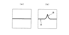
次に、当該光沢面検査装置及び方法による光沢面の欠陥検知理論について説明する。まず、表面欠陥を有しない平面状光沢面に対して斜め方向から帯状の光束を有するレーザー光Yを照射した場合、そのレーザー光Yの反射光は図3(a)に示すように直線状の正反射光のみとなる。一方、凹みを有する平面状光沢面に対して斜め方向から帯状の光束を有するレーザー光Yを照射した場合、そのレーザー光Yの反射光は図3(b)に示すように直線状の正反射光部分Aと凸状の歪み部分Bとを有することとなる。この歪み部分Bの形状及び大きさは表面欠陥の種類及び大きさに対応したものとなる。そのため、この歪み部分Bを画像処理によって認識することで、表面欠陥の有無、種類及び程度の判定が可能となる。
【0033】
なお、本発明の光沢面検査装置及び方法は上記実施形態に限定されるものではなく、例えば投影スクリーン2を設けず、被検査物Xの表面からの反射光を直接カメラ3で撮影することも可能である。
【0034】
【発明の効果】
以上説明したように、本発明の光沢面検査装置及び方法によれば、オートメーション化が可能であり、検査レベル及び速度が格段に高くなることから、大量生産工程のオンライン上に組み込み、生産性を飛躍的に向上することができる。
【図面の簡単な説明】
【図1】本発明の一実施形態に係る光沢面検査方法を示すフロー図である。
【図2】図1の光沢面検査方法を実施するための光沢面検査装置を示す概略構成図である。
【図3】(a)は表面欠陥がない場合の画像データを示す模式図、(b)は表面欠陥が存在する場合の画像データを示す模式図である。
【符号の説明】
1 投光部
2 投影スクリーン
3 カメラ
4 画像処理手段
5 判定手段
6 テーブル
X 被検査物
Y レーザー光
A 正反射光部分
B 歪み部分[0001]
TECHNICAL FIELD OF THE INVENTION
The present invention relates to a glossy surface inspection apparatus and method for inspecting surface defects on a glossy surface.
[0002]
[Prior art]
Today, dry batteries, various household appliances, drinking water, and the like are mass-produced and stored in containers or housings made of metal, plastic, glass, and the like. The surface of such a metal or plastic or glass container or housing is generally glossy.
[0003]
Inspection of surface defects of containers or housings of various products such as the above dry batteries must be performed online in a mass production process because various products are mass-produced. Have been.
[0004]
On the other hand, as non-destructive flaw detection methods for metal surfaces, for example, a fluorescent magnetic particle flaw detection method (see Japanese Patent Application Laid-Open No. H10-282603), a liquid penetration flaw detection method, an ultrasonic flaw detection method (see Japanese Patent Application Laid-Open No. 2002-139479, etc.), radiation A flaw detection method (see JP-A-5-177351), a magnetic flaw detection method (see JP-A-6-201654), and the like have been developed.
[0005]
[Patent Document 1]
Japanese Patent Application Laid-Open No. H10-28063 [Patent Document 2]
JP 2002-139479 A [Patent Document 3]
JP-A-5-177351 [Patent Document 4]
JP-A-6-201654
[Problems to be solved by the invention]
The above-mentioned conventional method for inspecting a glossy surface relies on the skill of an inspector, and thus has errors and misperceptions due to visual observation as fundamental problems, and there are certain restrictions on improving the accuracy and speed of inspection. is there. In addition, in the above-described conventional method for inspecting a glossy surface, it is not easy to visually determine a surface defect due to halation, reflection of illumination, and the like on the glossy surface. Further, in the above-described conventional method for inspecting a glossy surface, it is difficult to determine a stain which can be corrected in a subsequent coating process or the like and a surface defect such as a scratch, and there is an inconvenience that even a problem-free stain is detected.
[0007]
In addition, although the nondestructive flaw detection method for the metal surface described above requires a high level of inspection, it basically performs a relatively long time offline inspection on a large object. It cannot be applied to online inspections in mass production processes such as.
[0008]
The present invention has been made in view of these inconveniences, and an object of the present invention is to provide a glossy surface inspection apparatus and method which can be performed on-line in a mass production process, with extremely high inspection accuracy and speed. .
[0009]
[Means for Solving the Problems]
The invention made in order to solve the above-described problem is a light emitting unit that irradiates a laser beam from a diagonal direction to a glossy surface, a camera that captures reflected light of the laser light on the glossy surface, and an image captured by the camera. The glossy surface inspection apparatus includes image processing means for acquiring distortion of regular reflection light from image data, and determination means for detecting a surface defect on a glossy surface based on distortion of regular reflection light acquired by the image processing means.
[0010]
The glossy surface inspection device uses the fact that if there is a defect such as a scratch or unevenness on the glossy surface, the specular reflection light of the laser beam irradiated from the oblique direction on the glossy surface is distorted. And the type of defect are inspected. Specifically, the glossy surface inspection apparatus irradiates the glossy surface with laser light from an oblique direction by a light emitting unit, captures reflected light of the laser light from the glossy surface by a camera, and images captured by an image processing unit. The distortion of the specular reflection light is obtained from the data, and the determining means detects a surface defect on the glossy surface based on the distortion of the specular reflection light.
[0011]
Therefore, the glossy surface inspection apparatus can prevent an inspection error and an erroneous recognition caused by visual observation such as halation or reflection of illumination, and can greatly improve the accuracy and speed of the inspection. Further, the glossy surface inspection apparatus can determine the type and degree of the surface defect based on the magnitude and shape of the distortion of the regular reflection light acquired by the image processing means. Further, since the glossy surface inspection device does not affect the distortion of the specular reflection light even if there is a dirt on the glossy surface, it is possible to reduce the detection of dirt that can be corrected by a subsequent coating process and has no problem in commercialization. be able to.
[0012]
The inclination angle of the laser light with respect to the normal direction of the glossy surface is preferably 45 ° or more and 85 ° or less. By setting the inclination angle of the laser beam irradiated by the light projecting unit within the above range, distortion of the regular reflection light due to a surface defect becomes remarkable, and inspection accuracy can be improved.
[0013]
It is preferable that the laser beam emitted by the light emitting section has a band-like light beam. By irradiating a laser beam having a band-like light beam in this manner, it is easy to obtain the distortion of the specularly reflected light, and the entire glossy surface can be inspected by scanning in one direction.
[0014]
It is preferable to use a semiconductor laser for the irradiation of the laser beam in the light emitting section. Such a semiconductor laser is preferable in that a laser beam having a sufficient output for observing reflected light on a glossy surface can be obtained with a relatively wide range of devices, and a laser beam around visible light suitable for image processing of the reflected light can be obtained.
[0015]
Further, an invention according to a glossy surface inspection method made to solve the above-mentioned problem includes an irradiation step of irradiating a laser beam from a diagonal direction to a glossy surface, and an imaging step of photographing a reflected light of the laser light on the glossy surface A process for acquiring distortion of specular reflection light from the image data of the reflected light; and a determination step of detecting a surface defect on the glossy surface based on the distortion of the regular reflection light. The glossy surface inspection method, like the above glossy surface inspection apparatus, has remarkably high inspection accuracy and speed, and can be incorporated on-line in a mass production process to dramatically improve productivity.
[0016]
Here, "specular reflection light" means mirror reflection light when there is no defect such as a scratch or unevenness on the glossy surface. "The normal direction of the glossy surface" means the normal direction of the glossy surface assuming that there is no defect.
[0017]
BEST MODE FOR CARRYING OUT THE INVENTION
Hereinafter, embodiments of the present invention will be described in detail with reference to the drawings as appropriate. FIG. 1 is a flowchart showing a glossy surface inspection method according to one embodiment of the present invention, FIG. 2 is a schematic configuration diagram showing a glossy surface inspection device for performing the glossy surface inspection method of FIG. 1, and FIG. (B) is a schematic diagram showing image data when there is no surface defect and when there is a surface defect.
[0018]
The inspection method of the glossy surface shown in FIG. 1 includes an irradiation step (STP1) of irradiating the glossy surface with a laser beam from an oblique direction, an imaging step (STP2) of imaging the reflected light of the laser beam on the glossy surface, It has an image processing step (STP3) for acquiring distortion of regular reflection light from image data, and a determination step (STP4) for detecting a surface defect on a glossy surface based on the distortion of regular reflection light.
[0019]
The glossy surface inspection device shown in FIG. 2 is a device that performs the above-described glossy surface inspection method and inspects the surface (glossy surface) of the inspection object X. Specifically, the glossy surface inspection apparatus includes a light projecting unit 1, a
[0020]
The image processing unit 4 and the
[0021]
The light projecting unit 1 irradiates the surface of the inspection object X placed on the table 6 with the laser beam Y from an oblique direction. As the laser beam transmitting mechanism of the light projecting unit 1, a known technology capable of irradiating the laser beam Y is employed. However, since the glossy surface inspection apparatus is for observing the reflected light of the laser light Y and detecting the surface defect of the inspection object X, the laser light Y may have an output enough to observe the reflected light. Therefore, as the laser light transmitting mechanism of the light projecting unit 1, a semiconductor laser that can irradiate the laser light Y having a wavelength near the visible light suitable for observing the distortion of the reflected light and has a relatively simple mechanism is particularly preferable. preferable.
[0022]
The
[0023]
The camera 3 captures an image projected on the
[0024]
The image processing unit 4 acquires the distortion of the specularly reflected light based on the image data captured by the camera 3. In the image processing means 4, the method of acquiring the distortion of the specular reflected light is as follows: (a) a method of obtaining from the exclusive theoretical sum based on the image data when there is no distortion of the specular reflected light (that is, in the case of specular reflection) , (B) a method of calculating an approximate curve of the regular reflection light of the laser beam Y from the image data, and obtaining a portion deviating from the approximate curve.
[0025]
The
[0026]
The glossy surface inspection apparatus irradiates the surface (glossy surface) of the inspection object X with the laser beam Y from an oblique direction by the light emitting unit 1 (irradiation step STP1), and the camera 3 emits the laser light from the surface of the inspection object X. The reflected light of the light Y is photographed (photographing step STP2), the distortion of the regular reflected light is acquired from the image data photographed by the image processing means 4 (image processing step STP3), and the distortion of the regular reflected light acquired by the determination means 5 is obtained. The surface defect of the inspection object X can be detected based on the above (determination step STP4). In other words, the glossy surface inspection apparatus utilizes the fact that when there is a defect such as a scratch or unevenness on the surface (glossy surface) of the inspection object X, distortion occurs in the specular reflection light of the laser light irradiated from an oblique direction. The image processing unit 4 acquires the distortion of the specular reflection light, and the surface defect of the glossy surface is detected by the
[0027]
Therefore, according to the glossy surface inspection apparatus, automation is possible, and the accuracy and speed of the inspection can be remarkably improved as compared with the conventional visual inspection. Further, according to the glossy surface inspection apparatus, it is possible to determine the type and degree of the surface defect based on the magnitude and shape of the distortion of the regular reflection light acquired by the image processing unit 4. Furthermore, according to the glossy surface inspection apparatus, even if there is dirt on the glossy surface, it does not affect the distortion of the specular reflection light. Only the surface defects that need to be detected can be detected.
[0028]
The lower limit of the inclination angle α of the laser beam Y with respect to the normal direction of the surface of the inspection object X is 45 °, particularly 50 °, more preferably 55 °, and the upper limit of the inclination angle α is 85 °, In particular, it is preferably 80 °, more preferably 75 °. By setting the inclination angle α of the laser beam Y to be equal to or larger than the lower limit as described above, the distortion of the regular reflection light caused by the surface defect of the inspection object X becomes remarkable, and the inspection accuracy of the glossy surface inspection apparatus is improved. be able to. On the other hand, when the inclination angle α of the laser beam Y is equal to or less than the above upper limit, the distortion of the specular reflection light caused by the surface defect of the inspection object X becomes too large, and the light amount of the distorted portion decreases. The inconvenience that the inspection accuracy of the inspection device is reduced can be reduced.
[0029]
The laser beam Y emitted by the light projecting unit 1 preferably has a band-like light beam. By irradiating the laser beam Y having a belt-like light beam in this manner, (a) it is easy to obtain the distortion of the regular reflection light, and the inspection accuracy is improved. (B) The glossy surface is scanned by scanning in one direction. The whole surface can be inspected, and there is an advantage that the inspection speed is improved.
[0030]
As a scanning method of the glossy surface inspection apparatus, (a) a method of moving the table 6 on which the inspection object X is mounted in the XY direction on the surface thereof, and (b) moving the light projecting unit 1 in parallel with the table 6 And (c) a method in which the light projecting unit 1 is driven in a swinging manner to change the irradiation direction of the laser light Y. In the case of changing the irradiation direction of the laser light Y in the above (c), by feeding back the irradiation direction information of the laser light Y to the
[0031]
When scanning the outer peripheral surface of the columnar inspected object X using the laser beam Y having a band-shaped light beam, the light beam surface of the laser beam Y was inclined at a predetermined angle from the longitudinal axis of the inspected object X. It is preferable that the inspection object X be installed in a state where the outer peripheral surface of the inspection object X is obliquely cut by the laser beam Y, and the inspection object X be rotated around the longitudinal axis to scan the entire peripheral surface. According to this scanning method, it is possible to scan the entire peripheral surface by simply rotating the inspection object X by one rotation, and it is possible to inspect a surface defect even if the positioning in the irradiation direction of the laser beam Y is somewhat rough.
[0032]
Next, the theory of defect detection on the glossy surface by the glossy surface inspection apparatus and method will be described. First, when a flat glossy surface having no surface defects is irradiated with a laser beam Y having a band-like luminous flux from an oblique direction, the reflected light of the laser beam Y has a linear shape as shown in FIG. There is only regular reflection light. On the other hand, when a laser light Y having a band-like light beam is irradiated from an oblique direction to a flat glossy surface having a dent, the reflected light of the laser light Y becomes linear regular reflection as shown in FIG. It has a light part A and a convex distortion part B. The shape and size of the distorted portion B correspond to the type and size of the surface defect. Therefore, by recognizing the distorted portion B by image processing, it is possible to determine the presence, type, and degree of a surface defect.
[0033]
It should be noted that the glossy surface inspection apparatus and method of the present invention are not limited to the above-described embodiment. It is possible.
[0034]
【The invention's effect】
As described above, according to the glossy surface inspection apparatus and method of the present invention, automation can be performed, and the inspection level and speed can be significantly increased. It can be dramatically improved.
[Brief description of the drawings]
FIG. 1 is a flowchart illustrating a glossy surface inspection method according to an embodiment of the present invention.
FIG. 2 is a schematic configuration diagram showing a glossy surface inspection apparatus for performing the glossy surface inspection method of FIG.
3A is a schematic diagram illustrating image data when there is no surface defect, and FIG. 3B is a schematic diagram illustrating image data when a surface defect exists.
[Explanation of symbols]
DESCRIPTION OF SYMBOLS 1
Claims (5)
この光沢面におけるレーザー光の反射光を撮影するカメラと、
このカメラで撮影した画像データから正反射光の歪みを取得する画像処理手段と、
この画像処理手段で取得した正反射光の歪みに基づき光沢面の表面欠陥を検出する判定手段と
を備える光沢面検査装置。A light emitting unit that irradiates a laser beam from an oblique direction to a glossy surface,
A camera for capturing the reflected light of the laser light on the glossy surface,
Image processing means for acquiring the distortion of specularly reflected light from image data taken by the camera,
A glossy surface inspection apparatus comprising: a determination unit configured to detect a surface defect on a glossy surface based on distortion of specular light acquired by the image processing unit.
この光沢面におけるレーザー光の反射光を撮影する撮影工程と、
この反射光の画像データから正反射光の歪みを取得する画像処理工程と、
この正反射光の歪みに基づき光沢面の表面欠陥を検出する判定工程と
を有する光沢面検査方法。An irradiation step of irradiating the glossy surface with laser light from an oblique direction,
A photographing process of photographing the reflected light of the laser light on the glossy surface,
An image processing step of obtaining the distortion of the specular reflection light from the image data of the reflection light,
A determining step of detecting a surface defect on a glossy surface based on the distortion of the specular reflection light.
Priority Applications (1)
| Application Number | Priority Date | Filing Date | Title |
|---|---|---|---|
| JP2003159863A JP2004361243A (en) | 2003-06-04 | 2003-06-04 | Apparatus and method for inspecting lustrous surface |
Applications Claiming Priority (1)
| Application Number | Priority Date | Filing Date | Title |
|---|---|---|---|
| JP2003159863A JP2004361243A (en) | 2003-06-04 | 2003-06-04 | Apparatus and method for inspecting lustrous surface |
Publications (1)
| Publication Number | Publication Date |
|---|---|
| JP2004361243A true JP2004361243A (en) | 2004-12-24 |
Family
ID=34052813
Family Applications (1)
| Application Number | Title | Priority Date | Filing Date |
|---|---|---|---|
| JP2003159863A Pending JP2004361243A (en) | 2003-06-04 | 2003-06-04 | Apparatus and method for inspecting lustrous surface |
Country Status (1)
| Country | Link |
|---|---|
| JP (1) | JP2004361243A (en) |
Cited By (2)
| Publication number | Priority date | Publication date | Assignee | Title |
|---|---|---|---|---|
| JP2017506349A (en) * | 2014-01-27 | 2017-03-02 | テクサ・エッセ・ピ・ア | Method and apparatus for determining brake disk deterioration |
| JP6984964B1 (en) * | 2021-02-24 | 2021-12-22 | 株式会社Rist | Surface shape inspection device and surface shape inspection method |
-
2003
- 2003-06-04 JP JP2003159863A patent/JP2004361243A/en active Pending
Cited By (4)
| Publication number | Priority date | Publication date | Assignee | Title |
|---|---|---|---|---|
| JP2017506349A (en) * | 2014-01-27 | 2017-03-02 | テクサ・エッセ・ピ・ア | Method and apparatus for determining brake disk deterioration |
| JP6984964B1 (en) * | 2021-02-24 | 2021-12-22 | 株式会社Rist | Surface shape inspection device and surface shape inspection method |
| WO2022180667A1 (en) * | 2021-02-24 | 2022-09-01 | 株式会社Rist | Surface shape inspection device and surface shape inspection method |
| JP2022129355A (en) * | 2021-02-24 | 2022-09-05 | 株式会社Rist | Surface shape inspection device and surface shape inspection method |
Similar Documents
| Publication | Publication Date | Title |
|---|---|---|
| JP3709426B2 (en) | Surface defect detection method and surface defect detection apparatus | |
| JPWO2008139735A1 (en) | Surface inspection apparatus and surface inspection method | |
| JP2009020000A (en) | Inspection device and method | |
| JP2010025652A (en) | Surface flaw inspection device | |
| TWI695164B (en) | Broadband wafer defect detection system and broadband wafer defect detection method | |
| TWI663392B (en) | System and method for wafer edge inspection with trajectory following edge profile | |
| US10209203B2 (en) | Wafer inspection apparatus and wafer inspection method | |
| JP2006138830A (en) | Surface defect inspection device | |
| JP2010122145A (en) | Silicon wafer defect inspection device | |
| JP2008020371A (en) | Inspection device | |
| JP2006170684A (en) | Method and device for inspecting press failure | |
| JP2004245695A (en) | Image processing method and foreign substance detection apparatus | |
| JP2008021884A (en) | Inspection apparatus | |
| JP2004361243A (en) | Apparatus and method for inspecting lustrous surface | |
| JP2006017685A (en) | Surface defect inspection device | |
| JP5415162B2 (en) | Cylindrical surface inspection equipment | |
| JP4753706B2 (en) | Glossy plane inspection device | |
| JP4783590B2 (en) | Glossy cylindrical surface inspection device | |
| JP2002303583A (en) | Inspection method for container and inspection device for container | |
| JP3078784B2 (en) | Defect inspection equipment | |
| WO2010096407A1 (en) | Polarization imaging | |
| JP2000028535A (en) | Defect inspecting device | |
| JP5367292B2 (en) | Surface inspection apparatus and surface inspection method | |
| JP2009047517A (en) | Inspection apparatus | |
| JPH07146245A (en) | Apparatus and method for detecting foreign matter |
Legal Events
| Date | Code | Title | Description |
|---|---|---|---|
| A621 | Written request for application examination |
Effective date: 20060509 Free format text: JAPANESE INTERMEDIATE CODE: A621 |
|
| A977 | Report on retrieval |
Effective date: 20081209 Free format text: JAPANESE INTERMEDIATE CODE: A971007 |
|
| A131 | Notification of reasons for refusal |
Free format text: JAPANESE INTERMEDIATE CODE: A131 Effective date: 20090106 |
|
| A521 | Written amendment |
Effective date: 20090309 Free format text: JAPANESE INTERMEDIATE CODE: A523 |
|
| A131 | Notification of reasons for refusal |
Effective date: 20091006 Free format text: JAPANESE INTERMEDIATE CODE: A131 |
|
| A521 | Written amendment |
Effective date: 20091204 Free format text: JAPANESE INTERMEDIATE CODE: A523 |
|
| A02 | Decision of refusal |
Free format text: JAPANESE INTERMEDIATE CODE: A02 Effective date: 20100202 |