JP2004357492A - Converter circuit protected from short circuit current - Google Patents
Converter circuit protected from short circuit current Download PDFInfo
- Publication number
- JP2004357492A JP2004357492A JP2004052843A JP2004052843A JP2004357492A JP 2004357492 A JP2004357492 A JP 2004357492A JP 2004052843 A JP2004052843 A JP 2004052843A JP 2004052843 A JP2004052843 A JP 2004052843A JP 2004357492 A JP2004357492 A JP 2004357492A
- Authority
- JP
- Japan
- Prior art keywords
- circuit
- energy storage
- short
- voltage circuit
- converter circuit
- Prior art date
- Legal status (The legal status is an assumption and is not a legal conclusion. Google has not performed a legal analysis and makes no representation as to the accuracy of the status listed.)
- Pending
Links
- 238000004146 energy storage Methods 0.000 claims abstract description 54
- 239000004065 semiconductor Substances 0.000 claims abstract description 29
- 239000003990 capacitor Substances 0.000 claims description 41
- 230000003071 parasitic effect Effects 0.000 description 12
- 230000010355 oscillation Effects 0.000 description 5
- 230000002457 bidirectional effect Effects 0.000 description 2
- 230000006378 damage Effects 0.000 description 2
- 238000001514 detection method Methods 0.000 description 2
- 238000013016 damping Methods 0.000 description 1
- 230000001419 dependent effect Effects 0.000 description 1
- 238000011161 development Methods 0.000 description 1
- 230000018109 developmental process Effects 0.000 description 1
- 238000005516 engineering process Methods 0.000 description 1
- 230000001939 inductive effect Effects 0.000 description 1
- 238000000034 method Methods 0.000 description 1
- 239000007787 solid Substances 0.000 description 1
Images


Classifications
-
- H—ELECTRICITY
- H02—GENERATION; CONVERSION OR DISTRIBUTION OF ELECTRIC POWER
- H02M—APPARATUS FOR CONVERSION BETWEEN AC AND AC, BETWEEN AC AND DC, OR BETWEEN DC AND DC, AND FOR USE WITH MAINS OR SIMILAR POWER SUPPLY SYSTEMS; CONVERSION OF DC OR AC INPUT POWER INTO SURGE OUTPUT POWER; CONTROL OR REGULATION THEREOF
- H02M7/00—Conversion of ac power input into dc power output; Conversion of dc power input into ac power output
- H02M7/003—Constructional details, e.g. physical layout, assembly, wiring or busbar connections
-
- H—ELECTRICITY
- H02—GENERATION; CONVERSION OR DISTRIBUTION OF ELECTRIC POWER
- H02M—APPARATUS FOR CONVERSION BETWEEN AC AND AC, BETWEEN AC AND DC, OR BETWEEN DC AND DC, AND FOR USE WITH MAINS OR SIMILAR POWER SUPPLY SYSTEMS; CONVERSION OF DC OR AC INPUT POWER INTO SURGE OUTPUT POWER; CONTROL OR REGULATION THEREOF
- H02M1/00—Details of apparatus for conversion
- H02M1/32—Means for protecting converters other than automatic disconnection
Abstract
Description
本発明は、パワーエレクトロニクスの分野に関する。本発明は、特許請求の範囲の独立項の前文による短絡電流保護が施されたコンバータ回路に基づいている。 The invention relates to the field of power electronics. The invention is based on a converter circuit provided with short-circuit current protection according to the preamble of the independent claim.
今日、コンバータ回路は、例えば、鉄道用途のための駆動技術、又はソリッド・ステート変換装置におけるような、多様なパワーエレクトロニクス用途に用いられている。このようなコンバータ回路は、通常、短絡電流が発生しないように保護され、該コンバータ回路が損傷又は破壊されるのを防止する。このような短絡電流保護が施されたコンバータ回路は、例えば、「DCリンク・インバータ用途におけるヒューズによる付加されたインダクタンスの決定、駆動及び制御、2001年3月13日−15日、ロンドン」の中に述べられている。この場合、コンバータ回路は、第1のエネルギー蓄積部を有するDC電圧回路サブシステムによって形成される。このDC電圧回路サブシステムは、第1のエネルギー蓄積部と直列に接続された第2のエネルギー蓄積部とヒューズとを有する。この2つのエネルギー蓄積部は、各々がコンデンサの形態であり、各々のコンデンサは、直列に接続されたヒューズを介してDC電圧回路の母線システムに接続される。このコンバータ回路には、各々の対がパワー半導体スイッチを有する少なくとも1対の分岐線が、各々の相に対して設けられ、母線システムを介してDC電圧回路に並列して接続される。ここで、1対の分岐線の1つ又はそれ以上の駆動可能なパワー半導体スイッチ内に短絡電流が生じた場合には、2つのコンデンサは極めて迅速に放電され、短絡電流が、主として、対応する対の分岐線の短絡されたパワー半導体スイッチを介して流れる。各々の場合において、対応するコンデンサの1つのヒューズは、DC電圧回路サブシステム、よってDC電圧回路自体を隔離することによって、主として短絡電流によって影響を受ける対の分岐線及び他の対の分岐線から、この短絡電流をできるだけ迅速に遠ざけるように働く。 Today, converter circuits are used in a variety of power electronics applications, for example, in drive technology for railway applications or in solid state converters. Such converter circuits are usually protected against short-circuit currents and prevent the converter circuit from being damaged or destroyed. Converter circuits with such short-circuit current protection are described, for example, in "Determination, Drive and Control of Added Inductance by Fuses in DC Link Inverter Applications, March 13-15, 2001, London". It is stated in. In this case, the converter circuit is formed by a DC voltage circuit subsystem having a first energy storage. The DC voltage circuit subsystem has a second energy storage unit and a fuse connected in series with the first energy storage unit. The two energy stores are each in the form of capacitors, each of which is connected to the bus system of the DC voltage circuit via a fuse connected in series. The converter circuit is provided with at least one pair of branch lines, each pair having a power semiconductor switch, for each phase and connected in parallel to the DC voltage circuit via a bus system. Here, if a short-circuit current occurs in one or more drivable power semiconductor switches of a pair of branch lines, the two capacitors are discharged very quickly and the short-circuit current mainly depends on the corresponding short-circuit current. It flows through the shorted power semiconductor switch of the pair of branch lines. In each case, one fuse of the corresponding capacitor separates the DC voltage circuit subsystem, and thus the DC voltage circuit itself, from the pair of branch lines primarily affected by the short-circuit current and the other pair of branch lines. Work to keep this short-circuit current away as quickly as possible.
「DCリンク・インバータ用途におけるヒューズによる付加されたインダクタンスの決定、駆動及び制御、2001年3月13日−15日、ロンドン」による、短絡電流保護が施されたコンバータ回路を用いる1つの問題は、2つのヒューズの寄生インダクタンス及び2つのコンデンサの接続が合計されるので、コンデンサと直列に接続された2つのヒューズ及び2つのコンデンサの接続がDC電圧回路をもたらし、よって、短絡電流保護が施されたコンバータ回路が高度に誘導性になることである。この全体の寄生インダクタンスは、2つのコンバータ回路と共に振動経路を形成し、この振動経路は、特にスイッチが切られたときにわずかに減衰し、対応するパワー半導体スイッチが行うあらゆるスイッチング手順により再び振動させられる。全体の寄生インダクタンスに蓄積された電気エネルギーは、このような振動が生じた場合に、スイッチ・オフ電流とほぼ同じ大きさであるこれらの振動の電流振幅をもたらす。これらの振動の減衰、よって、全体の寄生インダクタンスに蓄積された電気エネルギーの損失は、もっぱら、DC電圧回路及び母線システムの2つのコンデンサの無効でない抵抗成分内に流れる電流によって生じる。このことにより、電力損失に対して高い電気負荷及び熱負荷がこれらの成分にもたらされる。さらに、2つのヒューズを用いるために、DC電圧回路サブシステムの設計は、組立てが複雑であり、多くの成分を必要とし、このことは少なからぬ費用をもたらす。さらに、DC電圧回路サブシステムに設けられる2つのヒューズは、多くのスペースを占める。したがって、例えば、電気鉄道における牽引用途に必要とされるような、短絡電流保護が施されたコンバータ回路のための、よりコンパクトな小型の設計は、実行可能ではないか、又は非常に限られた範囲にのみ可能である。 One problem with using converter circuits with short-circuit current protection by "Determining, driving and controlling added inductance by fuses in DC link inverter applications, London, March 13-15, 2001" is: Since the parasitic inductance of the two fuses and the connection of the two capacitors are summed, the connection of the two fuses and the two capacitors connected in series with the capacitor results in a DC voltage circuit, thus providing short-circuit current protection The converter circuit becomes highly inductive. This total parasitic inductance, together with the two converter circuits, forms an oscillating path which is slightly damped, especially when the switch is turned off, and re-oscillated by any switching procedure performed by the corresponding power semiconductor switch. Can be The electrical energy stored in the overall parasitic inductance, when such oscillations occur, results in the current amplitude of these oscillations being approximately the same as the switch-off current. The damping of these oscillations, and thus the loss of electrical energy stored in the overall parasitic inductance, is caused exclusively by the current flowing in the non-ineffective resistance components of the DC voltage circuit and the two capacitors of the bus system. This results in high electrical and thermal loads on these components with respect to power loss. Further, because of the use of two fuses, the design of the DC voltage circuit subsystem is complex to assemble and requires many components, which results in considerable expense. Further, the two fuses provided in the DC voltage circuit subsystem occupy a lot of space. Thus, a more compact and compact design for a converter circuit with short-circuit current protection, for example as required for traction applications in electric railways, is not feasible or very limited Only possible for ranges.
したがって、本発明の目的は、低インダクタンスを有し、成分をほとんど用いずに簡単な方法で製造することができ、スペースをあまり必要としない短絡電流保護が施されたコンバータ回路を提案することである。この目的は、請求項1の特徴によって達成される。本発明の有利な展開は、従属項において説明される。
Accordingly, an object of the present invention is to propose a converter circuit having a low inductance, which can be manufactured in a simple manner with little use of components, and which is provided with a short-circuit current protection which does not require much space. is there. This object is achieved by the features of
本発明による短絡電流保護を有するコンバータ回路が、第1のエネルギー蓄積部と該第1のエネルギー蓄積部と直列に接続された第2のエネルギー蓄積部とヒューズとを有するDC電圧回路サブシステムによって形成されたDC電圧回路を有する。さらに、コンバータ回路には、各々の対がパワー半導体スイッチを有する少なくとも1対の分岐線が、各々の相に設けられ、DC電圧回路と並列に接続される。本発明によると、ヒューズは、第1のエネルギー蓄積部と第2のエネルギー蓄積部の間に接続を形成する。従来技術による短絡電流保護が施されたコンバータ回路と比較すると、ヒューズを省くことができ、よってコンバータ回路の全体の寄生インダクタンスを減少させることができるので、このことは、DC電圧回路、よって低インダクタンスを有する短絡電流保護が施されたコンバータ回路を達成することを有利に可能にする。さらに、有利に減少された全体の寄生インダクタンスは、切り換えられ、特にスイッチがオフにされるときにコンバータ回路の1対の分岐線のパワー半導体スイッチにより引き起こされ、非常に小さな振幅だけ、特に電流振幅を有する電気振動を、全体の寄生インダクタンスとDC電圧回路のエネルギー蓄積部の間に生じさせる。したがって、コンバータ回路の成分にかかる電気負荷及び熱負荷を減少させることができる。 A converter circuit having short-circuit current protection according to the present invention is formed by a DC voltage circuit subsystem having a first energy storage, a second energy storage connected in series with the first energy storage, and a fuse. A DC voltage circuit. Furthermore, the converter circuit is provided with at least one pair of branch lines, each pair having a power semiconductor switch, in each phase and connected in parallel with the DC voltage circuit. According to the invention, the fuse forms a connection between the first energy storage and the second energy storage. Compared with converter circuits with short-circuit current protection according to the prior art, this can be done in a DC voltage circuit, and thus in a low inductance circuit, since the fuse can be omitted and thus the overall parasitic inductance of the converter circuit can be reduced. Advantageously, it is possible to achieve a converter circuit provided with short-circuit current protection. Furthermore, the advantageously reduced overall parasitic inductance is caused by the power semiconductor switches of the pair of branch lines of the converter circuit being switched, especially when the switch is turned off, and only by a very small amplitude, in particular the current amplitude An electric oscillation having the following is generated between the entire parasitic inductance and the energy storage of the DC voltage circuit. Therefore, the electric load and the heat load on the components of the converter circuit can be reduced.
さらに、DC電圧回路サブシステムのためにただ1つのヒューズを使用するために、本発明による短絡電流保護が施されたコンバータ回路の組立て及び設計は、非常に簡単なものであり、成分をほとんど必要とせず、このことは、相当なコスト削減ができることを意味する。さらに、本発明によるコンバータ回路は、最小限のスペースしか必要としないので、有利にコンパクトな設計を有することができる。本発明によるコンバータ回路は、単一の相を供給する用途及び大きいエネルギー蓄積キャパシタンスを有する用途に有利に適している。
本発明のこれら及びさらなる目的、利点、特徴は、図面と共に以下の本発明の好ましい実施形態の詳細な説明から推論することができる。
Furthermore, the use of only one fuse for the DC voltage circuit subsystem makes the assembly and design of the short circuit protected converter circuit according to the present invention very simple and requires little component. Rather, this means that considerable cost savings can be made. Furthermore, the converter circuit according to the invention requires a minimum space, so that it can advantageously have a compact design. The converter circuit according to the invention is advantageously suitable for applications providing a single phase and for applications with large energy storage capacitance.
These and further objects, advantages and features of the present invention can be inferred from the following detailed description of preferred embodiments of the invention in conjunction with the drawings.
図に用いられる参照番号及びそれらの意味は、参照番号のリストに要約して列挙される。原則として、図の同じ部品には、同じ参照番号が与えられる。説明される実施形態は、例として本発明の主題を表すものであり、限定の趣旨を有するものではない。
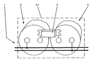
図1は、本発明による短絡電流保護が施されたコンバータ回路の第1の実施形態を示す。さらに、図2は、図1に示される本発明による短絡電流保護が施されたコンバータ回路の第1の実施形態の詳細を示す。図1によると、本発明によるコンバータ回路が、第1のエネルギー蓄積部3と該第1のエネルギー蓄積部3と直列に接続された第2のエネルギー蓄積部4とヒューズ5とを有するDC電圧回路サブシステム2.1により形成されるDC電圧回路1を有する。さらに、図1によるコンバータ回路には、各々の対がパワー半導体スイッチを有する少なくとも1対の分岐線6が、各々の相R、S、Tに対して設けられ、DC電圧回路1と並列に接続されており、すなわち、このように、一般に、各々の対の分岐線6は如何なる所望の数のパワー半導体スイッチも有するので、各々の対の分岐線6に対して単一のパワー半導体スイッチだけを有する実施形態も考えられる。各々の対の分岐線6とDC電圧回路1との間の接続は、該DC電圧回路1の母線システムを介してなされる。各々のパワー半導体スイッチは、駆動可能な双方向性のパワー半導体スイッチの形態、特に、同じく並列に背中合わせに接続されたダイオードを有する絶縁ゲート電極(IGBT)を有するバイポーラトランジスタの形態であることが好ましい。もちろん、このような上述の駆動可能な双方向性パワー半導体は、例えば、GTO、又は対応する回路を有するIGCTのようなターンオフ・サイリスタ、或いは並列に背中合わせに接続されたダイオードを有するパワーMOSFETの形態であってもよい。
The reference numbers used in the figures and their meaning are summarized and listed in a list of reference numbers. In principle, the same parts of the figures are given the same reference numbers. The embodiments described represent by way of example the subject of the invention and are not meant to be limiting.
FIG. 1 shows a first embodiment of a converter circuit provided with short-circuit current protection according to the present invention. Furthermore, FIG. 2 shows details of a first embodiment of the converter circuit with short-circuit current protection according to the invention shown in FIG. According to FIG. 1, a converter circuit according to the present invention comprises a DC voltage circuit having a first
図1に示される本発明によるコンバータ回路の実施形態、及び、図3及び図5により以下に説明される実施形態において、本発明によるコンバータ回路は、例えば、各々の場合において、三相設計より少ないものである。しかしながら、一般に、本発明によるコンバータ回路は、如何なる数の相も有することができ、この場合は、既述のように、対応するパワー半導体スイッチを有する1対の分岐線6が、各々の相に対して設けられる。
本発明によると、ヒューズ5は、第1のエネルギー蓄積部3と第2のエネルギー蓄積部4の間の接続を形成する。短絡電流保護が施された周知のコンバータ回路と比較すると、ヒューズ5を省くことができ、よってコンバータ回路の全体の寄生インダクタンスを減少させることができるので、このことは、DC電圧回路1、よって低インダクタンスの短絡電流保護が施されたコンバータ回路を有利に提供するものである。従来技術によるコンバータ回路のヒューズ5の多くの構成と比較すれば、通常の作動において、本発明によるコンバータ回路のヒューズ5の構成のために、比較的小さい電流だけがヒューズ5を通って流れるので、低い定格電流を用いる安価なヒューズ5を選択することができる。さらに、今や減少された全体の寄生インダクタンスは、切り換えられ、特にスイッチがオフにされるときにコンバータ回路の1対の分岐線6のパワー半導体スイッチにより引き起こされ、非常に小さな振幅だけ、特に電流振幅を有する電気振動を、全体の寄生インダクタンスとDC電圧回路1のエネルギー蓄積部3、4の間に生じさせる。したがって、コンバータ回路のさらに別の成分にかかる電気負荷及び熱負荷を有利に減少させることができる。
In the embodiment of the converter circuit according to the invention shown in FIG. 1 and in the embodiments described below with reference to FIGS. 3 and 5, the converter circuit according to the invention is, for example, in each case less than a three-phase design Things. However, in general, the converter circuit according to the invention can have any number of phases, in which case, as already mentioned, a pair of
According to the invention, the
1対の分岐線6の1つ又はそれ以上の駆動可能なパワー半導体スイッチにおいて生じる短絡電流の場合には、2つのエネルギー蓄積部3、4は、極めて迅速に放電し、短絡電流は、主として、対応する対の分岐線6の短絡されたパワー半導体スイッチを通って流れる。2つのエネルギー蓄積部3、4の間の接続を形成するヒューズ5は、今や、DC電圧回路サブシステム2.1を隔離することによって、できるだけ迅速にこの短絡電流を遮断し、よって、該短絡電流を主に影響を受ける対の分岐線6及び他の対の分岐線6から遠ざける目的を有する。ヒューズ5は、それらが十分に迅速であり、それらの構成のために低インダクタンスでもあるので、ヒューズ・リンクの形態であることが好ましい。
In the event of a short-circuit current occurring in one or more drivable power semiconductor switches of a pair of
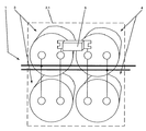
図1及び図2によると、DC電圧回路サブシステム2.1の第1のエネルギー蓄積部3が1つのコンデンサを有し、該DC電圧回路サブシステム2.1の第2のエネルギー蓄積部4が1つのコンデンサを有する。図3に示されるような本発明による短絡電流保護が施されたコンバータ回路の第2の実施形態、及び、図3に示されるような本発明による短絡電流保護が施されたコンバータ回路の第2の実施形態の図4に示されるような詳細において、DC電圧回路サブシステム2.1の第1のエネルギー蓄積部3は、2つのコンデンサを有し、該DC電圧回路サブシステム2.1の第2のエネルギー蓄積部4は、同様に2つのコンデンサを有する。このように、一般に、DC電圧回路サブシステム2.1の第1のエネルギー蓄積部3は、少なくとも1つのコンデンサを有し、該DC電圧回路サブシステム2.1の第2のエネルギー蓄積部4は、同様に少なくとも1つのコンデンサを有することが考えられる。図3及び図4によると、2つ又はそれ以上のコンデンサを有するDC電圧回路サブシステム2.1の第1のエネルギー蓄積部3の場合には、コンデンサは並列に接続される。さらに、図3及び図4によると、2つ又はそれ以上のコンデンサを有するDC電圧回路サブシステム2.1の第2のエネルギー蓄積部4の場合にも、コンデンサは並列に接続される。上述のコンデンサの並列回路は、DC電圧回路サブシステム2.1のキャパシタンス、よってDC電圧回路1自体のキャパシタンスを有利に増加させる。代わりに、2つ又はそれ以上のコンデンサを有する第1のエネルギー蓄積部3の場合には、コンデンサが直列に接続されることになり、2つ又はそれ以上のコンデンサを有する第2のエネルギー蓄積部4の場合には、コンデンサが同様に直列に接続されることになることも考えられる。DC電圧回路サブシステム2.1の全体の電圧は、各々のコンデンサの両端にかかる個々の電圧の和であるので、上述のコンデンサの直列回路は、DC電圧回路サブシステム2.1の電圧、よってDC電圧回路1自体の電圧を有利に増加させることができる。
According to FIGS. 1 and 2, the first
図1及び図3によると、各々の場合において、二相R、S、Tが、第1の駆動可能な短絡素子8を介して互いに接続される。この場合には、それぞれの相R、S、T間の接続は、低インピーダンス値を有し、すなわち、非常に低い直列インピーダンスだけを有する。1つ又はそれ以上の相R、S、Tへの短絡の場合、この第1の駆動可能な短絡素子8は、該相R、S、Tからの、すなわち、例えば電力供給システムからの短絡によって引き起こされる短絡電流が、対応する対の分岐線6のパワー半導体スイッチを通って流れるのを防止し、特に、並列に背中合わせに接続されたダイオードを通る、これに応じて設計されたパワー半導体スイッチの場合、或いは短絡電流が低い振幅で流れることを可能にするだけなので、該パワー半導体スイッチは、それ以上損傷又は破壊されず、或いは全く損傷又は破壊されない。第1の短絡素子8は、短絡電流が検知装置によって1対の分岐線6内又は該1対の分岐線6上で検知されたときに駆動され、この場合の第1の駆動可能な短絡素子8は、各々の場合において該第1の短絡素子8に接続された二相R、S、Tを短絡させる。本発明による三相コンバータ回路の場合、各々の場合において、単に二相R、S、Tに対して1つの第1の短絡素子8を設けることも考えられる。有利に、このような第1の駆動可能な短絡素子8は、並列に背中合わせに接続された2つの駆動可能なパワー半導体から形成され、各々が、ディスク・サイリスタ又はGTOのような圧力接点を有する。第1の駆動可能な短絡素子8は、トライアックの形態としてもよい。
According to FIGS. 1 and 3, in each case the two phases R, S, T are connected to one another via a first drivable short-
図1及び図3によると、本発明によるコンバータ回路が、DC電圧回路サブシステム2.1と並列に接続された少なくとも1つの第2の駆動可能な短絡素子7を有する。1対の分岐線6の1つ又はそれ以上の駆動可能なパワー半導体スイッチにおける短絡の場合には、この第2の駆動可能な短絡素子7は、短絡によって引き起こされた、エネルギー蓄積部3、4又は相R、S、Tからの短絡電流、すなわち、例えば電力供給システムからの短絡電流が、対応する対の分岐線6の短絡されたパワー半導体スイッチを通って非常に短い間流れるだけであり、その後、短絡されたパワー半導体スイッチがそれ以上損傷又は破壊されないように、第2の短絡素子7を通って分流されることを保証する。第2の短絡素子7が、検知装置によって1対の分岐線6内又は該1対の分岐線6上で検知されたときに駆動され、この場合における第2の駆動可能な短絡素子7は、DC電圧回路1の対応するスイッチングによって短絡される。第2の短絡素子7が駆動する際、対応するパワー半導体スイッチの場合には、並列に背中合わせに接続されたダイオードは、例えば、第1の短絡素子8が設けられなったときに短絡電流を受ける。有利に、このような第2の駆動可能な短絡素子7は、ディスク・サイリスタ又はGTOのような圧力接点を有する駆動可能なパワー半導体の形態である。この構成を有する第2の駆動可能な短絡素子7は、1対の分岐線6及び母線システムのDC電圧回路1への接続部に直接配置されることが好ましく、その結果、スペースをさらに節約することができ、本発明による低インダクタンスのコンバータ回路を達成することができる。DC電圧回路サブシステム2.1、よってDC電圧回路1の詳細に上述された短絡の場合には、電流容量を増加させるために、該DC電圧回路サブシステム2.1と並列に接続された2つ又はそれ以上の第2の駆動可能な短絡素子7を設けることもできる。第2の短絡素子7のさらに別の利点は、DC電圧回路サブシステム2.1の2つのエネルギー蓄積部3、4が、第2の短絡素子7のスイッチングによって初期段階に放電され、よって、ヒューズ5がより迅速に応答できることである。ヒューズ5の初期の応答は、主として短絡により影響される対の分岐線6及び他の対の分岐線6を、それ以上の損傷又は破壊からより効果的に保護することができる。
According to FIGS. 1 and 3, the converter circuit according to the invention has at least one second drivable short-
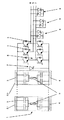
図5は、本発明による短絡電流保護が施されたコンバータ回路の第3の実施形態を示す。図5によるコンバータ回路は、図1及び図3に示され、上で詳述されたコンバータ回路の実施形態と、DC電圧回路1が前のDC電圧回路サブシステム2.1に加えて少なくとも1つのさらなるDC電圧回路サブシステム2.2、・・・、2.nを有し、DC電圧回路サブシステム2.1・・・、2.nが、互いに並列に接続されているという点で異なる。図3におけるように、図5によると、各々のDC電圧回路サブシステム2.1、・・・、2.nは、関連した第1のエネルギー蓄積部3に対して2つ又はそれ以上のコンデンサを有することができ、関連した第2のエネルギー蓄積部4に対して2つ又はそれ以上のコンデンサを有することができる。図3におけるように、図5によると、各々のDC電圧回路サブシステム2.1、・・・、2.nの第1及び第2のエネルギー蓄積部3、4のコンデンサは、この場合には、各々が並列に接続されることが好ましい。図3に示されるような本発明によるコンバータ回路の第2の実施形態の説明において既述されたように、コンデンサの並列回路は、それぞれのDC電圧回路サブシステム2.1、・・・、2.nのキャパシタンス、よってDC電圧回路1自体のキャパシタンスを有利に増加させる。代わりに、同じく図3に示されるような本発明によるコンバータ回路の第2の実施形態の説明において既述されるように、各々のDC電圧回路サブシステム2.1、・・・、2.nの第1及び第2のエネルギー蓄積部3、4のコンデンサに対して、各々が直列に接続されることも考えられる。コンデンサのこの直列回路は、それぞれのDC電圧回路サブシステム2.1、・・・、2.nの電圧、よってDC電圧回路1自体の電圧を有利に増加させることができる。当然、各々のDC電圧回路サブシステム2.1、・・・、2.nの第1のエネルギー蓄積部3及び第2のエネルギー蓄積部は、各々の場合において、1つだけのコンデンサを有することもできる。図1及び図3におけるように、図5によるコンバータ回路の実施形態において、第1の駆動可能な短絡素子7、及び各々の場合において二相R、S、Tに対して、第2の駆動可能な短絡素子8が設けられ、そこで言及された利点を有する第1及び第2の駆動可能な短絡素子7、8の詳細な説明が図1及び図3で説明される。もちろん、図1乃至図4におけるように、図5に示されるような本発明によるコンバータ回路の実施形態において、各々のDC電圧回路サブシステム2.1、・・・、2.nに対してヒューズ5が設けられ、関連したDC電圧回路サブシステム2.1、・・・、2.nの第1のエネルギー蓄積部3と該DC電圧回路サブシステム2.1、・・・、2.nの第2のエネルギー蓄積部4との間に接続を形成する。
FIG. 5 shows a third embodiment of a converter circuit provided with short-circuit current protection according to the present invention. The converter circuit according to FIG. 5 comprises the embodiment of the converter circuit shown in FIGS. 1 and 3 and detailed above, wherein the
前のDC電圧回路サブシステム2.1に加えて、さらに別の並列接続されたDC電圧回路サブシステム2.2、・・・、2.nを設ける利点は、DC電圧回路サブシステム2.1、・・・、2.nの並列回路によって、全体の寄生インダクタンスをさらに減少させ得ることである。このことは、最初に述べた、全体の寄生インダクタンスとDC電圧回路1の第1及び第2のエネルギー蓄積部3、4の全ての間の電気振動の振幅をさらに減少させ得ることを有利に保証する。このように、コンバータ回路のさらに別の成分にかかる電気負荷及び熱負荷を有利に最小限まで減少させることができる。
In addition to the previous DC voltage circuit subsystem 2.1, yet another parallel connected DC voltage circuit subsystem 2.2,. n are provided by DC voltage circuit subsystems 2.1,. With n parallel circuits, the overall parasitic inductance can be further reduced. This advantageously guarantees that the first mentioned, the overall parasitic inductance and the amplitude of the electrical oscillation between all of the first and
さらに別の利点は、DC電圧回路サブシステム2.1、・・・、2.nの1つの中の短絡の場合には、短絡により影響を受けるDC電圧回路サブシステム2.1、・・・、2.nだけが、関連したヒューズ5によって、残りのDC電圧回路1から隔離されるという事実である。したがって、これらの冗長なDC電圧回路サブシステム2.1、・・・、2.nが高度の選択性の達成を有利に可能にするので、短絡により影響を受けない残りのDC電圧回路サブシステム2.1、・・・、2.nを用いて、実際に如何なる制限もなく、本発明によるコンバータ回路を作動させ続けることができる。本発明による短絡電流保護が施されたコンバータ回路が、例えば、電気鉄道の牽引用途のために用いられた場合には、こうしたコンバータ回路の連続作動が特に必須である。
本発明による短絡電流保護が施されたコンバータ回路は、全体的に取付けやすく簡単であり、よって低コストの構成によって特徴付けられ、最小限の数の成分で作動することができ、さらに、省スペースの、よってコンパクトな方法で設計することができる。
Yet another advantage is that the DC voltage circuit subsystem 2.1,. n in the case of a short circuit in one of the DC voltage circuit subsystems 2.1,. It is the fact that only n is isolated from the rest of the
The converter circuit with short-circuit current protection according to the present invention is generally easy to install and simple, and thus is characterized by a low-cost configuration, can operate with a minimum number of components, and furthermore saves space. Therefore, it can be designed in a compact way.
1:DC電圧回路
2.1、・・・、2.n:DC電圧回路サブシステム
3:第1のエネルギー蓄積部
4:第2のエネルギー蓄積部
5:ヒューズ
6:対の分岐線
7:第2の駆動可能な短絡素子
8:第1の駆動可能な短絡素子
1: DC voltage circuit 2.1, ..., 2. n: DC voltage circuit subsystem 3: first energy storage unit 4: second energy storage unit 5: fuse 6: pair of branch lines 7: second drivable short-circuit element 8: first drivable Short-circuit element
Claims (9)
前記第2のエネルギー蓄積部(4)が少なくとも1つのコンデンサを有する、
ことを特徴とする請求項1に記載のコンバータ回路。 Said first energy storage section (3) has at least one capacitor;
The second energy storage section (4) has at least one capacitor;
The converter circuit according to claim 1, wherein:
第2のエネルギー蓄積部(4)が2つ又はそれ以上のコンデンサを有する場合には、前記コンデンサが並列に接続された、
ことを特徴とする請求項2に記載のコンバータ回路。 If the first energy storage (3) has two or more capacitors, said capacitors are connected in parallel;
If the second energy storage (4) has two or more capacitors, said capacitors are connected in parallel;
3. The converter circuit according to claim 2, wherein:
第2のエネルギー蓄積部(4)が2つ又はそれ以上のコンデンサを有する場合には、前記コンデンサが直列に接続された、
ことを特徴とする請求項2に記載のコンバータ回路。 If the first energy storage (3) has two or more capacitors, said capacitors are connected in series;
When the second energy storage (4) has two or more capacitors, said capacitors are connected in series;
3. The converter circuit according to claim 2, wherein:
Applications Claiming Priority (1)
| Application Number | Priority Date | Filing Date | Title |
|---|---|---|---|
| EP03405138A EP1453192B1 (en) | 2003-02-28 | 2003-02-28 | Inverter circuit with short cicuit protection |
Publications (2)
| Publication Number | Publication Date |
|---|---|
| JP2004357492A true JP2004357492A (en) | 2004-12-16 |
| JP2004357492A5 JP2004357492A5 (en) | 2007-03-08 |
Family
ID=32749037
Family Applications (1)
| Application Number | Title | Priority Date | Filing Date |
|---|---|---|---|
| JP2004052843A Pending JP2004357492A (en) | 2003-02-28 | 2004-02-27 | Converter circuit protected from short circuit current |
Country Status (6)
| Country | Link |
|---|---|
| US (1) | US7049787B2 (en) |
| EP (1) | EP1453192B1 (en) |
| JP (1) | JP2004357492A (en) |
| CN (1) | CN100492834C (en) |
| AT (1) | ATE467944T1 (en) |
| DE (1) | DE50312705D1 (en) |
Cited By (4)
| Publication number | Priority date | Publication date | Assignee | Title |
|---|---|---|---|---|
| JP2008503194A (en) * | 2004-06-18 | 2008-01-31 | アーベーベー・シュバイツ・アーゲー | Method for ground fault handling in converter circuit for switching of three voltage levels |
| JP2013183635A (en) * | 2012-03-02 | 2013-09-12 | Alstom Transport Sa | Feed chain for synchronous electric machine, electric traction system comprising such feed chain, and control method for such feed chain |
| JP2015018856A (en) * | 2013-07-09 | 2015-01-29 | 株式会社Ihi | Semiconductor power module |
| KR20210063091A (en) * | 2019-11-22 | 2021-06-01 | 엘지전자 주식회사 | Power conversion apparatus preventing damage of swithching element due to overcurrent |
Families Citing this family (8)
| Publication number | Priority date | Publication date | Assignee | Title |
|---|---|---|---|---|
| US7054173B2 (en) * | 2003-05-07 | 2006-05-30 | Toshiba International Corporation | Circuit with DC filter having a link fuse serially connected between a pair of capacitors |
| FI116175B (en) * | 2003-12-19 | 2005-09-30 | Abb Oy | Method and device for protecting drives |
| JP2006238626A (en) * | 2005-02-25 | 2006-09-07 | Toshiba Corp | Power conversion device for electric car |
| CN101924353B (en) * | 2010-09-14 | 2012-08-08 | 中国船舶重工集团公司第七一二研究所 | Overcurrent electronic protection module for high-voltage integrated gate commutated thyristor (IGCT) and short-circuit current protection method |
| CN104871418B (en) * | 2012-12-25 | 2017-03-29 | 丰田自动车株式会社 | Semiconductor device |
| FR3030140B1 (en) * | 2014-12-16 | 2017-01-27 | Alstom Transp Tech | ELECTRICAL TRACTION SYSTEM FOR A RAILWAY VEHICLE; SAFETY METHOD IMPLEMENTED BY THIS SYSTEM |
| CN109149524A (en) * | 2018-09-20 | 2019-01-04 | 新誉轨道交通科技有限公司 | A kind of inverter protection system and inverter |
| CN113471937A (en) * | 2021-06-23 | 2021-10-01 | 中国科学院合肥物质科学研究院 | Quick protection circuit suitable for high-power voltage source type converter |
Family Cites Families (6)
| Publication number | Priority date | Publication date | Assignee | Title |
|---|---|---|---|---|
| US4779034A (en) * | 1986-08-07 | 1988-10-18 | Shepard Jr Francis H | Forced commutation for variable speed motor |
| US5091840A (en) * | 1990-08-14 | 1992-02-25 | General Electric Company | Power conversion scheme employing shorting means to control current magnitude |
| US5365424A (en) * | 1991-07-10 | 1994-11-15 | Kenetech Windpower, Inc. | High power laminated bus assembly for an electrical switching converter |
| US5450306A (en) * | 1992-12-07 | 1995-09-12 | Square D Company | Closed loop pulse width modulator inverter with volt-seconds feedback control |
| JPH06311730A (en) * | 1993-04-21 | 1994-11-04 | Fujitsu Ltd | Power supply filter circuit |
| JP2001057782A (en) * | 1999-08-11 | 2001-02-27 | Yaskawa Electric Corp | Power converter |
-
2003
- 2003-02-28 AT AT03405138T patent/ATE467944T1/en active
- 2003-02-28 DE DE50312705T patent/DE50312705D1/en not_active Expired - Lifetime
- 2003-02-28 EP EP03405138A patent/EP1453192B1/en not_active Expired - Lifetime
-
2004
- 2004-02-20 US US10/781,647 patent/US7049787B2/en not_active Expired - Lifetime
- 2004-02-27 JP JP2004052843A patent/JP2004357492A/en active Pending
- 2004-02-27 CN CNB2004100082578A patent/CN100492834C/en not_active Expired - Lifetime
Cited By (5)
| Publication number | Priority date | Publication date | Assignee | Title |
|---|---|---|---|---|
| JP2008503194A (en) * | 2004-06-18 | 2008-01-31 | アーベーベー・シュバイツ・アーゲー | Method for ground fault handling in converter circuit for switching of three voltage levels |
| JP2013183635A (en) * | 2012-03-02 | 2013-09-12 | Alstom Transport Sa | Feed chain for synchronous electric machine, electric traction system comprising such feed chain, and control method for such feed chain |
| JP2015018856A (en) * | 2013-07-09 | 2015-01-29 | 株式会社Ihi | Semiconductor power module |
| KR20210063091A (en) * | 2019-11-22 | 2021-06-01 | 엘지전자 주식회사 | Power conversion apparatus preventing damage of swithching element due to overcurrent |
| KR102318940B1 (en) * | 2019-11-22 | 2021-10-28 | 엘지전자 주식회사 | Power conversion apparatus preventing damage of swithching element due to overcurrent |
Also Published As
| Publication number | Publication date |
|---|---|
| DE50312705D1 (en) | 2010-06-24 |
| CN1538607A (en) | 2004-10-20 |
| US20040170034A1 (en) | 2004-09-02 |
| EP1453192B1 (en) | 2010-05-12 |
| CN100492834C (en) | 2009-05-27 |
| ATE467944T1 (en) | 2010-05-15 |
| EP1453192A1 (en) | 2004-09-01 |
| US7049787B2 (en) | 2006-05-23 |
Similar Documents
| Publication | Publication Date | Title |
|---|---|---|
| US7940503B2 (en) | Power semiconductor arrangement including conditional active clamping | |
| KR101853001B1 (en) | Modular multiple converter comprising reverse conductive power semiconductor switches | |
| US8149555B2 (en) | Short-circuit current limiter | |
| JP4313658B2 (en) | Inverter circuit | |
| JP2010512135A (en) | Semiconductor protective element for controlling DC side short circuit of voltage source inverter | |
| JP6646870B2 (en) | Chopper device | |
| JP2004357492A (en) | Converter circuit protected from short circuit current | |
| CN113258809A (en) | Method for short-circuiting sub-modules of a faulty converter and power converter supporting the method | |
| JP2000350465A (en) | Three-level inverter | |
| JP2006141168A (en) | Power conversion apparatus | |
| JP2007116790A (en) | Inverter apparatus | |
| JP2004242475A (en) | Driving system for switching device | |
| US20150318690A1 (en) | Submodule for limiting a surge current | |
| CN111164746A (en) | Semiconductor assembly with fault protection | |
| JP2010115045A (en) | Inverter device in power converter | |
| JPH10164854A (en) | Power converter | |
| US20200083800A1 (en) | Artificial stable short circuit failure mode function by using parallel modules for each switching function | |
| JPH10126961A (en) | Current limiting apparatus | |
| JP4946103B2 (en) | Power converter | |
| US20220345125A1 (en) | Circuit arrangement for controlling a plurality of semiconductor switches connected in parallel | |
| JP2004260981A (en) | Power converting device and electric machine system utilizing it | |
| WO2019145044A1 (en) | Protection of switching cells for a voltage source converter | |
| JP2005531277A (en) | Circuit device with voltage intermediate circuit converter | |
| US11962291B2 (en) | Driver circuit for a low inductive power module and a low inductive power module with enhanced short circuit withstand capability | |
| JP2000354383A (en) | Three level inverter |
Legal Events
| Date | Code | Title | Description |
|---|---|---|---|
| A521 | Request for written amendment filed |
Free format text: JAPANESE INTERMEDIATE CODE: A523 Effective date: 20070124 |
|
| A621 | Written request for application examination |
Free format text: JAPANESE INTERMEDIATE CODE: A621 Effective date: 20070124 |
|
| A977 | Report on retrieval |
Free format text: JAPANESE INTERMEDIATE CODE: A971007 Effective date: 20081127 |
|
| A131 | Notification of reasons for refusal |
Free format text: JAPANESE INTERMEDIATE CODE: A131 Effective date: 20081208 |
|
| A02 | Decision of refusal |
Free format text: JAPANESE INTERMEDIATE CODE: A02 Effective date: 20090511 |