JP2004352020A - Front wheel supporting mechanism - Google Patents
Front wheel supporting mechanism Download PDFInfo
- Publication number
- JP2004352020A JP2004352020A JP2003150566A JP2003150566A JP2004352020A JP 2004352020 A JP2004352020 A JP 2004352020A JP 2003150566 A JP2003150566 A JP 2003150566A JP 2003150566 A JP2003150566 A JP 2003150566A JP 2004352020 A JP2004352020 A JP 2004352020A
- Authority
- JP
- Japan
- Prior art keywords
- front wheel
- suspension
- support mechanism
- vertical
- braking
- Prior art date
- Legal status (The legal status is an assumption and is not a legal conclusion. Google has not performed a legal analysis and makes no representation as to the accuracy of the status listed.)
- Pending
Links
Images


Abstract
Description
【0001】
【発明の属する技術分野】
本発明は、例えば、自転車やバイク等の二輪車等に用いられ、懸架装置を備えている前輪支持機構に関する。
【0002】
【従来の技術】
走行している車輪には、例えば、タイヤの変形、路面の小さな凹凸、前後輪の速度差等が原因となって、前後方向の衝撃や振動が生じる。この前後力は、路面が悪くなり車速が大きくなる程その影響が大きくなるのであるが、従来の懸架装置は、高速化に伴うこのような前後方向の衝撃や振動に対して、充分な緩衝性能を有していなかった。このような問題を解決すべく、本発明者により、車輪に前後方向の円運動を取り入れた偏心保持体を有する懸架装置(例えば、特許文献1〜3参照)が提案されている。特許文献1、2に記載の懸架装置によれば、前後方向の衝撃や振動に対して充分な緩衝性能を発揮することができ、特許文献3に記載の懸架装置によれば、さらに、上下方向の衝撃や振動に対しても緩衝性能を発揮することができる。
【0003】
【特許文献1】
特公昭49−17161号公報
【特許文献2】
特公昭50−13521号公報
【特許文献3】
特許第2524908号公報
【0004】
【発明が解決しようとする課題】
ところで、近年、自転車の世界についても高速化の波が押し寄せてきている。これは、日常用の自転車においても例外ではない。すなわち、超軽量の車体や、細くて高圧のタイヤの開発や、多段変速機の進歩等により、自転車においても小型オートバイ並みの速度で走行することが可能になってきており、このような場合、凹凸のある路面等を走行する際に車体に加わる衝撃や振動は非常に大きくなる。走行時に車体に加わる衝撃や振動が大きくなると、乗り心地が悪化して乗員に疲労が生じるだけではなく、前進抵抗力が増加して速度が低下し、さらには、スリップの発生や、スリップ等に伴うタイヤの粉塵公害をも引き起こすおそれがある。このような問題は、自転車においてのみならず、バイク等を含む二輪車や三輪車等においても生じる問題であった。特許文献1〜3の懸架装置は、いずれも前後方向の衝撃や振動に対して充分な緩衝性能を発揮し得るが、上下方向の衝撃や振動に対する緩衝性能については、このような近年の高速化に伴う走行時における衝撃や振動の増大を考慮すれば、未だ改善の余地があった。
【0005】
本発明は、上述した課題に鑑みてなされたものであり、その目的は、前後方向の衝撃や振動に対する緩衝性能のみならず、上下方向の衝撃や振動に対する緩衝機能を充分に発揮することが可能であり、衝撃や振動による疲労を軽減して乗り心地を改善することができ、さらに、前進抵抗力を軽減してさらなる高速化を図ることができるとともに、スリップを防止することができ、スリップ等に伴うタイヤの粉塵公害を防止することも可能な前輪支持機構を提供することにある。
【0006】
【課題を解決するための手段】
上述した課題を解決するために、本発明は、以下のようなものを提供する。
(1)前輪(例えば、前輪6)のフロントフォーク(例えば、フロントフォーク5)に設けられ、当該前輪を支持する懸架装置を支持する前輪支持機構であって、
上記懸架装置は、上記フロントフォークと一体的に設けられ、上記前輪に対する上下方向の振動を緩衝する上下動サスペンション(例えば、上下動サスペンション150)と、
上記上下動サスペンションの下端位置に揺動自在に設けられ、上記前輪に対する前後方向の振動を緩衝する前後動サスペンション(例えば、偏心保持体10)とを備えることを特徴とする前輪支持機構(図2、3参照)。
【0007】
(1)の発明によれば、前後動サスペンションによって前輪に加わる前方からの衝撃を緩和することができるとともに、上下動サスペンションによって前輪に加わる真下からの衝撃を緩和することができるため、衝撃や振動による疲労を軽減して乗り心地を改善することができる。
【0008】
さらに、前進抵抗力を軽減してさらなる高速化を図ることができるとともに、スリップを防止することができ、スリップ等に伴うタイヤの粉塵公害を防止することも可能になる。
【0009】
(2) 上記(1)に記載の前輪支持機構であって、
上記上下動サスペンション(例えば、上下動サスペンション150)は、上記前輪に対して上下方向に設けられた剛性部(例えば、鉛直支持部材4)と、上記剛性部に対して上下方向に摺動自在に設けられた緩衝部(例えば、緩衝部7)と、上記緩衝部の端部位置に設けられた軸支部(例えば、軸支部30)とを有することを特徴とする(図2参照)。
【0010】
(2)の発明によれば、緩衝部が剛性部に対して上下方向に摺動自在に設けられているため、すべり摩擦を防止することが可能であり、上下方向の振動や衝撃に対して充分な緩衝性能を発揮することができる。
【0011】
(3) 上記(2)に記載の前輪支持機構であって、
上記前後動サスペンション(例えば、偏心保持体10)は、その一端部(例えば、軸部23)を上記軸支部に対して揺動自在に設けるとともに、他端部を上記前輪の車軸(例えば、車軸22)に対して回動自在に支持することを特徴とする(図3参照)。
【0012】
(3)の発明によれば、前輪に衝撃が加わったとき、上記一端部を中心として、前輪を後方へ円運動させて逃がすことができるため、前後方向の衝撃や振動に対する緩衝性能と、上下方向の衝撃や振動に対する緩衝性能とをさらに向上させることができる。
【0013】
(4) 上記(1)〜(3)のいずれか1に記載の前輪支持機構であって、
上記上下動サスペンションの上部には、前輪(例えば、前輪6)を制動する制動装置(例えば、制動装置200)が設けられ、
上記制動装置は、前輪に設けられた制動面(例えば、リムの側面62a)を、上記制動装置が備える制動部材(例えば、ブレーキシュー63)により制動を行うものであることを特徴とする(図7参照)。
【0014】
(4)の発明によれば、懸架装置の作用による前輪の移動距離が最も短い部分である車軸の直上方向に、制動装置が設けられているため、例えば、前輪の制動面(例えば、前輪のリムの側面等)の幅を広くしたり、制動装置の制動部材(例えば、前輪のブレーキシュー等)の形状を調整したりするというように専用品を製造することなく、従来から用いられている車輪や制動装置を用いることができ、製造コストを低減することができる。
【0015】
(5) 上記(1)〜(4)のいずれか1に記載の前輪支持機構であって、
上記上下動サスペンションと上記前後動サスペンションとの間に減衰機構が設けられたことを特徴とする。
【0016】
(5)の発明によれば、懸架装置の作用やハンドル操作等の多方向への運動に伴って発生するおそれがある自励振動や共振等の予期しない不都合な振動を防止することができ、操作性を向上させるとともに安全性を高めることができる。
【0017】
【発明の実施の形態】
[第1実施形態]
本発明の前輪支持機構の第1実施形態について図面に基づいて説明する。
以下においては、本発明に係る前輪支持機構に好適な実施形態として、本発明を自転車に適用した場合を示す。
【0018】
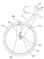
図1は、第1実施形態に係る前輪支持機構を備えた自転車を模式的に示す全体側面略図である。
自転車のフロントフォーク5には、前輪6を支持する懸架装置100が設けられている。この懸架装置100は、前輪6に対する上下方向の振動を緩衝する上下動サスペンション150と、上下動サスペンション150の下端位置に設けられた偏心保持体(前後動サスペンション)10とを備えている。偏心保持体10は、前輪6に対する前後方向の振動を緩衝するものである。また、上下動サスペンション150の上部には、前輪6を制動する制動装置200が設けられている。
【0019】
図2は、第1実施形態に係る前輪支持機構を模式的に示す側面図である。
フロントフォーク5に設けられた懸架装置100は、上下動サスペンション150と、偏心保持体10とを備えている。上下動サスペンション150は、前輪6に対して上下方向に設けられた鉛直支持部材(剛性部)4と、鉛直支持部材4に対して上下方向に摺動自在に設けられた緩衝部7と、緩衝部7の端部位置に設けられた軸支部30とを有するものである。緩衝部7は、ベローズ内にコイルスプリングと油圧ダンパとが設けられて構成される。また、上下動サスペンション150の上部には、キャリパブレーキからなる制動装置200が設けられている。
【0020】
また、フロントフォーク5の上端側には、円筒形状のヘッドパイプ3が設けられ、ヘッドパイプ3には、ハンドルを備えたハンドル支柱2が差し込まれている。このハンドル支柱2は、引上ボルト(図示せず)の先に付いた臼のくさび作用によって、ハンドル支柱2の芯線を中心にハンドルが旋回可能となるように、ヘッドパイプ3に連結されている。また、図中に示すように、ハンドル支柱2は、その芯線の下側を進行方向側へ向けて傾斜するように設けられている。
【0021】
第1実施形態に係る前輪支持機構では、上下動サスペンション150の緩衝部7が上下方向に設けられているため、すべり摩擦を防止することが可能であり、上下方向の衝撃や振動に対する緩衝性能が低下することがなく、充分に緩衝性能を発揮することができる。第1実施形態においては、上下動サスペンション150は、コイルスプリングと油圧ダンパとが設けられた緩衝部を有しているが、本発明の前輪支持機構に適用可能な上下動サスペンションとしては、上下方向の振動や衝撃に対して緩衝性能を有するものであれば、特に限定されるものではなく、例えば、流体バネや非金属バネ等を用いることが可能である。また、流体バネとしては、空気バネや液体バネ等を挙げることができ、非金属バネとしては、ゴムバネ等を挙げることができる。
【0022】
また、第1実施形態に係る前輪支持機構では、ハンドル支柱2が、その芯線の下側を進行方向へ向けて傾斜するように設けられているため、操作性が低下することもない。なお、ハンドル支柱2の傾斜角度、すなわち、ハンドル支柱2の芯線と水平面(前輪接地面)とがなす角(キャスタ角)は、ハンドルの操作性を確保する点から、60〜75°であることが望ましく、66〜74°であることがより望ましい。
【0023】
次に、第1実施形態に係る前輪支持機構の前後動サスペンションについて説明する。
図3は、図2に示した偏心保持体(前後動サスペンション)10のI−I線断面図であり、図4は、図3のII−II線断面図であり、図5は、図3のIII矢視図である。また、図6は、図2に示した偏心保持体(前後動サスペンション)10の分解斜視図である。
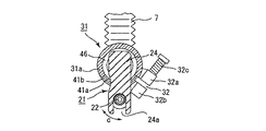
【0024】
偏心保持体10は、2個のL型部材21と、中空の車軸(下方の軸)22とで構成されている。車軸22には、前輪6のハブ6aがボールベアリング(図示せず)を介して支持されており、前輪6は車軸22に対して軸回り(図4に示す矢印C方向)に回転自在の状態となっている。L型部材21は、軸部(上方の軸)23と平板状のアーム24とからなっている。アーム24の下端には溝24aが形成されており、車軸22はその両端が溝24aに嵌合固定されている。
なお、車軸(下方の軸)22と、軸部(上方の軸)23とは平行となっており、アーム24は、軸部23に対して直角となっている。ハブ6aはカム軸6bと調節ナット6cとによりアーム24に固定されている。一方、上下動サスペンションの緩衝部7の端部位置には、ハウジング31が形成されており、ハウジング31内には弾性体41及びL型部材21の軸部23が支持されている。
このL型部材21の軸部23を支持するハウジング31、弾性体41等が軸支部30を構成するものである。
【0025】
ハウジング31は、軸方向(図3における左右方向)に抜けた円筒形状を有している。また、ハウジング31は、すり割り32を備えており、締め付けが可能である。この締め付けは、すり割り32を挟んでハウジング31の外面に形成されたボス部32a、32bを六角穴付きボルト32cで締め付けることにより行われる。
【0026】
弾性体41は、円筒状のものであり、ゴムからなる厚肉の本体41aと、本体41aの両面に固着された薄肉で金属製の外面部材41b及び内面部材41cとからなる。本体41aは所定の角度範囲内での捻れを許容するものである。軸部23は、弾性体41の孔41dに嵌挿されており、キー42により弾性体41に対して軸回りに回転不能となっている。一方、弾性体41は、ハウジング31をすり割り32によって締め付けることにより、ハウジング31に対して回転不能、すなわち、軸回りに回転不能となっている。
なお、キー42は、断面凸状のものである。内面部材41cの内面には溝43aが形成されており、溝43aにはキー42の凸部42aが嵌合される。また、軸部23の外面には溝43bが形成されており、溝43bにはキー42の基部42bが嵌合される。
【0027】
44は、孔41dに嵌挿される円柱部44aを有する蓋である。蓋44は、円柱部44aが孔41dにL型部材21とは反対側から嵌挿され、軸部23にボルト45により固定されている。すなわち、L型部材21は、蓋44及び六角穴付きボルト45により弾性体41に対して軸方向移動不能に固定されている。46は、アーム24と弾性体41との間に配設された円環状の樹脂製の受け板である。L型部材21は、ハウジング31による弾性体41の固定状態を調節することにより、アーム24が鉛直に立った状態でハウジング31に支持され、軸部23が車軸22の鉛直上方に位置する。
48は、軸部23とは反対側からハウジング31を塞ぐカバーであり、カバー48の内周面には、ハウジング31の外面に嵌合するためのネジ(図示せず)が形成されている。なお、説明の便宜上、図5において、カバー48は図示していない。
【0028】
また、ハウジング31のL型部材21側には、ストッパ部31aが一体的に形成されており、図6に示すように、ストッパ部31aは、ハウジング31を厚肉として下側の円弧部分を所定の範囲Xだけ切り欠いて形成されている。
【0029】
このような構成の偏心保持体(前後動サスペンション)10において、L型部材21をハウジング31に支持させる組立ては以下のように行う(図6参照)。
まず、すり割り32を緩めた状態でハウジング31内に、弾性体41を収納させ、すり割りを締めて固定する。軸部23に受け板46を通し、さらに、軸部23の溝43bにキー42を嵌合させ、この軸部23を、キー42を溝43aに嵌合させながら孔41dに嵌挿させる。そして、蓋44をボルト45により軸部23に固定する。
【0030】
このような偏心保持体(前後動サスペンション)10では、自転車が平坦な路面を走行している際には、前輪6に対して真下からも前からも衝撃が加わることがないため、L型部材21はアーム24が鉛直に立ったままの状態を維持する。すなわち、偏心保持体(前後動サスペンション)10は平坦な路面を走行する際には衝撃緩和作用を発揮しない。従って、乗員がペダルを力一杯漕いでも車体が上下動することは殆どなく、乗員が力を充分に発揮することができる。
【0031】
一方、自転車が路面上の突起を乗り越える際には、前輪6には真下からも前からも衝撃が加わる。前輪6は、前からの衝撃を受けると、弾性体41の本体41aを捻りながら、軸部23と車軸22との軸間距離Y(図3参照)を半径とし軸部23を中心として、後方向に所定の角度だけ揺動する。このように揺動することにより、前からの衝撃は後方へ逃がされる。しかも、上述したように揺動することにより、前輪6は、上方へも移動しているので、真下からの衝撃は上方へ逃がされる。このように偏心保持体(前後動サスペンション)10によれば、前輪6に加わる前方からの衝撃や真下からの衝撃を緩和することができる。
【0032】
次に、第1実施形態に係る前輪支持機構の制動装置について説明する。
図7は、図2に示した制動装置200の部分断面正面図である。図8は、図2に示した制動装置200の側面図である。
鉛直支持部材4の上端に設けられた制動装置200は、キャリパブレーキからなり、前輪6のタイヤ61の内周に設けられたリム62の側面(制動面)62aをブレーキシュー(制動部材)63により挟圧することにより、制動を行うようになっている。
【0033】
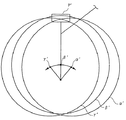
図9は、第1実施形態に係る前輪支持機構における前輪の移動範囲と制動位置との関係を示す概略図である。
αは、前輪が後方へ円運動した際の車軸及び前輪の位置を示している。βは、衝撃や振動が加わっていない状態における車軸及び前輪の位置を示している。γは、前輪が前方へ円運動した際の車軸及び前輪の位置を示している。
このように、第1実施形態に係る前輪支持機構では、上述したような偏心保持体(前後動サスペンション)10の作用によって、前輪が前後方向へ円運動をすることとなるが、前輪の移動距離が最も短い部分は、図9に示すように、前輪の車軸の鉛直上方に位置する部分Pとなる。第1実施形態に係る前輪支持機構では、鉛直支持部材の上部、すなわち、上記車軸の鉛直上方に位置する部分Pに、制動装置が設けられているため、図8に示したリム62の側面(制動面)62aを広くしたり、ブレーキシュー(制動部材)63の形状を調整したりするというように、専用品を製造する必要がなく、従来から用いられている車軸や制動装置を用いることができ、製造コストを低減することができる。
【0034】
[第2実施形態]
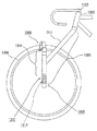
図10は、第2実施形態に係る前輪支持機構を備えた自転車を模式的に示す全体側面略図である。
自転車のフロントフォーク305には、前輪306を支持する懸架装置400が設けられている。この懸架装置400は、前輪306に対する上下方向の振動を緩衝する上下動サスペンション450と、上下動サスペンション450の下端位置に設けられた偏心保持体(前後動サスペンション)310とを備えている。偏心保持体310は、前輪306に対する前後方向の振動を緩衝するものである。また、上下動サスペンション450の上部には、前輪306を制動する制動装置500が設けられている。
【0035】
図11は、第2実施形態に係る前輪支持機構を模式的に示す側面図である。
フロントフォーク305に設けられた懸架装置400は、上下動サスペンション450と、偏心保持体310とを備えている。上下動サスペンション450は、前輪306に対して上下方向に設けられた鉛直支持部材(剛性部)304と、鉛直支持部材304に対して上下方向に摺動自在に設けられた緩衝部307と、緩衝部307の端部位置に設けられた軸支部330とを有するものである。緩衝部307は、ベローズ内にコイルスプリングと油圧ダンパとが設けられて構成される。また、上下動サスペンション450の上部には、キャリパブレーキからなる制動装置500が設けられている。
【0036】
また、第1実施形態と同様に、フロントフォーク305の上端側には、円筒形状のヘッドパイプ303が設けられ、ヘッドパイプ303には、ハンドルを備えたハンドル支柱302が差し込まれ、ハンドル支柱302の芯線を中心にハンドルが旋回可能となるように連結されている。また、図中に示すように、ハンドル支柱302は、その芯線の下側を進行方向側へ向けて傾斜するように設けられている。なお、この傾斜角度(キャスタ角)については、第1実施形態と同様であるので、ここでの説明は省略する。
【0037】
第2実施形態に係る前輪支持機構では、上下動サスペンション450の緩衝部307が上下方向に設けられているため、すべり摩擦を防止することが可能であり、上下方向の衝撃や振動に対する緩衝性能が低下することがなく、充分に緩衝性能を発揮することができる。
【0038】
次に、第2実施形態に係る前輪支持機構の前後動サスペンションについて説明する。
図12は、図11に示した偏心保持体(前後動サスペンション)310のIV−IV線断面図であり、図13は、図12のV−V線断面図である。
【0039】
偏心保持体310は、2個のL型部材321と、中空の車軸(上方の軸)322とで構成されている。車軸322には、前輪306のハブ306aがボールベアリング(図示せず)を介して支持されており、前輪306は車軸322に対して軸回り(図13に示す矢印D方向)に回転自在の状態となっている。L型部材321は、軸部(下方の軸)323と平板状のアーム324とからなっている。アーム324の上端部には孔324aが形成されており、車軸322はその両端が孔324aに嵌合固定されている。
【0040】
なお、車軸(上方の軸)322と、軸部(下方の軸)323とは平行となっており、アーム324は、軸部323に対して直角となっている。ハブ306aはカム軸306bと調節ナット306cとによりアーム324に固定されている。一方、上下動サスペンションの緩衝部307の端部位置には、ハウジング31が形成されており、ハウジング31内には、ベアリング332、333によりL型部材321の軸部323が支持されている。このL型部材321の軸部323を支持するハウジング331、ベアリング332、333等が軸支部330を構成するものである。
【0041】
ハウジング331は、軸方向(図12における左右方向)に抜けた略円筒形状を有しており、ボールベアリング332、333を介して、L型部材321の軸部323が回転自在に支持されている。ボールベアリング333の外周面側には、Oリング334が配設されている。さらに、軸部323の先端には、ボルト336によってロータ335が固定されている。
338は、軸部323とは反対側からハウジング331を塞ぐカバーであり、カバー338の内周面には、ハウジング331の外面に嵌合するためのネジ(図示せず)が形成されている。
【0042】
ハウジング331内において、ロータ335とカバー338との間には、室337が形成され、この室337内には、例えば、シリコンオイル等の粘性流体が充填される。室337の軸部323側はOリング334によって封止され、粘性流体のボールベアリング333側への流出が防止される。軸部323の回転に伴って、その先端に固定されたロータ335が回転すると、室337に充填された粘性流体の粘性抵抗によって、ロータ335の回転に対して抵抗力を加えることができる。すなわち、緩衝部307(上下動サスペンション)と、偏心保持体310(前後動サスペンション)との間に、減衰機構が設けられているのである。
【0043】
図12、13に示した偏心保持体(前後動サスペンション)310では、自転車が平坦な路面を走行している際には、前輪306に対して真下からも前からも衝撃が加わることがないため、L型部材321は、車体及び乗員の自重により、アーム324が垂下した状態を維持する。すなわち、偏心保持体(前後動サスペンション)310は、平坦な路面を走行する際には衝撃緩和作用を発揮しない。従って、乗員がペダルを力一杯漕いでも車体が上下動することは殆どなく、乗員が力を充分に発揮することができる。
【0044】
一方、自転車が路面上の突起を乗り越える際には、前輪306には真下からも前からも衝撃が加わる。前輪306は、前からの衝撃を受けると、軸部323と車軸322との軸間距離Z(図13参照)を半径とし軸部323を中心として、後方向に所定の角度だけ揺動する。このように揺動することにより、前からの衝撃は後方へ逃がされる。しかも、上述したように揺動することにより、前輪306は、上下方向へも移動しているので、真下からの衝撃は上方へ逃がされる。このように偏心保持体(前後動サスペンション)310によれば、前輪306に加わる前方からの衝撃や真下からの衝撃を緩和することができる。
【0045】
本発明においては、上下動サスペンションと前後動サスペンションとの間に減衰機構が設けられていることが望ましい。自励振動や共振等の予期しない不都合な振動を防止することができ、操作性を向上させるとともに安全性を高めることができるからである。
【0046】
また、減衰機構は、図12に示すように、軸部323の回転に対して抵抗力を加えることが可能な回転減衰機構であることが望ましい。軸部323の回転に対して抵抗力を加えることにより、自励振動や共振等の不都合な振動の発生を防止することができ、操作性を向上させるとともに安全性を高めることができるからである。
【0047】
なお、図12に示したハウジング331内の室337に充填される粘性流体は、特に限定されるものではなく、回転減衰機構に用いられる従来公知の粘性流体を用いることができる。また、粘性流体に代えて、例えば、シリコンオイル等を混入させた樹脂板を成形し、室337に配設することも可能である。さらに、粘性流体を利用せずに、ロータ335とカバー338とを直接接触させて摩擦抵抗によってロータ335の回転に対して抵抗力を加えることとしてもよい。このようにする場合、ロータ335及び/又はカバー338を、例えばシリコンオイル等を混入させた樹脂を用いて成形してもよく、また、摩擦力を高めるために、ステアリン酸やオレイン酸アミド等のスリップ剤を混入させてもよい。
【0048】
また、前輪支持機構に適用可能な回転減衰機構としては、粘性流体を利用したものに限定されず、例えば、フロントフォーク側と偏心保持体側とに、それぞれ対向するように永久磁石を固定し、永久磁石の吸着力と反発力とを利用して、軸部323の回転に抵抗力を加える回転減衰機構や、オリフィスを利用した回転減衰機構等を挙げることができる。勿論、このような回転減衰機構は、第1実施形態に係る前輪支持機構にも適用可能することが可能である。
【0049】
また、第2実施形態に係る前輪支持機構の制動装置500は、第1実施形態に係る前輪支持機構の制動装置100と同様の構成を有しており、既に説明済であるので、ここでの説明は省略する。次に、前輪の移動範囲と制動位置との関係について説明する。
図14は、第2実施形態に係る前輪支持機構における前輪の移動範囲と制動位置との関係を示す概略図である。
α′は、前輪が後方へ円運動した際の車軸及び前輪の位置を示している。β′は、衝撃や振動が加わっていない状態における車軸及び前輪の位置を示している。γ′は、前輪が前方へ円運動した際の車軸及び前輪の位置を示している。
このように、第2実施形態に係る前輪支持機構では、上述したような偏心保持体(前後動サスペンション)310の作用によって、前輪が前後方向へ円運動することとなるが、前輪の移動距離が最も短い部分は、図14に示すように、前輪の車軸の鉛直上方に位置する部分P′となる。第2実施形態に係る前輪支持機構では、鉛直支持部材の上部、すなわち、上記車軸の鉛直上方に位置する部分P′に、制動装置が設けられているため、制動面を広くしたり、制動装置の制動部材の形状を調整したりするというように、専用品を製造する必要がなく、従来から用いられている車軸や制動装置を用いることができ、製造コストを低減することができる。
【0050】
以上、第1、2実施形態について説明したが、さらに、本発明の前輪支持機構においては、以下のような構成を採用することが可能である。
(A)第1、2実施形態に係る前輪支持機構では、偏心保持体が、クランク軸構造を有していたが、本発明の前輪支持機構に係る偏心保持体は、偏心円筒であってもよい。
【0051】
(B)第2実施形態に係る前輪支持機構では、図12に示すように、ハウジング331内に、ボールベアリング332、333を介して、軸部323が回転自在に支持されているが、第1実施形態に係る前輪支持機構のように、弾性体を介して軸部が回転可能に支持されるようにしてもよい。
また、本発明の前輪支持機構においては、弾性体とベアリングとが並列に配設され、弾性体及びベアリングを介して軸部が回転可能に支持されるようにすることが可能である。このようにした場合、剛性を高め、共振や自励振動等の不都合な振動の発生を抑制することができる。
【0052】
図15は、本発明の前輪支持機構の他の実施形態に係る前後動サスペンションを模式的に示す断面図である。
前後動サスペンションである偏心保持体610は、2個のL型部材621と、中空の車軸(下方の軸)622とで構成されている。車軸622には、前輪のハブ606aがボールベアリング(図示せず)を介して支持されており、前輪は車軸622に対して軸回りに回転自在の状態となっている。L型部材621は、軸部(上方の軸)623と平板状のアーム624とからなっている。アーム624の下端には孔624aが形成されており、車軸622はその両端が孔624aに嵌合固定されている。
なお、車軸(下方の軸)622と、軸部(上方の軸)623と平行となっており、アーム624は、軸部623に対して直角となっている。ハブ606aはカム軸606bと調節ナット606cとによりアーム624に固定されている。
【0053】
上下動サスペンションの緩衝部607の下端側には、ハウジング631が形成されている。ハウジング631は、軸方向(図15における左右方向)に抜けた円筒形状を有しており、ハウジング631の中央部分には、弾性体641が設けられている。
弾性体641は、円筒状のものであり、ゴムからなる厚肉の本体と、本体の両面に固着された薄肉で金属製の外面部材及び内面部材とからなるものである。本体は、所定の角度範囲内での捻れを許容するものである。また、弾性体641の左右の両側には、ベアリング632、633が設けられている。
【0054】
軸部623は、ベアリング632、633及び弾性体641に嵌合され、さらに、キー(図示せず)により弾性体641に対して軸回りに回転不能となるように支持される。638は、軸部623とは反対側からハウジング631を塞ぐカバーであり、このカバー638の内周面には、ハウジング631の外面に嵌合するためのネジが形成されている。また、軸部623の先端側には、蓋635がボルト636によって固定されている。すなわち、L型部材621は、蓋638及びボルト636により弾性体641に対して軸方向移動不能に固定されている。
【0055】
図15に示すように、ベアリング632、633と弾性体641とを併用して軸部(上方の軸)623を支持することにより、剛性を高め、弾性体641の軸方向(図15における左右方向)への捻れを防止することができるため、共振や自励振動等の不都合な振動の発生を防止することができる。また、このような構成は、第2実施形態のように、軸部が車軸の下側に位置する場合であっても、採用することが可能である。
【0056】
また、本発明は、以下のようなものを提供する。
(I)二輪車のフロントフォーク(例えば、フロントフォーク1005)に取り付けられて前輪(例えば、前輪1006)を支持する懸架装置(例えば、懸架装置1100)を備えた二輪車前輪支持機構であって、
上記懸架装置は、2つの平行な軸を有する偏心保持体(例えば、偏心保持体1010)の下方の軸を上記前輪の車軸(例えば、車軸1022)とし、この軸の回りに上記前輪を回転自在に支持するとともに、上方の軸(例えば、軸部1023)を上記車軸の鉛直上方に位置するように弾性体(例えば、弾性体1041)を介して、上記フロントフォークに対して回転可能に支持することにより、上記前輪に上記車軸の軸線まわりの回転運動と、上記偏心保持体の2つの平行な軸間距離を半径とする前後円運動とを可能とするものであり、
上記フロントフォークは、上記懸架装置を介して上記前輪の車軸から鉛直方向に設けられた鉛直支持部材(例えば、鉛直支持部材1004)を備えるとともに、上記鉛直支持部材には上下懸架装置(例えば、上下懸架装置1007)が設けられていることを特徴とする二輪車前輪支持機構(図16参照)。
【0057】
(I)の発明によれば、前輪が路面の突起等を乗り越える際に、懸架装置の作用によって前輪を前後円運動させ、前輪を後回りに回動させるとともに、上方へも移動させることができるため、前輪に加わる前方からの衝撃や真下からの衝撃を緩和することができる。
【0058】
また、フロントフォークを構成する鉛直支持部材には、上下懸架装置が設けられているため、上下方向の振動や衝撃を緩和することができる。
従来の二輪車前輪支持機構では、通常、フロントフォークに設けられる上下懸架装置は斜め方向に向いており、重力によって上下懸架装置の可動部分に対して斜めに荷重が掛かり、当該可動部分がフロントフォーク等と接触してしまうため、充分に緩衝性能を発揮することができなかったが、(I)の発明においては、上下懸架装置が鉛直方向に設けられているため、上下方向の振動や衝撃に対して充分な緩衝性能を発揮することができる。
【0059】
このように、上記懸架装置により、前輪に加わる前方からの衝撃や真下からの衝撃を緩和するとともに、鉛直方向に設けられた上下懸架装置により、上下方向の振動や衝撃に対して充分な緩衝性能を発揮することができるため、衝撃や振動による疲労を軽減して乗り心地を改善することができ、さらに、前進抵抗力を軽減してさらなる高速化を図ることができるとともに、スリップを防止することができ、スリップ等に伴うタイヤの粉塵公害を防止することも可能になる。
【0060】
本発明は、さらに以下のようなものを提供する。
(II)二輪車のフロントフォーク(例えば、フロントフォーク1305)に取り付けられて前輪(例えば、前輪1306)を支持する懸架装置(例えば、懸架装置1400)を備えた二輪車前輪支持機構であって、
上記懸架装置は、2つの平行な軸を有する偏心保持体(例えば、偏心保持体1310)の上方の軸を上記前輪の車軸(例えば、車軸1322)とし、この軸の回りに上記前輪を回転自在に支持するとともに、下方の軸(例えば、軸部1323)を上記フロントフォークに対して回転自在に支持することにより、上記前輪に上記前輪の車軸まわりの回転運動と、上記偏心保持体の2つの平行な軸間距離を半径とする前後円運動とを可能とするものであり、
上記フロントフォークは、前記下方の軸から鉛直上方に延びた鉛直支持部材(例えば、鉛直支持部材1305)を備えるとともに、上記鉛直支持部材には上下懸架装置(例えば、上下懸架装置1307)が設けられていることを特徴とする二輪車前輪支持機構(図17、18参照)。
【0061】
(II)の発明によれば、上記(I)の発明と同様に、前輪に加わる前方からの衝撃や真下からの衝撃を緩和するとともに、鉛直方向に設けられた上下懸架装置により、上下方向の振動や衝撃に対して充分な緩衝性能を発揮することができるため、衝撃や振動による疲労を軽減して乗り心地を改善することができ、さらに、前進抵抗力を軽減してさらなる高速化を図ることができるとともに、スリップを防止することができ、スリップ等に伴うタイヤの粉塵公害を防止することも可能になる。
【0062】
本発明は、さらに以下のようなものを提供する。
(III) 上記(I)又は(II)に記載の二輪車前輪支持機構であって、
上記鉛直支持部材の上部には、前輪を制動する制動装置(例えば、制動装置1200)が設けられ、
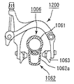
上記制動装置は、前輪に設けられた制動面(例えば、リムの側面1062a)を、上記鉛直支持部材に設けられた制動部材(例えば、ブレーキシュー1063)により押圧して制動を行うものであることを特徴とする(図19参照)。
【0063】
上記(I)又は(II)に記載の二輪車前輪支持機構においては、上記前輪が上記偏心保持体の2つの平行な軸間距離を半径とする前後円運動するため、前輪が所定範囲で移動することとなるが、このような懸架装置の作用による前輪の移動距離が最も短い部分は、前輪の車軸の直上方向に位置する部分となる。
(III)の発明によれば、鉛直支持部材の上部、すなわち、懸架装置の作用による前輪の移動距離が最も短い部分である車軸の直上方向に、制動装置が設けられているため、例えば、前輪の制動面(例えば、前輪のリムの側面等)の幅を広くしたり、制動装置の制動部材(例えば、前輪のブレーキシュー等)の形状を調整したりするというように専用品を製造することなく、従来から用いられている車輪や制動装置を用いることができ、製造コストを低減することができる。
【0064】
本発明は、さらに以下のようなものを提供する。
(IV)上記(I)〜(III)のいずれか1に記載の二輪車前輪支持機構であって、
上記フロントフォーク(例えば、フロントフォーク1305)と上記偏心保持体(例えば、偏心保持体1310)との間には、回転減衰機構が設けられていることを特徴とする(図18参照)。
【0065】
上記(I)〜(III)に記載の二輪車前輪支持機構においては、懸架装置の作用により前輪が回転運動するとともに前後円運動し、さらに、上下懸架装置の作用により上下運動するため、ハンドル操作による運動もあわせると、前輪は他方向へ同時に運動することになり、例えば、自励振動等、予期しないような不都合な振動が発生するおそれがある。しかしながら、(IV)の発明によれば、フロントフォークと偏心保持体との間に回転減衰機構が設けられているため、このような不都合な振動の発生を防止することができ、操作性を向上させるとともに安全性を高めることができる。
【0066】
図16は、本発明に係る二輪車前輪支持機構の実施形態を模式的に示す側面図である。
フロントフォーク1005は、上述した鉛直支持部材1004と、その側面に後上方へ向けて設けられた斜支持部材1011とから構成される。鉛直支持部材1004は、その下端側に、ベローズ内にコイルスプリングと油圧ダンパとを有する上下懸架装置1007を備えており、上下方向の衝撃や振動を緩衝し軽減することができる。また、鉛直支持部材1004には、その上端側に、キャリパブレーキからなる制動装置1200が設けられている。
【0067】
一方、鉛直支持部材1004の下端には、弾性体1041を備えた偏心保持体1010からなる懸架装置1100が設けられ、懸架装置1100により前輪1006の車軸が支持される。
【0068】
また、フロントフォーク1005の上端側には、円筒形状のヘッドパイプ1003が設けられ、ヘッドパイプ1003には、ハンドルを備えたハンドル支柱1002が差し込まれている。このハンドル支柱1002は、引上ボルト(図示せず)の先に付いた臼のくさび作用によって、ハンドル支柱1002の芯線を中心にハンドルが旋回可能となるように、ヘッドパイプ1003に連結されている。また、図中に示すように、ハンドル支柱1002は、その芯線の下側を進行方向側へ向けて傾斜するように設けられている。
【0069】
図17は、本発明に係る二輪車前輪支持機構の実施形態を模式的に示す側面図である。
自転車のフロントフォーク1305は、懸架装置1400を介して前輪1306を回転自在に支持しており、懸架装置1400から鉛直上方へ延びた鉛直支持部材1304を備えている。また、鉛直支持部材1304の上部には、前輪1306を制動する制動装置1500が設けられている。
フロントフォーク1305は、上述した鉛直支持部材1304と、その側面に後上方へ向けて設けられた斜支持部材1311とから構成される。鉛直支持部材1304は、その下端側に、ベローズ内にコイルスプリングと油圧ダンパとを有する上下懸架装置1307を備えており、上下方向の衝撃や振動を緩衝し軽減することができる。また、鉛直支持部材1304には、その上端側に、キャリパブレーキからなる制動装置1500が設けられている。
【0070】
また、フロントフォーク1305の上端側には、円筒形状のヘッドパイプ1303が設けられ、ヘッドパイプ1303には、ハンドルを備えたハンドル支柱1302が差し込まれ、ハンドル支柱1302の芯線を中心にハンドルが旋回可能となるように連結されている。また、図中に示すように、ハンドル支柱1302は、その芯線の下側を進行方向側へ向けて傾斜するように設けられている。
【0071】
図18は、本発明に係る二輪車前輪支持機構の実施形態を模式的に示す断面図である。
偏心保持体1310は、2個のL型部材1321と、中空の車軸(上方の軸)1322とで構成されている。車軸1322には、前輪1306のハブ1306aがボールベアリング(図示せず)を介して支持されており、前輪1306は車軸1322に対して軸回りに回転自在の状態となっている。L型部材1321は、軸部(下方の軸)1323と平板状のアーム1324とからなっている。アーム1324の上端部には孔1324aが形成されており、車軸1322はその両端が孔1324aに嵌合固定されている。
なお、車軸(上方の軸)1322と、軸部(下方の軸)1323とは平行となっており、アーム1324は、軸部1323に対して直角となっている。ハブ1306aはカム軸1306bと調節ナット1306cとによりアーム1324に固定されている。一方、鉛直支持部材1304に設けられた上下懸架装置1307の下端には、ハウジング1331が形成されている。
【0072】
ハウジング1331は、軸方向(図18における左右方向)に抜けた略円筒形状を有しており、ボールベアリング1332、1333を介して、L型部材1321の軸部1323が回転自在に支持されている。ボールベアリング1333の外周面側には、Oリング1334が配設されている。さらに、軸部1323の先端には、ボルト1336によってロータ1335が固定されている。
1338は、軸部1323とは反対側からハウジング1331を塞ぐカバーであり、カバー1338の内周面には、ハウジング1331の外面に嵌合するためのネジ(図示せず)が形成されている。
【0073】
ハウジング1331内において、ロータ1335とカバー1338との間には、室1337が形成され、この室1337内には、例えば、シリコンオイル等の粘性流体が充填される。室1337の軸部1323側はOリング1334によって封止され、粘性流体のボールベアリング1333側への流出が防止される。軸部1323の回転に伴って、その先端に固定されたロータ1335が回転すると、室1337に充填された粘性流体の粘性抵抗によって、ロータ1335の回転に対して抵抗力を加えることができる。すなわち、鉛直支持部材1304(フロントフォーク1305)と、偏心保持体1310との間のハウジング1331内に、回転減衰機構が設けられているのである。
【0074】
図19は、本発明に係る二輪車前輪支持機構の実施形態に係る制動装置を模式的に示す断面図である。
鉛直支持部材1004の上端に設けられた制動装置1200は、キャリパブレーキからなり、前輪1006のタイヤ1061の内周に設けられたリム1062の側面(制動面)1062aをブレーキシュー(制動部材)1063により挟圧することにより、制動を行うようになっている。
【0075】
【発明の効果】
本発明によれば、前後動サスペンションによって前輪に加わる前方からの衝撃を緩和することができるとともに、上下動サスペンションによって前輪に加わる真下からの衝撃を緩和することができるため、衝撃や振動による疲労を軽減して乗り心地を改善することができる。
【0076】
さらに、前進抵抗力を軽減してさらなる高速化を図ることができるとともに、スリップを防止することができ、スリップ等に伴うタイヤの粉塵公害を防止することも可能になる。
【0077】
また、本発明によれば、上下動サスペンションが、前輪に対して上下方向に設けられた剛性部と、剛性部に対して上下方向に摺動可能な緩衝部と、緩衝部の端部位置に設けられた軸支部とを有する構成とすると、緩衝部が剛性部に対して上下方向に摺動自在に設けられているため、すべり摩擦を防止することが可能であり、上下方向の振動や衝撃に対して充分な緩衝性能を発揮することができる。
【0078】
また、本発明によれば、前後動サスペンションの一端部を軸支部に対して揺動自在に設けられるとともに、他端部を前輪の車軸に対して回動自在に支持する構成とすると、前輪に衝撃が加わったとき、上記一端部を中心として、前輪を後方へ円運動させて逃がすことができるため、前後方向の衝撃や振動に対する緩衝性能と、上下方向の衝撃や振動に対する緩衝性能とをさらに向上させることができる。
【0079】
また、本発明によれば、上下動サスペンションの上部に制動装置が設けられる構成とすると、懸架装置の作用による前輪の移動距離が最も短い部分である車軸の直上方向に、制動装置が設けられているため、例えば、前輪の制動面の幅を広くしたり、制動装置の制動部材の形状を調整したりするというように専用品を製造することなく、従来から用いられている車輪や制動装置を用いることができ、製造コストを低減することができる。
【0080】
さらに、本発明によれば、上下動サスペンションと前後動サスペンションとの間に減衰機構が設けられた構成とすると、懸架装置の作用やハンドル操作等の多方向への運動に伴って発生するおそれがある自励振動や共振等の予期しない不都合な振動を防止することができ、操作性を向上させるとともに安全性を高めることができる。
【図面の簡単な説明】
【図1】第1実施形態に係る前輪支持機構を備えた自転車を模式的に示す全体側面略図である。
【図2】第1実施形態に係る前輪支持機構を模式的に示す側面図である。
【図3】図2に示した偏心保持体(前後動サスペンション)10のI−I線断面図である。
【図4】図3のII−II線断面図である。
【図5】図3のIII矢視図である。
【図6】図2に示した偏心保持体(前後動サスペンション)10の分解斜視図である。
【図7】図2に示した制動装置200の部分断面正面図である。
【図8】図2に示した制動装置200の側面図である。
【図9】第1実施形態に係る前輪支持機構における前輪の移動範囲と制動位置との関係を示す概略図である。
【図10】第2実施形態に係る前輪支持機構を備えた自転車を模式的に示す全体側面略図である。
【図11】第2実施形態に係る前輪支持機構を模式的に示す側面図である。
【図12】図11に示した偏心保持体(前後動サスペンション)310のIV−IV線断面図である。
【図13】図12のV−V線断面図である。
【図14】第2実施形態に係る前輪支持機構における前輪の移動範囲と制動位置との関係を示す概略図である。
【図15】本発明の前輪支持機構の他の実施形態に係る偏心保持体(前後動サスペンション)を模式的に示す断面図である。
【図16】本発明に係る二輪車前輪支持機構の実施形態を模式的に示す側面図である。
【図17】本発明に係る二輪車前輪支持機構の実施形態を模式的に示す側面図である。
【図18】本発明に係る二輪車前輪支持機構の実施形態を模式的に示す断面図である。
【図19】本発明に係る二輪車前輪支持機構の実施形態に係る制動装置を模式的に示す断面図である。
【符号の説明】
2、302 ハンドル支柱
3、303 ヘッドパイプ
4、304、604 鉛直支持部材
5、305 フロントフォーク
6、306 前輪
7、307、607 緩衝部
10、310、610 偏心保持体(前後動サスペンション)
22、322、622 車軸
23、323、623 軸部
62 リム
62a リムの側面(制動面)
63 ブレーキシュー(制動部材)
100、400 懸架装置
150、450 上下動サスペンション
200、500 制動装置[0001]
TECHNICAL FIELD OF THE INVENTION
The present invention relates to a front wheel support mechanism that is used in, for example, two-wheeled vehicles such as bicycles and motorcycles and that includes a suspension device.
[0002]
[Prior art]
For example, impacts and vibrations in the front-rear direction are generated on running wheels due to deformation of tires, small unevenness on a road surface, speed difference between front and rear wheels, and the like. The effect of the front-rear force increases as the road surface becomes worse and the vehicle speed increases, but the conventional suspension system has sufficient shock-absorbing performance against such front-rear shocks and vibrations due to high speed. Did not have. In order to solve such a problem, the present inventor has proposed a suspension device having an eccentric holding member that incorporates a circular motion in the front-rear direction on wheels (for example, see Patent Documents 1 to 3). According to the suspensions described in Patent Literatures 1 and 2, it is possible to exhibit sufficient shock absorbing performance against impact and vibration in the front-rear direction, and according to the suspension described in
[0003]
[Patent Document 1]
JP-B-49-17161
[Patent Document 2]
Japanese Patent Publication No. 50-13521
[Patent Document 3]
Japanese Patent No. 2524908
[0004]
[Problems to be solved by the invention]
By the way, in recent years, a wave of speeding up has been rushing also in the bicycle world. This is no exception in everyday bicycles. In other words, with the development of ultra-lightweight car bodies, thin and high-pressure tires, and the development of multi-stage transmissions, it has become possible to run bicycles at the same speed as small motorcycles. The impact and vibration applied to the vehicle body when traveling on an uneven road surface or the like become extremely large. When the impact or vibration applied to the vehicle body during traveling increases, not only does riding comfort deteriorate, causing occupants to fatigue, but also the forward resistance increases and the speed decreases. There is also a risk of causing tire dust pollution. Such a problem occurs not only in bicycles but also in motorcycles and tricycles including motorcycles. Each of the suspensions of Patent Documents 1 to 3 can exhibit sufficient shock-absorbing performance against shocks and vibrations in the front-back direction. Considering the increase in shock and vibration during traveling due to the above, there is still room for improvement.
[0005]
SUMMARY OF THE INVENTION The present invention has been made in view of the above-described problems, and has as its object not only a shock absorbing function against shocks and vibrations in the front-rear direction, but also a sufficient function of damping shocks and vibrations in the vertical direction. It is possible to improve the ride comfort by reducing the fatigue due to shock and vibration, and to further reduce the forward resistance to further increase the speed, and to prevent the slip, etc. It is an object of the present invention to provide a front wheel support mechanism capable of preventing dust pollution of a tire accompanying the above.
[0006]
[Means for Solving the Problems]
In order to solve the above-described problems, the present invention provides the following.
(1) A front wheel support mechanism provided on a front fork (for example, front fork 5) of a front wheel (for example, front wheel 6) and supporting a suspension device that supports the front wheel,
A vertically moving suspension (for example, a vertically moving suspension 150) which is provided integrally with the front fork and buffers vibration in a vertical direction with respect to the front wheel;
A front-wheel support mechanism (FIG. 2) which includes a front-rear suspension (for example, an eccentric holding body 10) that is swingably provided at a lower end position of the vertical suspension and buffers vibration in the front-rear direction with respect to the front wheel. 3).
[0007]
According to the invention of (1), the impact from the front applied to the front wheels can be reduced by the front-rear suspension, and the impact from just below applied to the front wheels can be alleviated by the up-down suspension. And the ride comfort can be improved.
[0008]
Furthermore, the forward resistance can be reduced to further increase the speed, and the slip can be prevented, and the dust pollution of the tire due to the slip or the like can be prevented.
[0009]
(2) The front wheel support mechanism according to (1),
The vertical movement suspension (for example, the vertical movement suspension 150) is provided with a rigid portion (for example, the vertical support member 4) provided in the vertical direction with respect to the front wheel, and is slidable in the vertical direction with respect to the rigid portion. It is characterized by having a provided buffer portion (for example, the buffer portion 7) and a pivot portion (for example, the pivot portion 30) provided at an end position of the buffer portion (see FIG. 2).
[0010]
According to the invention of (2), since the shock-absorbing portion is provided so as to be slidable in the vertical direction with respect to the rigid portion, it is possible to prevent sliding friction and to prevent vibration and impact in the vertical direction. Sufficient buffer performance can be exhibited.
[0011]
(3) The front wheel support mechanism according to (2),
The front-rear suspension (e.g., the eccentric support 10) has one end (e.g., the shaft portion 23) provided to be swingable with respect to the shaft support portion, and the other end of the suspension (e.g., the axle of the front wheel). 22) is rotatably supported (see FIG. 3).
[0012]
According to the invention of (3), when an impact is applied to the front wheel, the front wheel can be caused to escape by making a circular motion backward around the above-mentioned one end, so that the shock absorbing performance against shock and vibration in the front-rear direction and the vertical It is possible to further improve the shock absorbing performance against impact and vibration in the direction.
[0013]
(4) The front wheel support mechanism according to any one of (1) to (3),
A braking device (for example, a braking device 200) for braking a front wheel (for example, the front wheel 6) is provided on an upper part of the vertical suspension.
The braking device is characterized in that a braking surface (for example, a
[0014]
According to the invention of (4), since the braking device is provided immediately above the axle, which is the portion where the moving distance of the front wheel by the action of the suspension device is the shortest, for example, the braking surface of the front wheel (for example, the front wheel It is conventionally used without manufacturing a dedicated product such as widening the width of a rim or the like or adjusting the shape of a braking member of a braking device (for example, a brake shoe of a front wheel). Wheels and braking devices can be used, and manufacturing costs can be reduced.
[0015]
(5) The front wheel support mechanism according to any one of (1) to (4),
A damping mechanism is provided between the vertical movement suspension and the front-rear movement suspension.
[0016]
According to the invention of (5), unexpected inconvenient vibrations such as self-excited vibrations and resonances which may be generated due to the operation of the suspension device and the movement in multiple directions such as the operation of the steering wheel can be prevented. Operability can be improved and safety can be improved.
[0017]
BEST MODE FOR CARRYING OUT THE INVENTION
[First Embodiment]
A first embodiment of a front wheel support mechanism of the present invention will be described with reference to the drawings.
Hereinafter, a case where the present invention is applied to a bicycle will be described as a preferred embodiment of the front wheel support mechanism according to the present invention.
[0018]
FIG. 1 is a schematic overall side view schematically showing a bicycle provided with a front wheel support mechanism according to the first embodiment.
The front fork 5 of the bicycle is provided with a
[0019]
FIG. 2 is a side view schematically showing the front wheel support mechanism according to the first embodiment.
The
[0020]
A
[0021]
In the front wheel supporting mechanism according to the first embodiment, since the
[0022]
Further, in the front wheel support mechanism according to the first embodiment, the handle post 2 is provided so that the lower side of the core wire is inclined toward the traveling direction, so that the operability does not decrease. In addition, the inclination angle of the handle support 2, that is, the angle (caster angle) between the core wire of the handle support 2 and the horizontal plane (front wheel ground surface) is 60 to 75 ° from the viewpoint of ensuring the operability of the handle. , And more preferably 66 to 74 °.
[0023]
Next, a front-rear movement suspension of the front wheel support mechanism according to the first embodiment will be described.
FIG. 3 is a cross-sectional view taken along line II of the eccentric holding body (forward and backward moving suspension) 10 shown in FIG. 2, FIG. 4 is a cross-sectional view taken along line II-II of FIG. 3, and FIG. FIG. FIG. 6 is an exploded perspective view of the eccentric support (forward and backward moving suspension) 10 shown in FIG.
[0024]
The
The axle (lower shaft) 22 and the shaft (upper shaft) 23 are parallel to each other, and the
The
[0025]
The
[0026]
The
The key 42 has a convex cross section. A
[0027]
[0028]
A
[0029]
In the eccentric holding body (fore-and-aft movement suspension) 10 having such a configuration, the assembly for supporting the L-shaped
First, the
[0030]
With such an eccentric support (forward and backward movement suspension) 10, when the bicycle is traveling on a flat road surface, no impact is applied to the
[0031]
On the other hand, when the bicycle gets over the protrusion on the road surface, the
[0032]
Next, a braking device for a front wheel support mechanism according to the first embodiment will be described.
FIG. 7 is a partial cross-sectional front view of the
The
[0033]
FIG. 9 is a schematic diagram showing the relationship between the range of movement of the front wheels and the braking position in the front wheel support mechanism according to the first embodiment.
α indicates the positions of the axle and the front wheel when the front wheel makes a circular motion backward. β indicates the positions of the axle and the front wheel in a state where no impact or vibration is applied. γ indicates the positions of the axle and the front wheel when the front wheel makes a forward circular motion.
As described above, in the front wheel support mechanism according to the first embodiment, the front wheel makes a circular motion in the front-rear direction due to the action of the eccentric holding body (front-rear suspension) 10 as described above. Is the portion P located vertically above the axle of the front wheel, as shown in FIG. In the front wheel support mechanism according to the first embodiment, since the braking device is provided on the upper portion of the vertical support member, that is, on the portion P located vertically above the axle, the side surface of the
[0034]
[Second embodiment]
FIG. 10 is a schematic overall side view schematically showing a bicycle provided with a front wheel support mechanism according to the second embodiment.
A
[0035]
FIG. 11 is a side view schematically showing a front wheel support mechanism according to the second embodiment.
The
[0036]
Further, similarly to the first embodiment, a
[0037]
In the front wheel support mechanism according to the second embodiment, since the
[0038]
Next, a front-rear movement suspension of the front wheel support mechanism according to the second embodiment will be described.
FIG. 12 is a cross-sectional view taken along line IV-IV of the eccentric retainer (forward-backward movement suspension) 310 shown in FIG. 11, and FIG. 13 is a cross-sectional view taken along line VV in FIG.
[0039]
The
[0040]
The axle (upper shaft) 322 and the shaft (lower shaft) 323 are parallel to each other, and the
[0041]
The
[0042]
In the
[0043]
In the eccentric holder (forward and backward movement suspension) 310 shown in FIGS. 12 and 13, the impact is not applied to the
[0044]
On the other hand, when the bicycle rides over the protrusion on the road surface, an impact is applied to the
[0045]
In the present invention, it is desirable that a damping mechanism be provided between the up-down movement suspension and the back-and-forth movement suspension. This is because unexpected undesired vibrations such as self-excited vibration and resonance can be prevented, and operability and safety can be improved.
[0046]
As shown in FIG. 12, the damping mechanism is preferably a rotation damping mechanism that can apply a resistance to the rotation of the
[0047]
The viscous fluid filled in the
[0048]
Further, the rotation damping mechanism applicable to the front wheel supporting mechanism is not limited to a mechanism using a viscous fluid, and for example, a permanent magnet is fixed to the front fork side and the eccentric holder side so as to face each other, A rotation damping mechanism that applies a resisting force to the rotation of the
[0049]
Further, the
FIG. 14 is a schematic diagram illustrating the relationship between the movement range of the front wheels and the braking position in the front wheel support mechanism according to the second embodiment.
α ′ indicates the positions of the axle and the front wheel when the front wheel makes a circular motion backward. β ′ indicates the positions of the axle and the front wheel when no impact or vibration is applied. γ ′ indicates the positions of the axle and the front wheel when the front wheel makes a forward circular motion.
As described above, in the front wheel support mechanism according to the second embodiment, the front wheel makes a circular motion in the front-rear direction by the action of the eccentric holding body (front-rear suspension) 310 as described above. The shortest portion is a portion P 'located vertically above the axle of the front wheel, as shown in FIG. In the front wheel support mechanism according to the second embodiment, since the braking device is provided at the upper part of the vertical support member, that is, at the portion P 'located vertically above the axle, the braking surface can be increased or the braking device can be increased. There is no need to manufacture a dedicated product such as adjusting the shape of the braking member, and a conventionally used axle or braking device can be used, and the manufacturing cost can be reduced.
[0050]
Although the first and second embodiments have been described above, the following configuration can be further adopted in the front wheel support mechanism of the present invention.
(A) In the front wheel supporting mechanism according to the first and second embodiments, the eccentric holding body has a crankshaft structure. However, the eccentric holding body according to the front wheel supporting mechanism of the present invention may be an eccentric cylinder. Good.
[0051]
(B) In the front wheel support mechanism according to the second embodiment, as shown in FIG. 12, a
Further, in the front wheel support mechanism of the present invention, the elastic body and the bearing are arranged in parallel, and the shaft can be rotatably supported via the elastic body and the bearing. In this case, rigidity can be increased, and occurrence of undesired vibration such as resonance and self-excited vibration can be suppressed.
[0052]
FIG. 15 is a cross-sectional view schematically showing a front-rear suspension according to another embodiment of the front wheel support mechanism of the present invention.
The
The axle (lower shaft) 622 and the shaft (upper shaft) 623 are parallel to each other, and the
[0053]
A
The
[0054]
The
[0055]
As shown in FIG. 15, by supporting the shaft (upper shaft) 623 using the
[0056]
Further, the present invention provides the following.
(I) A motorcycle front wheel support mechanism including a suspension device (for example, a suspension device 1100) attached to a front fork (for example, a front fork 1005) of a motorcycle and supporting a front wheel (for example, a front wheel 1006),
In the suspension device, an axle (for example, axle 1022) of the front wheel is used as an axis below an eccentric support (for example, eccentric support 1010) having two parallel axes, and the front wheel is rotatable around this axis. And an upper shaft (for example, shaft portion 1023) is rotatably supported on the front fork via an elastic body (for example, elastic body 1041) so as to be located vertically above the axle. This allows the front wheel to perform a rotational motion about the axis of the axle and a front-rear circular motion having a radius equal to a distance between two parallel axes of the eccentric holder.
The front fork includes a vertical support member (for example, a vertical support member 1004) provided vertically from the axle of the front wheel via the suspension device, and a vertical suspension device (for example, a vertical A motorcycle front wheel support mechanism provided with a suspension device 1007) (see FIG. 16).
[0057]
According to the invention of (I), when the front wheel passes over a protrusion or the like on the road surface, the front wheel can be moved forward and backward by the action of the suspension device, and the front wheel can be rotated backward and also moved upward. Therefore, it is possible to reduce the impact from the front and the impact from directly below the front wheel.
[0058]
Further, since the vertical support member constituting the front fork is provided with the vertical suspension device, it is possible to reduce vibration and impact in the vertical direction.
In the conventional motorcycle front wheel support mechanism, the vertical suspension provided on the front fork is usually directed obliquely, and a load is applied obliquely to the movable part of the vertical suspension by gravity, and the movable part is mounted on the front fork or the like. However, in the invention of (I), the vertical suspension device is provided in the vertical direction, so that the vertical suspension and the vertical vibration and impact are prevented. And sufficient buffer performance can be exhibited.
[0059]
As described above, the above-mentioned suspension device reduces the impact from the front and the impact from directly below the front wheel, and the vertical suspension device has a sufficient shock absorbing performance against the vibration and the impact in the vertical direction. To reduce fatigue due to shock and vibration, improve ride comfort, and further reduce forward resistance to increase speed and prevent slippage. It is also possible to prevent dust pollution of the tire due to slip or the like.
[0060]
The present invention further provides the following.
(II) A two-wheeled vehicle front wheel support mechanism including a suspension device (for example, a suspension device 1400) attached to a front fork (for example, a front fork 1305) of a motorcycle and supporting a front wheel (for example, a front wheel 1306),
In the suspension device, an axis above an eccentric holder (for example, eccentric holder 1310) having two parallel axes is used as an axle (for example, axle 1322) of the front wheel, and the front wheel is rotatable about this axis. And a lower shaft (for example, a shaft portion 1323) is rotatably supported by the front fork, so that the front wheel has a rotational motion around the axle of the front wheel, It enables a fore-and-aft circular motion with the radius between the parallel axes as a radius,
The front fork includes a vertical support member (for example, a vertical support member 1305) extending vertically upward from the lower shaft, and a vertical suspension device (for example, a vertical suspension device 1307) is provided on the vertical support member. A front wheel support mechanism for a motorcycle (see FIGS. 17 and 18).
[0061]
According to the invention of (II), similarly to the invention of (I), the front impact applied to the front wheel and the impact from directly below are alleviated, and the vertical suspension device provided in the vertical direction allows the vertical suspension to be provided. Sufficient cushioning performance against vibrations and shocks can be exhibited, so that fatigue due to shocks and vibrations can be reduced and riding comfort can be improved.Further speed reduction by reducing forward resistance In addition, slip can be prevented, and dust pollution of the tire due to slip or the like can be prevented.
[0062]
The present invention further provides the following.
(III) The motorcycle front wheel support mechanism according to (I) or (II),
A braking device (for example, a braking device 1200) for braking the front wheels is provided above the vertical support member,
The braking device performs braking by pressing a braking surface (eg, a
[0063]
In the two-wheeled vehicle front wheel support mechanism according to the above (I) or (II), the front wheel moves forward and backward in a predetermined range because the front wheel makes a forward and backward circular motion having a radius between two parallel axes of the eccentric holder. That is, the portion where the moving distance of the front wheel is shortest due to the operation of the suspension device is a portion located just above the axle of the front wheel.
According to the invention of (III), since the braking device is provided in the upper part of the vertical support member, that is, just above the axle, which is the portion where the moving distance of the front wheel by the action of the suspension device is the shortest, for example, the front wheel Manufacturing a dedicated product such as increasing the width of the braking surface (for example, the side surface of the rim of the front wheel) or adjusting the shape of the braking member (for example, the brake shoe of the front wheel) of the braking device. Instead, a conventionally used wheel or braking device can be used, and the manufacturing cost can be reduced.
[0064]
The present invention further provides the following.
(IV) The motorcycle front wheel support mechanism according to any one of (I) to (III),
A rotation damping mechanism is provided between the front fork (for example, front fork 1305) and the eccentric holder (for example, eccentric holder 1310) (see FIG. 18).
[0065]
In the two-wheeled vehicle front wheel support mechanism described in the above (I) to (III), the front wheel rotates and moves back and forth by the action of the suspension device, and furthermore, moves up and down by the action of the vertical suspension device. When the movement is adjusted, the front wheels also move in the other direction at the same time. For example, unexpected and inconvenient vibration such as self-excited vibration may occur. However, according to the invention of (IV), since the rotation damping mechanism is provided between the front fork and the eccentric holder, it is possible to prevent the occurrence of such undesired vibrations and improve the operability. And increase safety.
[0066]
FIG. 16 is a side view schematically showing an embodiment of the motorcycle front wheel support mechanism according to the present invention.
The
[0067]
On the other hand, at the lower end of the
[0068]
Further, a
[0069]
FIG. 17 is a side view schematically showing an embodiment of the motorcycle front wheel support mechanism according to the present invention.
A
The
[0070]
Further, a
[0071]
FIG. 18 is a cross-sectional view schematically showing an embodiment of the motorcycle front wheel support mechanism according to the present invention.
The
The axle (upper shaft) 1322 and the shaft (lower shaft) 1323 are parallel to each other, and the
[0072]
The
[0073]
In the
[0074]
FIG. 19 is a sectional view schematically showing a braking device according to an embodiment of the motorcycle front wheel support mechanism according to the present invention.
The
[0075]
【The invention's effect】
According to the present invention, the front-rear suspension can reduce the impact from the front applied to the front wheels, and the vertical suspension can reduce the impact from directly below the front wheels. It can reduce and improve the ride comfort.
[0076]
Furthermore, the forward resistance can be reduced to further increase the speed, and the slip can be prevented, and the dust pollution of the tire due to the slip or the like can be prevented.
[0077]
Further, according to the present invention, the up-down movement suspension includes a rigid portion provided in the up-down direction with respect to the front wheel, a buffer portion slidable in the up-down direction with respect to the rigid portion, and an end position of the buffer portion. In the configuration having the provided shaft support portion, the shock-absorbing portion is provided so as to be slidable in the vertical direction with respect to the rigid portion, so that it is possible to prevent sliding friction, and to prevent vibration and impact in the vertical direction. Can exhibit sufficient buffering performance.
[0078]
According to the present invention, when one end of the front-rear suspension is swingably provided with respect to the shaft support, and the other end is rotatably supported on the axle of the front wheel, When a shock is applied, the front wheel can be moved backward in a circular motion around the one end to escape, so that the shock absorbing performance against shock and vibration in the front-back direction and the shock absorbing performance against shock and vibration in the vertical direction are further improved. Can be improved.
[0079]
Further, according to the present invention, when the braking device is provided on the upper portion of the vertically moving suspension, the braking device is provided immediately above the axle, which is a portion where the moving distance of the front wheel by the action of the suspension device is the shortest. Because, for example, the width of the braking surface of the front wheel is widened, or the shape of the braking member of the braking device is adjusted, without manufacturing a dedicated product, the conventionally used wheels and braking device can be used. It can be used, and the manufacturing cost can be reduced.
[0080]
Furthermore, according to the present invention, if a damping mechanism is provided between the up-down movement suspension and the back-and-forth movement suspension, there is a possibility that the damping mechanism may be generated due to the operation of the suspension device or the movement in multiple directions such as the operation of the steering wheel. It is possible to prevent unexpected and undesired vibrations such as certain self-excited vibrations and resonance, thereby improving operability and safety.
[Brief description of the drawings]
FIG. 1 is a schematic side view schematically showing a bicycle including a front wheel support mechanism according to a first embodiment.
FIG. 2 is a side view schematically showing the front wheel support mechanism according to the first embodiment.
FIG. 3 is a cross-sectional view of the eccentric holding body (forward and backward moving suspension) 10 shown in FIG.
FIG. 4 is a sectional view taken along line II-II of FIG.
FIG. 5 is a view taken in the direction of the arrow III in FIG. 3;
FIG. 6 is an exploded perspective view of the eccentric support (forward-backward suspension) 10 shown in FIG. 2;
FIG. 7 is a partial sectional front view of the
FIG. 8 is a side view of the
FIG. 9 is a schematic diagram illustrating a relationship between a moving range of a front wheel and a braking position in the front wheel support mechanism according to the first embodiment.
FIG. 10 is an overall side schematic view schematically showing a bicycle provided with a front wheel support mechanism according to a second embodiment.
FIG. 11 is a side view schematically showing a front wheel support mechanism according to a second embodiment.
12 is a cross-sectional view taken along line IV-IV of the eccentric support (forward-backward suspension) 310 shown in FIG. 11;
FIG. 13 is a sectional view taken along line VV of FIG.
FIG. 14 is a schematic diagram illustrating a relationship between a movement range of a front wheel and a braking position in a front wheel support mechanism according to a second embodiment.
FIG. 15 is a cross-sectional view schematically showing an eccentric support (front-rear suspension) according to another embodiment of the front wheel support mechanism of the present invention.
FIG. 16 is a side view schematically showing an embodiment of a motorcycle front wheel support mechanism according to the present invention.
FIG. 17 is a side view schematically showing an embodiment of a motorcycle front wheel support mechanism according to the present invention.
FIG. 18 is a cross-sectional view schematically showing an embodiment of a motorcycle front wheel support mechanism according to the present invention.
FIG. 19 is a cross-sectional view schematically showing a braking device according to an embodiment of the motorcycle front wheel support mechanism according to the present invention.
[Explanation of symbols]
2,302 handle support
3,303 head pipe
4,304,604 Vertical support member
5,305 front fork
6,306 Front wheel
7, 307, 607 buffer
10, 310, 610 Eccentric holder (back and forth moving suspension)
22, 322, 622 axle
23, 323, 623 Shaft
62 rim
62a Side of rim (braking surface)
63 Brake shoe (braking member)
100, 400 suspension system
150, 450 Vertical suspension
200,500 braking device
Claims (5)
前記懸架装置は、前記フロントフォークと一体的に設けられ、前記前輪に対する上下方向の振動を緩衝する上下動サスペンションと、
前記上下動サスペンションの下端位置に揺動自在に設けられ、前記前輪に対する前後方向の振動を緩衝する前後動サスペンションと、
を備えることを特徴とする前輪支持機構。A front wheel support mechanism provided on a front fork of the front wheel and having a suspension device for supporting the front wheel,
A vertically moving suspension that is provided integrally with the front fork and buffers vibration in a vertical direction with respect to the front wheel;
A longitudinally movable suspension that is swingably provided at a lower end position of the vertically movable suspension and buffers vibration in a longitudinal direction with respect to the front wheel;
A front wheel support mechanism comprising:
前記前輪に対して上下方向に設けられた剛性部と、
前記剛性部に対して上下方向に摺動自在に設けられた緩衝部と、
前記緩衝部の端部位置に設けられた軸支部と、
を有する請求項1に記載の前輪支持機構。The up-down movement suspension,
A rigid portion provided vertically with respect to the front wheel;
A buffer portion slidably provided in the vertical direction with respect to the rigid portion,
A shaft support provided at an end position of the buffer,
The front wheel support mechanism according to claim 1, further comprising:
その一端部を前記軸支部に対して揺動自在に設けるとともに、他端部を前記前輪の車軸に対して回動自在に支持する請求項2に記載の前輪支持機構。The longitudinal movement suspension,
3. The front wheel support mechanism according to claim 2, wherein one end of the front wheel support is swingably provided with respect to the shaft support, and the other end is rotatably supported with respect to the axle of the front wheel.
前記制動装置は、前輪に設けられた制動面を、前記制動装置が備える制動部材により制動を行うものである請求項1〜3のいずれか1に記載の前輪支持機構。A braking device for braking the front wheels is provided on an upper portion of the vertically moving suspension,
The front wheel support mechanism according to any one of claims 1 to 3, wherein the braking device brakes a braking surface provided on a front wheel by a braking member included in the braking device.
Priority Applications (1)
| Application Number | Priority Date | Filing Date | Title |
|---|---|---|---|
| JP2003150566A JP2004352020A (en) | 2003-05-28 | 2003-05-28 | Front wheel supporting mechanism |
Applications Claiming Priority (1)
| Application Number | Priority Date | Filing Date | Title |
|---|---|---|---|
| JP2003150566A JP2004352020A (en) | 2003-05-28 | 2003-05-28 | Front wheel supporting mechanism |
Publications (1)
| Publication Number | Publication Date |
|---|---|
| JP2004352020A true JP2004352020A (en) | 2004-12-16 |
Family
ID=34046332
Family Applications (1)
| Application Number | Title | Priority Date | Filing Date |
|---|---|---|---|
| JP2003150566A Pending JP2004352020A (en) | 2003-05-28 | 2003-05-28 | Front wheel supporting mechanism |
Country Status (1)
| Country | Link |
|---|---|
| JP (1) | JP2004352020A (en) |
-
2003
- 2003-05-28 JP JP2003150566A patent/JP2004352020A/en active Pending
Similar Documents
| Publication | Publication Date | Title |
|---|---|---|
| JP2598853B2 (en) | Bicycle front wheel control mechanism | |
| MX2015005259A (en) | Suspension device. | |
| US20150115569A1 (en) | Bicycle rear suspension with a two axis wheel path | |
| WO2005110777A2 (en) | Wheel shock absorbing apparatus | |
| JPS5970277A (en) | Supporter for rear wheel of motorcycle | |
| KR101165895B1 (en) | Suspension appratus of three wheeled vehicle | |
| JP2019535578A (en) | Telescopic front suspension with anti-dive effect | |
| JP2771099B2 (en) | Bicycle front wheel control mechanism | |
| JP2004352020A (en) | Front wheel supporting mechanism | |
| JP2004352123A (en) | Front wheel supporting mechanism | |
| JP2004352122A (en) | Front wheel supporting mechanism | |
| JP2009248696A (en) | Lateral turning prevention device for bicycle | |
| JPH1111374A (en) | Bicycle | |
| WO1993000252A1 (en) | Bicycle rear wheel suspension | |
| JP2004352194A (en) | Wheel supporting mechanism | |
| JP2004168072A (en) | Front two-wheel tricycle and front frame used for it | |
| JP2524908B2 (en) | Eccentric suspension suspension system and device | |
| JP2004352195A (en) | Wheel supporting mechanism | |
| JP2004352121A (en) | Front wheel supporting mechanism | |
| CN220010016U (en) | Damping structure and scooter with adjustable | |
| JPH08127201A (en) | Wheel shock absorbing structure | |
| JP2010018259A (en) | Frame structure in vehicle such as two-wheel vehicle | |
| US20040238298A1 (en) | Multifunction braking and suspension device for a motorcycle or other vehicle | |
| JP2004352197A (en) | Driving wheel supporting mechanism | |
| JP2004352198A (en) | Driving wheel supporting mechanism |
Legal Events
| Date | Code | Title | Description |
|---|---|---|---|
| RD04 | Notification of resignation of power of attorney |
Free format text: JAPANESE INTERMEDIATE CODE: A7424 Effective date: 20060519 |