JP2004348748A - Computer readable recording medium having method, system and program of communication recorded thereon - Google Patents
Computer readable recording medium having method, system and program of communication recorded thereon Download PDFInfo
- Publication number
- JP2004348748A JP2004348748A JP2004155988A JP2004155988A JP2004348748A JP 2004348748 A JP2004348748 A JP 2004348748A JP 2004155988 A JP2004155988 A JP 2004155988A JP 2004155988 A JP2004155988 A JP 2004155988A JP 2004348748 A JP2004348748 A JP 2004348748A
- Authority
- JP
- Japan
- Prior art keywords
- packet
- information
- function
- unit
- communication
- Prior art date
- Legal status (The legal status is an assumption and is not a legal conclusion. Google has not performed a legal analysis and makes no representation as to the accuracy of the status listed.)
- Withdrawn
Links
Images


Landscapes
- Computer And Data Communications (AREA)
- Two-Way Televisions, Distribution Of Moving Picture Or The Like (AREA)
- Selective Calling Equipment (AREA)
Abstract
Description
この発明は複数の通信可能な機器が接続された通信ネットワークにおける通信方法および通信システムならびに通信プログラムを記録したコンピュータで読取可能な記録媒体であって、特に、通信ネットワークに接続された複数の機器が各機器の有する機能を含む各種情報を共有できる通信方法および通信システムならびに通信プログラムを記録したコンピュータで読取可能な記録媒体に関する。 The present invention relates to a communication method and a communication system in a communication network to which a plurality of communicable devices are connected, and a computer-readable recording medium that records a communication program. The present invention relates to a communication method and a communication system capable of sharing various types of information including functions of each device, and a computer-readable recording medium storing a communication program.
特公平8−19060号公報に複数のAV(Audio Visualの略)機器を通信接続でき、かつこれら機器を一括して操作できるAV機器制御システムが開示される。このAV機器制御システムでは、新しいAV機器がシステムに接続される場合、新しいAV機器は各AV機器を制御するための制御装置に対して制御オブジェクトを送信する。このとき、新しいAV機器は制御装置のアドレスを指定したうえで制御オブジェクトを送信しなくてはならない。同様に、制御装置がシステムに接続されるAV機器のそれぞれを制御する場合においても、それぞれのAV機器を特定するアドレスまたはIDを予め把握しておく必要がある。 Japanese Patent Publication No. Hei 8-19060 discloses an AV device control system that allows a plurality of AV (abbreviation of Audio Visual) devices to be communicatively connected and allows these devices to be operated collectively. In this AV device control system, when a new AV device is connected to the system, the new AV device transmits a control object to a control device for controlling each AV device. At this time, the new AV equipment must transmit the control object after specifying the address of the control device. Similarly, when the control device controls each of the AV devices connected to the system, it is necessary to know an address or an ID for specifying each AV device in advance.
また、複数のAV機器に対する制御を行なう場合には「ALL」というアドレス指定が許されているが、これは接続されたすべてのAV機器に対する制御を行なうためのものとなっている。 When controlling a plurality of AV devices, an address designation of "ALL" is allowed, but this is for controlling all connected AV devices.
上述の公報に記載のAV機器制御システムでは、各AV機器が有する機能とそのAV機器のアドレスまたはIDとの対応については事前に制御装置がそのためのテーブルを備えて把握しておく必要がある。AV機器が少数である場合には、制御装置がそれらのアドレスやIDや機能をテーブルを利用して把握しておくことは容易である。しかしながら、AV機器の数が極めて多い場合や、それぞれのAV機器が制御装置にも被制御装置にもなり得るような場合には、制御装置になり得るすべてのAV機器のアドレスやIDおよび機能をテーブルなどを利用して把握することは極めて困難となる。また、制御装置が新規追加された場合、または削除された場合には各AV機器において追加または削除された制御装置のアドレスやIDや機能をテーブルに追加または削除する処理が必要となるため、テーブル管理が煩わしい。 In the AV device control system described in the above-mentioned publication, it is necessary for the control device to provide a table for the function of each AV device and the correspondence between the function and the address or ID of the AV device in advance. When the number of AV devices is small, it is easy for the control device to grasp those addresses, IDs, and functions using a table. However, when the number of AV devices is extremely large, or when each AV device can be both a control device and a controlled device, the addresses, IDs, and functions of all the AV devices that can be control devices are changed. It is extremely difficult to grasp using a table or the like. Further, when a control device is newly added or deleted, it is necessary to add or delete the address, ID, or function of the added or deleted control device in each AV device to or from the table. Management is cumbersome.
また、IDやアドレスを用いたAV機器指定では、個別のAV機器指定またはすべてのAV機器指定が行なわれる。そのため、たとえばテレビ映像を出力できるAV機器に対してテレビ画像の表示を行なわせたい場合に、すべてのAV機器宛にテレビ映像の出力機能を有しているか問合せるパケットを個々に送信した後、テレビ映像出力機能を有しているAV機器にのみ再度個別にテレビ映像出力のための制御パケットを送信するので、伝送路においてパケットの数が多くなって通信および制御の効率に優れない。 In the AV device designation using the ID and the address, individual AV device designation or all AV device designations are performed. Therefore, for example, when it is desired to display a television image on an AV device capable of outputting a television image, after individually transmitting a packet inquiring to all the AV devices whether or not the device has a television image output function, the television device transmits the packet. Since control packets for television image output are individually transmitted again only to AV devices having an image output function, the number of packets on the transmission path increases, and communication and control efficiency are not excellent.
ところで、近年は家庭内で用いられる家電機器が増加する傾向にあるので、すべての家電機器を通信ネットワークを介して制御するシステムの提供が望まれている。しかし、各家電機器を制御するためには、それぞれのアドレスを管理する方法が必要であるが、管理テーブルの作成が煩雑になってしまう。また、家庭内でのネットワークにおいては、集中的に管理のみを行なう機器を設けることは実現しにくく、管理テーブルを分散的にそれぞれの機器で管理すると、煩雑になってしまう。 By the way, in recent years, the number of home appliances used in homes has been increasing, and it is desired to provide a system for controlling all home appliances via a communication network. However, in order to control each household electric appliance, a method of managing each address is necessary, but creating a management table becomes complicated. Also, in a home network, it is difficult to provide devices that perform only centralized management, and if the management table is managed by each device in a distributed manner, it becomes complicated.
それゆえにこの発明の目的は、パケットを送受信して処理し相互に通信する複数の機器を含み、複数の機器のそれぞれは通信のための通信機能を実現する通信部と通信機能とは異なる1つ以上の機能を実現する機能部とを有する通信システムにおいて、各機器の機能部の機能を通信により効率よく制御できる通信方法、通信システムおよび通信プログラムを記録したコンピュータで読取可能な記録媒体を提供することである。 Therefore, an object of the present invention includes a plurality of devices that transmit and receive packets, process the packets, and communicate with each other, each of the plurality of devices being a communication unit that implements a communication function for communication and one that is different from the communication function. Provided is a communication method, a communication system, and a computer-readable recording medium on which a communication program is recorded, in which a communication unit having a function unit realizing the above functions can efficiently control the function of the function unit of each device by communication. That is.
請求項1に記載の通信方法は、パケットを送受信して処理し相互に通信する複数の機器を含み、複数の機器のそれぞれは通信のための通信機能を実現する通信部と通信機能とは異なる1つ以上の機能を実現する機能部とを有する通信システムにおける通信方法であり、通信部は対応する機能部の1つ以上の機能に関連する複数の機能情報を格納する機能情報格納部を有し、通信方法は通信部において、パケットを用いて複数の機器のそれぞれに機能情報格納部に格納された複数の機能情報を問合せるよう構成される。
The communication method according to
したがって、各機器の通信部は必要に応じて他の機器にその機能部が有する機能に関連する複数の機能情報を問合せて確認することができる。 Therefore, the communication unit of each device can inquire and confirm another device with a plurality of pieces of function information related to the function of the function unit as needed.
それゆえに、このシステムでは各機器とそれが有する複数の機能情報とを対応付けての管理に関する処理は不要となり、該システムにおける通信を含む処理の負荷が軽減されて、その分、各機器における機能の制御が効率よく行なえる。 Therefore, in this system, it is not necessary to perform processing for managing each device and a plurality of pieces of function information of the device in association with each other, and the processing load including communication in the system is reduced, and the function of each device is accordingly reduced. Can be controlled efficiently.
請求項2に記載の通信方法は、請求項1に記載の方法において、パケットには該パケットの送信元の機器を一意に指定するための送信元情報、該パケットの送信先の機器を一意に指定するための送信先情報、機能部の1つ以上の機能のいずれか、または通信機能を実現するための命令情報および命令情報に関連する関連情報が格納され、通信方法は通信部において、問合せパケット送信ステップと応答パケット送信ステップとを備える。 A communication method according to a second aspect of the present invention is the communication method according to the first aspect, wherein the packet includes transmission source information for uniquely specifying a transmission source device of the packet and a transmission destination device of the packet. Destination information for designation, one or more functions of the function unit, or command information for realizing the communication function and related information related to the command information are stored. The method includes a packet transmitting step and a response packet transmitting step.
問合せパケット送信ステップは複数機器のそれぞれに命令情報および関連情報として複数の機能情報中に所定の機能情報を有しているかの問合せが格納されたパケットを送信する。 The inquiry packet transmitting step transmits, to each of the plurality of devices, a packet in which an inquiry as to whether or not the plurality of function information has predetermined function information is stored as command information and related information.
応答パケット送信ステップは、問合せパケット送信ステップにより送信されたパケットを受信したことに応じて、機能情報格納部中に問合せられた所定機能情報を有しているか否かを示す応答が命令情報および関連情報として格納されたパケットを送信する。 The response packet transmitting step includes, in response to receiving the packet transmitted in the inquiry packet transmitting step, a response indicating whether or not the function information storage unit has the predetermined function information queried, including the command information and the related information. Transmit the packet stored as information.
したがって各機器は必要に応じて問合せパケット送信ステップによりパケット送信して応答パケット送信ステップにより送信されたパケットを受信すれば、他の各機器について送信元情報として得られる機器を指定する情報とその機器が有する機能情報とを対応付けて確認することができる。 Therefore, when each device transmits a packet in the inquiry packet transmission step and receives the packet transmitted in the response packet transmission step as necessary, information specifying the device obtained as transmission source information for each of the other devices and the device Can be checked in association with the function information possessed by.
それゆえに、制御の直前に機能の問合せを行なえば機器を特定できるため、各機器を一意に指定する情報とその機器が有する機能情報とを対応付けて管理するテーブルを事前に持つことは不要となる。またシステムにおいて機器の追加/削除に対してもこのテーブルの更新は不要となるから、システムへの機器の追加/削除が容易となる。また、特別な装置を用いなくても複数の機器のそれぞれはパケットを介して相互の機能部における機能を共有することができる。 Therefore, if the function is inquired immediately before the control, the device can be specified.Therefore, it is not necessary to previously have a table for managing the information uniquely specifying each device and the function information possessed by the device in advance. Become. In addition, this table does not need to be updated when a device is added / deleted in the system, so that the device can be easily added / deleted to / from the system. In addition, each of the plurality of devices can share the function of the mutual function unit via the packet without using a special device.
請求項3に記載の通信方法は、請求項1または2に記載の方法が、通信部において送信先情報として複数の機能情報のいずれかが格納されたパケットを送信する送信ステップと、この送信ステップにより送信されたパケットを受信して、受信パケット中の送信先情報が機能情報格納部の複数の機能情報のいずれかに一致するか否か判定する判定ステップと、判定ステップの一致するとの判定結果に応じて、受信パケット中の命令情報および関連情報に従って処理を実行する処理実行ステップとをさらに備えて構成される。 According to a third aspect of the present invention, there is provided the communication method according to the first or second aspect, wherein the communication unit transmits a packet in which any one of the plurality of function information is stored as the destination information, and the transmitting step Receiving the packet transmitted according to the above, and determining whether or not the destination information in the received packet matches any of the plurality of function information in the function information storage unit, and the determination result that the determination step matches In accordance with the instruction information and the related information in the received packet.
したがって、各機器は送信先情報として、各機器が有する機能情報が格納されたパケットを送信することができる。 Therefore, each device can transmit a packet in which function information possessed by each device is stored as transmission destination information.
それゆえに、各機器はある機能情報を有する他のすべての機器を対象にしてパケットを送信する場合に、送信パケット数を減少させることができるので、通信媒体を有効活用できて、通信を用いた各機器の制御の効率が向上する。 Therefore, when each device transmits packets to all other devices having certain function information, the number of transmitted packets can be reduced, so that the communication medium can be effectively utilized and communication is used. The control efficiency of each device is improved.
請求項4に記載の通信方法は、請求項2または3に記載の通信方法において通信部が複数の機能情報のそれぞれに対応して機能情報の認識を容易とするための識別情報が格納される識別情報格納部と、第1出力部とをさらに備え、通信方法は通信部において、応答パケット送信ステップにおいて問合せパケット送信ステップにより送信されたパケットが受信されたことに応じて、問合せられた所定機能情報に対応する識別情報格納部中の識別情報が、関連情報として格納されたパケットを送信する識別情報応答パケット送信ステップをさらに含み、識別情報応答パケット送信ステップにより送信されたパケットを受信して第1出力部に受信パケットの内容を出力して報知する第1出力ステップをさらに備えて構成される。 According to a fourth aspect of the present invention, there is provided the communication method according to the second or third aspect, wherein the communication unit stores identification information for facilitating recognition of the function information corresponding to each of the plurality of function information. The communication method further includes an identification information storage unit, a first output unit, and a predetermined function inquired by the communication unit in response to the reception of the packet transmitted in the inquiry packet transmission step in the response packet transmission step. The identification information in the identification information storage unit corresponding to the information further includes an identification information response packet transmitting step of transmitting the packet stored as the relevant information, and receiving the packet transmitted by the identification information response packet transmitting step. The information processing apparatus further includes a first output step of outputting the contents of the received packet to one output unit and notifying the same.
したがって、問合せパケット送信ステップによる問合せに対して各機器から応答パケット送信ステップによる応答があった場合に、応答した各機器の機能情報の識別情報は第1出力ステップにより第1出力部を介して報知される。 Therefore, when each device responds to the inquiry in the inquiry packet transmitting step in the response packet transmitting step, the identification information of the function information of each responding device is reported through the first output unit in the first output step. Is done.
それゆえに、利用者は第1出力部を介した報知内容を確認して、所望する機器が有する機能情報について容易に認識することができる。 Therefore, the user can check the contents of the notification via the first output unit and easily recognize the function information of the desired device.
請求項5に記載の通信方法は、請求項4に記載の通信方法において通信部は外部からデータを入力するための第1入力部をさらに備え、通信方法は通信部において、第1出力部により報知された内容に従って第1入力部から入力されたデータを用いてパケットを生成し送信するパケット生成送信ステップをさらに備えて構成される。 In a communication method according to a fifth aspect, in the communication method according to the fourth aspect, the communication unit further includes a first input unit for externally inputting data, and the communication method includes the first output unit in the communication unit. The method further includes a packet generation / transmission step of generating and transmitting a packet using the data input from the first input unit according to the notified content.
したがって、利用者は第1出力部を介して認識した所望の機器が有する機能情報に基づいて、第1入力部を介してデータ入力すると、パケット生成送信ステップによりその入力データ内容に従ったパケットが生成されて所望の機器に送信される。 Therefore, when the user inputs data through the first input unit based on the function information of the desired device recognized through the first output unit, a packet according to the input data content is generated by the packet generation and transmission step. Generated and transmitted to the desired device.
それゆえに、利用者はシステム内の各機器において他の所望する機器の所望する機能情報に関連した制御を容易に、かつ確実に行なうことができる。 Therefore, the user can easily and reliably perform control related to desired function information of another desired device in each device in the system.
請求項6に記載の通信方法は、請求項1ないし5のいずれかに記載の通信方法において、複数の機能情報は機能部で実現される1つ以上の機能のそれぞれについて該機能を特定する機能特定情報または該機能の実現により制御される対象を示す制御対象情報を含むよう構成される。 A communication method according to a sixth aspect is the communication method according to any one of the first to fifth aspects, wherein the plurality of pieces of function information specify each of one or more functions realized by the function unit. It is configured to include specific information or control target information indicating a target to be controlled by realizing the function.
したがって、各機器では、必要に応じて他の各機器が有する機能を特定する機能特定情報またはその機能の実現により制御される対象を示す制御対象情報を問合せることができる。 Therefore, each device can inquire, as necessary, for function specifying information for specifying a function of each of the other devices or control target information indicating a target to be controlled by realizing the function.
それゆえに、このシステムでは、各機器とそれが有する機能を特定する情報または制御対象情報を対応付けて管理する処理は不要となって、システムにおける通信を含む処理の負荷が軽減され、通信を用いた各機器の機能制御に関する効率が向上する。 Therefore, in this system, the process of associating each device with the information specifying the function of the device or the control target information is not required, and the processing load including the communication in the system is reduced, and the communication is not used. The efficiency related to the function control of each device is improved.
請求項7に記載の通信方法は請求項6に記載の通信方法において、通信部は機能特定情報のそれぞれに対応し、複数の機器における同一の該機能特定情報に対応の機能の実現時の相対的な能力レベルを示す能力情報が格納される能力情報格納部をさらに有し、通信方法は通信部において、第1機器選択ステップと第1送信ステップとをさらに備え、前述の応答パケット送信ステップは、能力情報応答パケット送信ステップをさらに含んで構成される。 A communication method according to a seventh aspect is the communication method according to the sixth aspect, wherein the communication unit corresponds to each of the function specifying information, and a relative time when a function corresponding to the same function specifying information in a plurality of devices is realized. The communication method further includes a first device selection step and a first transmission step in the communication unit, and the response packet transmission step includes the step of transmitting the response packet. And transmitting a capability information response packet.
能力情報応答パケット送信ステップは、問合せパケット送信ステップにより送信されたパケットを受信したことに応じて、問合せられた所定の機能特定情報に対応する能力情報格納部中の能力情報が、関連情報として格納されたパケットを生成して送信する。第1機器選択ステップは能力情報応答パケット送信ステップから送信されたパケットを受信して、受信パケット中の能力情報に基づき複数の機器のうち特定の機器を選択する。第1送信ステップは送信先情報として第1機器選択ステップにより選択された機器を指定する情報を格納したパケットを送信する。 The capability information response packet transmitting step stores the capability information in the capability information storage unit corresponding to the queried predetermined function specifying information as related information in response to receiving the packet transmitted in the inquiry packet transmitting step. Generated packet and send it. The first device selecting step receives the packet transmitted from the capability information response packet transmitting step, and selects a specific device from the plurality of devices based on the capability information in the received packet. The first transmitting step transmits a packet storing information specifying the device selected in the first device selecting step as the destination information.
したがって、各機器では、他の各機器が有する同一機能について、該機能の各機器間での相対的な実現時の能力レベルに基づいて機器が選択されて選択された機器あてにパケットを送信できる。 Therefore, each device can select a device based on the capability level at the time of relative realization of the function among the devices and transmit a packet to the selected device with respect to the same function of each other device. .
それゆえに、たとえば利用者は所望する機能について所望する能力レベルを有する機器を選択し、選択された機器にパケットを送信して所望機能を実現させることができるから、各機器について利用者の要求に沿った制御が容易に可能となる。 Therefore, for example, a user can select a device having a desired capability level for a desired function and transmit a packet to the selected device to realize a desired function. Control along the line can be easily performed.
請求項8に記載の通信方法は、通信部が機能特定情報のそれぞれに対応して、複数の機器における同一の機能特定情報に対応の機能の実現時の相対的な優先順位を示す優先順位情報が格納される優先順位格納部をさらに有し、通信方法は通信部において、第2機器選択ステップと第2送信ステップとをさらに備え、応答パケット送信ステップはさらに優先順位応答パケット送信ステップを含む。
9. The communication method according to
優先順位応答パケット送信ステップは、問合せパケット送信ステップにより送信されたパケットを受信したことに応じて、問合せられた所定の機能特定情報に対応する優先順位格納部中の優先順位情報が関連情報として格納されたパケットを生成し送信する。 In the priority response packet transmitting step, in response to receiving the packet transmitted in the inquiry packet transmitting step, priority information in the priority storage corresponding to the queried predetermined function specifying information is stored as related information. Generated packet and send it.
第2機器選択ステップは、優先順位応答パケット送信ステップにより送信されたパケットを受信して、受信パケット中の優先順位情報に基づき複数の機器のうち特定の機器を選択する。第2送信ステップは、送信先情報として第2機器選択ステップにより選択された機器を指定する情報を格納したパケットを生成し送信する。 The second device selecting step receives the packet transmitted in the priority response packet transmitting step, and selects a specific device from the plurality of devices based on the priority information in the received packet. The second transmitting step generates and transmits a packet storing information specifying the device selected in the second device selecting step as the destination information.
したがって、同一機能について各機器間での該機能実現の優先順位に基づいて機器を選択し、選択された機器宛にパケットを送信できる。 Therefore, it is possible to select a device for the same function based on the priority of realizing the function among the devices, and transmit a packet to the selected device.
それゆえに、たとえば利用者は所望する機能について所望する優先順位を有する機器を選択して、選択された機器にパケットを送信して所望機能を実現させることができるので、利用者の要求により柔軟に対応できる制御が可能となる。 Therefore, for example, the user can select a device having a desired priority for a desired function and transmit a packet to the selected device to realize the desired function, so that the user can flexibly respond to the request of the user. The control which can respond is attained.
請求項9に記載の通信方法は、請求項2ないし8のいずれかに記載の通信方法において、通信部は第2出力部をさらに有し、通信方法は通信部において、状態判定ステップと、ビジーパケット送信ステップと、第2出力ステップとをさらに備える。 According to a ninth aspect of the present invention, in the communication method according to any one of the second to eighth aspects, the communication unit further includes a second output unit, and the communication method includes a state determining step, The method further includes a packet transmitting step and a second output step.
状態判定ステップはパケットを受信し、機能部においては所定の機能を実現中で受信パケット中の命令情報に従う機能の実現が不可能なビジー状態であるか否か判定する。ビジーパケット送信ステップは状態判定ステップによりビジー状態であると判定されたことに応じて、命令情報および関連情報にビジー状態であることを示すビジー情報が応答として格納されたパケットをビジーパケットとして生成し送信する。第2出力ステップはビジーパケット送信ステップにより送信されたビジーパケットを受信して第2出力部に受信されたビジーパケットの内容を出力して報知する。 In the state determination step, the packet is received, and it is determined whether the function unit is in a busy state in which a predetermined function is being realized and the function according to the instruction information in the received packet cannot be realized. The busy packet transmitting step generates, as a busy packet, a packet in which the busy information indicating the busy state is stored in the command information and the related information as a response in response to the busy state being determined by the state determining step. Send. In the second output step, the busy packet transmitted in the busy packet transmitting step is received, and the content of the received busy packet is output to the second output unit to be notified.
したがって、所望される機器において機能部がビジー状態であることを利用者に対して報知することができる。 Therefore, it is possible to notify the user that the functional unit in the desired device is busy.
それゆえに、利用者は、所望機器にパケットを送信した場合に、該パケット中の命令情報に従う機能の実現がなぜ行なわれないかを速やかに知ることができる。また、所望機器がビジー状態であるにもかかわらず、ビジー状態と知らないためにパケット送信を繰返すなどの無駄な通信処理がなくなり、通信に関する負荷が軽減され、通信を介した機能の制御の効率が向上する。 Therefore, when a packet is transmitted to a desired device, the user can quickly know why the function according to the instruction information in the packet is not realized. Further, even though the desired device is busy, unnecessary communication processing such as repeating packet transmission because the user does not know that the device is busy is eliminated, the load on communication is reduced, and the efficiency of controlling functions via communication is reduced. Is improved.
請求項10に記載の通信方法は、請求項9に記載の通信方法において通信部は、外部からデータ入力するための第2入力部をさらに備え、通信方法は通信部において、第2出力部により報知された内容に従って第2入力部から入力されたデータを用いて割込パケットを生成して送信する割込パケット送信ステップと、割込パケットを受信したことに応じて、受信された割込パケットの内容に従った処理を機能部に実行させる制御ステップとをさらに備えて構成される。 In a communication method according to a tenth aspect, in the communication method according to the ninth aspect, the communication unit further includes a second input unit for externally inputting data, and the communication method includes the second output unit in the communication unit. An interrupt packet transmitting step of generating and transmitting an interrupt packet using data input from the second input unit in accordance with the notified content, and receiving the interrupt packet in response to receiving the interrupt packet And a control step for causing the functional unit to execute a process according to the contents of the above.
割込パケットは、送信先情報としてビジーパケット送信元の機器を指定する情報が格納され、命令情報としてビジー状態の要因となる所定機能の実現に割込をかけて中断させ、所望される機能を実現開始させるためのコマンドが格納される。 The interrupt packet stores information that specifies the device that is the source of the busy packet as the destination information, and interrupts and interrupts the realization of the predetermined function that causes the busy state as the command information, thereby interrupting the desired function. A command for starting realization is stored.
したがって、所望機器においてビジー状態であった場合には、割込パケットを用いてビジー状態の要因となっている所定機能の実現を中断させて所望される機能を実現開始させることができる。 Therefore, when the desired device is busy, it is possible to interrupt the realization of the predetermined function causing the busy state using the interrupt packet and start realizing the desired function.
それゆえに、利用者は所望に応じて第2入力部からデータ入力するだけで、所望機器で現在実現中の機能に代わって所望する機能を実現させることができるので、利用者の要望に応じた制御が可能となる。 Therefore, the user can realize the desired function instead of the function currently being realized by the desired device simply by inputting data from the second input unit as desired. Control becomes possible.
請求項11に記載の通信方法は、請求項9または10に記載の通信方法において通信部は機能部ではビジー状態が解除されたか否か判定するビジー解除判定ステップと、ビジー解除判定ステップによりビジー状態が解除されたと判定されたことに応じて、送信先情報としてビジーパケット送信元の機器を指定する情報が命令情報としてビジー解除された旨のコマンドがそれぞれ格納されたパケットを生成し送信するビジー解除パケット送信ステップとをさらに備えて構成される。
The communication method according to
したがって、各機器は、他の機器にビジー状態に関する問合せのパケットを繰返し送信しなくても、他の機器でビジー状態が解除されたことを知ることができる。 Therefore, each device can know that the busy state has been released by the other device without repeatedly transmitting the inquiry packet regarding the busy state to the other device.
それゆえに、無駄なパケットの送受信処理が回避されるとともに各機器における通信の負荷が軽減されて、制御の効率が向上する。 Therefore, useless packet transmission / reception processing is avoided, and the communication load on each device is reduced, thereby improving control efficiency.
請求項12に記載の通信システムは、パケットを送受信して処理し相互に通信する複数の機器を含み、複数の機器のそれぞれは通信のための通信機能を実現する通信部と通信機能とは異なる1つ以上の機能を実現する機能部とを有するシステムであり、通信部は対応する機能部の1つ以上の機能に関連する複数の機能情報を格納する機能情報格納部を有し、パケットを用いて複数の機器のそれぞれに、機能情報格納部に格納された複数の機能情報を問合せるよう構成される。
A communication system according to
したがって、各機器の通信部は必要に応じて他の機器の機能部が有する機能情報を問合せて確認することができる。 Therefore, the communication unit of each device can inquire and confirm the function information of the function unit of another device as necessary.
それゆえに、このシステムでは各機器とそれが有する機能情報とを対応付けて管理することは不要となり、システムにおける通信を含む処理の負荷が軽減されて、各機器の制御の効率が向上する。 Therefore, in this system, it is not necessary to associate and manage each device and the function information of the device, and the processing load including communication in the system is reduced, and the efficiency of control of each device is improved.
請求項13に記載の通信システムは、請求項12に記載のシステムにおいてパケットにはパケットの送信元の機器を一意に指定するための送信元情報、パケットの送信先の機器を一意に指定するための送信先情報、機能部の1つ以上の機能のいずれかまたは通信機能を実現するための命令情報および命令情報に関連する関連情報が格納され、通信システムは複数機器のそれぞれに命令情報および関連情報として複数の機能情報中に所定の機能情報を有しているかの問合せが格納されたパケットを送信する問合せパケット送信手段と、問合せパケット送信手段により送信されたパケットを受信したことに応じて、機能情報格納部中に問合せられた所定機能情報を有しているか否かを示す応答が命令情報および関連情報として格納されたパケットを送信する応答パケット送信手段とを備えて構成される。 In the communication system according to the thirteenth aspect, in the system according to the twelfth aspect, the packet includes source information for uniquely specifying a source device of the packet, and a source device for uniquely specifying a destination device of the packet. Destination information, one or more functions of the functional unit or command information for realizing the communication function and related information related to the command information. The communication system stores the command information and the related information in each of the plurality of devices. Inquiry packet transmitting means for transmitting a packet in which an inquiry as to whether or not predetermined function information is included in a plurality of function information as information, and in response to receiving the packet transmitted by the inquiry packet transmitting means, A packet in which a response indicating whether or not the specified function information is queried in the function information storage unit is stored as command information and related information. Constructed and a reply packet transmitting means for transmitting.
したがって、各機器は必要に応じて問合せパケット送信手段によりパケット送信して、応答パケット送信手段により送信されたパケットを受信すれば、他の機器について送信元情報として得られる機器を指定する情報とその機器が有する機能情報とを対応付けて確認することができる。 Therefore, each device transmits a packet by the inquiry packet transmitting unit as necessary, and upon receiving the packet transmitted by the response packet transmitting unit, information specifying the device obtained as the transmission source information for the other device and its information. It is possible to confirm the function information of the device in association with the function information.
それゆえに、各機器を一意に指定する情報と各機器が有する機能情報とを対応付けて管理するテーブルは不要となる。またシステムにおける機器の追加/削除に対してもこのテーブルの更新は不要となり、システムへの機器の追加/削除が容易となる。また特別な装置を用いなくても複数の機器はパケットを介して相互の機能部における複数の機能を共有することができる。 Therefore, there is no need for a table that manages information for uniquely specifying each device and function information of each device in association with each other. Also, the table does not need to be updated when a device is added / deleted in the system, and it becomes easy to add / delete a device to / from the system. Also, a plurality of devices can share a plurality of functions in a mutual function unit via a packet without using a special device.
請求項14に記載の通信システムは、請求項12または13に記載の通信システムが通信部においてさらに送信手段と、判定手段と、処理実行手段とを備えて構成される。 A communication system according to a fourteenth aspect is configured such that the communication unit according to the twelfth or thirteenth aspect further includes a transmission unit, a determination unit, and a process execution unit in a communication unit.
送信手段は送信先情報として複数の機能情報のいずれかが格納されたパケットを送信する。 The transmitting means transmits a packet in which any of the plurality of function information is stored as the destination information.
判定手段は送信手段により送信されたパケットを受信して、受信パケット中の送信先情報が機能情報格納部の複数の機能情報のいずれかに一致するか否か判定する。 The determining means receives the packet transmitted by the transmitting means, and determines whether or not the destination information in the received packet matches any of the plurality of pieces of function information in the function information storage unit.
処理実行手段は、判定手段の一致するとの判定結果に応じて、受信パケット中の命令情報および関連情報に従って処理を実行する。 The processing executing means executes the processing in accordance with the instruction information and the related information in the received packet according to the result of the determination by the determining means that they match.
したがって、各機器は送信先情報として、各機器が有する機能情報が格納されたパケットを送受信することができる。 Therefore, each device can transmit and receive a packet in which function information of each device is stored as destination information.
それゆえに、各機器はある機能情報を有する他のすべての機器を対象にしてパケットを送信する場合に、送信パケット数は減少するので、通信媒体を有効活用できて、通信を用いた各機器の制御の効率が向上する。 Therefore, when each device transmits a packet to all the other devices having a certain function information, the number of transmitted packets is reduced, so that the communication medium can be effectively used and each device using the communication can use the communication medium. Control efficiency is improved.
請求項15に記載の通信方法をコンピュータに実行させるための通信プログラムを記録したコンピュータで読取可能な記録媒体は、前述の通信方法が、パケットを送受信して処理し相互に通信する複数の機器を含み、複数の機器のそれぞれが通信のための複数機能を実現する通信部と通信機能とは異なる1つ以上の機能を実現する機能部とを有する通信システムにおける方法であり、通信部は対応する機能部の1つ以上の機能に関連する複数の機能情報を格納する機能情報格納部を有し、通信方法は通信部において、パケットを用いて複数の機器のそれぞれに、機能情報格納部に格納された複数の機能情報を問合せるよう構成される。
A computer-readable recording medium having recorded thereon a communication program for causing a computer to execute the communication method according to
したがって、各機器の通信部は必要に応じて他の機器に機能部が有する機能に関連する情報を問合せることができる。 Therefore, the communication unit of each device can inquire other devices of information related to the function of the function unit as needed.
それゆえに、このシステムでは各機器とそれが有する機能に関連する情報とを対応付けて管理する処理は不要となって、システムにおける通信を含む処理の負荷が軽減されて、各機器のパケットを介した制御の効率が向上する。 Therefore, in this system, it is not necessary to perform a process of managing each device and information related to the function of the device in association with each other, and the processing load including communication in the system is reduced, and the packet of each device is transmitted via the packet. The efficiency of the control is improved.
請求項15に記載の通信方法をコンピュータに実行させるための通信プログラムを記録したコンピュータで読取可能な記録媒体は、通信方法において、パケットが該パケットの送信元の機器を一意に指定するための送信元情報、該パケットの送信先の機器を一意に指定するための送信先情報、機能部の1つ以上の機能のいずれかまたは通信機能を実現するための命令情報および命令情報に関連する関連情報が格納され、通信方法は通信部において、問合せパケット送信ステップと、応答パケット送信ステップとを備えてもよい。
16. A computer-readable recording medium having recorded thereon a communication program for causing a computer to execute the communication method according to
問合せパケット送信ステップは複数機器のそれぞれに命令情報および関連情報として複数の機能情報中に所定の機能情報を有しているかの問合せが格納されたパケットを送信する。 The inquiry packet transmitting step transmits, to each of the plurality of devices, a packet in which an inquiry as to whether or not the plurality of function information has predetermined function information is stored as command information and related information.
応答パケット送信ステップは問合せパケット送信ステップにより送信されたパケットを受信したことに応じて、機能情報格納部中に問合せられた所定機能情報を有しているか否かを示す応答が命令情報および関連情報として格納されたパケットを送信する。 The response packet transmitting step includes, in response to receiving the packet transmitted in the inquiry packet transmitting step, a response indicating whether or not the function information storage unit has the predetermined function information queried, includes command information and related information. Send the packet stored as.
したがって、各機器は必要に応じて問合せパケット送信ステップによりパケット送信して送信ステップにより送信された応答パケットを受信すれば、他の各機器について、送信元情報として得られる機器を指定する情報とその機器が有する機能情報とを対応付けて確認することができる。 Therefore, if each device transmits a packet in the inquiry packet transmission step as needed and receives the response packet transmitted in the transmission step, the information specifying the device obtained as the source information and the It is possible to confirm the function information of the device in association with the function information.
それゆえに、制御の直前に機能の問合せを行なえば機器を特定できるため、各機器を一意に指定する情報とその機器が有する機能情報とを対応付けて管理するテーブルを事前に持つことは不要となる。またシステムにおける機器の追加/削除に対してもこのテーブルの更新は不要となり、システムへの機器の追加/削除が容易となる。また特別な装置を用いなくても複数の機器はパケットを送受信することにより各機器の機能部における機能を共有することができる。 Therefore, if the function is inquired immediately before the control, the device can be specified.Therefore, it is not necessary to previously have a table for managing the information uniquely specifying each device and the function information possessed by the device in advance. Become. Also, the table does not need to be updated when a device is added / deleted in the system, and it becomes easy to add / delete a device to / from the system. Also, a plurality of devices can share the functions of the functional units of each device by transmitting and receiving packets without using a special device.
前述の通信方法をコンピュータに実行させるための通信プログラムを記録したコンピュータで読取可能な記録媒体は、通信方法がさらに送信ステップと判定ステップと処理実行ステップとを備えて構成されてもよい。 A computer-readable recording medium storing a communication program for causing a computer to execute the above-described communication method may be configured such that the communication method further includes a transmission step, a determination step, and a processing execution step.
通信ステップは送信先情報として複数の機能情報のいずれかが格納されたパケットを送信する。 The communication step transmits a packet in which any of the plurality of function information is stored as the destination information.
判定ステップは送信ステップにより送信されたパケットを受信して、受信パケット中の送信先情報が機能情報格納部の複数の機能情報のいずれかに一致するか否か判定する。 The determining step receives the packet transmitted in the transmitting step, and determines whether the destination information in the received packet matches any one of the plurality of pieces of function information in the function information storage unit.
処理実行ステップは、判定ステップの一致するとの判定結果に応じて、受信パケット中の命令情報および関連情報に従って処理を実行する。 The process execution step executes the process according to the instruction information and the related information in the received packet in accordance with the determination result that the determination steps match.
したがって、各機器は送信先情報として、各機器が有する機能情報が格納されたパケットを送信することができる。 Therefore, each device can transmit a packet in which function information possessed by each device is stored as transmission destination information.
それゆえに、各機器はある機能情報を有する他のすべての機器を対象にしてパケットを送信する場合に、送信パケット数を減少させることができるので、通信媒体を有効活用できて、パケット通信を用いた各機器の制御の効率が向上する。 Therefore, each device can reduce the number of transmitted packets when transmitting packets to all other devices having certain function information, so that the communication medium can be used effectively and packet communication can be performed. The efficiency of the control of each device is improved.
以下、この発明の実施の形態について説明する。本実施の形態では、家庭において複数の家電機器が通信ネットワークを介して相互に通信可能に接続される場合に、家電機器のそれぞれはそれらが有する独自の機能に関する情報を用いて制御対象として指定されて制御される。 Hereinafter, embodiments of the present invention will be described. In the present embodiment, when a plurality of home appliances are communicably connected to each other via a communication network in a home, each of the home appliances is designated as a control target using information regarding a unique function of the home appliances. Is controlled.
なお、家電機器のそれぞれを制御対象として指定するために用いられる機能に関する情報の内容に応じて、以下の実施例1〜8が示される。また、本実施の形態では制御対象を家電機器としたが、これに特定されるものではない。 In addition, the following Examples 1 to 8 are shown according to the content of the information on the function used to specify each of the home appliances as a control target. Also, in the present embodiment, the control target is a home electric appliance, but the present invention is not limited to this.
本実施の形態では、通信ネットワークに接続された複数の家電機器のそれぞれは予め割当てられた自己を一意に特定するためのアドレス、独自に有している機能を特定するための情報およびコンテンツを用いて通信対象ならびに制御対象の機器として指定される。 In the present embodiment, each of the plurality of home appliances connected to the communication network uses a pre-assigned address for uniquely identifying itself, information and content for identifying a function possessed uniquely. Is designated as a communication target and a device to be controlled.
なお、ここでコンテンツとは各機器が保持している各種の情報のうち、各機器の機能の実現により制御される対象を示す情報である。 Here, the content is information indicating an object to be controlled by realizing the function of each device among various types of information held by each device.
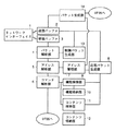
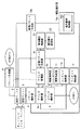
図1はこの発明の実施の形態の第1〜第8実施例に適用される家庭内の家電機器を接続する通信システムの全体構成図である。 FIG. 1 is an overall configuration diagram of a communication system for connecting domestic home appliances applied to the first to eighth examples of the embodiment of the present invention.
図1の通信システムは一般の家庭内に敷設されたデータパケットを伝送可能な伝送路37を含み、伝送路37には1階の居間のTV(テレビジョンの略)31およびVCR(ビデオカセットレコーダの略)36、2階の部屋のTV32およびステレオ33ならびに台所の電子レンジ34および冷蔵庫35のそれぞれが通信機能を有する家電機器として接続される。
The communication system shown in FIG. 1 includes a
図2は、図1の各家電機器のハードウェアブロック構成図である。図2において図1の各家電機器は、他の家電機器を制御可能なようにおよび他の家電機器から制御可能なように伝送路37を介して他の家電機器と通信するための通信制御部38および本来の機能、たとえばTVならば画面表示機能、冷蔵庫ならば冷却機能などを通信制御部38による通信動作と関連しながら実行するための機能実現部39を含む。
FIG. 2 is a hardware block diagram of each home appliance of FIG. In FIG. 2, each of the home appliances in FIG. 1 is a communication control unit for communicating with another home appliance via a
通信制御部38はCPU(中央処理装置の略)81、ROM(リードオンリメモリの略)82、メモリ83、RAM(ランダムアクセスメモリの略)84および伝送路37と通信制御部38との間の通信ならびに機能実現部39と通信制御部38との間の通信を制御するためのI/F(インタフェースの略)85を含む。機能実現部39はCPU91、ROM92、メモリ93、RAM94、通信制御部38と機能制御部39との間の通信を制御するためのI/F95、オペレータにより外部操作されて各種のデータを入力するための入力部96、各種のデータを出力するための出力部97および前述した本来の機能を処理するための機能部98を含む。
The
(実施例1)
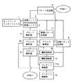
図3は、この発明の実施の形態の実施例1における図2の通信制御部38のシステム構成図である。
(Example 1)
FIG. 3 is a system configuration diagram of the
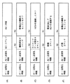
図4(A)〜(E)はこの発明の実施の形態の実施例1におけるパケットのフィールド構成図である。 FIGS. 4A to 4E are packet field configuration diagrams according to the first embodiment of the present invention.
図4(A)はパケットの基本フィールド構成を示す。図4(B)と(C)は問合せパケット、図4(D)は制御パケットおよび図4(E)は応答パケットである。図4(A)においてパケットは該パケットの送信元の家電機器を示すための送信元情報A1、該パケットの送信先の家電機器を示すための送信先情報A2、コマンドA3およびコマンドA3に関連する内容A4を含む。なお、図1に示される各家電機器には予め自己を一意に特定するためのアドレスが割当てられており、実施例1ではこのアドレスがパケットの送信元および送信先を指定するために用いられる。 FIG. 4A shows a basic field configuration of a packet. 4B and 4C show an inquiry packet, FIG. 4D shows a control packet, and FIG. 4E shows a response packet. In FIG. 4A, the packet relates to source information A1 for indicating the home electric appliance of the transmission source of the packet, destination information A2 for indicating the home electric appliance of the transmission destination of the packet, command A3 and command A3. Contains content A4. Note that an address for uniquely identifying itself is assigned in advance to each household electric device shown in FIG. 1, and in the first embodiment, this address is used to specify the source and destination of the packet.
図4(B)のパケットはコマンドA3および内容A4として家電機器の機能を問合せるコマンドおよび問合せの具体的内容を格納する。図4(C)のパケットはコマンドA3および内容A4として家電機器のコンテンツのデータを問合せるコマンドおよび問合せの具体的内容を格納する。図4(D)のデータパケットはコマンドA3および内容A4として家電機器の機能実現部98を制御するコマンドおよび制御の具体的内容が格納される。図4(E)のパケットのコマンドA3および内容A4には該パケットが応答のパケットであることを示すコマンドとその応答の具体的内容が格納される。
The packet in FIG. 4B stores a command for inquiring about the function of the home electric appliance and a specific content of the inquiry as the command A3 and the content A4. The packet in FIG. 4C stores a command for inquiring the data of the content of the home electric appliance and the specific content of the inquiry as the command A3 and the content A4. In the data packet of FIG. 4D, a command for controlling the
図3において通信制御部38はI/F85に関連して通信制御部38と伝送路37との通信を制御するためのネットワークI/F(以下、I/Fと略す)1、伝送路37に接続された他の家電機器へ送信するパケットが一時的に格納される送信バッファ2、伝送路37に接続された他の家電機器から受信したパケットが一時的に格納される受信バッファ3、受信バッファ3中の受信パケットを解析するためのパケット解析部4、パケット解析部4の解析により得られた受信パケット中の送信先情報と後述するアドレス管理部7中の自アドレス71とを比較するためのアドレス解析部5、受信パケットの解析により得られた受信パケット中のコマンドを解析するためのコマンド解析部6、アドレス管理部7、応答パケット生成部8、機能検索部9、機能格納部10、コンテンツ検索部11、コンテンツ格納部12、制御パケット生成部13およびパケット生成部14を含む。
In FIG. 3, a
送信バッファ2、受信バッファ3、アドレス管理部7、機能格納部10およびコンテンツ格納部12は図2のROM82、RAM84およびメモリ83上にデータを格納するための領域として構成される。図3のその他の各部はプログラムとしてROM82に予めストアされて、CPU81の制御のもとに実行されるか、または、ROM82の内容がRAM84に展開された後、CPU81の制御のもとに実行される。
The
図5は図3のアドレス管理部7の内容を示す図である。アドレス管理部7は自家電機器を一意に特定するために予め割当てられた自アドレス71、受信したパケット中の送信元情報A1である送信元アドレス72およびアドレステーブル73を含む。
FIG. 5 is a diagram showing the contents of the
送信元アドレス72は1つ以上記憶され、各アドレス72はパケットの受信の順番に従って記憶される。アドレステーブル73には図1の伝送路37に接続される家電機器73Aのそれぞれに対応してアドレス73Bが格納される。アドレス73Bは各家電機器の自アドレス71に一致する。
One or more source addresses 72 are stored, and each address 72 is stored according to the order of packet reception. The address table 73 stores an address 73B corresponding to each of the home electric appliances 73A connected to the
図6は図3の機能格納部10の内容の一例を示す図である。図7(A)〜(C)は図3のコンテンツ格納部12の内容例を示す図である。図8(A)および(B)は図4(E)の応答パケットの他の例およびさらなる他の例を示す図である。
FIG. 6 is a diagram showing an example of the contents of the
機能格納部10には家電機器が有する独自機能、すなわち機能部98により処理される機能が情報にして予め格納される。図6は家電機器がたとえば表示機能付カメラ一体型ビデオテープレコーダである場合の機能格納部10の内容を示す。この場合、機能格納部10には1つ以上の機能B1と機能B1のそれぞれに対応して機能に関する詳細情報B2が格納される。たとえば液晶表示機能を有すれば図6の映像出力機能に対応の詳細情報B2には“液晶”を示す情報が格納される。
The
機能検索部9は受信パケットの内容に従い機能格納部10に格納された機能情報を検索する。
The
コンテンツ格納部12には家電機器が有するコンテンツのデータが予め格納される。家電機器が、たとえばVCRであった場合、図7(A)では録画された内容を示すためのジャンルC1とタイトルC2が対応づけて格納され、図7(B)では録画の時間C3と録画指定されたTVのチャンネルを示す動作履歴C4が対応づけて格納される。
Content data stored in the
また、AV機器だけではなく、たとえば冷蔵庫35に関しては、コンテンツのデータはユーザにより手動入力、または食品に付いているバーコードを読取るなどの方法により入力される。図7(C)には冷蔵庫35のコンテンツ格納部12の一例が示される。図7(C)では食品名C5と入庫日C6が対応づけて格納される。
In addition to the AV equipment, for example, for the
コンテンツ検索部11は受信パケットの内容に基づいてコンテンツ格納部12のコンテンツのデータを検索する。
The
応答パケット生成部8はアドレス管理部7に格納された自アドレス71、送信元アドレス72、機能検索部9により検索して得られた機能情報およびコンテンツ検索部11により検索して得られたコンテンツのデータなどに基づいて図4(E)の応答パケットを生成し、送信バッファ2に格納する。
The response
制御パケット生成部13は所望する家電機器を制御するための図4(D)の制御パケットを生成して送信バッファ2に格納する。
The
パケット生成部14はI/F95を介して機能実現部39から与えられる指示内容に従って図4(B)または(C)の問合せパケットや制御パケットを生成し送信バッファ2に格納する。
The
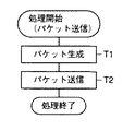
図9は、この発明の実施の形態の実施例1による家電機器におけるパケット送信の処理フローチャートである。 FIG. 9 is a flowchart of a packet transmission process in the household electrical appliance according to the first embodiment of the present invention.
パケット送信時、まずユーザが入力部96を操作して、要求を入力したことに応じて、CPU91はI/F95を介して入力された要求を通信制御部38に与える。
At the time of packet transmission, first, in response to the user operating the
通信制御部38のパケット生成部14は該要求を受取ると、要求内容に基づいて図4(A)のフィールド構成を有するパケットを生成し、送信バッファ2に格納する(T1)。
Upon receiving the request, the
I/F1は送信バッファ2に格納されたパケットを伝送路37を介して送信する(T2)。
The I /
図10はこの発明の実施の形態の実施例1における各家電機器のパケット受信時の処理フローチャートである。 FIG. 10 is a processing flowchart when each home appliance receives a packet according to the first embodiment of the present invention.
各家電機器において図4(A)のフィールド構成を有するパケットがI/F1を介して受信されると、受信パケットは受信バッファ3に格納される。
When a packet having the field configuration shown in FIG. 4A is received via each I /
次にパケット解析部4は受信バッファ3中の受信パケットの図示されないヘッダ情報に基づいて有効パケットか否か判定する(S1)。有効パケットでないと判定されると一連の処理は終了するが、有効パケットと判定されるとアドレス解析部5は受信パケット中の送信先情報A2により示される送信先アドレスとアドレス管理部7中の自アドレス71とを比較して、該受信パケットが自己宛のパケットか否か判定し、比較結果、一致すれば受信パケットは自己宛のパケットであるので、該受信パケット中の送信元情報A1により示される送信元アドレスをアドレス管理部7に送信元アドレス72として格納する(S2)。両アドレスが不一致であれば一連の処理は終了する。
Next, the
次にコマンド解析部6は受信パケットのコマンドA3に基づいて機能問合せコマンドか否かを判定する(S3)。
Next, the
コマンドA3が機能問合せコマンドと判定されると、機能検索部9は受信パケットの内容A4に基づいて機能格納部10中の複数の機能B1を検索し、検索結果、問合せの機能に一致する機能B1が格納部10中に格納されていれば、処理は応答パケット生成部8に移行する(S4)。
When the command A3 is determined to be a function inquiry command, the
一方、受信パケットのコマンドA3は機能の問合せコマンドでないと判定されると(S3でNO)、コマンド解析部6はコマンドA3はコンテンツの問合せコマンドか否か判定する(S5)。
On the other hand, if it is determined that the command A3 of the received packet is not a function inquiry command (NO in S3), the
コマンドA3はコンテンツの問合せコマンドと判定されると(S5でYES)、コンテンツ検索部11は受信パケットの内容A4に基づいてコンテンツ格納部12中のコンテンツのデータを検索して、検索結果、問合せの内容に一致のコンテンツデータが格納部12中に格納されていれば、処理は応答パケット生成部8に移行する。
If the command A3 is determined to be a content inquiry command (YES in S5), the
一方、コマンドA3はコンテンツの問合せコマンドでないと判定されると(S5でNO)、該コマンドは機能実現部39のI/F95に与えられて、CPU91の制御のもとに実行される(S8)。
On the other hand, if it is determined that the command A3 is not a content inquiry command (NO in S5), the command is given to the I /
一方、応答パケット生成部8はアドレス管理部7中の自アドレス71および送信元アドレス72を送信元情報A1および送信先情報A2とし、コマンドA3を問合せに対応する応答であることを示すコマンドとし、内容A4を問合せに対する応答の具体的内容とした図4(E)の応答パケットを生成して送信バッファ2に格納する(S9)。
On the other hand, the response
次に、I/F1は送信バッファ2に格納された応答パケットを伝送路37に送信する。
Next, the I /
ここで、応答パケット生成部8は、受信パケットがたとえば図4(B)の機能問合せパケットであれば、図8(A)の応答パケットを生成し、たとえば図4(C)のコンテンツデータ問合せパケットであれば図8(B)の応答パケットを生成する。
Here, if the received packet is, for example, the function inquiry packet of FIG. 4B, the response
図8(A)の応答パケットには内容A4として問合せられた内容に応じた図5の機能B1と対応の詳細情報B2が格納され、図8(B)の応答パケットには内容A4として問合せられた内容に応じた図7(B)の時間C3と動作履歴C4が格納される。 The response packet of FIG. 8A stores the function B1 of FIG. 5 and the corresponding detailed information B2 corresponding to the content queried as the content A4, and the response packet of FIG. 8B is queried as the content A4. The time C3 and the operation history C4 in FIG.
各家電機器でこの応答パケットが受信されると、図10のS1〜S8の処理を経て、受信パケットはコマンド解析部6から機能実現部39に与えられ、その内容が出力部97に表示される。したがってユーザは表示内容を見て各家電機器のIDやアドレスと、それが有する機能やコンテンツに関する情報を確認できる。
When each home appliance receives this response packet, the received packet is provided from the
なお、機能検索部9またはコンテンツ検索部11による検索結果、問合せの機能またはコンテンツのデータが得られなかった場合には、受信パケットを破棄または問合せを受けた機能またはコンテンツは有してないなどの内容A4を格納した図4(E)の応答パケットを送信するようにしてもよい。
If the
実施例1では各家電機器は外部からの問合せに応じて、自機器内に格納している自機器の有する機能に関する情報またはコンテンツデータを検索し、検索結果を自機器を特定するアドレスを格納した応答パケットとして送信する。これにより、各家電機器やネットワーク内の他の家電機器の機能を使用したい場合に、制御対象となる機能またはコンテンツを有する他の家電機器のアドレスの取得が容易に可能となるので、該ネットワークにおいては各家電機器のアドレスと各家電機器が有する機能に関する情報とを関連づけて格納したテーブルは不要となる。 In the first embodiment, in response to an inquiry from the outside, each home appliance searches for information or content data related to the function of the own device stored in the own device, and stores the search result in an address for specifying the own device. Send as a response packet. Thereby, when it is desired to use the function of each household electric device or another household electric device in the network, it is possible to easily obtain the address of another household electric device having the function or the content to be controlled. Does not require a table storing the addresses of the respective home appliances in association with the information on the functions of the respective home appliances.
また、このネットワークでは中央制御装置のような特別な制御機器を用いなくても、各家電機器の機能をネットワーク上で共有できる。また、必要に応じて機能情報またはコンテンツのデータの問合せが行なわれるので、ネットワークにおける家電機器の追加または削除などによるテーブルの更新処理などは不要となる。 Also, in this network, the functions of each household electric appliance can be shared on the network without using a special control device such as a central control device. In addition, since the inquiry about the function information or the content data is performed as needed, a table updating process by adding or deleting a home electric appliance in the network becomes unnecessary.
(実施例2)
図11はこの発明の実施の形態の実施例2における図2の通信制御部38のシステム構成図である。図3の構成と図11のそれとを比較し異なる点は受信パケット中のアドレス解析の直後に機能情報の検索およびコンテンツデータの検索が行なわれるように、図3のアドレス解析部5、機能検索部9およびコンテンツ検索部11のそれぞれは図11のようにアドレス解析部5a、機能検索部9aおよびコンテンツ検索部11aのそれぞれで代替された点にある。図11のその他の各部分は図3のそれと共通するので説明は省略する。
(Example 2)
FIG. 11 is a system configuration diagram of the
図12はこの発明の実施の形態の実施例2における各家電機器のパケット受信の処理フローチャートである。図13(A)〜(C)はこの発明の実施の形態の実施例2における制御パケットと応答パケットを示す図である。図13(A)の制御パケットには送信元情報A1として図1のVCR36のアドレスが、送信先情報A2として「映像表示機能を持っている機器」という内容の情報が、コマンドA3として「画像を表示するコマンド」が、および内容A4としてコマンドA3に関連して表示すべき画像データがそれぞれ格納される。図13(B)の制御パケットには送信元情報A1として図1のVCR36のアドレスが、送信先情報A2として「映画のタイトルを有する機器」という内容の情報が、コマンドA3として「映画のタイトルを送信するコマンド」がそれぞれ格納される。図13(C)の応答パケットには送信元情報A1として図1のTV31のアドレスが、送信先情報A2としてVCR36のアドレスが、コマンドA3として応答コマンドが、内容A4として受信コマンドを実行した結果がそれぞれ格納される。図13(C)の応答パケットは図13(A)または(B)の制御パケット中のコマンドA3の実行結果を送信するためのパケットである。
FIG. 12 is a flowchart of a packet reception process of each home appliance according to the second embodiment of the present invention. FIGS. 13A to 13C are diagrams showing a control packet and a response packet according to the second embodiment of the present invention. In the control packet shown in FIG. 13A, the address of the
まず、図1のVCR36から図9のフローチャートに従って図13(A)の制御パケットが生成されて伝送路37を介して他のすべての家電機器に送信される。
First, the control packet of FIG. 13A is generated from the
各家電機器では図13(A)の制御パケットがI/F1を介して受信されて受信バッファ3に格納される。
In each home appliance, the control packet of FIG. 13A is received via the I /
まず、パケット解析部4は受信パケットのヘッダ情報に基づき有効パケットか否か判定する(S11)。有効パケットでなければ一連の処理は終了するが、有効パケットであればアドレス解析部5aは受信パケットの送信先情報A2がアドレス管理部7中の自アドレス71と一致するか否か判定する。一致すれば、受信パケット中の送信元情報A1が送信元アドレス72としてアドレス管理部7に格納されて(S15)、コマンドA3が解析されて実行される(S17、S18)。
First, the
一方、送信先情報A2と自アドレス71とが不一致ならば、アドレス解析部5aは機能情報により送信先情報A2が示されるか否か判定される(S13)。送信先情報A2が機能情報を用いて示されていれば、機能検索部9aは送信先情報A2で示される機能情報と機能格納部10中のいずれかの情報と一致するか判定する。一致すれば、コマンドA3が解析されて実行されるが(S17、S18)、不一致ならば一連の処理を終了する。
On the other hand, if the destination information A2 and the own address 71 do not match, the
一方、送信先情報A2が機能情報により示されていなければ、コンテンツ検索部11aは送信先情報A2で示される情報とコンテンツ格納部12中のコンテンツに関するいずれかの情報と一致するか判定する(S16)。一致すればコマンドA3が解析されて実行される(S17、S18)。不一致ならば一連の処理は終了する。
On the other hand, if the destination information A2 is not indicated by the function information, the
ここで、図12のコマンドの解析と実行について説明する。たとえば、受信パケットが図13(A)の制御パケットであった場合には、送信先情報A2で示される「映像表示機能を持っている機器」、すなわち映像表示機能を有する図1のTV31および32において画像表示するコマンドA3が実行されて、機能部98のブラウン管などのディスプレイに内容A4の画像データが表示される。このとき、応答パケット生成部8により図13(C)の応答パケットが生成されて受信パケット中のコマンドA3の実行結果を送信するようにしてもよい。
Here, analysis and execution of the command in FIG. 12 will be described. For example, if the received packet is the control packet shown in FIG. 13A, the "device having a video display function" indicated by the destination information A2, that is, the
また、たとえば受信パケットが図13(B)の制御パケットであった場合には、送信先情報A2で示される「映画のタイトルを持っている機器」、すなわちコンテンツデータとして映画のタイトルを持っている図1のVCR36において映画のタイトルを送信するコマンドA3が実行される。このとき、応答パケット生成部8により内容A4としてコンテンツ格納部12中の映画のタイトルが格納された図13(C)の応答パケットが生成されて、送信されるようにしてもよい。
Further, for example, when the received packet is the control packet shown in FIG. 13B, “the device having the title of the movie” indicated by the destination information A2, that is, the title of the movie as the content data. A command A3 for transmitting a movie title is executed in the
なお、受信パケット中の送信先情報A2で指定される家電機器に自機器が該当しない場合には、受信パケットを破棄、または問合せを受けた機能またはコンテンツデータを有していない旨の情報を内容A4として格納した応答パケットを送信するようにしてもよい。 If the home appliance does not correspond to the home appliance specified by the destination information A2 in the received packet, the received packet is discarded, or information indicating that the device does not have the function or the content data for which the inquiry has been received is included. The response packet stored as A4 may be transmitted.
このように実施例2では、受信パケットの送信先情報A2の解析時に、機能やコンテンツの検索が可能となる。そのため、たとえば「映像出力が可能な機器すべて」や「×××という映画のタイトルを持つ機器すべて」など、ある機能情報やコンテンツデータを有するすべての家電機器をコマンドA3を実行する対象機器として一括指定することが可能となる。 As described above, in the second embodiment, it is possible to search for a function or content when analyzing the destination information A2 of the received packet. Therefore, for example, all home appliances having certain function information or content data, such as "all devices capable of outputting video" and "all devices having a movie title of xxx", are collectively designated as devices to execute command A3. It can be specified.
それゆえに、ある機能情報またはコンテンツデータを持ったすべての機器を制御する場合に、送信する制御パケットの数を減少させることができて、伝送路37などの通信媒体を有効に活用できる。
Therefore, when controlling all devices having certain function information or content data, the number of control packets to be transmitted can be reduced, and a communication medium such as the
(実施例3)
図14はこの発明の実施の形態の実施例3における図2の通信制御部38のシステム構成図である。図14のシステム構成と図11のそれとを比較して異なる点は、図11の応答パケット生成部8に代替して応答パケット生成部8aを有し、かつ入力部15、出力部16および情報識別子格納部17を追加して有する点にある。その他の構成は図11のそれと同様であり、説明は省略する。
(Example 3)
FIG. 14 is a system configuration diagram of the
情報識別子格納部17は機能格納部10およびコンテンツ格納部12に格納された機能情報およびコンテンツデータのそれぞれを識別するための文字や数字などからなる利用者の認識可能な識別子を予め格納する。応答パケット生成部8aは、応答パケットを生成する際に応答パケットに検索された機能情報またはコンテンツデータに対応する情報識別子格納部17中の情報識別子を内容A4として格納する。
The information
なお、情報識別子格納部17への情報識別子の設定は手入力、自動的に機能格納部10およびコンテンツ格納部12中の機能情報およびコンテンツデータの一部から作成して入力するなどの方法が利用される。
The setting of the information identifier in the information
入力部15は利用者により操作されて外部からデータを入力するためのものであり、たとえばキーボードなどからなる。出力部16は外部にデータ出力するためのものであり、たとえばディスプレイなどからなる。
The
図15は図14の情報識別子格納部17の内容を示す図である。図15には図1のTV31の情報識別子格納部17の例が示される。図15ではTV31の映像出力機能には「居間に設置しているTVの画面」という情報識別子17Aが対応する。
FIG. 15 is a diagram showing the contents of the information
図16はこの発明の実施の形態の実施例3におけるパケット受信に応じた応答パケット送信のフローチャートであり、図17はこの発明の実施の形態の実施例3におけるパケット受信に応じた制御パケット送信の処理フローチャートである。 FIG. 16 is a flowchart of response packet transmission in response to packet reception in Example 3 of the embodiment of the present invention. FIG. 17 is a flowchart of control packet transmission in response to packet reception in Example 3 of the embodiment of the present invention. It is a processing flowchart.
図18(A)と(B)は、図16および図17の処理フローチャートに従って送信される応答パケットおよび制御パケットの一例を示す図である。 FIGS. 18A and 18B are diagrams showing an example of a response packet and a control packet transmitted according to the processing flowcharts of FIGS.
まず、VCR36が実施例1と同様にシステム内の各家電機器に図4(B)の問合せパケットを生成して送信したと想定する。このとき、各家電機器ではこの問合せパケットを図16のフローチャートに従って受信処理する。
First, it is assumed that the
なお、図16のS19〜S25の処理内容は図10のS1〜S8のそれと同じなので説明は省略する。 The processing contents of S19 to S25 in FIG. 16 are the same as those of S1 to S8 in FIG.
各家電機器は受信した問合せパケットが自己宛のもので、かつ問合せパケット中の内容A4で示される機能情報が機能格納部10中にあれば、図18(A)の応答パケットが応答パケット生成部8aにより生成される(S26)。応答パケット生成部8aは情報識別子格納部17から機能格納部10から得られた機能情報に対応する情報識別子17Aを読出して応答パケットに内容A4として格納する。これにより図18(A)の応答パケットが生成され送信バッファ2を介して送信される(S27)。
If the received inquiry packet is addressed to itself and the function information indicated by the content A4 in the inquiry packet is in the
この場合、問合せの内容A4に一致した機能情報あるいはコンテンツデータを有するTV31以外の各家電機器からも同様に情報識別子17Aが格納された図18(A)の応答パケットが送信されるので、VCR36は複数の家電機器から応答パケットを受信できる。 In this case, the response packet of FIG. 18A in which the information identifier 17A is similarly stored is transmitted from each household electrical appliance other than the TV 31 having the function information or the content data that matches the content A4 of the inquiry. Response packets can be received from multiple home appliances.
図17において、VCR36では受信した応答パケットのそれぞれからパケット解析部4により情報識別子17Aが抽出されて、出力部16に表示される(S28、S29)。利用者は出力部16に表示された複数の情報識別子17Aから所望する情報識別子17Aを入力部15を用いて選択する。制御パケット生成部13は選択された情報識別子17Aを有する家電機器宛の図18(B)の制御パケットを生成し、送信バッファ2を介して送信する(S30、S31)。
In FIG. 17, in the
なお、制御パケット生成部13は選択された識別子17Aに基づいてアドレス管理部7中のアドレステーブル73から対応する機器73Aのアドレス73Bを読出し、これと自アドレス71と入力部15から利用者により入力された制御コマンドとに基づいて図18(B)の制御パケットを生成する。
The control
VCR36から送信された制御パケットを受信した家電機器では、図16のフローチャートに従って受信した制御パケット中のコマンドA3に従った処理が実行される。
In the home electric appliance which has received the control packet transmitted from the
実施例3によれば問合せに対して複数の家電機器から応答があった場合に、応答した複数の機器に関する情報識別子17Aを利用者に提示して、利用者に制御を所望する機器を選択させることができる。 According to the third embodiment, when a plurality of home appliances respond to the inquiry, the information identifier 17A relating to the plurality of responded appliances is presented to the user, and the user selects the device desired to be controlled. be able to.
(実施例4)
図19はこの発明の実施の形態の実施例4における図2の通信制御部38のシステム構成図である。
(Example 4)
FIG. 19 is a system configuration diagram of the
図19のシステム構成と図14のそれとを比較して異なる点は、応答パケット生成部8aに代替して応答パケット生成部8bを設け、制御パケット生成部13、入力部15および出力部16に代替して制御パケット生成部13aおよび機器選択部18を設け、さらに情報識別子格納部17に代替して能力レベル格納部19を設ける点にある。図19のその他の部分は図14のそれと同じであり説明は省略する。
The difference between the system configuration of FIG. 19 and that of FIG. 14 is that a
図20は図19の能力レベル格納部19の内容を示す図である。能力レベル格納部19は、対応の家電機器が有するそれぞれの機能19Aに対応してその機能をどれぐらい実現する能力があるかを、たとえば数値で示す能力レベル情報19Bが格納される。能力レベル情報19Bは同一機能を1つ以上の機器が有する場合に各機器による該機能実現時の能力レベルを相対的に示すものである。
FIG. 20 is a diagram showing the contents of the capability
応答パケット生成部8bは能力レベル格納部19中の能力レベル情報19Bが内容A4として格納された応答パケットを生成する。このとき、応答パケットに格納される能力レベル情報は機能検索部9aの検索結果に基づいて決定される。
The
機器選択部18は選択基準格納部181を有し、受信パケット中の能力レベル情報19Bを格納部181中に予め格納された選択基準レベルと比較して、その比較結果に基づいて制御パケット送信先の機器を選択する。
The device selection unit 18 has a selection
制御パケット生成部13aは機器選択部18で選択された機器を制御するための制御パケットを生成する。 The control packet generator 13a generates a control packet for controlling the device selected by the device selector 18.
なお、能力レベル格納部19中の能力レベル情報19Bはたとえば映像出力機能に対しては大型のTVであれば“5”、小型の携帯可能なTVであれは“1”などのように、手入力により設定したり、予め機器ごとに固定して設定したり、該機器をネットワーク接続したときに設定したりするようにしてもよい。
The capability level information 19B in the capability
図21はこの発明の実施の形態の実施例4におけるパケット受信に応じた応答パケット送信の処理フローチャートである。図22はこの発明の実施の形態の実施例4におけるパケット受信に応じた制御パケット送信の処理フローチャートである。
FIG. 21 is a processing flowchart of response packet transmission in response to packet reception in
図23(A)と(B)は図21と22の処理フローチャートに従って処理される問合せパケットと応答パケットの一例を示す図である。 FIGS. 23A and 23B are diagrams showing an example of an inquiry packet and a response packet processed according to the processing flowcharts of FIGS. 21 and 22.
まず、VCR36がシステム内の各機器に「映像出力機能を持っているか」の図23(A)の問合せパケットを生成して送信したと想定する。
First, it is assumed that the
このとき、各家電機器では、この問合せパケットを図21のフローチャートに従って受信処理する。なお、図21のS32〜S38の処理内容は図10のS1〜S8のそれと同じなので説明は省略する。 At this time, each home appliance receives the inquiry packet according to the flowchart of FIG. The processing contents of S32 to S38 in FIG. 21 are the same as those of S1 to S8 in FIG.
各家電機器は受信した問合せパケットが自己宛のもので、かつ問合せパケット中の内容A4で示される機能情報が機能情報格納部10中にあれば、図23(B)の応答パケットが応答パケット生成部8bで次のように生成される。
If the received inquiry packet is addressed to itself and the function information indicated by the content A4 in the inquiry packet is in the function
まず、応答パケット生成部8bはアドレス管理部7中の自アドレス71、送信元アドレス72、および能力レベル格納部19中の問合せられた機能19Aに対応の能力レベル情報19Bを送信元情報A1、送信先情報A2および内容A4としてそれぞれ格納した図23(B)の応答パケットを生成する(S39)。生成された応答パケットは送信バッファ2を介して送信される(S40)。
First, the response
VCR36では図23(A)の問合せパケットを送信したことにより図23(B)の応答パケットを受信する。図22においてパケット解析部4では受信した応答パケットから能力レベル情報19Bを抽出して、機器選択部18に与える(S41)。
The
機器選択部18では与えられた能力レベル情報19Bと選択基準格納部181中の選択基準とに基づいて、該応答パケット送信元の機器を制御対象機器として選択するか否か決定する。たとえば、複数の応答パケットを受信して複数の能力レベル情報19Bを得た場合に、最も能力レベルの高い機器を選択するという選択基準が設定されていたとすれば、最も映像出力機能に優れた機器が制御対象として選択される(S42)。
The device selection unit 18 determines whether to select the response packet transmission source device as the control target device based on the given capability level information 19B and the selection criterion in the selection
次に、制御パケット生成部13aは選択部18から何番目に受信された応答パケットに対応の機器が選択されたかが指示されるので、応じてアドレス管理部7から指示された応答パケットに対応の送信元アドレス72と自アドレス71を読出し、読出されたこれらアドレスと予め与えられたあるいは設定されていた制御コマンドを用いて図4(D)の制御パケットを生成する(S43)。
Next, the control packet generating unit 13a is instructed from what order the response packet received from the selecting unit 18 is selected, and accordingly, the control packet generating unit 13a transmits the response packet corresponding to the response packet instructed from the
生成された制御パケットは送信バッファ2に格納された後、I/F1を介して送信されるので(S44)、選択された家電機器ではこの制御パケットを受信して受信パケットの内容に応じた処理が行なわれる。
Since the generated control packet is stored in the
実施例4では、応答パケット中の能力レベル情報19Bをもとに、問合せた機能を実現するのに適した家電機器が自動的に選択される。 In the fourth embodiment, a home appliance suitable for realizing the inquired function is automatically selected based on the capability level information 19B in the response packet.
(実施例5)
図24はこの発明の実施の形態の実施例5における図2の通信制御部38のシステム構成図である。
(Example 5)
FIG. 24 is a system configuration diagram of the
図24のシステム構成と図19のそれとを比較して異なる点は、応答パケット生成部8b、制御パケット生成部13aおよび機器選択部18のそれぞれに代替して応答パケット生成部8c、制御パケット生成部13bおよび機器選択部18aを設け、かつ能力レベル格納部19に代替して優先順位設定部20および優先順位格納部21を設けた点にある。図24のその他の部分は図19のそれと同じであり説明は省略する。
The difference between the system configuration of FIG. 24 and that of FIG. 19 is that the
本実施例では機能ごとに、その機能を実行する機器の優先順位が優先順位設定部20で予め設定されて優先順位格納部21に格納される。応答パケット生成部8cは、優先順位格納部21中の優先順位情報を格納した応答パケットを生成する。
In this embodiment, for each function, the priority order of the device executing the function is set in advance by the priority
図25は図24の優先順位格納部21の内容を示す図である。図25を参照して、優先順位格納部21にはそれぞれの機能21Aに対応して機器ごとに実行のための優先順位を、たとえば数値にして示す優先順位情報21Bが格納される。
FIG. 25 is a diagram showing the contents of the priority
各家電機器では、予め優先順位設定部20により、たとえば映像出力機能の優先順位情報については、図1の居間に設置されたTV31が“1”、2階の部屋に設置されたTV32が“2”などのように設定される。このように複数の家電機器が有する機能のそれぞれについて、家電機器ごとに該機能の実行に関する優先順位情報21Bが設定されて、優先順位格納部21に格納される。なお、優先順位の決定については手動による入力で任意に決定、または家電機器の設置場所に応じて決定するなどのような方法が採用される。
In each of the home electric appliances, the priority
上述した実施例4の能力レベル情報は機能について各家電機器がその機能を実現できる能力の程度を示すものであるが、本実施例の優先順位は、それとは異なりその機能を実現する際に優先して使用される家電機器が示されるものである。したがって、能力レベル情報と優先順位情報とを併用し、利用の状況や時間帯、機能実現で行なわれる作業の内容などに応じて能力レベル情報と優先順位情報とを使い分けるようにしてもよい。 Although the capability level information of the fourth embodiment described above indicates the degree of capability of each home appliance for the function, the priority of the present embodiment is different from that of the fourth embodiment when the function is realized. The home appliance used as the home appliance is shown. Therefore, the capability level information and the priority information may be used in combination, and the capability level information and the priority information may be selectively used according to the use situation, the time zone, the content of the work performed in realizing the function, and the like.
応答パケット生成部8cは優先順位格納部21中の優先順位情報21Bが内容A4として格納された応答パケットを生成する。このとき、格納される優先順位情報21Bは機能検索部9aの検索結果に基づいて決定される。
The response packet generator 8c generates a response packet in which the priority information 21B in the
機器選択部18aは選択基準格納部182を有し、受信パケット中の優先順位情報21Bと格納部182中に予め格納された選択基準レベルと比較して、比較結果に基づいて制御パケット送信先の家電機器を選択し、選択結果を制御パケット生成部13bに与える。
The device selection unit 18a has a selection
制御パケット生成部13bは与えられた選択結果に基づいて選択された家電機器を制御するための制御パケットを生成する。
The
図26はこの発明の実施の形態の実施例5におけるパケット受信に応じた応答パケット送信の処理フローチャートである。
FIG. 26 is a processing flowchart of response packet transmission in response to packet reception in
図27はこの発明の実施の形態の実施例5におけるパケット受信に応じた制御パケット送信の処理フローチャートである。
FIG. 27 is a processing flowchart of control packet transmission in response to packet reception in
図28(A)と(B)は図26と図27の処理フローチャートに従って処理される問合せパケットと応答パケットの一例を示す図である。 FIGS. 28A and 28B are diagrams showing an example of an inquiry packet and a response packet processed according to the processing flowcharts of FIGS. 26 and 27.
まずVCR36がシステム内の各家電機器に内容A4として「映像出力機能を持っているか」が格納された図28(A)の問合せパケットを生成して送信したと想定する。
First, it is assumed that the
このとき、各家電機器では、図28(A)の問合せパケットを図26のフローチャートに従って処理する。なお、図26のS45〜S51の処理内容は図10のS1〜S8のそれと同じなので説明は省略する。 At this time, each home electric appliance processes the inquiry packet of FIG. 28A according to the flowchart of FIG. The processing contents of S45 to S51 in FIG. 26 are the same as those of S1 to S8 in FIG.
各家電機器は受信した問合せパケットが自己宛のもので、かつ、問合せパケット中の内容A4で示される機能情報が機能格納部10中にあれば、図28(B)の応答パケットが応答パケット生成部8cで次のように生成される。
If the received inquiry packet is addressed to itself and the function information indicated by the content A4 in the inquiry packet is in the
まず、応答パケット生成部8cはアドレス管理部7中の自アドレス71、送信元アドレス72、および優先順位格納部21中の問合せられた機能21Aに対応の優先順位情報21Bをそれぞれ送信元情報A1、送信先情報A2および内容A4にそれぞれ格納した図28(B)の応答パケットを生成する(S52)。生成された応答パケットは送信バッファ2を介して送信される(S53)。
First, the response packet generating unit 8c stores the source address A1, the source address 72 in the
図27においてVCR36のパケット解析部4では順次受信する図28(B)の応答パケットから優先順位情報21Bを抽出して機器選択部18aに与える(S54)。
In FIG. 27, the
機器選択部18aでは与えられる優先順位情報21Bと、最も優先順位の高い機器を選択するなどの選択基準格納部182中の選択基準とにより制御対象となる家電機器を選択し選択結果として制御パケット生成部13bに与える(S55)。制御パケット生成部13bは選択結果に基づいてアドレス管理部7から対応する送信元アドレス72を読出して、予め与えられた制御コマンドと読出された送信元アドレス72などを用いて、たとえば図4(D)の制御パケットを送信し、送信バッファ2に格納する(S56)。
The device selection unit 18a selects a home appliance to be controlled based on the given priority information 21B and a selection criterion in the selection
送信バッファ2に格納された制御パケットは、I/F1を通じて送信される(S57)。したがって優先順位情報21Bを用いて選択された家電機器では制御パケットが受信されて受信された制御パケットの内容に従う処理が実行される。
The control packet stored in the
なお、本実施例では優先順位情報21Bを各家電機器で持つとしたが、ネットワーク内のいずれか1つの家電機器がすべての家電機器に関する優先順位情報21Bを持ち、その機器に対して優先順位を問合せるようにしてもよい。また、すべての家電機器のそれぞれがすべての家電機器に関する優先順位情報21Bを持つようにしてもよい。 In the present embodiment, it is assumed that each home appliance has the priority information 21B. However, any one of the home appliances in the network has the priority information 21B regarding all the home appliances, and the priority is assigned to the home appliances. An inquiry may be made. Alternatively, all the home appliances may have the priority information 21B regarding all the home appliances.
このように実施例5では機能ごとにその機能を実現する家電機器の優先順位を利用状況など使い勝手よく予め設定しておくだけで、優先順位情報21Bに従って制御対象となる家電機器の選択を自動的に行なうことができる。 As described above, in the fifth embodiment, the priorities of the home electric appliances realizing the functions are simply set in advance for each function with ease of use, such as the usage status, and the selection of the home electric appliances to be controlled is automatically performed according to the priority information 21B. Can be performed.
したがって、利用者が所望する機能を実現するために最も適切な家電機器を制御対象として選択することが容易に可能となる。 Therefore, it becomes easy for the user to select the most appropriate home electric appliance as a control target in order to realize a desired function.
以上のように実施例3〜5では、家電機器からの機能情報またはコンテンツデータの問合せに対して、複数の家電機器から応答があった場合の処理について説明した。実施例3ではこの処理のために出力部を介して利用者に問合せを行ない、利用者が制御対象とする家電機器を選択する方法について示した。実施例4と5では、利用者に問合せをすることなく、機器選択部により制御対象とする機器を選択する方法が示される。実施例4では能力レベル情報を用いた選択が行なわれ、実施例5では能力レベル情報の代わりに設定の自由度のより高い優先順位情報を利用して機器の選択が行なわれる。 As described above, in the third to fifth embodiments, the processing in the case where a plurality of home appliances responded to the inquiry about the function information or the content data from the home appliances has been described. In the third embodiment, a method is described in which a user is inquired via the output unit for this processing, and the user selects a home electric appliance to be controlled. Embodiments 4 and 5 show a method of selecting a device to be controlled by the device selection unit without inquiring the user. In the fourth embodiment, the selection using the capability level information is performed. In the fifth embodiment, the device selection is performed using the priority information having a higher degree of freedom in setting instead of the capability level information.
(実施例6)
図29は、この発明の実施の形態の実施例6における図2の通信制御部38のシステム構成図である。
(Example 6)
FIG. 29 is a system configuration diagram of the
図29のシステム構成と図24のそれとを比較して異なる点は、応答パケット生成部8cが応答パケット生成部8dに代替され、優先順位格納部21、優先順位設定部20、機器選択部18aおよび制御パケット生成部13bに代替して、ビジー状態判定部22、ビジー理由格納部23およびビジーパケット生成部24を備えた点にある。図29のその他の部分は図24のそれと同じなので説明は省略する。
The difference between the system configuration of FIG. 29 and that of FIG. 24 is that the response packet generation unit 8c is replaced by the response
図30は図29のビジー理由格納部23の内容を示す図である。
FIG. 30 is a diagram showing the contents of the busy
ビジー状態判定部22は受信した制御パケット中の制御コマンドに従う処理が機能実現部39において実行可能か否か、機能実現部39から与えられるビジーデータBDに基づいて判定する。ビジーデータBDは機能実現部39において現在処理(実行)されている機能を一意に示すもので、たとえば数値が設定される。
The busy
ビジー理由格納部23は図30に示されるように予め複数のビジー理由23Aが格納されて、ビジーデータBDに基づいてアクセスされる。したがって、ビジーデータBDが示す現在実行中の機能の詳細はデータBDに対応のビジー理由23Aで詳細に示される。なお、ここでは各家電機器の機能実現部39である機能が実行中で他の機能を実行することができないような状態をビジー状態という。ビジーデータBDはこのビジー状態の要因となっている機能を一意に示すデータであり、ビジー状態ではないときはたとえば値“0”となる。
The busy
ビジーパケット生成部24はビジー状態判定部22で対応の機能実現部39はビジー状態と判定された場合に応答パケットであるビジーパケットを生成する。
The busy
図31はこの発明の実施の形態の実施例6における制御パケット受信に応じた処理フローチャートである。
FIG. 31 is a processing flowchart in response to control packet reception in
図32(A)と(B)は図31の処理フローチャートで処理される制御パケットと応答パケットの一例を示す図である。今、VCR36の入力部96をユーザが操作して、機能部98で記録された画像データを1階の居間のTV31に表示させる旨の要求が入力がされたと想定すると、図32(A)の制御パケットがパケット生成部14で生成されて送信される。
FIGS. 32A and 32B are diagrams showing an example of a control packet and a response packet processed in the processing flowchart of FIG. Now, assuming that the user operates the
TV31は図32(A)の制御パケットを受信すると、図10と同様の処理フローチャートのS1〜S7の処理に従って、コマンド解析部6でコマンド処理する(S8)。コマンド解析部6は制御パケット中のコマンドは画像データを表示するためのコマンドであることを解釈して、ビジー状態判定部22に処理を移す。
When the TV 31 receives the control packet of FIG. 32A, the
図31においてビジー状態判定部22は与えられるビジーデータBDに基づいて対応の機能実現部39がビジー状態であるか否か判定する(S58)。
In FIG. 31, the busy
ビジー状態でないと判定されると、コマンド解析部6に対してコマンド処理が要求されるとともに、応答パケット生成部8dにより、たとえばコマンド実行結果を格納した図13(C)のような応答パケットが生成されて送信される(S59)。
If it is determined that it is not busy, command processing is requested to the
一方、対応の機能部98でTV放送の画像表示中であってビジー状態と判定されると、ビジーパケット生成部24はビジーデータBDに基づいてビジー理由格納部23をアクセスして得られたビジー理由23A、ならびにアドレス管理部7を参照して得られた自アドレス71および送信元アドレス72を用いて図32(B)のビジーパケットを生成する(S60)。
On the other hand, if the
生成されたビジーパケットは送信バッファ2に格納されて送信される(S61)。
The generated busy packet is stored in the
実施例6では各家電機器において制御パケットを受信した際に、ビジー状態と判定された場合には、ビジー理由32Aが格納されたビジーパケットが送信されるので、制御側の家電機器は被制御側の家電機器が所望される機能を持っていないのか、または現在ビジー状態のため所望される機能を実行できないのかを容易に判別できる。また、制御側の家電機器はビジー理由32Aを受理するので、どのような理由(状態)で所望される機能が実行できないのかを認識することができる。 In the sixth embodiment, when a control packet is received in each home appliance, if a busy state is determined, a busy packet in which the busy reason 32A is stored is transmitted. It is possible to easily determine whether the home electric appliance does not have the desired function or cannot execute the desired function because it is currently busy. Further, since the control-use home electric appliance receives the busy reason 32A, it can recognize for what reason (state) the desired function cannot be executed.
(実施例7)
図33は、この発明の実施の形態の実施例7における図2の通信制御部38のシステム構成図である。
(Example 7)
FIG. 33 is a system configuration diagram of the
図33のシステム構成と図29のそれとを比較して異なる点は、表示デバイスなどからなる各種データを出力するための出力部15a、ユーザにより操作されて各種データを入力するための入力部16a、割込パケット生成部25および割込処理実行部26が追加された点にある。図33のその他の部分は図29のそれと同じなので説明は省略する。
The system configuration of FIG. 33 is different from that of FIG. 29 in that an
割込パケット生成部25は入力部16aから入力された割込要求に応答して割込パケットを生成し、送信バッファ2に格納する。
The interrupt
割込処理実行部26は割込パケットを受信すると、割込パケット中のコマンドをビジー状態である機能実現部39にI/F95を介して与える。これにより、機能実現部39ではCPU91によりコマンド解釈されて、機能部98で実行中の処理は割込がかけられて中断され、解釈結果に基づく新たな処理が実行開始される。
Upon receiving the interrupt packet, the interrupt
図34はこの発明の実施の形態の実施例7におけるビジーパケット受信に応じた処理フローチャートである。
FIG. 34 is a processing flowchart in response to a busy packet reception in
図35はこの発明の実施の形態の実施例7における割込パケット受信に応じた処理フローチャートである。 FIG. 35 is a processing flowchart in response to the reception of an interrupt packet according to the seventh embodiment of the present invention.
図36はこの発明の実施の形態の実施例7における割込パケットの一例を示す図である。 FIG. 36 is a diagram showing an example of an interrupt packet according to the seventh embodiment of the present invention.
図36の割込パケットにはコマンドA3として割込コマンドおよび割込により実行開始されるコマンドが格納される。 In the interrupt packet of FIG. 36, an interrupt command and a command started to be executed by the interrupt are stored as the command A3.
図34において前述の実施例6で生成され送信された図32(B)のビジーパケットがVCR36で受信され、図10のS1〜S3およびS5の処理を経て、VCR36のコマンド解析部6は受信したビジーパケット中の応答コマンドA3と内容A4(ビジー理由23A)とを解析し、ビジーパケットであることに応じてビジー理由23Aを出力部15aに与える(S62)。
In FIG. 34, the busy packet of FIG. 32B generated and transmitted in the sixth embodiment is received by the
出力部15aでは受信されたビジーパケット中のビジー理由23Aが受信順に表示されるので(S63)、ユーザは表示されるビジー理由23Aを確認して、所望する機能に関する処理をビジー状態の要因となっている処理よりも優先して実行したいと所望すれば、入力部16aを操作して割込要求、割込により実行されるべき新たな機能に関する処理のコマンドおよび表示中のビジー理由から対応するビジー理由を指定するデータを入力する(S64)。
Since the
割込パケット生成部25は入力部16aから割込要求が与えられたことに応じて、自アドレス71と入力されたビジー理由の指定データに対応の送信元アドレス72をアドレス管理部7から読出し、読出されたアドレス71と72、ならびに入力されたコマンドに基づき図36の割込パケットを生成する(S65)。生成された割込パケットは送信バッファ2に格納された後に、送信される(S66)。
In response to receiving the interrupt request from the
なお、図36の割込パケットは内容A4として画像データを格納するが、この画像データはI/F95を介して対応の機能実現部39から入力される。
It should be noted that the interrupt packet in FIG. 36 stores image data as the content A4, and this image data is input from the corresponding
TV31はVCR36から送信された割込パケットを受信すると、割込パケットは図10のS1〜S3およびS5の処理を経て、コマンド解析部6に与えられる。
When the TV 31 receives the interrupt packet transmitted from the
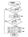
コマンド解析部6は割込パケット中のコマンドA3が割込コマンドを含むと判定するので(S67)、この判定結果に応じて割込処理実行部26はI/F95を介して機能実現部39に、機能部98で現在実行中の処理を中断してコマンドA3と内容A4に従う新たな処理を開始する旨指示を与える(S68)。CPU91はこの指示を受けて、機能部98に対し現在実行中の処理に割込をかけて中断させ、コマンドA3と内容A4に従う新たな処理を開始させる(S69)。
Since the
これにより、たとえばTV31ではTV放送の画面表示が強制的に中断されて、割込パケット中の画像データが表示開始される。 Thereby, for example, the TV 31 screen display of the TV broadcast is forcibly interrupted, and the display of the image data in the interrupt packet is started.
このように実施例7では各家電機器において割込パケットが送受信されることにより、制御対象となる家電機器において実行中の処理にユーザの要求に応じて割込をかけて中断させ、ユーザの所望する新たな処理を優先的に実行させることができる。 As described above, in the seventh embodiment, the transmission and reception of the interrupt packet in each of the home electric appliances interrupts the processing being executed in the electric home appliance to be controlled according to the request of the user, and interrupts the processing. Can be preferentially executed.
(実施例8)
図37はこの発明の実施の形態の実施例8における図2の通信制御部38のシステム構成図である。
(Example 8)
FIG. 37 is a system configuration diagram of the
図37のシステム構成と図29のそれとを比較して異なる点は、制御パケットを生成する制御パケット生成部13c、ビジー解除パケット生成部27およびビジー解除判定部28を追加している点にある。図37のその他の部分は図27のそれと同じであり説明は省略する。
The difference between the system configuration of FIG. 37 and that of FIG. 29 is that a control packet generation unit 13c for generating a control packet, a busy release
ビジー解除判定部28はI/F95を介して機能実現部39から与えられるビジー解除データBRに基づいてビジー状態が解除されたか否か判定する。機能実現部39のCPU91は機能部98の状態を監視して、ビジー状態が解除されたことを判定すると、応じてI/F95を介して通信制御部38にビジー解除データBRを出力する。
The busy
ビジー解除パケット生成部27は、ビジー解除判定部28によりビジー状態が解除されたと判定されたことに応答してビジー解除パケットを生成し送信バッファ2に格納する。
The busy release
図38はこの発明の実施の形態の実施例8における各家電機器のビジーパケット送信後のビジー状態解除の判定に関する処理フローチャートである。 FIG. 38 is a processing flowchart relating to determination of release of a busy state after transmission of a busy packet of each home electric appliance in Example 8 of the embodiment of the present invention.
図39はこの発明の実施の形態の実施例8における各家電機器のビジー解除パケットの受信に応じた処理フローチャートである。 FIG. 39 is a flowchart of a process according to the eighth embodiment of the present invention in response to the reception of the busy release packet of each household electric device.
図40はこの発明の実施の形態の実施例8におけるビジー解除パケットの一例を示す図である。 FIG. 40 is a diagram showing an example of the busy release packet according to the eighth embodiment of the present invention.
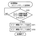
図38において、たとえばTV31においてビジーパケット受信後は、ビジー解除判定部28が対応の機能実現部39でビジー状態が解除されたか否かをビジー解除データBRが与えられるか否かにより判定する(S70)。ビジー状態が解除されたことが判定されると、応じてビジー解除パケット生成部27は図40のビジー解除パケットを生成する(S71)。図40のビジー解除パケットにはコマンドA3としてビジー状態の解除を示すコマンドが格納される。
In FIG. 38, for example, after the busy packet is received by the TV 31, the busy
生成されたビジー解除パケットはビジーパケットを送信したVCR36宛に送信バッファ2を介して送信される(S72)。
The generated busy release packet is transmitted to the
図39を参照して、VCR36は受信バッファ3を介してTV31から送信されたビジー解除パケットを受信する。受信されたビジー解除パケットについて図10のS1〜S3およびS5の処理が行なわれて、コマンド解析部6は受信パケット中のコマンドA3がビジー解除コマンドであることを判別する(S73)。この判別結果に応じて、制御パケット生成部13cは予め与えられた制御コマンドを格納したTV31宛の制御パケットを生成する(S74)。生成された制御パケットは送信バッファ2を介して送信されてTV31により受信される(S75)。
Referring to FIG. 39,
実施例8では各家電機器は他の家電機器から制御パケットにより制御の指示を受けた場合にビジー状態であったときは、その後ビジー状態が解除されるとビジー解除パケットを他の家電機器に送信する。したがって各家電機器では他の家電機器がビジー状態に有るか否かを把握するための送信処理、たとえば同じ制御パケットを繰返して他の家電機器に送信するなどの処理をしなくても容易に他の家電機器の状態を把握できる。 In the eighth embodiment, when each home electric device is in a busy state when receiving a control instruction from another home electric device by a control packet, when the busy state is released thereafter, a busy release packet is transmitted to the other home electric device. I do. Accordingly, each home appliance can easily perform other transmission processing without grasping whether or not the other home appliance is busy, for example, without repeating the same control packet and transmitting the same control packet to other home appliances. The status of home appliances.
上述した実施例1〜8によれば、たとえばVCR36を操作するだけで、家庭内の各家電機器について機能とコンテンツデータの問合せができる。また、各家電機器が有する機能を伝送路37に接続されたすべての家電機器で共有できるので、表示機能のない冷蔵庫35がTV31の画面を利用して設定された庫内温度の表示を行なうことができる。また、電子レンジ34が冷蔵庫35の庫内温度に基づいて食品を解凍するための加熱時間を調整することができる。
According to the above-described first to eighth embodiments, for example, only by operating the
9,9a 機能検索部、10 機能格納部、11,11a コンテンツ検索部、12 コンテンツ格納部、13,13a,13b 制御パケット生成部、14 パケット生成部、15,15a 入力部、16,16a 出力部、17 情報識別子格納部、18,18a 機器選択部、19 能力レベル格納部、20 優先順位設定部、21 優先順位格納部、22 ビジー状態判定部、23 ビジー理由格納部、24 ビジーパケット生成部、25 割込パケット生成部、26 割込処理実行部、27 ビジー解除パケット生成部、28 ビジー解除判定部、37 伝送路、38 通信制御部、39 機能実現部、98 機能部。 9, 9a function search unit, 10 function storage unit, 11, 11a content search unit, 12 content storage unit, 13, 13a, 13b control packet generation unit, 14 packet generation unit, 15, 15a input unit, 16, 16a output unit , 17 information identifier storage unit, 18, 18a device selection unit, 19 capability level storage unit, 20 priority order setting unit, 21 priority order storage unit, 22 busy state determination unit, 23 busy reason storage unit, 24 busy packet generation unit, 25 interrupt packet generation unit, 26 interrupt processing execution unit, 27 busy release packet generation unit, 28 busy release determination unit, 37 transmission path, 38 communication control unit, 39 function realization unit, 98 function unit.
Claims (15)
前記通信部は対応する前記機能部の前記1つ以上の機能に関連する複数の機能情報を格納する機能情報格納部を有し、
前記通信方法は前記通信部において、
前記パケットを用いて前記複数の機器のそれぞれに、前記機能情報格納部に格納された前記複数の機能情報を問合せることを特徴とする、通信方法。 A plurality of devices that transmit and receive packets, process the packets, and communicate with each other. Each of the plurality of devices implements a communication unit that implements a communication function for the communication and one or more functions different from the communication function. A communication method in a communication system having a functional unit that performs
The communication unit has a function information storage unit that stores a plurality of function information related to the one or more functions of the corresponding function unit,
The communication method may include:
A communication method, characterized by inquiring each of the plurality of devices about the plurality of function information stored in the function information storage unit using the packet.
前記通信方法は前記通信部において、
前記複数機器のそれぞれに前記命令情報および前記関連情報として前記複数の機能情報中に所定の機能情報を有しているかの問合せが格納された前記パケットを送信する問合せパケット送信ステップと、
前記問合せパケット送信ステップにより送信された前記パケットを受信したことに応じて、前記機能情報格納部中に問合せられた前記所定機能情報を有しているか否かを示す応答が前記命令情報および前記関連情報として格納された前記パケットを送信する応答パケット送信ステップとを備えた、請求項1に記載の通信方法。 The packet includes source information for uniquely specifying the device that is the source of the packet, destination information for uniquely specifying the device that is the destination of the packet, and one or more of the functional units. Command information for realizing any of the functions or the communication function and related information related to the command information are stored,
The communication method may include:
An inquiry packet transmitting step of transmitting the packet in which an inquiry as to whether or not the plurality of function information has predetermined function information as the instruction information and the related information is stored in each of the plurality of devices,
In response to receiving the packet transmitted in the inquiry packet transmitting step, a response indicating whether or not the predetermined function information has been queried in the function information storage is sent to the command information and the related information. A response packet transmitting step of transmitting the packet stored as information.
前記送信先情報として前記複数の機能情報のいずれかが格納された前記パケットを送信する送信ステップと、
前記送信ステップにより送信された前記パケットを受信して、受信パケット中の前記送信先情報が前記機能情報格納部の前記複数の機能情報のいずれかに一致するか否か判定する判定ステップと、
前記判定ステップの一致するとの判定結果に応じて、該受信パケット中の前記命令情報および前記関連情報に従って処理を実行する処理実行ステップとをさらに備えた、請求項2に記載の通信方法。 The communication method may include:
Transmitting the packet in which any of the plurality of function information is stored as the transmission destination information,
Receiving the packet transmitted by the transmitting step, determining whether the destination information in the received packet matches any of the plurality of function information of the function information storage unit,
The communication method according to claim 2, further comprising: a process execution step of executing a process according to the instruction information and the related information in the received packet in accordance with a result of the determination that the determination step matches.
前記複数の機能情報のそれぞれに対応して該機能情報の認識を容易とするための識別情報が格納される識別情報格納部と、
第1出力部とをさらに備え、
前記応答パケット送信ステップは、
前記問合せパケット送信ステップにより送信された前記パケットを受信したことに応じて、問合せられた前記所定機能情報に対応する前記識別情報格納部中の前記識別情報が、前記関連情報として格納された前記パケットを送信する識別情報応答パケット送信ステップをさらに含み、
前記通信方法は前記通信部において、
前記識別情報応答パケット送信ステップにより送信された前記パケットを受信して前記第1出力部に該受信パケットの内容を出力して報知する第1出力ステップをさらに備える、請求項2または3に記載の通信方法。 The communication unit,
An identification information storage unit storing identification information for facilitating recognition of the function information corresponding to each of the plurality of function information;
A first output unit,
The response packet transmitting step includes:
In response to receiving the packet transmitted in the inquiry packet transmitting step, the identification information in the identification information storage unit corresponding to the queried predetermined function information, the packet stored as the related information Transmitting an identification information response packet for transmitting
The communication method may include:
4. The method according to claim 2, further comprising a first output step of receiving the packet transmitted in the identification information response packet transmitting step, outputting the content of the received packet to the first output unit, and notifying the first output unit. 5. Communication method.
外部からデータを入力するための第1入力部をさらに備え、
前記通信方法は前記通信部において、
前記第1出力部により報知された内容に従って、前記第1入力部から入力されたデータを用いて前記パケットを生成し送信するパケット生成送信ステップをさらに備える、請求項4に記載の通信方法。 The communication unit,
A first input unit for inputting data from outside;
The communication method may include:
The communication method according to claim 4, further comprising a packet generation / transmission step of generating and transmitting the packet using data input from the first input unit in accordance with the content notified by the first output unit.
前記機能特定情報のそれぞれに対応し、前記複数の機器における同一の該機能特定情報に対応の機能の実現時の相対的な能力レベルを示す能力情報が格納される能力情報格納部をさらに有し、
前記応答パケット送信ステップは、
前記問合せパケット送信ステップにより送信された前記パケットを受信したことに応じて、問合せられた所定の機能特定情報に対応する前記能力情報格納部中の前記能力情報が、前記関連情報として格納された前記パケットを生成して送信する能力情報応答パケット送信ステップをさらに含み、
前記通信方法は前記通信部において、
前記能力情報応答パケット送信ステップにより送信された前記パケットを受信して、該受信パケット中の前記能力情報に基づき前記複数の機器のうち特定の機器を選択する第1機器選択ステップと、
前記送信先情報として前記第1機器選択ステップにより選択された機器を指定する情報を格納した前記パケットを生成し送信する第1送信ステップとをさらに備えた、請求項6に記載の通信方法。 The communication unit,
A capability information storage unit that stores capability information corresponding to each of the function specification information and that indicates a relative capability level when the function corresponding to the same function specification information in the plurality of devices is realized. ,
The response packet transmitting step includes:
In response to receiving the packet transmitted in the inquiry packet transmitting step, the capability information in the capability information storage unit corresponding to the queried predetermined function specifying information is stored as the related information. Further comprising a capability information response packet transmitting step of generating and transmitting a packet,
The communication method may include:
A first device selecting step of receiving the packet transmitted in the capability information response packet transmitting step and selecting a specific device among the plurality of devices based on the capability information in the received packet;
The communication method according to claim 6, further comprising: a first transmission step of generating and transmitting the packet storing information designating the device selected by the first device selection step as the transmission destination information.
前記機能特定情報のそれぞれに対応して、前記複数の機器における同一の該機能特定情報に対応の機能の実現時の相対的な優先順位を示す優先順位情報が格納される優先順位格納部をさらに有し、
前記応答パケット送信ステップは、
前記問合せパケット送信ステップにより送信された前記パケットを受信したことに応じて、問合せられた所定の機能特定情報に対応する前記優先順位格納部中の前記優先順位情報が前記関連情報として格納された前記パケットを生成し送信する優先順位応答パケット送信ステップをさらに含み、
前記通信方法は前記通信部において、
前記優先順位応答パケット送信ステップにより送信された前記パケットを受信して、該受信パケット中の前記優先順位情報に基づき前記複数の機器のうち特定の機器を選択する第2機器選択ステップと、
前記送信先情報として前記第2機器選択ステップにより選択された機器を指定する情報を格納した前記パケットを生成し送信する第2送信ステップとをさらに備えた、請求項6または7に記載の通信方法。 The communication unit,
A priority order storage unit for storing priority order information indicating relative priorities at the time of realization of a function corresponding to the same function identification information in the plurality of devices, corresponding to each of the function identification information; Have
The response packet transmitting step includes:
In response to receiving the packet transmitted by the inquiry packet transmitting step, the priority information in the priority storage unit corresponding to the queried predetermined function specifying information is stored as the related information. A priority response packet transmitting step of generating and transmitting a packet,
The communication method may include:
A second device selecting step of receiving the packet transmitted in the priority response packet transmitting step, and selecting a specific device among the plurality of devices based on the priority information in the received packet;
8. The communication method according to claim 6, further comprising: generating and transmitting the packet storing information specifying the device selected in the second device selection step as the transmission destination information. 9. .
第2出力部をさらに有し、
前記通信方法は前記通信部において、
前記パケットを受信して、前記機能部においては所定の機能を実現中で該受信パケット中の前記命令情報に従う機能の実現が不可能なビジー状態であるか否か判定する状態判定ステップと、
前記状態判定ステップによりビジー状態であると判定されたことに応じて、前記命令情報および前記関連情報にビジー状態であることを示すビジー情報が応答として格納された前記パケットをビジーパケットとして生成し送信するビジーパケット送信ステップと、
前記ビジーパケット送信ステップにより送信された前記ビジーパケットを受信して、受信された前記ビジーパケットの内容を前記第2出力部に出力して報知する第2出力ステップとをさらに備える、請求項2ないし8のいずれかに記載の通信方法。 The communication unit,
A second output unit,
The communication method may include:
A state determination step of receiving the packet and determining whether or not the function unit is in a busy state in which a predetermined function is being realized and a function according to the instruction information in the received packet cannot be realized;
In response to the determination of the busy state by the state determination step, generating and transmitting the packet in which the command information and the related information indicating busy information indicating the busy state are stored as a response as a busy packet Sending a busy packet to
A second output step of receiving the busy packet transmitted in the busy packet transmitting step, outputting the content of the received busy packet to the second output unit, and notifying the second output unit. 9. The communication method according to any one of items 8.
外部からデータ入力するための第2入力部をさらに備え、
前記通信方法は前記通信部において、
前記第2出力部により報知された内容に従って、前記第2入力部から入力されたデータを用いて割込パケットを生成して送信する割込パケット送信ステップと、
前記割込パケット送信ステップにより送信された前記割込パケットを受信したことに応じて、受信された前記割込パケットの内容に従った処理を前記機能部に実行させる制御ステップとをさらに備え、
前記割込パケットは、
前記送信先情報として前記ビジーパケット送信元の機器を指定する情報が格納され、前記命令情報として前記ビジー状態の要因となる前記所定機能の実現に割込をかけて中断させ、所望される機能を実現開始させるためのコマンドが格納されることを特徴とする、請求項9に記載の通信方法。 The communication unit,
A second input unit for externally inputting data;
The communication method may include:
An interrupt packet transmitting step of generating and transmitting an interrupt packet using data input from the second input unit according to the content notified by the second output unit;
A control step of causing the functional unit to execute a process according to the content of the received interrupt packet in response to receiving the interrupt packet transmitted by the interrupt packet transmitting step,
The interrupt packet is
Information specifying the device of the busy packet transmission source is stored as the transmission destination information, and interrupting and interrupting the realization of the predetermined function that causes the busy state as the command information, The communication method according to claim 9, wherein a command for starting realization is stored.
前記機能部では前記ビジー状態が解除されたか否か判定するビジー解除判定ステップと、
ビジー解除判定ステップにより前記ビジー状態が解除されたと判定されたことに応じて、前記送信先情報として前記ビジーパケット送信元の前記機器を指定する情報が、前記命令情報としてビジー解除された旨のコマンドがそれぞれ格納された前記パケットを生成し送信するビジー解除パケット送信ステップとをさらに備えた、請求項9または10に記載の通信方法。 The communication method may include:
A busy release determination step of determining whether the busy state has been released by the functional unit;
In response to the busy release determining step determining that the busy state has been released, information specifying the device of the busy packet transmission source as the destination information is a command indicating that the busy has been released as the command information. The communication method according to claim 9, further comprising: transmitting a busy cancellation packet for generating and transmitting the stored packet.
前記通信部は対応する前記機能部の前記1つ以上の機能に関連する複数の機能情報を格納する機能情報格納部を有し、
前記パケットを用いて前記複数の機器のそれぞれに、前記機能情報格納部に格納された前記複数の機能情報を問合せることを特徴とする、通信システム。 A plurality of devices that transmit and receive packets, process the packets, and communicate with each other. Each of the plurality of devices implements a communication unit that implements a communication function for the communication and one or more functions different from the communication function. A communication unit comprising:
The communication unit has a function information storage unit that stores a plurality of function information related to the one or more functions of the corresponding function unit,
A communication system comprising: inquiring each of the plurality of devices about the plurality of function information stored in the function information storage unit using the packet.
前記通信部は、
前記複数機器のそれぞれに前記命令情報および前記内容として前記複数の機能情報中に所定の機能情報を有しているかの問合せが格納された前記パケットを送信する問合せパケット送信手段と、
前記問合せパケット送信手段により送信された前記パケットを受信したことに応じて、前記機能情報格納部中に問合せられた前記所定機能情報を有しているか否かを示す応答が前記命令情報および前記関連情報として格納された前記パケットを送信する応答パケット送信手段とを備えた、請求項12に記載の通信システム。 The packet includes source information for uniquely specifying the device that is the source of the packet, destination information for uniquely specifying the device that is the destination of the packet, and one or more of the functional units. Command information for realizing any of the functions or the communication function and related information related to the command information are stored,
The communication unit,
Inquiry packet transmitting means for transmitting the packet in which an inquiry as to whether or not the plurality of function information has predetermined function information as the instruction information and the content is stored in each of the plurality of devices,
In response to receiving the packet transmitted by the inquiry packet transmitting unit, a response indicating whether or not the function information storage unit has the predetermined function information queried is included in the command information and the related information. The communication system according to claim 12, further comprising: a response packet transmitting unit that transmits the packet stored as information.
前記送信先情報として前記複数の機能情報のいずれかが格納された前記パケットを送信する送信手段と、
前記送信手段により送信された前記パケットを受信して、受信パケット中の前記送信先情報が前記機能情報格納部の前記複数の機能情報のいずれかに一致するか否か判定する判定手段と、
前記判定手段の一致するとの判定結果に応じて、該受信パケット中の前記命令情報および前記関連情報に従って処理を実行する処理実行手段とをさらに備えた、請求項13に記載の通信システム。 The communication unit,
Transmission means for transmitting the packet in which any of the plurality of function information is stored as the transmission destination information,
A receiving unit that receives the packet transmitted by the transmitting unit, and determines whether the destination information in the received packet matches any of the plurality of pieces of function information in the function information storage unit;
14. The communication system according to claim 13, further comprising: a process execution unit that executes a process according to the instruction information and the related information in the received packet in accordance with a determination result that the determination unit matches.
前記通信部は対応する前記機能部の前記1つ以上の機能に関連する複数の機能情報を格納する機能情報格納部を有し、
前記通信方法は前記通信部において、前記パケットを用いて前記複数の機器のそれぞれに、前記機能情報格納部に格納された前記複数の機能情報を問合せることを特徴とする、通信方法をコンピュータに実行させるための通信プログラムを記録したコンピュータで読取可能な記録媒体。 A plurality of devices that transmit and receive packets, process the packets, and communicate with each other, each of the plurality of devices realizing one or more functions different from the communication function and a communication unit that realizes a plurality of functions for the communication A computer-readable recording medium that records a communication program for causing a computer to execute a communication method in a communication system having a functional unit that performs
The communication unit has a function information storage unit that stores a plurality of function information related to the one or more functions of the corresponding function unit,
The communication method, wherein the communication unit inquires each of the plurality of devices using the packet about the plurality of function information stored in the function information storage unit. A computer-readable recording medium on which a communication program for causing a computer to execute is recorded.
Priority Applications (1)
| Application Number | Priority Date | Filing Date | Title |
|---|---|---|---|
| JP2004155988A JP2004348748A (en) | 1997-01-10 | 2004-05-26 | Computer readable recording medium having method, system and program of communication recorded thereon |
Applications Claiming Priority (2)
| Application Number | Priority Date | Filing Date | Title |
|---|---|---|---|
| JP271997 | 1997-01-10 | ||
| JP2004155988A JP2004348748A (en) | 1997-01-10 | 2004-05-26 | Computer readable recording medium having method, system and program of communication recorded thereon |
Related Parent Applications (1)
| Application Number | Title | Priority Date | Filing Date |
|---|---|---|---|
| JP33165497A Division JP3586548B2 (en) | 1997-01-10 | 1997-12-02 | Communication method, communication system, computer-readable recording medium storing communication program, and communication device |
Publications (1)
| Publication Number | Publication Date |
|---|---|
| JP2004348748A true JP2004348748A (en) | 2004-12-09 |
Family
ID=33542720
Family Applications (1)
| Application Number | Title | Priority Date | Filing Date |
|---|---|---|---|
| JP2004155988A Withdrawn JP2004348748A (en) | 1997-01-10 | 2004-05-26 | Computer readable recording medium having method, system and program of communication recorded thereon |
Country Status (1)
| Country | Link |
|---|---|
| JP (1) | JP2004348748A (en) |
Cited By (3)
| Publication number | Priority date | Publication date | Assignee | Title |
|---|---|---|---|---|
| JP2013206222A (en) * | 2012-03-29 | 2013-10-07 | Nikon Corp | Electronic device and program |
| JP2018152778A (en) * | 2017-03-14 | 2018-09-27 | 日本放送協会 | Terminal device and program |
| JP2019071095A (en) * | 2013-07-31 | 2019-05-09 | ソニー株式会社 | Information processor and information processing method |
-
2004
- 2004-05-26 JP JP2004155988A patent/JP2004348748A/en not_active Withdrawn
Cited By (5)
| Publication number | Priority date | Publication date | Assignee | Title |
|---|---|---|---|---|
| JP2013206222A (en) * | 2012-03-29 | 2013-10-07 | Nikon Corp | Electronic device and program |
| JP2019071095A (en) * | 2013-07-31 | 2019-05-09 | ソニー株式会社 | Information processor and information processing method |
| US10587466B2 (en) | 2013-07-31 | 2020-03-10 | Sony Corporation | Information processing apparatus, information processing method, program, and information processing system |
| US11329873B2 (en) | 2013-07-31 | 2022-05-10 | Sony Corporation | Information processing apparatus, information processing method, program, and information processing system |
| JP2018152778A (en) * | 2017-03-14 | 2018-09-27 | 日本放送協会 | Terminal device and program |
Similar Documents
| Publication | Publication Date | Title |
|---|---|---|
| JP3586548B2 (en) | Communication method, communication system, computer-readable recording medium storing communication program, and communication device | |
| US7032018B2 (en) | Home appliance networking system and method for controlling the same | |
| KR100638029B1 (en) | Device for network | |
| US7564804B2 (en) | Method of assigning addresses to a plurality of devices on a network and a network system therefor | |
| US6925360B2 (en) | Air conditioner control system using a telephone network and method for operating the same | |
| US7483960B2 (en) | System and method for providing a service to a terminal having data format specifications | |
| US20030100962A1 (en) | Appliance control system and method using mobile communications terminal, and home gateway | |
| JP4564249B2 (en) | Home appliance remote control system, service providing server, home server, home appliance, home appliance remote control supporting method for service providing server, and home appliance service providing support method for service providing server | |
| KR20040005598A (en) | Domestic electrification appliance and apparatus, method, program for controlling the same | |
| USRE43069E1 (en) | Method for controlling home network system | |
| US7428574B2 (en) | Device cooperation service system and electronic devices included in the system | |
| US7729282B2 (en) | Home network system and its configuration system | |
| US20050197989A1 (en) | Controller, program product, and storage medium | |
| EP2840741B1 (en) | Method and apparatus for using service of home network device based on remote access | |
| CN102610251B (en) | Information processor, playback control method and content reproduction system | |
| KR20030057298A (en) | Network device, network connection management device, and method of installing more network device | |
| CN111161522B (en) | Method for processing remote control data, storage medium, computer device and remote control system | |
| CN109974206B (en) | Air conditioning system, control method thereof, control terminal and storage medium | |
| KR100786424B1 (en) | Home electric appliances remote control system, service provision server, home server, home electric appliances remote control support method of service provision server, and home electric appliances service provision support method of service provision server | |
| EP1478128B1 (en) | Apparatus and method for connecting separate networks | |
| EP1447941A2 (en) | Home network system and method of providing operation history for same | |
| JP2004348748A (en) | Computer readable recording medium having method, system and program of communication recorded thereon | |
| JP2003308264A (en) | Network equipment and method for controlling network equipment | |
| CN113132958B (en) | Fusion networking method, device, system and computer readable storage medium | |
| JP2001069691A (en) | Power supply control system for electrical machinery and apparatus |
Legal Events
| Date | Code | Title | Description |
|---|---|---|---|
| A300 | Application deemed to be withdrawn because no request for examination was validly filed |
Free format text: JAPANESE INTERMEDIATE CODE: A300 Effective date: 20050301 |