JP2004348060A - Full color image forming apparatus and intermediate transfer body cleaning method - Google Patents
Full color image forming apparatus and intermediate transfer body cleaning method Download PDFInfo
- Publication number
- JP2004348060A JP2004348060A JP2003147779A JP2003147779A JP2004348060A JP 2004348060 A JP2004348060 A JP 2004348060A JP 2003147779 A JP2003147779 A JP 2003147779A JP 2003147779 A JP2003147779 A JP 2003147779A JP 2004348060 A JP2004348060 A JP 2004348060A
- Authority
- JP
- Japan
- Prior art keywords
- intermediate transfer
- forming apparatus
- image forming
- full
- toner
- Prior art date
- Legal status (The legal status is an assumption and is not a legal conclusion. Google has not performed a legal analysis and makes no representation as to the accuracy of the status listed.)
- Pending
Links
Images


Abstract
Description
【0001】
【発明の属する技術分野】
本発明は、複写機、プリンタ、ファクシミリ等の電子写真方式を用いたカラー画像形成装置およびその中間転写体クリーニング方法に関するものである。
【0002】
【従来の技術】
従来のカラー画像形成装置では、第1の像担持体(以下感光体)上に形成されたトナー画像を紙などの第2の像担持体(以下転写材)に転写し、その後転写材上のトナー画像を定着器によって加熱圧着を行い定着させるものが知られている(例えば、特許文献1ないし5参照)。
また、フルカラー画像を形成する従来の画像形成装置としては、転写材を転写ドラムなどの転写材担持体に保持させた状態で、感光体に現像されたイエロー、マゼンタ、シアン、ブラックの各色を転写材担持体上の転写材に順次転写し、その後、転写材担持体から剥離させた転写材を定着器によって加熱圧着を行い定着し、フルカラー画像を得るものが公知である。
一方、トナー画像を転写材担持体上の転写材に転写するのではなく、例えば特許文献1に開示されるように、感光体に現像されたイエロー、マゼンタ、シアン、ブラックの各色を中間転写体上に順次重ね合わせ(以下、一次転写と呼ぶ)、中間転写体上に形成された4色のトナー画像を転写材に一括転写(以下、二次転写と呼ぶ)した後、定着器によって定着する画像形成装置も市場にて流通し始めている。
上述のカラー画像形成装置の特徴は、転写材を従来の画像形成装置のように転写材担持体に保持させる必要が無いため、薄紙(40g/m2)や厚紙(200g/m2)、はがき、封筒などさまざまな種類の転写材に転写可能であり、転写材の汎用性が高いという利点を有する。
【特許文献1】特開平5−11562号公報
【特許文献2】特許第3267507号
【特許文献3】特開2001−222169公報
【特許文献4】特開2000−284606公報
【特許文献5】特開平5−303310号公報
【0003】
【発明が解決しようとする課題】
しかしながら、前述した中間転写体を用いた画像形成装置には次のような問題点があった。即ち、前述した中間転写体を用いた画像形成時において、前記中間転写体に形成されたトナー像は二次転写手段によって第2の像担持体(以下転写材と呼ぶ)に転移される。この時、転写材に転移しきれず中間転写体上に残った転写残トナーを除去する必要がある。この転写残トナーを除去する方法としては、特許文献5において中間転写体に弾性体からなるクリーニングブレードを当接させ転写残トナーを掻き取る方法が提案されている。
しかしながら、この方法ではブレードの当接時または離間時の摩擦抵抗変動が駆動に与える影響により中間転写体の回動に変動をきたすため、色ずれやバンディングの発生原因となる。
また、クリーニングブレードによるビビリ音の発生等の異音が問題となることもある。これは摩擦係数の上昇する高温高湿環境下で顕著である。さらに、長期間の使用においては中間転写体の表層削れという問題も生じる可能性がある。
このような課題を解決するための1つのクリーニング方法として、例えば、既述の特許文献1および特許文献4における技術が提案されている。このクリーニング方法は残トナー帯電手段によって中間転写体上の残トナーの極性を正規の帯電極性と反対の極性になるように帯電を行なう。その後一次転写にて感光体に転移させ、感光体側に設けられたクリーニング手段によって回収する。
また、残トナーが正規の帯電極性と同極性に帯電する残トナー帯電手段を設け、その下流側に設けた正規の帯電極性と逆極性のバイアスを印加した残トナー回収手段によって残トナーの回収を行なうクリーニング方法が、例えば特許文献3によって提案されている。
【0004】
しかしながら、これらの方法を用いた場合においても次のような問題点があった。即ち、二次転写残トナー量が多く、かつ帯電極性が正規の帯電極性(例えばマイナス極性)の逆極性(例えばプラス極性)の割合が多い場合には、一次転写部での感光体への転移量も多くなり、感光体から中間転写体への正規の転写工程が阻害されることがある。
この現象がひどくなると、感光体から転移するトナー画像の形状が正規の転写トナーにネガ状の抜けを生じさせる、所謂ネガ残像となってしまう。ブレードで擦り取るように中間転写体上の紙粉等の異物を取り除くことができないため、一次転写部の圧力によって感光体を傷付けることがある。
中間転写体から感光体に転移される二次転写残トナーと、感光体上の一次転写残トナーの両方を感光体クリーニングブレードによって掻き取らなければならず、感光体クリーニングブレードの損傷による寿命低下が起こり得る。
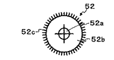
図8は残トナー帯電手段として回転ブラシを使用した従来例を示す概略断面図である。残トナー帯電手段として図8に示す回転ブラシ52を用いた場合、毛先同士の間隔が開いてしまい、残トナーとの接触機会が不十分となることでクリーニング不良が起こる。
また、残トナー帯電手段に付着したトナーを再度中間転写体に戻すための吐き出し工程が余分に必要となる。
そこで本発明の目的は、上記の問題点を解決するために、高寿命で高品質のフルカラー画像形成装置およびその中間転写体クリーニング方法を提供することにある。
【0005】
【課題を解決するための手段】
上記目的を達成するため、請求項1記載の発明は、第1の像担持体上に形成されたトナー像を中間転写体上に一次転写し、前記中間転写体上のトナー像を第2の像担持体に二次転写し、前記中間転写体に接触し二次転写後の前記中間転写体上の残トナー像を正規の帯電極性の逆極性に帯電させ、前記逆極性に帯電させた残トナーが一次転写部位を通過するさいに前記第1の像担持体に転移させて前記中間転写体のクリーニングを行なうフルカラー画像形成装置において、残トナーを帯電させる残トナー帯電手段が弾性層を有し、その表面に導電性繊維を設けたフルカラー画像形成装置を最も主要なことを特徴とする。
請求項2記載の発明は、前記弾性層が発泡体である請求項1記載のフルカラー画像形成装置を主要な特徴とする。
請求項3記載の発明は、前記導電性繊維が前記弾性層の表面にブラシ状に配設される請求項1ないし2のいずれか1項記載のフルカラー画像形成装置を主要な特徴とする。
請求項4記載の発明は、前記導電性繊維が前記弾性層表面に静電的に吸着され、予め前記弾性層表面に塗布された接着剤により固定される請求項1ないし3のいずれか1項記載のフルカラー画像形成装置を主要なことを特徴とする。
請求項5記載の発明は、前記弾性層の硬度がアスカーCで10度以上70度以下である請求項ないし4のいずれか1項記載のフルカラー画像形成装置を主要な特徴とする。
請求項6記載の発明は、前記残トナー帯電手段の抵抗値が104〜1010Ωの範囲である請求項1ないし5のいずれか1項記載のフルカラー画像形成装置を主要な特徴とする。
請求項7記載の発明は、前記残トナー帯電手段が回転体である請求項ないし6のいずれか1項記載のフルカラー画像形成装置を主要な特徴とする。
請求項8記載の発明は、前記導電性繊維の長さが0.3〜10mmの範囲である請求項1ないし7のいずれか1項記載のフルカラー画像形成装置を主要な特徴とする。
請求項9記載の発明は、前記導電性繊維の太さが0.1〜15デシテックの範囲である請求項1ないし8のいずれか1項記載のフルカラー画像形成装置を主要な特徴とする。
請求項10記載の発明は、第1の像担持体上に形成されたトナー像を中間転写体上に一次転写し、前記中間転写体上のトナー像を第2の像担持体に二次転写し、前記中間転写体に接触し二次転写後の前記中間転写体上の残トナー像を正規の帯電極性の逆極性に帯電させ、前記逆極性に帯電させた残トナーが一次転写部位を通過するさいに前記第1の像担持体に転移させて前記中間転写体のクリーニングを行なうフルカラー画像形成装置中間転写体クリーニング方法において、前記残トナー帯電手段が弾性層を有し、その表面に導電性繊維を設けたフルカラー画像形成装置の中間転写体クリーニング方法を最も主要な特徴とする。
【0006】
【発明の実施の形態】
以下、図面により本発明の実施の形態を詳細に説明する。図1は中間転写体を中間転写ベルトとした本発明のフルカラー画像形成装置の全体構成を示す概略断面図である。
図1に符号1で総括的に示されるフルカラー画像形成装置の感光体ベルトユニット10において、感光体ベルト11は矢印Aの方向に回転するように駆動ローラ14および従動ローラ15、16により張架されている。
この感光体ベルト11の近傍には感光体クリーニングユニット12、 帯電器13、露光手段20、中間転写ベルトユニット40などが配置されている。現像手段30はイエロー現像器31Y、マゼンタ現像器31M、シアン現像器31C、 ブラック現像器31Kの4個の現像器から構成されている。
フルカラー画像形成時は、イエロー現像器31Y、マゼンタ現像器31M、シアン現像器31C、ブラック現像器31Kの順で可視像を形成し、各色の可視像が中間転写ベルト41に順次重ね転写(以下、一次転写と呼ぶ)されることでフルカラー画像が形成される。
中間転写ベルト41は、駆動ローラ44、一次転写バイアスローラ45、そして従動ローラ46および47により張架されており、図示しない駆動モータによって駆動されるようになっている。
中間転写ベルト41の端部にはベルト位置検出マーク49が設けられている。マークセンサ43によってマークが検出されたタイミングで各色の画像形成プロセスを開始することにより、各色画像の正確な色重ねが可能となる。
【0007】
ところで、中間転写ベルト41に用いる材質としては、PVDF(ポリフッ化ビニリデン)、ETFE(エチレン−四フッ化エチレン共重合体)、PI(ポリイミド)、PC(ポリカーボネート)等にカーボンブラック等の導電性材料を分散させ樹脂フィルム状のエンドレスベルトとしたものを用いることができる。なお、必要に応じ中間転写ベルト41の表面に離型層をコートしても良い。
コートに用いる材料としては、ETFE(エチレン−四フッ化エチレン共重合体)、PTFE(ポリ四フッ化エチレン)、PVDF(ポリフッ化ビニリデン)、PEA(パ−フルオロアルコキシフッ素樹脂)、FEP(四フッ化エチレン−六フッ化プロピレン共重合体)、PVF(フッ化ビニル)等のフッ素樹脂が使用できるが、これに限定されるものではない。
また、上述したような樹脂フィルムベルト以外に、ゴム、エラストマ等の材料を用いた弾性層を有する中間転写体を用いることも可能である。
ところで、中間転写ベルト41の体積抵抗率および表面抵抗率であるが、体積抵抗率が109〜1012Ωcm、かつ表面抵抗率が1010〜1015Ω/□の範囲であることが望ましい。
中間転写ベルト41の抵抗測定方法として、デジタル超高抵抗微少電流計(アドバンテスト社製:R8340A)にプローブ(内側電極直径50mm、リング電極内径60mm:JIS−K6911準拠)を接続した。これを用いて中間転写ベルト41の表裏に1000V(表面抵抗率は500V)の電圧を印加して放電5秒、放電10秒で測定を行なった。
二次転写ユニット50は、二次転写バイアスローラ51、およびこの二次転写バイアスローラ51を中間転写ベルト41に対して接離させる図示しない接離機構などで構成されており、転写材90の裏面に当接しバイアスを印加することで二次転写を行なう。
二次転写バイアスローラ51はSUS等の金属製芯金上に、導電性材料によって105〜1010Ωの抵抗値に調整されたウレタン等の弾性体を被覆することで構成されており、この構成のまま使用しても良いし、必要に応じてその表面にフッ素樹脂等の高離型性フィルムを被覆しても良い。
なお、高圧電源(図示せず)は極性の異なるバイアスを印加するバイアス印加手段(図示せず)と極性を制御するバイアス極性制御手段(図示せず)とから構成されている。
【0008】
転写材90は給紙ローラ81a、81b、81c、レジストローラ82によって、中間転写ベルト41面の4色重ね画像の先端部が二次転写位置に到達するタイミングに合わせて給紙される。
二次転写バイアスローラ51は駆動ギヤ(図示しない)によって駆動力が与えられており、その周速は中間転写ベルト41の周速に対して、略同一となるよう調整されている。
二次転写バイアスローラ51は通常中間転写ベルト41面から離間しているが、中間転写ベルト41面に形成された4色の重ね画像を転写材90に一括転写するときにタイミングを取って押圧され、高圧電源によって所定のバイアス電圧を印加することにより転写材90への転写を行う。
転写材90に転写された4色重ね画像は定着ユニット60で定着されたあと排紙される。複数色のカラー連続プリント時には、転写材90後端が二次転写バイアスローラ51を十分通過するタイミングでバイアス電圧がオフされ、その後次ページの中間転写ベルト41上にトナーを付着させないために、接離機構によって中間転写ベルト41より離間される。
また、単枚プリントあるいは連続プリント時の最終ページの二次転写終了時には二次転写バイアスローラ51を中間転写ベルト41面から離間させず、転写バイアスとは逆極性のクリーニングバイアス(本実施の形態では−1kV)を一定時間印加(本実施例では転写ローラ4回転相当時間)する。
さらに続けて転写バイアスと同極性のバイアス(本実施の形態では1kV)を一定時間印加(本実施の形態では転写ローラ2回転相当時間)することで、二次転写バイアスローラ51表面に付着したトナーを中間転写ベルト41に転移させ二次転写バイアスローラ51表面に付着したトナーのクリーニングを行なう。
なお、二次転写バイアスローラ51から中間転写ベルト41に転移させられたトナーは、ベルトクリーニングユニット42によって中間転写ベルト41から回収される。中間転写ベルト41に接離可能なベルトクリーニングユニット42は中間転写ベルト41に接離可能で、クリーニングローラ52、バイアスローラ53、クリーニングブレード54およびクリーニングローラ52を中間転写ベルト41に対して接離させる図示しない接離機構などで構成されている。
ここで、上述した本発明のフルカラー画像形成装置の構成を要約すれば、第1の像担持体(感光体ベルト)11と、前記第1の像担持体11の表面を帯電させる帯電手段(帯電器)13と、前記第1の像担持体11にトナー像を形成するトナー像形成手段(露光手段)20とを備えている。
また、前記第1の像担持体11上に形成されたトナー像を中間転写体(中間転写ベルト)41上に一次転写する一次転写手段(中間転写ベルトユニット)40と、第2の像担持体(転写材)90の裏面に接触し前記中間転写体41上のトナー像を前記第2の像担持体90に二次転写する二次転写手段(二次転写ユニット)50とを備えている。
さらに、前記中間転写体41に接触し二次転写後の中間転写体41上の残トナー像を正規の帯電極性の逆極性に帯電させる残トナー帯電手段(二次転写バイアスローラ)51を備え、前記逆極性に帯電させた残トナーが一次転写部位を通過するさいに第1の像担持体11に転移させることで中間転写体41のクリーニングを行なうフルカラー画像形成装置である。
【0009】
図2は本発明のフルカラー画像形成装置に使用するクリーニングローラの第1の実施の形態を示す断面図である。クリーニングローラ52は芯金52a、芯金52aの外周に均一厚に設けた弾性層52b、弾性層52bの表面に植設したブラシ毛52cによって構成されている。
芯金52aに用いる材料としては、SUS(ステンレス鋼)、SUM(快削鋼)等の金属が使用できる。本実施の形態ではSUSの材料で、その径をφ8mmに仕上げたものを用いた。
弾性層52bに用いる材料としては、ゴム、エラストマ等が使用可能であり、例えばゴム、エラストマとしては、天然ゴム、エピクロロヒドリンゴム、アクリルゴム、シリコーンゴム、フッ素ゴム、多硫化ゴム、ポリノルボルネンゴム、イソプレンゴム、スチレン−ブタジエンゴム、ブタジエンゴム、ブチルゴム等を1種類または2種類以上使用できる。
また、エチレン−プロピレンゴム、エチレン−プロピレンコポリマー、クロロプレンゴム、クロロスルホン化ポリエチレン、塩素化ポリエチレン、アクリロニトリルブタジエンゴム、ウレタンゴム等を1種類または2種類以上使用できる。本実施の形態ではウレタンゴムを発泡させ、そのアスカーC硬度を20±5度に調整したものを用いた。
弾性層52bの硬度は小さいほうが望ましい。これは、中間転写ベルト41に対して適度な圧力でブラシ毛52cを当接させるためであり、硬度が高すぎると中間転写ベルト41の表面を傷つけてしまい、長期に渡っては表面を摩耗させてしまうためである。
一方、硬度を小さくしすぎると中間転写ベルト41への当接圧が不足し、中間転写ベルト41から二次転写残トナーを掻き取る作用に不足が生じることが分かった。弾性層52bの硬度に関しては検討の結果、アスカーC硬度において10〜70度の範囲が望ましいことがわかった。
【0010】
ブラシ毛52cに用いる材料としては、ナイロン(NY)、ポリプロピレン、ポリ塩化ビニリデン、ポリエステル樹脂、ポリブチレンテレフタレート、ポリフェニレンサルファイド、フェノール樹脂、エポキシ樹脂、ポリエステルポリウレタン樹脂、ポリエチレン、ポリブタジエン、アイオノマー樹脂、ポリウレタン樹脂、シリコーン樹脂、フッ素樹脂等から1種類あるいは2種類以上を用いることができる。
また、ケトン樹脂、ポリスチレン、クロロポリスチレン、ポリ−α−メチルスチレン、スチレン−ブタジエン共重合体、スチレン−塩化ビニル共重合体、スチレン−酢酸ビニル共重合体、スチレン−マレイン酸共重合体、スチレン−アクリル酸エステル共重合体(スチレン−アクリル酸メチル共重合体、スチレン−アクリル酸エチル共重合体等から1種類あるいは2種類以上を用いることができる。
さらに、スチレン−アクリル酸ブチル共重合体、スチレン−アクリル酸オクチル共重合体及びスチレン−アクリル酸フェニル共重合体等)、スチレン−メタクリル酸エステル共重合体(スチレン−メタクリル酸メチル共重合体、スチレン−メタクリル酸エチル共重合体およびスチレン−メタクリル酸フェニル共重合体等)等から1種類あるいは2種類以上を用いることができる。
またさらに、スチレン−α−クロルアクリル酸メチル共重合体及びスチレンアクリロニトリル−アクリル酸エステル共重合体等のスチレン系樹脂(スチレンまたはスチレン置換体を含む単重合体または共重合体)、メタクリル酸メチル樹脂、メタクリル酸ブチル樹脂、アクリル酸エチル樹脂、アクリル酸ブチル樹脂、変性アクリル樹脂(シリコーン変性アクリル樹脂、塩化ビニル樹脂変性アクリル樹脂及びアクリル・ウレタン樹脂等)等から1種類あるいは2種類以上を用いることができる。
さらに、塩化ビニル樹脂、スチレン−酢酸ビニル共重合体、塩化ビニル−酢酸ビニル共重合体、ロジン変性マレイン酸樹脂、エチレン−エチルアクリレート共重合体、キシレン樹脂、ポリビニルブチラール樹脂、ポリアミド樹脂および変性ポリフェニレンオキサイド樹脂等から1種類あるいは2種類以上を用いることができる。
【0011】
本実施の形態ではナイロンに抵抗調整のためにカーボンブラックを混錬したものを用い、その太さは3.3Dtex(デシテックス:10000m当たり3.3g)、長さは2mmのものを用いた。ここで、ブラシ毛の長さについては検討の結果、0.3〜10mmの範囲で使用可能であることがわかった。
ブラシ毛の長さが0.3mmを下回るとブラシ毛自体のコシが強いため、中間転写ベルト41の表面を傷つけ易く、やがて表面を摩耗させてしまい画像に影響が出てしまう。一方、ブラシ毛の長さが10mmを上回るとブラシ毛自体が撓みやすくなるため、残トナーの掻き取り力が不十分となるため、クリーニング不良やネガ残像を発生させてしまう。
したがってブラシ毛の長さは、0.3〜10mmの範囲が望ましく、より望ましくは0.5〜8mm、更に望ましくは0.8〜6mmの範囲である。また、ブラシ毛の太さについては検討の結果、0.1〜15Dtecの範囲で使用可能であることがわかった。
ブラシ毛の太さが0.1Dtexを下回ると、ブラシ毛自体のコシが弱く残トナーの掻き取り力が不十分となるため、クリーニング不良やネガ残像を発生させてしまう。
一方、15Dtexを上回るとブラシ毛が太くコシが強くなるため、中間転写ベルト41の表面を傷つけ易く、やがて表面を摩耗させてしまい画像に影響が出てしまう。したがって、ブラシ毛の太さは、0.1〜15Dtexの範囲が望ましく、より望ましくは0.5〜10Dtex、さらに望ましくは1〜8Dtexの範囲である。
ブラシ毛52cは芯金52a、弾性層52bで構成されたローラに、ブラシ毛52cを固定するための接着剤を薄層状に塗布し、芯金52aに高電圧(20〜40KV前後)を印加することでブラシ毛52cを静電吸着させる。接着剤はとくに限定されるものではないが、クリーニングローラ52の抵抗を安定させるために導電性を有することが望ましい。
【0012】
上述したような構成のクリーニングローラ52では、ローラ表面の毛足が短くできるため毛先の間隔を狭く維持でき、中間転写ベルト41表面との接触する確率を高くできるため残トナーを効率良く掻き取ることが可能となる。
また、低硬度の弾性層を設けたことで毛先が短いにも拘わらず、中間転写ベルト41に対して十分なニップ幅を確保できるようになる。ここで、クリーニングローラ52の抵抗測定方法について説明する。
抵抗値の測定は、金属平板にクリーニングローラ52をその毛先が1mm食い込むように固定し、芯金に1KV印加したときの金属平板との間に流れた電流値から抵抗を算出した。本実施の形態のクリーニングローラ抵抗は前述した方法で5×10⁸Ωと測定されたものを用いた。
ブラシ抵抗の使用可能範囲は検討の結果、104〜1010Ωであることが分かった。クリーニングローラ52の抵抗は、前述したように104Ω以下であるときバイアスローラ53との電位差が少なくなるためトナー回収性能、すなわちクリーニングローラ52からバイアスローラ53への残トナー転移性が低下してしまう。
このようにクリーニングローラ52に残トナーが滞留してしまうとやがてブラシ毛内にトナー詰まりが発生するため、トナー掻き取りが不十分となると同時に、中間転写ベルト41に残った、掻き取れなかった残トナーへの電荷注入が十分に行なえず、感光体への転移ができなくなるためクリーニング不良が発生してしまう。
一方、クリーニングローラ52の電気抵抗値が1010Ωを超えると、前述した印加バイアスの範囲では電流不足により電荷注入が十分に行われずクリーニング不良となる。ここで、電圧を上げると電流は流れるようになるが高電圧による放電が発生し部分的にプラス帯電量の大きい、具体的には60[μC/g]以上の残トナーが発生してしまう。
このように強くプラス帯電した残トナーは中間転写ベルト41との間に静電的吸着力が強く発生し、クリーニングローラ52による掻き取りが不十分となり、また感光体ベルト11への転移ができなくなるためクリーニング不良となる。したがって、クリーニングローラ52の抵抗値範囲は104〜1010Ωであることが望ましい。
【0013】
図3はベルトクリーニングユニットの動作を説明する概略図である。このように構成されたクリーニングローラ52を用いたベルトクリーニングユニットの動作を説明する。クリーニングローラ52はフルカラー画像を形成するときは中間転写ベルト41上に4色のトナー画像が形成されるまで、接離機構によって中間転写ベルト41面から離間させられている。
クリーニングローラ52は、中間転写ベルト41上の画像が転写材90に二次転写された後の転写残トナーがベルトクリーニングユニット42に到達するタイミングに合わせ、接離機構によって中間転写ベルト41に当接する。
クリーニングローラ52は当接するタイミングに合わせ、図示しないクラッチにより回動されると同時に、バイアスローラ53には高圧電源110によってクリーニングバイアスが印加される。
クリーニングローラ52の回転方向は、図3に示すように本実施の形態では中間転写ベルト41の回転方向に対して反対方向、すなわち逆方向となるようにした。このような方向に回転するようにしたことで、十分な掻き取り力が得られる。
本実施の形態ではクリーニングバイアスとして、800Vの定電圧印加を行なった。
なお、クリーニングバイアスの検討を行なった結果、600〜1800Vの範囲で使用可能なことがわかった。ところでトナーの帯電極性は本実施の形態の場合、二次転写前まではマイナス極性であるが二次転写後の残トナー極性はプラス極性が多く含まれる。これは二次転写時の放電により極性反転するためで、二次転写バイアスを高くするとプラス極性トナーの割合も多くなる。
このようにプラス極性に帯電した残トナーが一次転写ニップ部に到達すると、一次転写バイアスにより形成された転写電界によって通常の一次転写とは逆に中間転写ベルト41から感光体ベルト11に転移する。
【0014】
しかしながら、二次転写残トナーの極性は必ずしもすべてがプラス極性ではなく、マイナス極性や帯電量が0に近いものも混在しており、残トナー帯電量を測定したところ−10〜+10[μC/g]であった。
これは転写材90の材質やその吸湿状態、二次転写が行われる雰囲気環境などによって残トナーの受ける放電状態が変化するからである。このため、前述したようにクリーニングローラ52に正極のクリーニングバイアスを印加することによって、マイナス極性の残トナーはクリーニングローラ52に吸着する。
その後クリーニングローラ52とバイアスローラ53との電位差で残トナーはバイアスローラ53に転移する。さらにバイアスローラ53に転移した残トナーはクリーニングブレード54によって掻き落とされる。
帯電量が0に近いものや、プラス極性に帯電している残トナー、さらに紙粉等の異物もクリーニングローラ52のブラシ毛先によって中間転写ベルト41から掻き取り回収され、一部はマイナス極性トナーと一緒にバイアスローラ53に転移する。
【0015】
図4はクリーニングローラから残トナーを回収するメカニズムを説明する概略図である。図4に示すように、また、クリーニングローラ52上の他の残トナーおよび紙粉等の異物については、バイアスローラ53との接点部にてブラシ毛先の跳ねによってバイアスローラ53上に飛翔転移し、クリーニングブレード54によって掻き落とされる。
上述したように中間転写ベルト41上の残トナーについては、クリーニングローラ52によってその大部分が掻き取り回収されるが、わずかながら回収されなかった中間転写ベルト41上の残トナーはクリーニングローラ52に印加されたバイアスによって、プラス極性の電荷注入が行われることで中間転写ベルト41上から感光体ベルト11に転移させられる。
本実施の形態におけるクリーニングローラ52通過後の残トナー帯電量は+20〜+40[μC/g]であった。なお、本実施例では中間転写ベルト41からクリーニングローラ52への残トナー回収率はいずれも90%以上であった。
ここで残トナー回収率の算出方法は次式、
(クリーニングローラ52回収トナー重量/中間転写ベルト41上残トナー)×100[%]
によって求めた。
本実施の形態で説明したクリーニングローラ52を画像形成装置に組み入れ、画像形成を行なったところ、クリーニング不良、ネガ残像の発生が全くない良好なフルカラー画像が得られた。
図5は本発明によるクリーニングローラの第2の実施の形態を示す概略断面図である。図5に示すように、第1の実施の形態の弾性層52bにさらに薄膜のチューブ52dを被せ、その上にブラシ毛52cを静電吸着および接着固定させクリーニングローラ52としたものである。
本実施の形態では薄膜チューブ52dとして厚み100μmのフッ素樹脂であるPFAチューブを被覆させた。このように弾性層52bの発泡材料にPFAチューブを被覆したことで、クリーニングローラ52の全体硬度は若干上がるものの、弾性層52b表面に生じた発泡によるセル穴を被うことが可能となるため、ブラシ毛52cの植毛状態にムラが生じにくい利点がある。
第2の実施の形態のクリーニングローラ52を画像形成装置に組み入れ、画像形成を行なったところ、クリーニング不良、ネガ残像の発生が全くない良好なフルカラー画像が得られた。
【0016】
図6は本発明によるクリーニングローラの第3の実施の形態を示す概略図である。本実施の形態では図6に示すように、弾性層52bの材質に発泡させないウレタンゴムを用いた。
このように弾性層52bに発泡材料を用いないようにしたことで、クリーニングローラ52の全体硬度は若干上がるものの、弾性層52b表面に発泡によるセル穴が無いため、ブラシ毛52cの植毛状態にムラが生じにくい利点がある。
本実施の形態のクリーニング不良、ネガ残像の発生が全くない良好なフルカラー画像が得られた。
図7は本発明によるクリーニングローラの第4の実施の形態のクリーニングローラの回転方向を示す概略図である。本実施の形態では図7に示すように、クリーニングローラ52の回転方向の違い以外の構成は第1の実施の形態と同じである。
本実施の形態ではクリーニングローラ52の回転方向を中間転写ベルト41の回転方向に対して同一方向となるようにした。なお、クリーニングローラ52の回転周速は掻き取り力を上げるために中間転写ベルト41よりも若干速めに設定するほうが望ましい。本実施の形態では、中間転写ベルト41の1.3倍速としたが1.1〜2倍程度まで使用可能である。
2倍以上に速くすると、クリーニングローラ52が一度掻き取った残トナーを飛散させてしまうためである。このような方向に回転するようにしたことと周速を若干速めに設定したことで、十分な掻き取り力が得られる。
本実施の形態においても、このクリーニングローラ52を画像形成装置に組み入れ、画像形成を行なったところ、クリーニング不良、ネガ残像の発生が全くない良好なフルカラー画像が得られた。
【0017】
以上説明したように、弾性層を有し、その表面にブラシ毛を接着固定させた構成のクリーニングローラを用いた画像形成装置としたことで、クリーニング不良、ネガ残像の発生が全くない良好なフルカラー画像が得られるようになった。
なお、以上説明した実施の形態は、本発明の理解を容易にするために記載されたものであって、本発明を限定するものではない。たとえば、上述した実施の形態では、クリーニングローラ52を構成する材料について例示したが、これに限定されるものではなく、適宜好適な材料を使用することが可能である。
中間転写体として中間転写ベルトを用いたが、中間転写ドラムでも構わない。また、像担持体として感光体ベルトを用いて説明したが、本発明はこれに限定されるものではなく、感光体ドラム等、すべての像担持体に適用可能である。
また、現像方式は1成分反転現像で説明したが、正規現像、さらには2成分現像にも適用可能である。さらに、二次転写手段として転写ローラを用いたが、回転型転写ブラシなどの回転型接触転写方式はもちろんのこと、転写ブラシ、転写ブレード、転写プレートなどの転写方式でも本発明を適用可能である。
さらに、一次、二次転写バイアス、クリーニングバイアスは上記説明した値に限定されることなく、適宜好適な値に設定することが可能である。
【0018】
【発明の効果】
以上説明したように、請求項1によれば、残トナー帯電手段は弾性層を有し、その表面に導電性繊維を設けたことで、残トナー帯電手段による転写残トナーの回収効率を高くできるためクリーニング不良、ネガ残像の発生が防止でき、また中間転写体の表面に適度な圧力で当接させることができるため、良好なフルカラー画像が長期に渡って得られる。
請求項2によれば、残トナー帯電手段の弾性層を発泡体としたので、低硬度化が実現でき、中間転写体の表面に適度な圧力で当接させることができるため、クリーニング不良の無い良好なフルカラー画像が長期にわたって得られる。
請求項3によれば、導電性繊維を弾性層の表面にブラシ状に配設したので、残トナー帯電手段による転写残トナーの回収効率が高くできるためクリーニング不良、ネガ残像の発生が防止でき、良好なフルカラー画像が得られる。
請求項4によれば、導電性繊維は前記残トナー帯電手段の弾性層表面に静電的に吸着され、予め弾性層表面に塗布された接着剤により固定されるので、残トナー帯電手段の表面に均一なブラシ毛の植毛と固定が可能となり、転写残トナーの回収効率が高く、クリーニング不良、ネガ残像の発生が無い、良好なフルカラー画像が得られる。
請求項5によれば、弾性層硬度はアスカーCで10度以上70度以下であるので、中間転写体の表面に適度な圧力で当接させることができるため、クリーニング不良の無い良好なフルカラー画像が長期にわたって得られる。
【0019】
請求項6によれば、残トナー帯電手段の抵抗値は104〜1010Ωの範囲であるので、クリーニング不良の無い良好なフルカラー画像が得られる。
請求項7によれば、残トナー帯電手段は回転体であるので、残トナー帯電手段による転写残トナーの回収効率が高く、クリーニング不良、ネガ残像の発生が防止でき、良好なフルカラー画像が得られる。
請求項8によれば、導電性繊維の長さは0.3〜10mmの範囲であるので、繊維の曲げクセが発生しにくく、長期に渡って転写残トナーの回収効率が高く、クリーニング不良、ネガ残像の発生が防止でき、良好なフルカラー画像が得られる。
請求項9によれば、前記導電性繊維の太さは0.1〜15Dtec(デシテックス)の範囲であるので、中間転写体の表面に適度な圧力で当接させることができ、残トナー帯電手段による転写残トナーの回収効率が高くできるためクリーニング不良、ネガ残像の発生が防止でき、また中間転写体を損傷させないため、良好なフルカラー画像が長期にわたって得られる。
請求項10によれば、残トナー帯電手段は弾性層を有し、その表面に導電性繊維を設けたことで、残トナー帯電手段による転写残トナーの回収効率を高くできるためクリーニング不良、ネガ残像の発生が防止でき、また中間転写体の表面に適度な圧力で当接させることができるため、良好なフルカラー画像が長期にわたって得られる。
【図面の簡単な説明】
【図1】中間転写体を中間転写ベルトとした本発明のフルカラー画像形成装置の全体構成を示す概略断面図。
【図2】本発明のフルカラー画像形成装置に使用するクリーニングローラの第1の実施の形態を示す断面図。
【図3】ベルトクリーニングユニットの動作を説明する概略図。
【図4】クリーニングローラから残トナーを回収するメカニズムを説明する概略図。
【図5】本発明によるクリーニングローラの第2の実施の形態を示す概略断面図。
【図6】本発明によるクリーニングローラの第3の実施の形態を示す概略図。
【図7】本発明によるクリーニングローラの第4の実施の形態のクリーニングローラの回転方向を示す概略図。
【図8】残トナー帯電手段として回転ブラシを使用した従来例を示す概略断面図。
【符号の説明】
1 フルカラー画像形成装置、11 第1の像担持体(感光体)、40 一次転写手段(中間転写ベルトユニット)、41 中間転写体(中間転写ベルト)50 二次転写手段(二次転写ユニット)、51 残トナー帯電手段(二次転写バイアスローラ)、52 クリーニングローラ、52a 芯金、52b 弾性層、52c ブラシ毛(導電性繊維)、53 バイアスローラ、90 第2の像担持体(転写材)。[0001]
TECHNICAL FIELD OF THE INVENTION
The present invention relates to a color image forming apparatus using an electrophotographic method, such as a copying machine, a printer, and a facsimile, and a method of cleaning an intermediate transfer member thereof.
[0002]
[Prior art]
In a conventional color image forming apparatus, a toner image formed on a first image carrier (hereinafter referred to as a photoconductor) is transferred to a second image carrier (hereinafter referred to as a transfer material) such as paper, and then transferred onto the transfer material. There is known a method in which a toner image is heated and pressed by a fixing device and fixed (for example, see Patent Documents 1 to 5).
In a conventional image forming apparatus for forming a full-color image, a transfer material is held on a transfer material carrier such as a transfer drum, and the developed yellow, magenta, cyan, and black colors are transferred to a photoconductor. It is known that a transfer material is sequentially transferred to a transfer material on a material carrier, and then the transfer material peeled from the transfer material carrier is heated and pressed by a fixing device and fixed to obtain a full-color image.
On the other hand, instead of transferring a toner image to a transfer material on a transfer material carrier, for example, as disclosed in Patent Document 1, each color of yellow, magenta, cyan, and black developed on a photoreceptor is transferred to an intermediate transfer member. The toner images of four colors formed on the intermediate transfer body are collectively transferred to a transfer material (hereinafter, referred to as secondary transfer), and then fixed by a fixing device. Image forming apparatuses have also begun to be distributed in the market.
The color image forming apparatus described above is characterized in that it is not necessary to hold the transfer material on the transfer material carrier unlike the conventional image forming apparatus, and therefore, the thin paper (40 g / m 2 ) And cardboard (200g / m 2 ), Postcards, envelopes, and other various types of transfer materials, and has the advantage of high versatility of the transfer material.
[Patent Document 1] JP-A-5-11562
[Patent Document 2] Japanese Patent No. 3267507
[Patent Document 3] JP-A-2001-222169
[Patent Document 4] JP-A-2000-284606
[Patent Document 5] JP-A-5-303310
[0003]
[Problems to be solved by the invention]
However, the image forming apparatus using the above-described intermediate transfer member has the following problems. That is, at the time of image formation using the above-described intermediate transfer member, the toner image formed on the intermediate transfer member is transferred to a second image carrier (hereinafter, referred to as a transfer material) by a secondary transfer unit. At this time, it is necessary to remove the transfer residual toner remaining on the intermediate transfer member without being transferred to the transfer material. As a method for removing the transfer residual toner, Patent Document 5 proposes a method in which a cleaning blade made of an elastic material is brought into contact with an intermediate transfer member to scrape off the transfer residual toner.
However, according to this method, the rotation of the intermediate transfer body varies due to the influence of the frictional resistance variation at the time of contact or separation of the blade on the driving, thereby causing color shift and banding.
In addition, abnormal noise such as generation of chattering noise due to the cleaning blade may be a problem. This is remarkable in a high-temperature and high-humidity environment where the friction coefficient increases. Further, there is a possibility that a problem of abrasion of the surface layer of the intermediate transfer member may occur in long-term use.
As one cleaning method for solving such a problem, for example, the techniques described in Patent Literature 1 and Patent Literature 4 have been proposed. In this cleaning method, charging is performed by the remaining toner charging means so that the polarity of the remaining toner on the intermediate transfer member is opposite to the normal charging polarity. Thereafter, the toner is transferred to the photoconductor by primary transfer, and is collected by a cleaning unit provided on the photoconductor.
In addition, a residual toner charging means for charging the residual toner to the same polarity as the regular charging polarity is provided, and the residual toner is collected by a residual toner collecting means provided on the downstream side to which a bias having a polarity opposite to the regular charging polarity is applied. A cleaning method to be performed is proposed in, for example, Patent Document 3.
[0004]
However, even when these methods are used, there are the following problems. That is, when the amount of the secondary transfer residual toner is large and the ratio of the charge polarity is the reverse polarity (for example, plus polarity) of the normal charge polarity (for example, minus polarity) is large, the transfer to the photoconductor at the primary transfer portion is performed. In some cases, the amount increases, and the normal transfer step from the photoconductor to the intermediate transfer body may be hindered.
If this phenomenon becomes severe, the shape of the toner image transferred from the photoconductor will cause a so-called negative afterimage, which causes the normal transfer toner to have a negative omission. Since it is not possible to remove foreign matter such as paper dust on the intermediate transfer member as if rubbing with a blade, the pressure of the primary transfer portion may damage the photoconductor.
Both the secondary transfer residual toner transferred from the intermediate transfer member to the photosensitive member and the primary transfer residual toner on the photosensitive member must be scraped off by the photosensitive member cleaning blade. It can happen.
FIG. 8 is a schematic sectional view showing a conventional example using a rotating brush as a residual toner charging means. When the rotating
Further, an extra discharge step is required to return the toner attached to the residual toner charging means to the intermediate transfer member again.
Accordingly, an object of the present invention is to provide a high quality full-color image forming apparatus with a long life and a method of cleaning an intermediate transfer member thereof in order to solve the above-mentioned problems.
[0005]
[Means for Solving the Problems]
In order to achieve the above object, according to the first aspect of the present invention, a toner image formed on a first image carrier is primarily transferred onto an intermediate transfer member, and the toner image on the intermediate transfer member is transferred to a second image carrier. The secondary transfer to an image carrier, the residual toner image on the intermediate transfer body after the secondary transfer in contact with the intermediate transfer body, is charged to the opposite polarity of the normal charging polarity, and the remaining toner image is charged to the opposite polarity. In a full-color image forming apparatus which cleans the intermediate transfer member by transferring the toner to the first image carrier when the toner passes through the primary transfer portion, the residual toner charging means for charging the residual toner has an elastic layer. The most important feature of the present invention is a full-color image forming apparatus provided with conductive fibers on its surface.
According to a second aspect of the present invention, a main feature of the full-color image forming apparatus according to the first aspect is that the elastic layer is a foam.
According to a third aspect of the present invention, there is provided a full-color image forming apparatus according to any one of the first to second aspects, wherein the conductive fibers are arranged in a brush shape on the surface of the elastic layer.
According to a fourth aspect of the present invention, the conductive fiber is electrostatically adsorbed on the surface of the elastic layer and fixed by an adhesive previously applied to the surface of the elastic layer. The full-color image forming apparatus described above is mainly characterized.
According to a fifth aspect of the invention, there is provided a full-color image forming apparatus according to any one of the first to fourth aspects, wherein the hardness of the elastic layer is 10 to 70 degrees in Asker C.
The invention according to claim 6, wherein the residual toner charging means has a resistance value of 10 4 -10 10 The main feature of the full-color image forming apparatus according to any one of claims 1 to 5, which is in the range of Ω.
According to a seventh aspect of the present invention, there is provided a full-color image forming apparatus according to any one of the first to sixth aspects, wherein the remaining toner charging unit is a rotating body.
The invention according to claim 8 is characterized mainly by the full-color image forming apparatus according to any one of claims 1 to 7, wherein the length of the conductive fiber is in the range of 0.3 to 10 mm.
According to a ninth aspect of the present invention, there is provided a full-color image forming apparatus according to any one of the first to eighth aspects, wherein a thickness of the conductive fiber is in a range of 0.1 to 15 dtex.
According to a tenth aspect of the present invention, the toner image formed on the first image carrier is primarily transferred onto an intermediate transfer member, and the toner image on the intermediate transfer member is secondarily transferred onto a second image carrier. Then, the residual toner image on the intermediate transfer member after the secondary transfer in contact with the intermediate transfer member is charged to the opposite polarity of the normal charging polarity, and the residual toner charged to the opposite polarity passes through the primary transfer portion. In a full-color image forming apparatus intermediate transfer member cleaning method in which the intermediate transfer member is cleaned by transferring to the first image carrier at the same time, the residual toner charging means has an elastic layer, and the surface thereof has a conductive property. The most important feature is a method for cleaning an intermediate transfer member of a full-color image forming apparatus provided with fibers.
[0006]
BEST MODE FOR CARRYING OUT THE INVENTION
Hereinafter, embodiments of the present invention will be described in detail with reference to the drawings. FIG. 1 is a schematic sectional view showing the entire configuration of a full-color image forming apparatus of the present invention using an intermediate transfer member as an intermediate transfer belt.
In a
In the vicinity of the photoreceptor belt 11, a photoreceptor cleaning unit 12, a
At the time of full-color image formation, a visible image is formed in the order of the yellow developing
The
A belt
[0007]
By the way, as a material used for the
Materials used for the coating include ETFE (ethylene-tetrafluoroethylene copolymer), PTFE (polytetrafluoroethylene), PVDF (polyvinylidene fluoride), PEA (perfluoroalkoxy fluororesin), and FEP (tetrafluoroethylene). Fluorinated resins such as ethylene fluoride-hexafluoropropylene copolymer) and PVF (vinyl fluoride) can be used, but are not limited thereto.
Further, in addition to the resin film belt as described above, an intermediate transfer member having an elastic layer using a material such as rubber or elastomer can be used.
Incidentally, the volume resistivity and the surface resistivity of the
As a method for measuring the resistance of the
The
The secondary
The high-voltage power supply (not shown) includes bias applying means (not shown) for applying biases having different polarities and bias polarity control means (not shown) for controlling the polarity.
[0008]
The
The secondary
The secondary
The four-color superimposed image transferred to the
Further, at the end of the secondary transfer of the last page during single-sheet printing or continuous printing, the secondary
Subsequently, by applying a bias having the same polarity as the transfer bias (1 kV in the present embodiment) for a certain period of time (equivalent to two rotations of the transfer roller in the present embodiment), the toner adhered to the surface of the secondary
The toner transferred from the secondary
Here, the configuration of the above-described full-color image forming apparatus of the present invention can be summarized as follows: a first image carrier (photoconductor belt) 11 and a charging unit (charging unit) for charging the surface of the first image carrier 11 And a toner image forming means (exposure means) 20 for forming a toner image on the first image carrier 11.
A primary transfer means (intermediate transfer belt unit) 40 for primarily transferring the toner image formed on the first image carrier 11 onto an intermediate transfer member (intermediate transfer belt) 41; and a second image carrier. A secondary transfer unit (secondary transfer unit) 50 that contacts the back surface of the (transfer material) 90 and secondary-transfers the toner image on the
Further, there is provided a residual toner charging means (secondary transfer bias roller) 51 which contacts the
[0009]
FIG. 2 is a sectional view showing a first embodiment of a cleaning roller used in the full-color image forming apparatus of the present invention. The cleaning
Metals such as SUS (stainless steel) and SUM (free-cutting steel) can be used as the material used for the cored
As a material used for the
In addition, one or more of ethylene-propylene rubber, ethylene-propylene copolymer, chloroprene rubber, chlorosulfonated polyethylene, chlorinated polyethylene, acrylonitrile butadiene rubber, and urethane rubber can be used. In the present embodiment, urethane rubber foamed and its Asker C hardness adjusted to 20 ± 5 degrees was used.
It is desirable that the hardness of the
On the other hand, it was found that if the hardness was too low, the contact pressure against the
[0010]
Materials used for the brush bristles 52c include nylon (NY), polypropylene, polyvinylidene chloride, polyester resin, polybutylene terephthalate, polyphenylene sulfide, phenol resin, epoxy resin, polyester polyurethane resin, polyethylene, polybutadiene, ionomer resin, polyurethane resin, One type or two or more types can be used from a silicone resin, a fluorine resin and the like.
Also, ketone resin, polystyrene, chloropolystyrene, poly-α-methylstyrene, styrene-butadiene copolymer, styrene-vinyl chloride copolymer, styrene-vinyl acetate copolymer, styrene-maleic acid copolymer, styrene- Acrylic ester copolymers (one or more of styrene-methyl acrylate copolymers, styrene-ethyl acrylate copolymers, etc. can be used.
Further, styrene-butyl acrylate copolymer, styrene-octyl acrylate copolymer, styrene-phenyl acrylate copolymer, etc.), styrene-methacrylate copolymer (styrene-methyl methacrylate copolymer, styrene) -Ethyl methacrylate copolymer and styrene-phenyl methacrylate copolymer) or the like.
Further, styrene resins (a homopolymer or a copolymer containing styrene or a styrene substituent) such as a styrene-α-methyl methyl acrylate copolymer and a styrene acrylonitrile-acrylate copolymer, and a methyl methacrylate resin Butyl methacrylate resin, ethyl acrylate resin, butyl acrylate resin, modified acrylic resin (silicone modified acrylic resin, vinyl chloride resin modified acrylic resin, acryl / urethane resin, etc.) and the like. it can.
Further, vinyl chloride resin, styrene-vinyl acetate copolymer, vinyl chloride-vinyl acetate copolymer, rosin-modified maleic resin, ethylene-ethyl acrylate copolymer, xylene resin, polyvinyl butyral resin, polyamide resin and modified polyphenylene oxide One type or two or more types can be used from a resin or the like.
[0011]
In the present embodiment, nylon obtained by kneading carbon black for resistance adjustment is used, and the thickness is 3.3 Dtex (decitex: 3.3 g per 10,000 m) and the length is 2 mm. Here, the length of the brush bristles was examined, and as a result, it was found that the brush bristles could be used in the range of 0.3 to 10 mm.
If the length of the brush bristles is less than 0.3 mm, the stiffness of the brush bristles themselves is so strong that the surface of the
Therefore, the length of the brush bristles is preferably in the range of 0.3 to 10 mm, more preferably 0.5 to 8 mm, and still more preferably 0.8 to 6 mm. In addition, as a result of studying the thickness of the brush bristles, it was found that the brush bristles could be used in the range of 0.1 to 15 Dtec.
When the thickness of the brush bristles is less than 0.1 Dtex, the stiffness of the brush bristles themselves is weak and the scraping force of the residual toner is insufficient, so that poor cleaning or a negative afterimage may occur.
On the other hand, if it exceeds 15 Dtex, the brush bristles become thick and stiff, so that the surface of the
The brush bristles 52c apply a thin layer of an adhesive for fixing the brush bristles 52c to a roller composed of the
[0012]
In the cleaning
Further, the provision of the low-hardness elastic layer makes it possible to secure a sufficient nip width with respect to the
In the measurement of the resistance value, the cleaning
As a result of examination, the usable range of the brush resistance was 10 4 -10 10 Ω. The resistance of the cleaning
When the residual toner accumulates on the cleaning
On the other hand, when the electric resistance value of the cleaning
The strongly positively charged residual toner generates a strong electrostatic attraction force with the
[0013]
FIG. 3 is a schematic diagram illustrating the operation of the belt cleaning unit. The operation of the belt cleaning unit using the cleaning
The cleaning
The cleaning
As shown in FIG. 3, in this embodiment, the rotation direction of the cleaning
In this embodiment, a constant voltage of 800 V is applied as a cleaning bias.
As a result of studying the cleaning bias, it was found that the cleaning bias could be used in the range of 600 to 1800V. By the way, in the case of the present embodiment, the charge polarity of the toner is negative before the secondary transfer, but the remaining toner polarity after the secondary transfer includes many positive polarities. This is because the polarity is reversed by the discharge at the time of the secondary transfer, and when the secondary transfer bias is increased, the ratio of the positive polarity toner also increases.
When the positively charged residual toner reaches the primary transfer nip portion, the toner is transferred from the
[0014]
However, the polarity of the secondary transfer residual toner is not necessarily all the positive polarity, and the negative polarity and the charge amount near 0 are mixed together. When the residual toner charge amount is measured, it is -10 to +10 [μC / g. ]Met.
This is because the discharge state of the remaining toner changes depending on the material of the
Thereafter, the residual toner is transferred to the
Those having a charge amount close to zero, residual toner charged to a positive polarity, and foreign matters such as paper powder are also scraped and collected from the
[0015]
FIG. 4 is a schematic diagram illustrating a mechanism for collecting the residual toner from the cleaning roller. As shown in FIG. 4, foreign matters such as other residual toner and paper dust on the cleaning
As described above, most of the remaining toner on the
The residual toner charge amount after passing through the cleaning
Here, the method of calculating the residual toner recovery rate is as follows:
(Weight of toner collected by cleaning
Asked by.
When the cleaning
FIG. 5 is a schematic sectional view showing a second embodiment of the cleaning roller according to the present invention. As shown in FIG. 5, a cleaning
In the present embodiment, a PFA tube made of a fluororesin having a thickness of 100 μm is coated as the
When the cleaning
[0016]
FIG. 6 is a schematic view showing a third embodiment of the cleaning roller according to the present invention. In this embodiment, as shown in FIG. 6, non-foamed urethane rubber is used as the material of the
By not using a foaming material for the
A good full-color image free from poor cleaning and negative afterimages according to the present embodiment was obtained.
FIG. 7 is a schematic diagram showing the rotation direction of the cleaning roller of the fourth embodiment of the cleaning roller according to the present invention. In the present embodiment, as shown in FIG. 7, the configuration other than the difference in the rotation direction of the cleaning
In the present embodiment, the rotation direction of the cleaning
If the speed is twice or more, the residual toner once scraped off by the cleaning
Also in the present embodiment, when the cleaning
[0017]
As described above, the image forming apparatus using the cleaning roller having the configuration in which the elastic layer is provided and the brush hairs are adhered and fixed to the surface thereof provides a good full-color image having no defective cleaning and no negative image lag. Images can now be obtained.
The embodiments described above are described to facilitate understanding of the present invention, and do not limit the present invention. For example, in the above-described embodiment, the material forming the cleaning
Although the intermediate transfer belt is used as the intermediate transfer member, an intermediate transfer drum may be used. Further, although the description has been made using the photoconductor belt as the image carrier, the present invention is not limited to this, and can be applied to all image carriers such as a photoconductor drum.
Further, the development method has been described as one-component reversal development, but the present invention can be applied to regular development and further to two-component development. Further, although the transfer roller is used as the secondary transfer means, the present invention can be applied not only to a rotary contact transfer method such as a rotary transfer brush, but also to a transfer method such as a transfer brush, a transfer blade, and a transfer plate. .
Further, the primary, secondary transfer bias, and cleaning bias are not limited to the values described above, but can be set to appropriate values as appropriate.
[0018]
【The invention's effect】
As described above, according to the first aspect, since the remaining toner charging unit has the elastic layer and the conductive fibers are provided on the surface thereof, the collection efficiency of the transfer residual toner by the remaining toner charging unit can be increased. Therefore, it is possible to prevent poor cleaning and generation of a negative afterimage, and it is possible to bring the intermediate transfer member into contact with the surface of the intermediate transfer member at an appropriate pressure, so that a good full-color image can be obtained for a long period of time.
According to the second aspect, since the elastic layer of the residual toner charging means is made of a foam, low hardness can be realized, and the intermediate transfer body can be brought into contact with the surface of the intermediate transfer body at an appropriate pressure. Good full-color images can be obtained over a long period of time.
According to the third aspect, since the conductive fibers are arranged in the shape of a brush on the surface of the elastic layer, the recovery efficiency of the transfer residual toner by the residual toner charging means can be increased, so that cleaning failure and generation of a negative afterimage can be prevented. A good full-color image can be obtained.
According to the fourth aspect, since the conductive fibers are electrostatically adsorbed on the surface of the elastic layer of the remaining toner charging means and fixed by the adhesive applied to the surface of the elastic layer in advance, the surface of the remaining toner charging means is fixed. In this way, it is possible to implant and fix the brush bristles evenly, to obtain a high transfer efficiency of the transfer residual toner, and to obtain a good full-color image free from poor cleaning and negative afterimage.
According to the fifth aspect, since the hardness of the elastic layer is 10 degrees or more and 70 degrees or less for Asker C, the intermediate layer can be brought into contact with the surface of the intermediate transfer member with an appropriate pressure. Is obtained over a long period of time.
[0019]
According to claim 6, the resistance value of the remaining toner charging means is 10 4 -10 10 Within the range of Ω, a good full-color image free from cleaning failure can be obtained.
According to the seventh aspect, since the residual toner charging unit is a rotating body, the recovery efficiency of the transfer residual toner by the residual toner charging unit is high, and poor cleaning and generation of a negative residual image can be prevented, and a good full-color image can be obtained. .
According to claim 8, since the length of the conductive fiber is in the range of 0.3 to 10 mm, bending of the fiber is hardly generated, the recovery efficiency of the transfer residual toner is high over a long period of time, Generation of a negative afterimage can be prevented, and a good full-color image can be obtained.
According to the ninth aspect, since the thickness of the conductive fiber is in the range of 0.1 to 15 Dtec (decitex), the conductive fiber can be brought into contact with the surface of the intermediate transfer member at an appropriate pressure, and the remaining toner charging unit can be used. As a result, it is possible to prevent the occurrence of poor cleaning and negative afterimages, and to prevent the intermediate transfer member from being damaged, thereby obtaining a good full-color image for a long period of time.
According to the tenth aspect, the residual toner charging unit has an elastic layer, and the conductive fibers are provided on the surface thereof, so that the efficiency of collecting the transfer residual toner by the residual toner charging unit can be increased. Can be prevented and the surface of the intermediate transfer member can be brought into contact with the surface of the intermediate transfer member at an appropriate pressure, so that a good full-color image can be obtained for a long period of time.
[Brief description of the drawings]
FIG. 1 is a schematic cross-sectional view illustrating the entire configuration of a full-color image forming apparatus of the present invention in which an intermediate transfer member is used as an intermediate transfer belt.
FIG. 2 is a cross-sectional view illustrating a first embodiment of a cleaning roller used in the full-color image forming apparatus of the present invention.
FIG. 3 is a schematic diagram illustrating the operation of the belt cleaning unit.
FIG. 4 is a schematic diagram illustrating a mechanism for collecting residual toner from a cleaning roller.
FIG. 5 is a schematic sectional view showing a cleaning roller according to a second embodiment of the present invention.
FIG. 6 is a schematic view showing a third embodiment of the cleaning roller according to the present invention.
FIG. 7 is a schematic diagram showing a rotation direction of a cleaning roller of a cleaning roller according to a fourth embodiment of the present invention.
FIG. 8 is a schematic cross-sectional view showing a conventional example using a rotating brush as a residual toner charging unit.
[Explanation of symbols]
Reference Signs List 1 full-color image forming apparatus, 11 first image carrier (photoconductor), 40 primary transfer means (intermediate transfer belt unit), 41 intermediate transfer body (intermediate transfer belt) 50 secondary transfer means (secondary transfer unit), 51 Remaining toner charging means (secondary transfer bias roller), 52 cleaning roller, 52a metal core, 52b elastic layer, 52c brush hair (conductive fiber), 53 bias roller, 90 second image carrier (transfer material).
Claims (10)
Priority Applications (1)
| Application Number | Priority Date | Filing Date | Title |
|---|---|---|---|
| JP2003147779A JP2004348060A (en) | 2003-05-26 | 2003-05-26 | Full color image forming apparatus and intermediate transfer body cleaning method |
Applications Claiming Priority (1)
| Application Number | Priority Date | Filing Date | Title |
|---|---|---|---|
| JP2003147779A JP2004348060A (en) | 2003-05-26 | 2003-05-26 | Full color image forming apparatus and intermediate transfer body cleaning method |
Publications (1)
| Publication Number | Publication Date |
|---|---|
| JP2004348060A true JP2004348060A (en) | 2004-12-09 |
Family
ID=33534215
Family Applications (1)
| Application Number | Title | Priority Date | Filing Date |
|---|---|---|---|
| JP2003147779A Pending JP2004348060A (en) | 2003-05-26 | 2003-05-26 | Full color image forming apparatus and intermediate transfer body cleaning method |
Country Status (1)
| Country | Link |
|---|---|
| JP (1) | JP2004348060A (en) |
Cited By (4)
| Publication number | Priority date | Publication date | Assignee | Title |
|---|---|---|---|---|
| JP2007249098A (en) * | 2006-03-20 | 2007-09-27 | Ricoh Co Ltd | Transfer apparatus, transfer fixing device, image forming apparatus, transfer method, transfer fixing method, and image forming method |
| JP2008089785A (en) * | 2006-09-29 | 2008-04-17 | Fuji Xerox Co Ltd | Image forming device |
| JP2009288404A (en) * | 2008-05-28 | 2009-12-10 | Konica Minolta Business Technologies Inc | Cleaning device and image forming apparatus |
| US7668478B2 (en) | 2006-04-13 | 2010-02-23 | Canon Kabushiki Kaisha | Image forming apparatus including two toner cleaning members |
-
2003
- 2003-05-26 JP JP2003147779A patent/JP2004348060A/en active Pending
Cited By (4)
| Publication number | Priority date | Publication date | Assignee | Title |
|---|---|---|---|---|
| JP2007249098A (en) * | 2006-03-20 | 2007-09-27 | Ricoh Co Ltd | Transfer apparatus, transfer fixing device, image forming apparatus, transfer method, transfer fixing method, and image forming method |
| US7668478B2 (en) | 2006-04-13 | 2010-02-23 | Canon Kabushiki Kaisha | Image forming apparatus including two toner cleaning members |
| JP2008089785A (en) * | 2006-09-29 | 2008-04-17 | Fuji Xerox Co Ltd | Image forming device |
| JP2009288404A (en) * | 2008-05-28 | 2009-12-10 | Konica Minolta Business Technologies Inc | Cleaning device and image forming apparatus |
Similar Documents
| Publication | Publication Date | Title |
|---|---|---|
| US7433626B2 (en) | Image forming apparatus featuring different voltages for collecting and transferring toner from a cleaning member | |
| KR100257032B1 (en) | Image forming apparatus having cleaing device for cleaning intermediate transfer member | |
| JP5137411B2 (en) | Image forming apparatus | |
| US7627263B2 (en) | Image forming apparatus including a cleaning web for removing residual toner | |
| US9341988B2 (en) | Image forming apparatus | |
| US8532518B2 (en) | Image forming apparatus | |
| JP2006349967A (en) | Image forming apparatus | |
| JP2001312159A (en) | Intermediate transfer body and image forming device | |
| JP5595226B2 (en) | Image forming apparatus | |
| JP2001109351A (en) | Image forming device | |
| JP2006259305A (en) | Image forming apparatus | |
| JP4816752B2 (en) | Image forming apparatus | |
| JP4114991B2 (en) | Image forming apparatus | |
| JP2004184462A (en) | Cleaning apparatus and image forming apparatus using the same | |
| JP2004348060A (en) | Full color image forming apparatus and intermediate transfer body cleaning method | |
| JP4255709B2 (en) | Image forming apparatus and transfer material jam detection method thereof | |
| JP2009300764A (en) | Image forming apparatus | |
| JP2005010500A (en) | Image forming apparatus and method for cleaning intermediate transfer body | |
| JP2001201954A (en) | Image forming device and image forming method | |
| JP2006091814A (en) | Image forming apparatus | |
| JP2007248859A (en) | Image forming apparatus | |
| JP2004361844A (en) | Cleaning device and image forming apparatus using the same | |
| JP2005234142A (en) | Image forming apparatus | |
| JP3376215B2 (en) | Image forming apparatus and image forming method | |
| JP2000039780A (en) | Image forming device |
Legal Events
| Date | Code | Title | Description |
|---|---|---|---|
| A621 | Written request for application examination |
Free format text: JAPANESE INTERMEDIATE CODE: A621 Effective date: 20051025 |
|
| RD03 | Notification of appointment of power of attorney |
Free format text: JAPANESE INTERMEDIATE CODE: A7423 Effective date: 20051116 |
|
| A977 | Report on retrieval |
Free format text: JAPANESE INTERMEDIATE CODE: A971007 Effective date: 20080710 |
|
| A131 | Notification of reasons for refusal |
Effective date: 20080722 Free format text: JAPANESE INTERMEDIATE CODE: A131 |
|
| A521 | Written amendment |
Free format text: JAPANESE INTERMEDIATE CODE: A523 Effective date: 20080903 |
|
| A131 | Notification of reasons for refusal |
Free format text: JAPANESE INTERMEDIATE CODE: A131 Effective date: 20080930 |
|
| A521 | Written amendment |
Free format text: JAPANESE INTERMEDIATE CODE: A523 Effective date: 20081027 |
|
| A02 | Decision of refusal |
Effective date: 20081202 Free format text: JAPANESE INTERMEDIATE CODE: A02 |