【0001】
【発明の属する技術分野】
この発明は、プラントなどの設備の保守や点検などの作業を現場において行うに当たり、作業対象や作業行為に関連する情報を、作業対象物を撮影した映像、もしくは作業対象物自身またはその周囲に重ね合わせて表示して現場作業を支援する現場作業支援装置に関するものである。
【0002】
【従来の技術】
プラントなどの設備の保守や点検といった作業を現場において支援する方法として、作業対象や作業行為に関連する情報を、作業対象物を撮影した映像、または、作業対象物自身またはその周囲、に重ね合わせて表示する技術が知られている。
例えば、特許文献1の「映像表示装置及び映像表示システム」にはそのような技術の適用として、映像情報を対象物またはその周囲に投影する例が示されている。ここでは、カメラから得られた映像、または、(磁気センサ、ジャイロ、超音波センサなどで実現された)位置姿勢計測装置から得られた情報に基づき、対象物との間の相対位置と姿勢を計測ならびに計算し、その結果に基づいて投影情報検索部にて投影情報データベースを検索し、映像情報生成部にて投影すべき映像を生成する。このようにすることにより、作業支援の情報を対象物自身またはその周辺に重ね合わせて表示するので、複数の作業員で情報を共有することができるというメリットを有する。
【0003】
また、特許文献2の「作業情報提示装置」には、さらに作業行為を同定する手段を設けて、予め想定した作業行為内容と比較してそれに応じた情報を作業者に提示する例が示されている。この特許文献2の情報重畳装置には、特許文献1の例に示されているような映像情報を対象物またはその周囲に重ね合わせて表示する方法も含まれる。作業行為を同定し、作業行為比較手段によって予め想定した作業行為内容と比較することで、誤りの防止効果をもたらすというメリットを有する。
【0004】
ここで、特許文献1に示されるような投影手段と作業対象物との相対位置を把握する従来手法は、大きく以下の2種類に分かれる。
A:センサー(磁気、超音波、ジャイロなど)を用いて装置(カメラ+プロジェクタ)の絶対位置を計測して、対象物(データベース等から位置が得られる)との相対位置を算出する。(特許文献1)
B:対象物が写った画像をカメラから取得し、それを解析してカメラ(ひいては装置)と対象物との相対位置を算出する。以下のB1及びB2の方法が代表的である。
B1:円盤状のマーカーを対象物に貼り、それが写った画像を解析する。画像上でのマーカーの像の大きさや変形の度合いからカメラとの相対位置が計算される。
B2:対象物の特徴点(頂点など)が写った画像を解析する。複数の特徴点について、画像上でのそれら特徴点の像の位置からカメラとの相対位置が計算される。
【0005】
【特許文献1】
特許第3274290号公報(段落番号0040〜0045、図1)
【特許文献2】
特開2001−282349号公報(段落番号0019〜0034、図1)
【0006】
【発明が解決しようとする課題】
作業対象物自身やその周辺に情報を重ね合わせて表示するためには、作業対象物と投影表示手段との間の相対位置および姿勢が高精度に求まっている必要がある。
さらに、作業対象物が可動部分を有し、作業行為の結果として、あるいは、対象物の内部状態の変化の結果として、可動部分が大きく変位する場合は、重ね合わせ表示する情報の内容や表示位置も変位に合わせて変化させる必要がある。したがって、可動部分の変位量が高精度に求まっている必要がある。
また、現場作業に支障がないよう、支援装置には、可搬性の具備、小型化、軽量化、簡素化が求められる。
【0007】
上述のAの方法では、センサー系を含めた装置全体が大がかりになる、複雑になるという問題や、装置を複数の現場で移動しながら使うなどの可搬性が実現しにくいという問題があった。
また、B1の方法では、画像上で、マーカーの像の大きさや変形の度合いを精度良く計測するのは難しく、計算された相対位置の精度は低くなるため、概略値を得るなど用途が限定されるという問題があった。
また、B2の方法では、計算に必要な個数の特徴点が全て画像内に写っている必要がある。すなわち、そのような画像が撮影できる位置に装置を設置する必要があり、設置場所が限定されてしまうという問題や、カメラからの画像に画像処理を施して特徴点の像を検出する際に、照明条件によっては検出できない場合があるという問題があった。
【0008】
この発明は、上述のような課題を解決するためになされたものであり、投影手段と作業対象物との相対位置及び姿勢を精度よく算出するようにした現場作業支援装置を得ることを目的にしている。
【0009】
【課題を解決するための手段】
この発明に係わる現場作業支援装置においては、作業を行う対象物上または対象物の近傍に作業に関連する映像を投射して作業を支援する現場作業支援装置において、対象物に映像を投射する投射手段、この投射手段により投射された映像を撮影する撮影手段、及び投射手段により投射される映像及び撮影手段により撮影された映像を処理する計算処理部を備え、計算処理部は、投射手段と撮影手段との相対位置及び姿勢を格納または計測する投影手段撮影手段位置姿勢計測部と、対象物のデータを格納した設備モデルデータベースと、投影手段撮影手段位置姿勢計測部により格納または計測された投射手段と撮影手段との相対位置及び姿勢に基づき、対象物を撮影手段により撮影された対象物映像データと設備モデルデータベースの対象物のデータとの照合により投射手段と対象物との概略の相対位置及び姿勢を推定する対象物位置姿勢推定部と、この対象物位置姿勢推定部により推定された対象物の存在する領域に投射手段により投射されるマーカー図形を生成するマーカー映像生成部と、投射手段と撮影手段との相対位置及び姿勢に基づき、対象物に投射されたマーカー図形を撮影手段により撮影して撮影されたマーカー図形を分析することにより投射手段と対象物との相対位置及び姿勢を算出する対象物位置姿勢確定算出部と、この対象物位置姿勢確定算出部により算出された投射手段と対象物との相対位置及び姿勢に基づき投影手段により対象物に投影される対象物の作業支援映像を生成する作業支援映像生成部とによって構成されているものである。
【0010】
【発明の実施の形態】
実施の形態1.
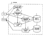
図1は、この発明の実施の形態1による現場作業支援装置の構成を示すブロック図である。
図1において、対象物を撮影するカメラ1(撮影手段)と、対象物またはその周辺に所定の情報を映像として投影するプロジェクタ2(投影手段)が配置され、カメラ1から得られた映像を基にプロジェクタで投影すべき映像を生成する計算処理部3が設けられている。
この計算処理部3の内部を構成する手段として4〜10があり、カメラとプロジェクタとの間の相対位置および姿勢を格納または計測するカメラ〜プロジェクタ間位置姿勢計測部4(投影手段撮影手段位置姿勢計測部)と、対象物の識別情報や3次元空間における位置、姿勢、形状に関するデータ(対象物のデータ)を格納する設備モデルデータベース5と、対象物とプロジェクタとの間の相対位置および姿勢を推定する対象物位置姿勢推定部6と、マーカー図形を対象物にプロジェクタで投影する映像を生成するマーカー映像生成部7と、対象物とプロジェクタとの間の相対位置および姿勢を確定算出する対象物位置姿勢確定算出部8と、対象物に関する情報や対象物に対する作業行為に関する情報を格納する作業支援情報データベース9と、作業支援情報を表現する映像(作業支援映像)を生成する作業支援映像生成部10を有している。
【0011】
次に、動作について説明する。
カメラ〜プロジェクタ位置姿勢計測部4は、カメラ1とプロジェクタ2とが支持具などで一体化されていて、相対位置および姿勢が固定されている場合は、予め計測しておいた値を格納する記憶装置によって実現され、可動機構などによって可変の場合は、適当なセンサー出力や制御機構の制御パラメータなどから両者の相対位置および姿勢を計測する装置によって実現される。
対象物位置姿勢推定部6は、カメラ1から得られた映像(対象物映像データ)を分析して、設備モデルデータベース5との照合により、映像内に写った対象物を同定するとともに、対象物とカメラ1との間の相対位置と姿勢の概略値を算出し、さらにカメラ〜プロジェクタ間位置姿勢計測部4から得られたデータに基づき、対象物とプロジェクタ2との間の相対位置と姿勢の情報に変換する。この対象物位置姿勢推定部6において算出される相対位置と姿勢は、概略値でよい。具体的な方法としては、例えば、対象物に円形のマーカーを貼り、映像内に写ったマーカーの楕円状の像の大きさ、傾き、扁平の度合を計測することによって概略値を求めることができる。
対象物の同定は、対象物ごとにマーカーの色を違えるなどして、設備モデルデータベース5との照合により行なうことができる。
【0012】
マーカー映像生成部7は、対象物位置姿勢推定部6によって推定された相対位置および姿勢と、設備モデルデータベース5に格納された対象物の形状データとから、プロジェクタ2から見て対象物が存在すると推定される領域方向に対して、所定の形と光学的特徴を有するマーカー図形が投影されるような映像を生成する。
対象物位置姿勢確定算出部8は、前記マーカー図形が対象物の表面に投影されたものをカメラ1で撮影した映像を分析してマーカー図形の像を検出し、カメラ1(またはプロジェクタ2)に対するマーカー図形の特徴点の相対位置を算出する。
さらに、そのようなマーカー図形の相対位置データと設備モデルデータベース5に格納された対象物の形状データとを照合して、カメラ1(またはプロジェクタ2)に対する対象物の相対位置および姿勢を算出する。
マーカー映像生成部7と対象物位置姿勢確定算出部8とによって実現される対象物の相対位置および姿勢の算出は、具体的には、以下のようにして行なう。(図2参照)
【0013】
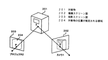
図2は、この発明の実施の形態1による現場作業支援装置の対象物の相対位置及び姿勢の算出を示す図である。
図2において、対象物201をカメラ1で撮影した映像が得られるスクリーン面(撮像スクリーン面)202と、プロジェクタ2で投影する映像が置かれるスクリーン面(投影スクリーン面)203とを有し、対象物位置姿勢推定部6で推定された対象物が、プロジェクタ2の投影スクリーン面203上で位置すると推定される領域204に表わされる。
【0014】
今、投影すべきマーカー図形は点図形とする。この時、プロジェクタ2の投影スクリーン203面におけるマーカー図形の位置P、対象物の表面に投影されたマーカー図形の位置X、カメラ1の撮像スクリーン202面におけるマーカー図形像の位置Qは、同図に示すような位置関係にある。
カメラ1とプロジェクタ2との間の相対位置および姿勢は、既に得られている。また、位置Pは、マーカー映像生成部7によって決定されるため、既知である。さらに、位置Qもカメラ1からの映像の分析結果として得られるため、既知である。したがって、対象物の表面に投影されたマーカー図形の位置Xのみが未知となるが、これは三角測量の原理に基づき、一意に求めることができる。
【0015】
対象物の表面の形状データは、設備モデルデータベース5から取得することができ、例えば平面部分に3個のマーカー図形を投影すれば、平面の位置や向きは一意に特定される。
作業支援映像生成部10は、作業支援情報データベース9を検索して対象物の諸元データ(仕様、定格、内部状態など)や対象物に対する作業指示などの作業支援情報を取得し、対象物とプロジェクタ2との間の相対位置および姿勢に基づき、これらの情報が対象物またはその周辺に重なり合うような映像を生成し、プロジェクタ2によって対象物に投影する。
【0016】
実施の形態1によれば、対象物に投影されたマーカー図形を用いて、対象物とプロジェクタとの間の相対位置および姿勢を高精度で算出するので、作業を支援する適切な情報を正しい位置に重ね合わせ表示することができる。
【0017】
実施の形態2.
実施の形態2は、対象物が所定の軌跡に沿って運動するような可動部分を有する場合に、可動部分の変位量を高精度で算出できるようにし、変位に合わせて投影すべき作業支援情報を変化させるようにしたものである。
実施の形態2の構成は、実施の形態1と同様で、図1に示されるものと同じである。
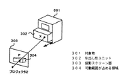
図3は、この発明の実施の形態1による現場作業支援装置のマーカー映像生成部によるマーカー図形を投影するための映像を生成する様子を示す図である。
図3において、対象物301の可動部分で、本例では直線状に前後移動する引出し形ユニット302がある。プロジェクタ2が投影する映像が置かれるスクリーン面303(投影スクリーン面)には、可動部分の形状と3次元運動軌跡データに基づいて計算された可動範囲が投影スクリーン面において占める領域304が表わされている。
【0018】
次に、動作について説明する。
対象物の固定部分とプロジェクタ2との間の相対位置および姿勢を算出する過程は、実施の形態1と同様である。
このように固定部分とプロジェクタ2との間の相対位置および姿勢が、確定算出されたのち、マーカー映像生成部7は、設備モデルデータベース5に格納された可動部分の形状データとその3次元運動軌跡データとに基づき、可動部分が運動しうる範囲を計算し、プロジェクタ2から見た可動範囲の領域方向に対して、所定の形と光学的特徴を有するマーカー図形が投影されるような映像を生成する。
【0019】
対象物位置姿勢確定部8は、マーカー図形が可動部分の表面に投影されたものをカメラ1で撮影した映像を分析してマーカー図形の像を検出し、実施の形態1に示した同様の方法により、カメラ1(またはプロジェクタ2)に対する可動部分の表面における同マーカー図形の特徴点の相対位置を計算する。さらに、設備モデルデータベース5に格納された可動部分の形状データと3次元運動軌跡データとから、可動部分の表面が上述のように算出された位置を通るような変位量を算出する。
図3において、投影すべきマーカー図形は、可動部分の運動の自由度を減じるのに十分な個数の点図形でよく、同図の例では1次元の直線運動のため1個の点図形で十分である。
作業支援映像生成部10は、このようにして算出された変位量に基づき、変位量に合わせた内容の情報を生成し、また、変位量に応じた位置に情報が表示されるような映像を生成し、プロジェクタ2によって対象物に投影する。
【0020】
なお、実施の形態2では、直線運動を行なう引出し形ユニットを可動部分として有する設備を例にして説明したが、扉や回転スイッチのような回転運動の場合や、直線運動や回転運動を組み合せた任意の運動についても同様の方法で処理することができる。
【0021】
実施の形態2によれば、対象物が所定の軌跡に沿って運動するような可動部分を持ち、作業支援情報を可動部分に対して投影する必要があるような場合でも、可動部分の変位量を高精度に算出するので、作業を支援する適切な情報を正しい位置に重ね合わせ表示することができる。
【0022】
実施の形態3.
実施の形態3は、対象物とプロジェクタとの間の相対位置や姿勢に応じて最も適した位置にマーカー図形の映像を投影するようにして、対象物とプロジェクタとの間の位置関係に関する制約を少なくしたものである。
実施の形態3の構成は、実施の形態1と同様であり、図1に示されるものと同一のものである。
図4は、この発明の実施の形態3による現場作業支援装置の対象物が直方体形状である場合に、マーカー図形を投影する様子を示す図であり、図4(a)は、正面に投影する場合、図4(b)は、正面と側面に投影する場合、図4(c)は、側面に投影する場合を示している。
【0023】
次に、動作について説明する。
マーカー映像生成部7は、対象物位置姿勢推定部6によって推定された対象物とプロジェクタ2(およびカメラ1)との間の相対位置および姿勢に基づき、対象物を構成する表面のうち、対象物位置姿勢確定算出部8における計算を最も精度よく行なえるようなマーカー図形の投影対象面を決定し、プロジェクタ1からの投影がそのような対象面に当たるよう、生成するマーカー図形の位置を計算して、投影映像を生成する。
【0024】
例えば、図4のように対象物が直方体形状である場合には、対象物とプロジェクタ2およびカメラ2との間の相対位置および姿勢の推定に基づき、
図4(a)のように、正面のみ
図4(c)のように、側面のみ
図4(b)のように、正面と側面の双方
などの組み合わせについてマーカー図形を投影した場合の計算精度を評価し、最もよい精度が期待される組み合わせを決定し、マーカー図形の映像を生成する。この場合は、平面が決められる3点以上のマーカー図形を用いる。
【0025】
実施の形態3によれば、対象物とカメラとの間の相対位置や姿勢によらず、安定して対象物の位置や姿勢を算出することができる。
【0026】
実施の形態4.
実施の形態4は、対象物をカメラで撮影して得られた画像を分析し、対象物や対象物が置かれた環境の色、明度、材質などの特徴を評価し、投影すべきマーカー図形の形や光学的特徴を決定することで、対象物位置姿勢確定算出部8におけるマーカー図形の検出をより頑健なものにしたものである。
実施の形態4の構成は、実施の形態1と同様であり、図1に示されるものと同一のものである。
【0027】
次に動作について説明する。
対象物位置姿勢推定部6は、カメラ1から得れらた映像を分析する際に、画像の色分布や明度分布など評価して、対象物表面および周囲の環境の光学的特性を表した属性情報を合わせて算出する。
マーカー映像生成部7は、対象物への相対位置および姿勢に関するデータに加えて、対象物表面および周囲の環境の光学的特性を表した属性情報も併せて対象物位置推定部6から取得し、対象物位置姿勢確定算出部8においてマーカー図形像が周辺部との間で補色効果を現すなど検出が容易となるような光学的特徴を有するマーカー図形の映像を生成する。
【0028】
実施の形態4によれば、現場ごとに環境や対象物の光学的特性が大きく変化する場合でも、安定して対象物の位置や姿勢を算出することができる。
【0029】
【発明の効果】
この発明は、以上説明したように、作業を行う対象物上または対象物の近傍に作業に関連する映像を投射して作業を支援する現場作業支援装置において、対象物に映像を投射する投射手段、この投射手段により投射された映像を撮影する撮影手段、及び投射手段により投射される映像及び撮影手段により撮影された映像を処理する計算処理部を備え、計算処理部は、投射手段と撮影手段との相対位置及び姿勢を格納または計測する投影手段撮影手段位置姿勢計測部と、対象物のデータを格納した設備モデルデータベースと、投影手段撮影手段位置姿勢計測部により格納または計測された投射手段と撮影手段との相対位置及び姿勢に基づき、対象物を撮影手段により撮影された対象物映像データと設備モデルデータベースの対象物のデータとの照合により投射手段と対象物との概略の相対位置及び姿勢を推定する対象物位置姿勢推定部と、この対象物位置姿勢推定部により推定された対象物の存在する領域に投射手段により投射されるマーカー図形を生成するマーカー映像生成部と、投射手段と撮影手段との相対位置及び姿勢に基づき、対象物に投射されたマーカー図形を撮影手段により撮影して撮影されたマーカー図形を分析することにより投射手段と対象物との相対位置及び姿勢を算出する対象物位置姿勢確定算出部と、この対象物位置姿勢確定算出部により算出された投射手段と対象物との相対位置及び姿勢に基づき投影手段により対象物に投影される対象物の作業支援映像を生成する作業支援映像生成部とによって構成されているので、投射手段と対象物との相対位置および姿勢を高精度で算出でき、作業支援映像を適確な位置に表示することができる。
【図面の簡単な説明】
【図1】この発明の実施の形態1による現場作業支援装置の構成を示すブロック図である。
【図2】この発明の実施の形態1による現場作業支援装置の対象物の相対位置及び姿勢の算出を示す図である。
【図3】この発明の実施の形態2による現場作業支援装置のマーカー映像生成部によるマーカー図形を投影するための映像を生成する様子を示す図である。
【図4】この発明の実施の形態3による現場作業支援装置の対象物が直方体形状である場合に、マーカー図形を投影する様子を示す図である。
【符号の説明】
1 カメラ、2 プロジェクタ、3 計算処理部、
4 カメラ〜プロジェクタ間位置姿勢計測部、5 設備モデルデータベース、
6 対象物位置姿勢推定部、7 マーカー映像生成部、
8 対象物位置姿勢確定算出部、9 作業支援情報データベース、
10 作業支援映像生成部、201 対象物、202 撮像スクリーン面、
203 投影スクリーン面、204 対象物の位置が推定される領域、
301 対象物、302 引出し形ユニット、303 投影スクリーン面、
304 可動範囲が占める領域。[0001]
TECHNICAL FIELD OF THE INVENTION
The present invention provides a method for performing work such as maintenance and inspection of equipment such as a plant, by superimposing information related to a work target or a work action on a video of the work target or on or around the work target itself. The present invention relates to an on-site work support device that is also displayed to support on-site work.
[0002]
[Prior art]
As a method of supporting on-site work such as maintenance and inspection of equipment such as plants, information related to the work object and work action is superimposed on the video of the work object or on the work object itself or its surroundings The display technology is known.
For example, “Image Display Apparatus and Image Display System” of Patent Document 1 discloses an example in which image information is projected on or around an object as an application of such technology. Here, based on an image obtained from a camera or information obtained from a position and orientation measurement device (realized by a magnetic sensor, a gyro, an ultrasonic sensor, etc.), a relative position and an orientation with respect to an object are determined. The projection information search unit searches the projection information database based on the measurement and calculation, and the image information generation unit generates an image to be projected. By doing so, the information of the work support is superimposed and displayed on the object itself or its surroundings, so that there is an advantage that the information can be shared by a plurality of workers.
[0003]
Patent Document 2 discloses an example in which a “work information presentation device” further includes a means for identifying a work action, compares the work action with a content assumed in advance, and presents information corresponding to the work action to a worker. ing. The information superimposing device of Patent Document 2 includes a method of superimposing and displaying video information as shown in the example of Patent Document 1 around an object or its surroundings. By identifying the work action and comparing it with the work action content assumed in advance by the work action comparison means, there is an advantage that an error preventing effect is brought about.
[0004]
Here, the conventional method for grasping the relative position between the projecting means and the work target as shown in Patent Document 1 is roughly divided into the following two types.
A: The absolute position of the device (camera + projector) is measured using a sensor (magnetism, ultrasonic wave, gyro, etc.), and the relative position with respect to an object (a position can be obtained from a database or the like) is calculated. (Patent Document 1)
B: Obtain an image of the target object from the camera, analyze the image, and calculate the relative position between the camera (and the device) and the target object. The following methods B1 and B2 are typical.
B1: A disk-shaped marker is attached to the object, and an image of the marker is analyzed. The relative position with respect to the camera is calculated from the size of the marker image and the degree of deformation on the image.
B2: Analyze an image in which feature points (vertexes and the like) of the object are captured. For a plurality of feature points, a relative position with respect to the camera is calculated from the positions of the images of the feature points on the image.
[0005]
[Patent Document 1]
Japanese Patent No. 3274290 (paragraph numbers 0040 to 0045, FIG. 1)
[Patent Document 2]
JP 2001-282349 A (paragraph numbers 0019 to 0034, FIG. 1)
[0006]
[Problems to be solved by the invention]
In order to superimpose and display information on and around the work object, the relative position and orientation between the work object and the projection display means must be determined with high accuracy.
Further, when the work object has a movable part and the movable part is largely displaced as a result of a work action or as a result of a change in the internal state of the object, the content and display position of the information to be superimposed and displayed. Needs to be changed according to the displacement. Therefore, it is necessary that the displacement amount of the movable part be determined with high accuracy.
In addition, the support device is required to have portability, to be small, light, and simple so as not to hinder on-site work.
[0007]
The above-mentioned method A has a problem that the whole apparatus including the sensor system becomes large and complicated, and a problem that portability such as using the apparatus while moving it at a plurality of sites is difficult to realize.
In the method of B1, it is difficult to accurately measure the size and degree of deformation of the marker image on the image, and the accuracy of the calculated relative position is low. Problem.
Further, in the method of B2, it is necessary that all the feature points required for calculation are included in the image. That is, it is necessary to install the device at a position where such an image can be taken, and there is a problem that the installation place is limited, and when an image from a camera is subjected to image processing to detect an image of a feature point, There has been a problem that detection may not be possible depending on lighting conditions.
[0008]
SUMMARY OF THE INVENTION The present invention has been made to solve the above-described problem, and has as its object to obtain a field work support apparatus that accurately calculates a relative position and orientation between a projection unit and a work object. ing.
[0009]
[Means for Solving the Problems]
In a field work support apparatus according to the present invention, a field work support apparatus for projecting an image related to a work on or near an object on which the work is performed to support the work, and projecting an image on the object Means, a photographing means for photographing an image projected by the projecting means, and a calculation processing section for processing the image projected by the projection means and the image photographed by the photographing means. Projection means photographing means position / posture measuring unit for storing or measuring relative position and posture with respect to the means, equipment model database storing object data, and projecting means stored or measured by projecting means photographing means position / posture measuring unit Based on the relative position and orientation of the object and the photographing means, the object image data of the object photographed by the photographing means and the object in the equipment model database An object position / posture estimating unit for estimating the approximate relative position and orientation of the projecting means and the object by collation with data; and a projecting means for projecting the area where the object estimated by the object position / posture estimating unit exists A marker image generation unit that generates a marker figure to be projected, and analyzes the marker figure photographed by photographing the marker figure projected on the target object by the photographing unit based on the relative position and orientation of the projecting unit and the photographing unit. An object position and orientation determination calculation unit that calculates the relative position and orientation of the projection unit and the object by performing the calculation, and the relative position and orientation of the projection unit and the object calculated by the object position and orientation determination calculation unit And a work support video generation unit that generates a work support video of the target projected on the target by the projection unit.
[0010]
BEST MODE FOR CARRYING OUT THE INVENTION
Embodiment 1 FIG.
FIG. 1 is a block diagram showing a configuration of a field work support apparatus according to Embodiment 1 of the present invention.
In FIG. 1, a camera 1 (imaging means) for photographing an object and a projector 2 (projecting means) for projecting predetermined information as an image on or around the object are arranged, and based on an image obtained from the camera 1. Is provided with a calculation processing unit 3 for generating an image to be projected by the projector.
There are 4 to 10 as means constituting the inside of the calculation processing unit 3, and a camera-to-projector position / posture measuring unit 4 (projection unit photographing unit position / posture) for storing or measuring the relative position and posture between the camera and the projector. Measurement equipment), an equipment model database 5 for storing identification information of the object and data on the position, orientation, and shape in the three-dimensional space (object data), and the relative position and orientation between the object and the projector. A target position / posture estimating unit 6 for estimating, a marker image generating unit 7 for generating an image of projecting the marker graphic onto the target object by the projector, and an object for determining and calculating the relative position and orientation between the target object and the projector A position and orientation determination calculation unit 8 and a work support information database 9 for storing information about the object and information about a work action on the object Has a work support video generation unit 10 for generating a video (work support video) representing the work support information.
[0011]
Next, the operation will be described.
The camera-projector position / posture measuring unit 4 stores a value measured in advance when the camera 1 and the projector 2 are integrated by a support or the like and the relative position and posture are fixed. When realized by a device and can be changed by a movable mechanism or the like, it is realized by a device that measures the relative position and orientation of the two from an appropriate sensor output or a control parameter of a control mechanism.
The target position / posture estimating unit 6 analyzes the video (target video data) obtained from the camera 1, identifies the target in the video by collating with the equipment model database 5, and Approximate values of the relative position and orientation between the camera and the camera 1 are calculated, and based on data obtained from the position and orientation measurement unit 4 between the camera and the projector, the relative position and orientation of the object and the projector 2 are calculated. Convert to information. The relative position and orientation calculated by the target object orientation estimation unit 6 may be approximate values. As a specific method, for example, an approximate value can be obtained by pasting a circular marker on an object and measuring the size, inclination, and degree of flatness of the elliptical image of the marker in the video. .
The identification of the target object can be performed by comparing the marker color for each target object with the equipment model database 5.
[0012]
Based on the relative position and orientation estimated by the object position / posture estimating unit 6 and the shape data of the object stored in the facility model database 5, the marker image generation unit 7 determines that the object is present as viewed from the projector 2. An image is generated such that a marker figure having a predetermined shape and optical characteristics is projected in the estimated area direction.
The target object position / posture determination calculation unit 8 detects an image of the marker graphic by analyzing an image of the marker graphic projected on the surface of the target taken by the camera 1, and detects the image of the marker graphic for the camera 1 (or the projector 2). Calculate the relative positions of the feature points of the marker figure.
Further, the relative position and orientation of the target object with respect to the camera 1 (or the projector 2) are calculated by comparing the relative position data of such a marker figure with the shape data of the target object stored in the equipment model database 5.
The calculation of the relative position and orientation of the object realized by the marker image generation unit 7 and the object position and orientation determination calculation unit 8 is specifically performed as follows. (See Fig. 2)
[0013]
FIG. 2 is a diagram showing calculation of the relative position and posture of the target object by the on-site work support device according to the first embodiment of the present invention.
In FIG. 2, the target 201 has a screen surface (imaging screen surface) 202 on which an image captured by the camera 1 is obtained, and a screen surface (projection screen surface) 203 on which an image projected by the projector 2 is placed. The target object estimated by the object position / posture estimating unit 6 is represented by an area 204 estimated to be located on the projection screen surface 203 of the projector 2.
[0014]
Now, the marker figure to be projected is a point figure. At this time, the position P of the marker figure on the projection screen 203 of the projector 2, the position X of the marker figure projected on the surface of the object, and the position Q of the marker figure image on the imaging screen 202 of the camera 1 are shown in FIG. The positional relationship is as shown.
The relative position and orientation between the camera 1 and the projector 2 have already been obtained. Further, the position P is known because it is determined by the marker video generation unit 7. Further, the position Q is also known because it is obtained as a result of analyzing the image from the camera 1. Therefore, only the position X of the marker figure projected on the surface of the object is unknown, but can be uniquely obtained based on the principle of triangulation.
[0015]
The shape data of the surface of the object can be acquired from the equipment model database 5. For example, when three marker figures are projected on a plane portion, the position and orientation of the plane are uniquely specified.
The work support video generation unit 10 searches the work support information database 9 to acquire work support information such as specification data (specifications, ratings, internal states, etc.) of the object and work instructions for the object, and Based on the relative position and orientation with respect to the projector 2, an image in which such information overlaps the object or its surroundings is generated, and the projector 2 projects the image on the object.
[0016]
According to the first embodiment, the relative position and orientation between the object and the projector are calculated with high accuracy by using the marker figure projected on the object, so that appropriate information for supporting the work is set to the correct position. Can be superimposed and displayed.
[0017]
Embodiment 2 FIG.
In the second embodiment, when the object has a movable part that moves along a predetermined trajectory, the displacement amount of the movable part can be calculated with high accuracy, and work support information to be projected according to the displacement Is changed.
The configuration of the second embodiment is the same as that of the first embodiment, and is the same as that shown in FIG.
FIG. 3 is a diagram showing how a marker image generating unit of the on-site work supporting apparatus according to the first embodiment of the present invention generates an image for projecting a marker figure.
In FIG. 3, there is a drawer-type unit 302 which is a movable part of an object 301 and moves linearly back and forth in this example. On the screen surface 303 (projection screen surface) on which the image projected by the projector 2 is placed, an area 304 occupied by the movable range calculated based on the shape of the movable part and the three-dimensional motion trajectory data is shown. ing.
[0018]
Next, the operation will be described.
The process of calculating the relative position and orientation between the fixed part of the object and the projector 2 is the same as in the first embodiment.
After the relative position and orientation between the fixed part and the projector 2 have been determined and calculated in this way, the marker image generation unit 7 determines the shape data of the movable part stored in the equipment model database 5 and its three-dimensional motion trajectory. Based on the data, a range in which the movable part can move is calculated, and an image is generated in which a marker figure having a predetermined shape and optical characteristics is projected in the direction of the movable range viewed from the projector 2. I do.
[0019]
The object position / posture determination unit 8 analyzes the image of the marker graphic projected on the surface of the movable part by using the camera 1 to detect the image of the marker graphic, and detects the image of the marker graphic in the same manner as described in the first embodiment. , The relative position of the characteristic point of the marker figure on the surface of the movable part with respect to the camera 1 (or the projector 2) is calculated. Further, from the shape data of the movable part and the three-dimensional motion trajectory data stored in the equipment model database 5, a displacement amount such that the surface of the movable part passes through the position calculated as described above is calculated.
In FIG. 3, the marker figure to be projected may be a sufficient number of point figures to reduce the degree of freedom of movement of the movable part, and in the example of FIG. 3, one point figure is sufficient for one-dimensional linear movement. It is.
The work support image generation unit 10 generates information having contents corresponding to the displacement amount based on the displacement amount calculated in this manner, and generates an image in which information is displayed at a position corresponding to the displacement amount. It is generated and projected on the target object by the projector 2.
[0020]
In the second embodiment, the equipment having a drawer unit that performs a linear motion as a movable part has been described as an example. However, in the case of a rotary motion such as a door or a rotary switch, or a combination of a linear motion and a rotary motion. Any exercise can be handled in a similar manner.
[0021]
According to the second embodiment, even when the object has a movable part that moves along a predetermined trajectory and it is necessary to project work support information onto the movable part, the displacement amount of the movable part Is calculated with high accuracy, so that appropriate information for supporting the work can be superimposed and displayed at the correct position.
[0022]
Embodiment 3 FIG.
In the third embodiment, the restriction on the positional relationship between the target object and the projector is set by projecting the image of the marker figure at the most suitable position according to the relative position and orientation between the target object and the projector. It is less.
The configuration of the third embodiment is the same as that of the first embodiment, and is the same as that shown in FIG.
FIG. 4 is a diagram showing a manner in which a marker figure is projected when the target of the on-site work assisting apparatus according to the third embodiment of the present invention has a rectangular parallelepiped shape. FIG. In this case, FIG. 4B shows a case where the image is projected on the front and side surfaces, and FIG. 4C shows a case where the image is projected on the side surface.
[0023]
Next, the operation will be described.
The marker image generation unit 7 is configured to output the target image among the surfaces constituting the target object based on the relative position and the posture between the target object and the projector 2 (and the camera 1) estimated by the target object position / posture estimation unit 6. The position of the marker figure to be projected is determined so that the calculation by the position / posture determination calculation unit 8 can be performed with the highest accuracy, and the position of the marker figure to be generated is calculated so that the projection from the projector 1 hits such a target plane. And generate a projection image.
[0024]
For example, when the target has a rectangular parallelepiped shape as shown in FIG. 4, based on the estimation of the relative position and orientation between the target and the projector 2 and the camera 2,
As shown in FIG. 4 (a), the calculation accuracy when projecting a marker figure for a combination of both the front and the side as shown in FIG. 4 (b) and only the side as shown in FIG. It evaluates, determines the combination that is expected to have the best accuracy, and generates an image of the marker figure. In this case, three or more marker figures that determine the plane are used.
[0025]
According to the third embodiment, it is possible to stably calculate the position and the posture of the target object irrespective of the relative position and the posture between the target object and the camera.
[0026]
Embodiment 4 FIG.
In the fourth embodiment, an image obtained by photographing an object with a camera is analyzed, characteristics such as color, brightness, and material of the object and the environment where the object is placed are evaluated. By determining the shape and optical characteristics of the object, the detection of the marker figure in the object position / posture determination calculation unit 8 is made more robust.
The configuration of the fourth embodiment is the same as that of the first embodiment, and is the same as that shown in FIG.
[0027]
Next, the operation will be described.
When analyzing the video obtained from the camera 1, the target position / posture estimating unit 6 evaluates the color distribution and the lightness distribution of the image, and expresses the attributes representing the optical characteristics of the surface of the target and the surrounding environment. Calculate based on the information.
The marker image generation unit 7 acquires from the object position estimating unit 6 the attribute information representing the optical characteristics of the surface of the object and the surrounding environment, in addition to the data on the relative position and orientation with respect to the object, The object position / posture determination calculation unit 8 generates a marker graphic image having optical characteristics that facilitate detection, such as a complementary color effect between the marker graphic image and the peripheral part.
[0028]
According to the fourth embodiment, even when the environment and the optical characteristics of the target change greatly at each site, the position and orientation of the target can be calculated stably.
[0029]
【The invention's effect】
As described above, according to the present invention, a projecting means for projecting an image on a target object in a field work support apparatus for projecting an image related to the work on or near the target object to assist the work. Photographing means for photographing the image projected by the projecting means, and a calculation processing unit for processing the image projected by the projection means and the image photographed by the photographing means. Projection means photographing means position or orientation measuring unit for storing or measuring relative position and orientation with, equipment model database storing object data, and projecting means stored or measured by projecting means imaging means position and orientation measuring unit. Based on the relative position and orientation with respect to the photographing means, the object image data of the object photographed by the photographing means and the data of the object in the equipment model database. An object position / posture estimating unit for estimating the approximate relative position and orientation of the projecting means and the object in some cases; A marker image generating unit for generating a marker figure, and analyzing the marker figure photographed by photographing the marker figure projected on the object by the photographing means based on the relative position and orientation of the projecting means and the photographing means. An object position / posture determination calculation unit that calculates a relative position and orientation between the projection unit and the object; and a projection unit based on the relative position and orientation between the projection unit and the object calculated by the object position / posture determination calculation unit And a work support image generation unit that generates a work support image of the object projected on the object, so that the relative position of the projection means and the object and The energizing can be calculated with high accuracy, it is possible to display the work support video to accurately position.
[Brief description of the drawings]
FIG. 1 is a block diagram showing a configuration of a field work support device according to a first embodiment of the present invention.
FIG. 2 is a diagram illustrating calculation of a relative position and a posture of an object by the on-site work support device according to the first embodiment of the present invention;
FIG. 3 is a diagram showing a manner in which an image for projecting a marker graphic is generated by a marker image generation unit of a site work support apparatus according to a second embodiment of the present invention;
FIG. 4 is a diagram showing a manner in which a marker figure is projected when an object of the on-site work support device according to a third embodiment of the present invention has a rectangular parallelepiped shape;
[Explanation of symbols]
1 camera, 2 projectors, 3 calculation processing unit,
4 Camera and projector position and orientation measurement unit, 5 Equipment model database,
6 object position and orientation estimator, 7 marker video generator,
8 object position and orientation determination calculation unit, 9 work support information database,
10 work support video generation unit, 201 object, 202 imaging screen surface,
203 projection screen plane, 204 area where the position of the object is estimated,
301 object, 302 drawer unit, 303 projection screen surface,
304 Area occupied by the movable range.