JP2004346643A - Monitoring device for construction machine - Google Patents
Monitoring device for construction machine Download PDFInfo
- Publication number
- JP2004346643A JP2004346643A JP2003145885A JP2003145885A JP2004346643A JP 2004346643 A JP2004346643 A JP 2004346643A JP 2003145885 A JP2003145885 A JP 2003145885A JP 2003145885 A JP2003145885 A JP 2003145885A JP 2004346643 A JP2004346643 A JP 2004346643A
- Authority
- JP
- Japan
- Prior art keywords
- construction machine
- switch
- screen
- camera
- monitoring device
- Prior art date
- Legal status (The legal status is an assumption and is not a legal conclusion. Google has not performed a legal analysis and makes no representation as to the accuracy of the status listed.)
- Granted
Links
Images


Abstract
Description
【0001】
【発明の属する技術分野】
この発明は、建設機械のモニタ装置に関するものである。更に具体的にはモニタ装置に表示する画像を切替える切替え装置に関するものである。
【0002】
【従来技術】
油圧ショベル等の建設機械は下部走行体の上に上部旋回体が旋回自在に載置され、上部旋回体の上にオペレータキャブが設けられている。オペレータキャブは上部旋回体の前方に設けられると共に前方の視野を確保するために前面窓は広く設けられている。オペレータキャブの後方にも窓が設けられているが、しかしオペレータキャブの後方には種々の装置が配置するために収納ハウスカバーやカウンタウエイトが設けられている。従って、建設機械の後方やオペレータキャブの反対側側面は視界が遮られ、障害物の確認に困難が伴う。このために、下部走行体が後退する際、或いは、上部旋回体が旋回(特に反対方向に旋回)する際に障害物確認のために建設機械にカメラを装着して、このカメラの画像をモニタに表示して障害物を確認する方法が採用されている。
【0003】
一方、建設機械には作業機が設置されており、作業機に関する運転状況をオペレータに知らせるために種々のデータ等を表示するモニタがフロント(例えば、フロントパネル)に装着されている。複数のモニタをフロントに装着すると煩雑になり、オペレータにとっても見難いものとなる。そこで、1個のモニタに、作業機データの表示と後方画像の表示を切替えて両者を表示可能な方式が採用されている。この切替え表示方式に関して従来から種々の考案がなされている。
【0004】
従来装置のカメラの取付け位置と切替え表示方式の例として、公開特許公報、特開2001−295321号に記載された例を図6及び図7に示す。図6は建設機械50の平面図で、下部走行体51の上に上部旋回体52が旋回自在に載置されている。上部旋回体52の左側先頭にキャブハウス53が設置され、作業機54が前方中央に装着されている。また、第1カメラ55と第2カメラ56が後方端の両側に設けられている。図の斜線部はカメラの視野を示す。又図中の矢印は上部旋回体52の旋回方向を示す。
【0005】
図7はこの切替え装置を油圧ショベルに適用した回路で、カメラ55,56の映像はコントローラ66に入力されている。一方、旋回操作の信号も圧力スイッチ64,65からコントローラ66に入力されている。旋回操作信号は油圧ポンプ58の下流に接続された切替え弁59のパイロットポートに旋回モータ60のリモコン弁62からの出力SR,SLが印加されるように接続されており、これらの出力が同時に圧力スイッチ64,65にも印加されている。なお、リモコン弁62にはパイロット油圧ポンプ61、油タンク57が接続されている。選択スイッチ67は手動切替えモードと自動切替えモードを選択するスイッチである。
【0006】
コントローラ66は、運転者が自動切替えモードを選択すると、以下のように機能するように構成されている。例えば、運転者が操作レバー62aを右旋回側(左旋回側)に倒すとリモコン弁62から出力SR(SL)が出力され、圧力スイッチ64(65)がオンになり、コントローラ66はカメラ55(56)の画像をモニタ63に表示する。又、手動切替えモードを選択した場合は運転者が指定した方のカメラ55(56)の画像をモニタ63に表示される。
【0007】
【発明が解決しようとする課題】
以上に説明したように、従来装置では複数の固定カメラを使用してモニタ表示の切替えを行っている。上記で説明したもの以外にも、例えば、公開特許公報、特開2002−201676号では3個のカメラを装着している。このように複数のカメラを使用すると画像と実際の位置関係について頭の中で混乱しがちになるという課題が生じる。又、切替えが複雑になるという課題も生じる。上記の公報には何れも取付け個所は記載されていないが、切替えのためのスイッチを設ける個所の選択も複雑になるという課題も生じる。
【0008】
本発明は、上記事実に鑑みなされたものであり、カメラを1個にして切替えを簡単化すると共に切替えスイッチを操作のし易い位置に設けて機械や装置のデータ表示と後方画像表示の切替え操作を容易にしたモニタ表示装置を提供することを課題とする。
【0009】
【課題を解決するための手段】
本発明は上記の課題を解決するための手段として以下の構成を採用している。即ち、
請求項1に記載の発明は、建設機械のキャブ前面にモニタを装備した建設機械のモニタ装置において、該モニタ装置に機械の操作状態を表示する画面と後方の操作環境を示す画像を表示する画面とを切替える画面切替えスイッチをオペレータの操作レバーに設けたことを特徴としている。
また、請求項2に記載の発明は、請求項1に記載の発明において、前記画面切替えスイッチは該スイッチを押す毎に状態が遷移するモーメンタリースイッチで構成したことを特徴としている。
【0010】
請求項3に記載の発明は、請求項1〜請求項2に記載の発明において、前記モニタ装置は、機械の操作状態を表示するモードと後方の画像を表示するモードとを選択するモード選択スイッチを更に設けたことを特徴とする。
また、請求項4に記載の発明は、請求項1〜請求項3に記載の発明において、前記モード選択スイッチは、後方画像表示モードを選択した場合には常時後方画像を表示し、所定の操作状態表示要求があった場合に一定時間その要求に対応した画面を表示し、一定時間経過後は再度後方画像を表示するように構成したことを特徴としている。 また、請求項5に記載の発明は、請求項1〜請求項4に記載の発明において、前記所定の操作状態表示要求は、例えば、ラジエータの水温が高くなった場合や燃料残量が少なくなった場合等の機械操作状態に異変が生じた場合、或いはラジエータの水温がオーバーヒート状態になった場合や燃料残量がエンプティ状態等の警報表示を必要とする場合等において要求信号を出力するように構成したことを特徴とする。
【0011】
請求項6に記載の発明は、請求項1〜請求項5に記載の発明において、前記モード選択スイッチは、操作状態表示モードを選択した場合には前記画面切替えスイッチをスイッチオンする毎に操作状態表示画面と後方画像表示画面とが交互に切替わるように構成したことを特徴としている。
【0012】
請求項7に記載の発明は、請求項1〜請求項6に記載の発明において、前記後方画像を撮影するカメラは、CCDカメラで構成したことを特徴とする。
また、請求項8に記載の発明は、請求項1〜請求項7に記載の発明において、前記後方画像を撮影するカメラは、広角度レンズを使用したカメラで構成したことを特徴とする。
【0013】
請求項9に記載の発明は、請求項1〜請求項8に記載の発明において、前記後方画像を撮影するカメラは、建設機械に搭載するカウンタウエイトの上側表面に保護ボックスを装着してその保護ボックスに設けたこと、或いは、カウンタウエイトの後方上部に切り欠き部を設け、該切り欠き部に設置したことを特徴としている。
【0014】
請求項10に記載の発明は、請求項1〜請求項9に記載の発明において、前記カメラは左右又は上下に揺動可能に設けたことを特徴とする。
【0015】
請求項11に記載の発明は、請求項1〜請求項10に記載の発明において、前記画像表示切替えスイッチをホーンスイッチと兼用したことを特徴とする。
【0016】
【発明の実施の形態】
以下本発明の実施形態を図に基づいて説明する。
図1は、本発明を実施した実施形態の構成概要を示す図であり、図2は切替えスイッチとモニタの表示内容との関係を説明した図である。図3は上記の実施形態の一部を変更した例を示す図である。図4は本発明を実施した建設機械を示す図で、図5はオペレータの運転席を示す図である。
【0017】
図4は油圧ショベル10の左側面図を示す。図4において、油圧ショベル10の下部には下部走行体11が設けられており、その上に旋回フレーム12が旋回自在に載置されている。旋回フレーム13の左側前方にはキャブ13が設けられており、その後方中央部には種々の装置、機械を収納するハウス14が設けられており、後尾にはカウンタウエイト15が設けられている。また、前方中央にはブーム、アーム等からなる作業機16が設けられている。カウンタウエイト15の上側面には後方画像を撮影するビデオカメラ20が設置されている。
【0018】
図5は左側壁を取り除いたキャブ内の斜視図を示す。図5において、略中央部にはオペレータの運転席18が設けられており、運転席18の左右両側にコンソールボックス19a、19bが設けられている。コンソールボックス19a、19bの上側表面には操作レバー21a、21bが設けられている。また、運転席18の前方には一対の走行レバー22が設けられている。更に、図示されていないフロントパネルにはモニタ23が装着されている。モニタ23は機械や装置の状態を表示するため、及び後方画像を表示するために使用される。
【0019】
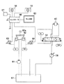
本実施形態は、図1に示すように、操作レバー21(21a又は21b)に設けられた画面切替えスイッチ25及びコンソール19(19a又は19b)に設けられたモード選択スイッチ26と、機械や装置等の種々の状態(燃料残量、冷却水温度、その他)を検出する一群のセンサ27と、カウンタウエイト15の上部に設けられた上部旋回体12の後方の状況を撮影するビデオカメラ20と、画面を表示するモニタ23及びモニタに表示する画面を制御しているコントローラ28とを具備している。なお、コントローラ28は入力用バッファ29a、出力用バッファ29b、コンピュータ30、時計31、入力端末32等を具備しており、スイッチ25,26、及び一群のセンサ27、カメラ20の画像出力端がコントローラ28の入力側に接続され、モニタ23が出力側に接続されている。
【0020】
スイッチ25はモーメンタリースイッチで押し釦を押す毎に2つの状態が交互に遷移するように構成されたスイッチである。即ち、押し釦25を1回押すと、状態表示画面から後方画像表示画面に切替わり、或いは逆に、後方画像表示画面から状態表示画面に切替わる。スイッチ26は、選択スイッチで、一方の側に倒すと機械画像表示モードになり、他方の側に倒すと後方画像表示モードになるように構成されている。選択スイッチ26は、モーメンタリースイッチ25と同じ側のコンソールボックスに設けてもよいし、或いは反対側のコンソールボックスに設けてもよい。カメラ20は、例えばCCD(電荷結合素子)を利用したカメラでデジタル画像を出力するのが好ましい。更にカメラ20のレンズは広角レンズであることが望ましい。カメラ20はカウンタウエイト15の上側表面に図示省略の保護ケースを設けて、その保護ケースに設置してもよい。或いは、図3に示すように、カウンタウエイト15の外側面に切欠き部を設けて、そこに設置してもよい。
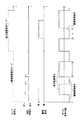
【0021】
図2はコントローラ28の機能を説明したタイミングチャートである。図2において、モード選択スイッチ26を機械画像表示モードにした状態で、画面切替えスイッチ25の押し釦を押すと、モニタ23の表示が機械画像表示から後方画像表示に切り換って、カメラ20で撮影されている画像が表示される。なお、後方画像表示をしているときに表示時間が所定の時間(t1)を超えると自動的に機械画像表示に戻るようにプログラムされている。次に、再度押し釦25を押すとモニタ23の表示が後方画像表示から機械画像表示に切り換り、水温、燃料残量、その他の機械や装置に関するデータがモニタ23に表示される。なお、図2では図示を省略しているが、機械画像表示中に警報表示要求があった場合は警報画像が表示される。
【0022】
モード選択スイッチ26を後方画像表示モードにした状態では常時後方画像がモニタ23に表示される。しかし、警報表示要求があった場合は一定時間(t2)だけ警報画像が表示され、その後は再び後方画像が表示される。
【0023】
図3は上記の実施形態を一部変更した実施例を示す。図3(A)はカメラ20を設置する場所として、カウンタウエイト15の外側上部に切欠き部41を設け、切欠き部41の内部に装着した場合を示す。切欠き部41の外側に開閉扉42を設けてカメラ20内に埃、ごみ等の進入防止とレンズの汚れ防止を図ってもよい。図3(B)は従来技術のリンクを使用した揺動機構を利用してカメラ20に左右又は上下に揺動可能に設けた場合の操作釦を示す。例えば、中央にモーメンタリースイッチ25を設けて、その周囲に揺動スイッチ釦43a〜43dを設けた例を示す。モーメンタリースイッチ25を押して後方画像表示にしたときに、カメラ20のレンズは中央方向に向くようにする。そして、揺動スイッチ釦43a(43b〜43dも同様)を押している間カメラ20のレンズは同じ方向(例えば、左側)に緩やかに向きが変化するようにしてもよいし、或いは揺動スイッチ釦43aを1回押す度に所定の小角度だけ緩やかに向きが変化するようにしてもよい。
【0024】
以上に説明した実施形態では、画面切替えスイッチ25はモーメンタリースイッチで構成し、操作レバーに設けたので、オペレータは操作レバーで操作しながら、画面切替えスイッチ25を操作することができる。従って、オペレータの作業操作が容易になるという効果が得られる。又、画面切替えスイッチ25の他に選択スイッチ26を設けて種々の場合に対応できるようにしたので、複雑な作業に対応できるという効果が得られる。一方、撮像カメラは1個のみを採用しているために、スイッチ操作は簡単な構成となっている。
【0025】
以上本発明の実施形態を図面に基づいて詳述してきたが、本発明の技術的範囲はこれに限られるものではなく、例えば、画面切替えスイッチ25とホーンスイッチとを兼用するようにしてもよい。
【0026】
【発明の効果】
画面切替えスイッチは操作レバーに設けたので、オペレータは操作レバーで操作しながら、画面切替えスイッチを操作することができる。従って、オペレータの作業操作が容易になるという効果が得られる。又、画面切替えスイッチの他に選択スイッチを設けて種々の場合に対応できるようにしたので、複雑な作業に対応できるという効果が得られる。
【図面の簡単な説明】
【図1】本発明を実施した実施形態の構成概要を示す。
【図2】切替えスイッチとモニタの表示内容とのタイミングチャートを示す。
【図3】上記の実施形態の一部を変更した実施例を示す。
【図4】本発明を実施した建設機械を示す。
【図5】キャブ内のオペレータの運転席を示す。
【図6】従来装置を利用した油圧ショベルの平面図を示す。
【図7】従来装置を利用した回路図を示す。
【符号の説明】
15 カウンタウエイト
19 コンソールボックス
20 カメラ
21 操作レバー
23 モニタ
25 画面切替えスイッチ
26 モード選択スイッチ
27 センサ端末
28 コントローラ[0001]
TECHNICAL FIELD OF THE INVENTION
The present invention relates to a monitoring device for a construction machine. More specifically, the present invention relates to a switching device for switching an image displayed on a monitor device.
[0002]
[Prior art]
In a construction machine such as a hydraulic excavator, an upper revolving unit is rotatably mounted on a lower traveling unit, and an operator cab is provided on the upper revolving unit. The operator cab is provided in front of the upper revolving superstructure, and a front window is widely provided to secure a front view. Windows are also provided behind the operator cab, but storage housing covers and counterweights are provided behind the operator cab for placement of various devices. Therefore, the view behind the construction machine and the side opposite to the operator cab is obstructed, making it difficult to check for obstacles. For this reason, a camera is attached to the construction machine to check for obstacles when the lower traveling structure moves backward or when the upper revolving structure turns (particularly turning in the opposite direction), and the image of the camera is monitored. Is displayed to check for obstacles.
[0003]
On the other hand, a working machine is installed in the construction machine, and a monitor that displays various data and the like is mounted on a front (for example, a front panel) to inform an operator of an operation state of the working machine. If a plurality of monitors are mounted on the front, it becomes complicated and difficult for an operator to see. Therefore, a method is adopted in which one monitor can switch between display of work implement data and display of a rear image to display both. Various ideas have been devised for this switching display method.
[0004]
FIGS. 6 and 7 show examples of a mounting position of a camera and a switching display method of a conventional device, which are described in JP-A-2001-295321. FIG. 6 is a plan view of the
[0005]
FIG. 7 shows a circuit in which this switching device is applied to a hydraulic excavator, and the images of the
[0006]
The
[0007]
[Problems to be solved by the invention]
As described above, the conventional apparatus switches the monitor display using a plurality of fixed cameras. In addition to those described above, for example, in Japanese Patent Laid-Open Publication No. 2002-201676, three cameras are mounted. As described above, when a plurality of cameras are used, there is a problem in that the relationship between the image and the actual positional relationship tends to be confused in the mind. Further, there is a problem that switching is complicated. Although the above publications do not disclose any mounting locations, there is also a problem that the selection of the locations where switches for switching are provided becomes complicated.
[0008]
SUMMARY OF THE INVENTION The present invention has been made in view of the above-described circumstances, and simplifies switching with a single camera, and provides a changeover switch at an easily operable position to switch between data display and rear image display of machines and devices. It is an object to provide a monitor display device which facilitates the above.
[0009]
[Means for Solving the Problems]
The present invention employs the following configuration as means for solving the above-mentioned problems. That is,
According to the first aspect of the present invention, there is provided a monitor for a construction machine equipped with a monitor on a front surface of a cab of the construction machine, wherein the monitor displays a screen showing an operation state of the machine and an image showing an operation environment behind the monitor. And a screen changeover switch for switching between the operation lever and the operation lever is provided on the operation lever of the operator.
According to a second aspect of the present invention, in the first aspect of the present invention, the screen changeover switch is constituted by a momentary switch whose state changes each time the switch is pressed.
[0010]
According to a third aspect of the present invention, in the first or second aspect of the invention, the monitor device is a mode selection switch for selecting a mode for displaying a machine operation state and a mode for displaying a rear image. Is further provided.
According to a fourth aspect of the present invention, in the first to third aspects of the present invention, the mode selection switch always displays a rear image when the rear image display mode is selected, and performs a predetermined operation. When a status display request is made, a screen corresponding to the request is displayed for a certain period of time, and after a certain period of time, the rear image is displayed again. According to a fifth aspect of the present invention, in the first to fourth aspects of the invention, the predetermined operation state display request is, for example, when the water temperature of the radiator becomes high or the remaining fuel amount becomes small. Output a request signal when an abnormal condition occurs in the machine operation state, such as when the water temperature of the radiator becomes overheated, or when the remaining fuel needs an alarm display such as an empty state. It is characterized by comprising.
[0011]
According to a sixth aspect of the present invention, in the first aspect of the present invention, when the operation state display mode is selected, the mode selection switch operates each time the screen changeover switch is turned on. The display screen and the rear image display screen are alternately switched.
[0012]
According to a seventh aspect of the present invention, in the first to sixth aspects of the present invention, the camera that captures the rear image is a CCD camera.
According to an eighth aspect of the present invention, in the first to seventh aspects of the present invention, the camera that captures the rear image is a camera using a wide-angle lens.
[0013]
According to a ninth aspect of the present invention, in the first to eighth aspects of the present invention, the camera for photographing the rear image is provided with a protective box mounted on an upper surface of a counterweight mounted on a construction machine to protect the counterweight. It is characterized in that it is provided in a box, or that a notch is provided in the upper rear part of the counterweight, and the notch is installed in the notch.
[0014]
According to a tenth aspect of the present invention, in the first to ninth aspects of the present invention, the camera is provided so as to be able to swing left and right or up and down.
[0015]
According to an eleventh aspect of the present invention, in the first to tenth aspects, the image display changeover switch is also used as a horn switch.
[0016]
BEST MODE FOR CARRYING OUT THE INVENTION
Hereinafter, embodiments of the present invention will be described with reference to the drawings.
FIG. 1 is a diagram showing a schematic configuration of an embodiment of the present invention, and FIG. 2 is a diagram for explaining a relationship between a changeover switch and display contents of a monitor. FIG. 3 is a diagram showing an example in which a part of the above embodiment is modified. FIG. 4 is a diagram illustrating a construction machine embodying the present invention, and FIG. 5 is a diagram illustrating a driver's seat of an operator.
[0017]
FIG. 4 is a left side view of the
[0018]
FIG. 5 shows a perspective view of the inside of the cab with the left side wall removed. In FIG. 5, a driver's
[0019]
In the present embodiment, as shown in FIG. 1, a
[0020]
The
[0021]
FIG. 2 is a timing chart illustrating the function of the
[0022]
When the
[0023]
FIG. 3 shows an example in which the above embodiment is partially modified. FIG. 3A shows a case where a
[0024]
In the embodiment described above, the
[0025]
Although the embodiment of the present invention has been described in detail with reference to the drawings, the technical scope of the present invention is not limited to this. For example, the
[0026]
【The invention's effect】
Since the screen changeover switch is provided on the operation lever, the operator can operate the screen changeover switch while operating the operation lever. Therefore, an effect that the operation operation of the operator becomes easy is obtained. In addition, since a selection switch is provided in addition to the screen changeover switch to cope with various cases, an effect that a complicated operation can be coped with is obtained.
[Brief description of the drawings]
FIG. 1 shows a schematic configuration of an embodiment of the present invention.
FIG. 2 shows a timing chart of a changeover switch and display contents of a monitor.
FIG. 3 shows an example in which a part of the above embodiment is modified.
FIG. 4 shows a construction machine embodying the present invention.
FIG. 5 shows an operator's seat in the cab.
FIG. 6 shows a plan view of a hydraulic shovel using a conventional device.
FIG. 7 shows a circuit diagram using a conventional device.
[Explanation of symbols]
15
Claims (11)
Priority Applications (1)
| Application Number | Priority Date | Filing Date | Title |
|---|---|---|---|
| JP2003145885A JP4093915B2 (en) | 2003-05-23 | 2003-05-23 | Construction machine monitoring equipment |
Applications Claiming Priority (1)
| Application Number | Priority Date | Filing Date | Title |
|---|---|---|---|
| JP2003145885A JP4093915B2 (en) | 2003-05-23 | 2003-05-23 | Construction machine monitoring equipment |
Publications (2)
| Publication Number | Publication Date |
|---|---|
| JP2004346643A true JP2004346643A (en) | 2004-12-09 |
| JP4093915B2 JP4093915B2 (en) | 2008-06-04 |
Family
ID=33532902
Family Applications (1)
| Application Number | Title | Priority Date | Filing Date |
|---|---|---|---|
| JP2003145885A Expired - Fee Related JP4093915B2 (en) | 2003-05-23 | 2003-05-23 | Construction machine monitoring equipment |
Country Status (1)
| Country | Link |
|---|---|
| JP (1) | JP4093915B2 (en) |
Cited By (11)
| Publication number | Priority date | Publication date | Assignee | Title |
|---|---|---|---|---|
| JP2005155274A (en) * | 2003-11-28 | 2005-06-16 | Hitachi Constr Mach Co Ltd | Display device of construction machinery |
| JP2008008122A (en) * | 2006-06-30 | 2008-01-17 | Sumitomo (Shi) Construction Machinery Manufacturing Co Ltd | Monitor for construction machinery |
| EP2218837A1 (en) * | 2009-02-12 | 2010-08-18 | Volvo Construction Equipment Holding Sweden AB | Construction equipment including rear view camera |
| US7817021B2 (en) | 2005-08-05 | 2010-10-19 | Komatsu Ltd. | Display device mounted in working vehicle and display method for the display device |
| JP2011014104A (en) * | 2009-07-06 | 2011-01-20 | Sumitomo (Shi) Construction Machinery Co Ltd | Operation lever switch device for construction machine |
| KR20110057996A (en) * | 2009-11-25 | 2011-06-01 | 볼보 컨스트럭션 이큅먼트 에이비 | Heavy equipment option attachment multi-operating system |
| KR20140080765A (en) * | 2012-12-18 | 2014-07-01 | 두산인프라코어 주식회사 | Monitor control method using joystick |
| KR101538171B1 (en) * | 2008-12-22 | 2015-07-21 | 두산인프라코어 주식회사 | Method for displaying command information in construction machinery |
| US20170030054A1 (en) * | 2015-07-31 | 2017-02-02 | Komatsu Ltd. | Working machine display system, working machine display device, and working machine display method |
| US10391940B2 (en) | 2014-04-25 | 2019-08-27 | Sumitomo(S.H.I.) Construction Machinery Co., Ltd. | Construction machine |
| WO2022098543A1 (en) * | 2020-11-04 | 2022-05-12 | Caterpillar Inc. | Machine control component with input device to control machine display |
Citations (8)
| Publication number | Priority date | Publication date | Assignee | Title |
|---|---|---|---|---|
| JPS647325U (en) * | 1987-06-30 | 1989-01-17 | ||
| JPH09110369A (en) * | 1995-10-18 | 1997-04-28 | Ohbayashi Corp | Operation support monitoring system of crane |
| JPH10140619A (en) * | 1996-11-14 | 1998-05-26 | Yutani Heavy Ind Ltd | Rear monitor device of hydraulic shovel |
| JPH10299032A (en) * | 1997-04-22 | 1998-11-10 | Kensetsusho Kanto Chiho Kensetsu Kyokucho | Visibility improving equipment for traveling vehicle for work |
| JPH11217853A (en) * | 1998-01-30 | 1999-08-10 | Komatsu Ltd | Rearward monitoring device of construction machine and its rearward monitoring method |
| JP2002294764A (en) * | 2001-03-28 | 2002-10-09 | Kubota Corp | Backhoe |
| JP2002371595A (en) * | 2001-06-15 | 2002-12-26 | Komatsu Ltd | Construction equipment |
| JP2002371594A (en) * | 2001-06-15 | 2002-12-26 | Komatsu Ltd | Construction equipment |
-
2003
- 2003-05-23 JP JP2003145885A patent/JP4093915B2/en not_active Expired - Fee Related
Patent Citations (8)
| Publication number | Priority date | Publication date | Assignee | Title |
|---|---|---|---|---|
| JPS647325U (en) * | 1987-06-30 | 1989-01-17 | ||
| JPH09110369A (en) * | 1995-10-18 | 1997-04-28 | Ohbayashi Corp | Operation support monitoring system of crane |
| JPH10140619A (en) * | 1996-11-14 | 1998-05-26 | Yutani Heavy Ind Ltd | Rear monitor device of hydraulic shovel |
| JPH10299032A (en) * | 1997-04-22 | 1998-11-10 | Kensetsusho Kanto Chiho Kensetsu Kyokucho | Visibility improving equipment for traveling vehicle for work |
| JPH11217853A (en) * | 1998-01-30 | 1999-08-10 | Komatsu Ltd | Rearward monitoring device of construction machine and its rearward monitoring method |
| JP2002294764A (en) * | 2001-03-28 | 2002-10-09 | Kubota Corp | Backhoe |
| JP2002371595A (en) * | 2001-06-15 | 2002-12-26 | Komatsu Ltd | Construction equipment |
| JP2002371594A (en) * | 2001-06-15 | 2002-12-26 | Komatsu Ltd | Construction equipment |
Cited By (16)
| Publication number | Priority date | Publication date | Assignee | Title |
|---|---|---|---|---|
| JP4569739B2 (en) * | 2003-11-28 | 2010-10-27 | 日立建機株式会社 | Construction machine display device |
| JP2005155274A (en) * | 2003-11-28 | 2005-06-16 | Hitachi Constr Mach Co Ltd | Display device of construction machinery |
| US7817021B2 (en) | 2005-08-05 | 2010-10-19 | Komatsu Ltd. | Display device mounted in working vehicle and display method for the display device |
| JP2008008122A (en) * | 2006-06-30 | 2008-01-17 | Sumitomo (Shi) Construction Machinery Manufacturing Co Ltd | Monitor for construction machinery |
| KR101538171B1 (en) * | 2008-12-22 | 2015-07-21 | 두산인프라코어 주식회사 | Method for displaying command information in construction machinery |
| EP2218837A1 (en) * | 2009-02-12 | 2010-08-18 | Volvo Construction Equipment Holding Sweden AB | Construction equipment including rear view camera |
| JP2011014104A (en) * | 2009-07-06 | 2011-01-20 | Sumitomo (Shi) Construction Machinery Co Ltd | Operation lever switch device for construction machine |
| KR20110057996A (en) * | 2009-11-25 | 2011-06-01 | 볼보 컨스트럭션 이큅먼트 에이비 | Heavy equipment option attachment multi-operating system |
| KR101668731B1 (en) | 2009-11-25 | 2016-10-24 | 볼보 컨스트럭션 이큅먼트 에이비 | heavy equipment option attachment multi-operating system |
| KR20140080765A (en) * | 2012-12-18 | 2014-07-01 | 두산인프라코어 주식회사 | Monitor control method using joystick |
| KR102008021B1 (en) * | 2012-12-18 | 2019-08-06 | 두산인프라코어 주식회사 | Monitor control method using joystick |
| US10391940B2 (en) | 2014-04-25 | 2019-08-27 | Sumitomo(S.H.I.) Construction Machinery Co., Ltd. | Construction machine |
| US20170030054A1 (en) * | 2015-07-31 | 2017-02-02 | Komatsu Ltd. | Working machine display system, working machine display device, and working machine display method |
| US10337174B2 (en) * | 2015-07-31 | 2019-07-02 | Komatsu Ltd. | Working machine display system, working machine display device, and working machine display for prompt screen transition even when abnormal processing occurs |
| WO2022098543A1 (en) * | 2020-11-04 | 2022-05-12 | Caterpillar Inc. | Machine control component with input device to control machine display |
| US11866909B2 (en) | 2020-11-04 | 2024-01-09 | Caterpillar Inc. | Machine control component with input device to control machine display |
Also Published As
| Publication number | Publication date |
|---|---|
| JP4093915B2 (en) | 2008-06-04 |
Similar Documents
| Publication | Publication Date | Title |
|---|---|---|
| KR101005478B1 (en) | Display device mounted in working vehicle and display method for the display device | |
| KR101856890B1 (en) | Display system for work machine, display device for work machine, and display method for work machine | |
| CN107406035B (en) | Engineering operation machine | |
| KR100639272B1 (en) | Image display device for construction machinery | |
| KR101849250B1 (en) | Display system for working machine | |
| KR101078341B1 (en) | construction equipment mounting rear view apparatus | |
| JP2004346643A (en) | Monitoring device for construction machine | |
| JP3351984B2 (en) | Apparatus and method for improving visibility of working vehicle | |
| JP6577034B2 (en) | Work machine display system and work machine display method | |
| JP5066198B2 (en) | Work machine monitoring device | |
| JPH10277976A (en) | Remote control system | |
| JP6775602B2 (en) | Work vehicle and work vehicle control system | |
| JPWO2017191853A1 (en) | Display device and display system for work machine | |
| JP2008111269A (en) | Image display system | |
| JPWO2019189399A1 (en) | Excavator | |
| JP4274785B2 (en) | Driving support image generation device | |
| WO2021054417A1 (en) | Excavator, excavator management device, excavator management system, and excavator assist device | |
| JP5466536B2 (en) | Work machine monitoring device | |
| JP2009107602A (en) | Articulated construction equipment | |
| JP3966657B2 (en) | Construction machine surveillance camera system | |
| JP2018105064A (en) | Work vehicle, and control system for work vehicle | |
| JPH11217853A (en) | Rearward monitoring device of construction machine and its rearward monitoring method | |
| JPH05162976A (en) | Vehicle for work such as vehicle for container hadling work | |
| JP7474024B2 (en) | Excavator | |
| JP6169509B2 (en) | Excavator |
Legal Events
| Date | Code | Title | Description |
|---|---|---|---|
| A625 | Written request for application examination (by other person) |
Free format text: JAPANESE INTERMEDIATE CODE: A625 Effective date: 20050803 |
|
| A977 | Report on retrieval |
Free format text: JAPANESE INTERMEDIATE CODE: A971007 Effective date: 20070419 |
|
| A131 | Notification of reasons for refusal |
Free format text: JAPANESE INTERMEDIATE CODE: A131 Effective date: 20070626 |
|
| A521 | Written amendment |
Free format text: JAPANESE INTERMEDIATE CODE: A523 Effective date: 20070827 |
|
| A131 | Notification of reasons for refusal |
Free format text: JAPANESE INTERMEDIATE CODE: A131 Effective date: 20071204 |
|
| A521 | Written amendment |
Free format text: JAPANESE INTERMEDIATE CODE: A523 Effective date: 20080129 |
|
| TRDD | Decision of grant or rejection written | ||
| A01 | Written decision to grant a patent or to grant a registration (utility model) |
Free format text: JAPANESE INTERMEDIATE CODE: A01 Effective date: 20080226 |
|
| A61 | First payment of annual fees (during grant procedure) |
Free format text: JAPANESE INTERMEDIATE CODE: A61 Effective date: 20080304 |
|
| FPAY | Renewal fee payment (event date is renewal date of database) |
Free format text: PAYMENT UNTIL: 20110314 Year of fee payment: 3 |
|
| R150 | Certificate of patent or registration of utility model |
Free format text: JAPANESE INTERMEDIATE CODE: R150 |
|
| FPAY | Renewal fee payment (event date is renewal date of database) |
Free format text: PAYMENT UNTIL: 20110314 Year of fee payment: 3 |
|
| S111 | Request for change of ownership or part of ownership |
Free format text: JAPANESE INTERMEDIATE CODE: R313111 |
|
| FPAY | Renewal fee payment (event date is renewal date of database) |
Free format text: PAYMENT UNTIL: 20110314 Year of fee payment: 3 |
|
| R371 | Transfer withdrawn |
Free format text: JAPANESE INTERMEDIATE CODE: R371 |
|
| FPAY | Renewal fee payment (event date is renewal date of database) |
Free format text: PAYMENT UNTIL: 20110314 Year of fee payment: 3 |
|
| S111 | Request for change of ownership or part of ownership |
Free format text: JAPANESE INTERMEDIATE CODE: R313111 |
|
| FPAY | Renewal fee payment (event date is renewal date of database) |
Free format text: PAYMENT UNTIL: 20110314 Year of fee payment: 3 |
|
| R350 | Written notification of registration of transfer |
Free format text: JAPANESE INTERMEDIATE CODE: R350 |
|
| FPAY | Renewal fee payment (event date is renewal date of database) |
Free format text: PAYMENT UNTIL: 20110314 Year of fee payment: 3 |
|
| FPAY | Renewal fee payment (event date is renewal date of database) |
Free format text: PAYMENT UNTIL: 20120314 Year of fee payment: 4 |
|
| FPAY | Renewal fee payment (event date is renewal date of database) |
Free format text: PAYMENT UNTIL: 20130314 Year of fee payment: 5 |
|
| FPAY | Renewal fee payment (event date is renewal date of database) |
Free format text: PAYMENT UNTIL: 20130314 Year of fee payment: 5 |
|
| FPAY | Renewal fee payment (event date is renewal date of database) |
Free format text: PAYMENT UNTIL: 20140314 Year of fee payment: 6 |
|
| R250 | Receipt of annual fees |
Free format text: JAPANESE INTERMEDIATE CODE: R250 |
|
| LAPS | Cancellation because of no payment of annual fees |