JP2004342138A - Fcd system and device using beacon - Google Patents
Fcd system and device using beacon Download PDFInfo
- Publication number
- JP2004342138A JP2004342138A JP2004262344A JP2004262344A JP2004342138A JP 2004342138 A JP2004342138 A JP 2004342138A JP 2004262344 A JP2004262344 A JP 2004262344A JP 2004262344 A JP2004262344 A JP 2004262344A JP 2004342138 A JP2004342138 A JP 2004342138A
- Authority
- JP
- Japan
- Prior art keywords
- data
- beacon
- vehicle
- fcd
- traveling locus
- Prior art date
- Legal status (The legal status is an assumption and is not a legal conclusion. Google has not performed a legal analysis and makes no representation as to the accuracy of the status listed.)
- Withdrawn
Links
Images


Abstract
Description
本発明は、車両から走行状態を示すデータを収集して交通情報に活用するフローティング・カー・データ(FCD)システムとその装置に関し、特に、ビーコンを通じてデータ収集を行うようにしたものである。
BACKGROUND OF THE
近年、車両を交通情報収集のためのセンサとして用いるプローブカー(またはフローティング・カー)と呼ばれるシステムの導入が検討されている。このシステムでは、車両に搭載されたFCD車載機が車両の走行速度や位置などのデータを記録してセンターに送信し、センターでは、各車両から送られて来た走行軌跡データを解析して交通流動等に関する道路交通情報を生成する。 In recent years, introduction of a system called a probe car (or a floating car) using a vehicle as a sensor for collecting traffic information has been studied. In this system, an on-board FCD mounted on a vehicle records data such as the traveling speed and position of the vehicle and transmits the data to the center. The center analyzes the travel trajectory data sent from each vehicle and analyzes the traffic data. Generate road traffic information on flow and the like.
現在、このシステムでは、FCD車載機が記録したデータを所定の間隔で携帯電話を使ってセンターに伝送する方式が検討されている。一方、ビーコンは、道路上に設置され、通過車両に対してVICS道路交通情報をピンポイントで提供しているが、このビーコンには光ビーコンと電波ビーコンの二種類があり、この内、光ビーコンは、車載機との間で双方向通信を行うことができる(データ転送速度 1Mbps)。現在、光ビーコンでは、双方向通信を利用して、次のような情報収集が行われている。なお、ビーコン間の距離は、設置状況等により様々であるが、数百m〜数km程度である。
At present, in this system, a method of transmitting data recorded by the on-board FCD to the center at predetermined intervals using a mobile phone is being studied. On the other hand, beacons are installed on roads and provide VICS road traffic information to passing vehicles in a pinpoint manner. There are two types of beacons, optical beacons and radio beacons. Can perform two-way communication with an in-vehicle device (
図17に示すように、
(1)車両が上流側のビーコン10を通過する時に、ビーコン10は、車載機にビーコン10の「ビーコン番号」を送信し、車載機は、このビーコン番号を蓄積する。
(2)車両が下流側のビーコン20を通過する時に、車載機は、ビーコン20に対し、「前回通過したビーコン番号」と「前回ビーコン通過時からの経過時間」とを送信する。また、ビーコン20は、車載機にビーコン20の「ビーコン番号」を送信し、車載機は、このビーコン番号を蓄積する。
(3)センターは、下流側のビーコン20が受信した情報を基に、ビーコン10からビーコン20の間の所要時間を計測する。
このように、光ビーコンでも、ビーコン間の旅行時間の収集が可能である。
As shown in FIG.
(1) When the vehicle passes through the
(2) When the vehicle passes the
(3) The center measures the time required between the
Thus, the travel time between beacons can be collected even with the optical beacon.
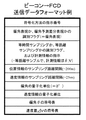
しかし、光ビーコンによる旅行時間の収集は、次のような問題点がある。
(1)図18に示すように、ビーコン20に旅行時間情報を伝えた車両が、交通情報収集のターゲットとする道路Aを通ったのか、それとも道路Bを通ったのか識別できない。
(2)センターで計測できるのは、ビーコン間の所要時間のみであり、その間の交通混雑の粗密状況は把握できない。
(3)ビーコン20に旅行時間情報を伝えた車両が、途中で停車したか否かを判別しにくい。
However, collection of travel time using an optical beacon has the following problems.
(1) As shown in FIG. 18, it is not possible to identify whether the vehicle that has transmitted the travel time information to the
(2) The center can measure only the required time between beacons, and cannot grasp the state of traffic congestion during that time.
(3) It is difficult to determine whether the vehicle that has transmitted the travel time information to the
現状では、統計的手法を用いて、収集した旅行時間データの異常値((1)の道路B通過車両のデータや、(3)の停車車両のデータ)を判定し、それらを除いてターゲットの道路Aの旅行時間を解析しているが、こうした手法を適用するには、多くのデータを集める必要があり、その間に交通状況は刻々と変化するため、従来の方式では、交通状況を迅速、且つ、詳細に把握することが難しい。一方、携帯電話を使用するFCDシステムでは、通信料金の負担が大きな課題となる。 At present, abnormal values of collected travel time data (data of vehicles passing through road B in (1) and data of stopped vehicles in (3)) of the collected travel time data are determined using a statistical method. Although the travel time of road A is analyzed, it is necessary to collect a lot of data to apply such a method, and during that time the traffic situation changes every moment. And it is difficult to grasp in detail. On the other hand, in the FCD system using a mobile phone, the burden of communication charges becomes a major issue.
本発明は、こうした従来の問題点を解決するものであり、ビーコンの特質を生かして車両の走行軌跡データを効率的に収集し、詳しい交通状況を解析することができるFCDシステムを提供し、また、そのシステムを構成する装置を提供することを目的としている。 The present invention solves such a conventional problem, and provides an FCD system capable of efficiently collecting vehicle trajectory data by utilizing characteristics of a beacon and analyzing detailed traffic conditions. It is an object of the present invention to provide an apparatus constituting the system.
そこで、本発明では、ビーコンにより車両の車載機から走行軌跡データを収集するシステムにおいて、下流側ビーコンが走行軌跡データを収集し、この走行軌跡データに基づいて、上流側ビーコンから下流側ビーコンに至る前記車両の走行距離を求め、この走行距離と、上流側ビーコンから下流側ビーコンまでの対象道路の距離とを比較して、前記車両の走行軌跡データを対象道路の交通状況の解析に使用するか否かを判定するように構成している。 Therefore, in the present invention, in a system that collects travel trajectory data from an in-vehicle device of a vehicle by using a beacon, a downstream beacon collects travel trajectory data, and based on the travel trajectory data, a downstream beacon travels from an upstream beacon to a downstream beacon. Determine the travel distance of the vehicle, compare this travel distance with the distance of the target road from the upstream beacon to the downstream beacon, and use the travel locus data of the vehicle to analyze the traffic condition of the target road. It is configured to determine whether or not it is.
また、下流側ビーコンが走行軌跡データを収集し、この走行軌跡データに含まれる位置データを用いて上流側ビーコンから下流側ビーコンに至る前記車両の通過道路区間を特定し、走行軌跡データに含まれる速度データを用いて前記通過道路区間内の速度データの計測地点を補間して特定するように構成している。 In addition, the downstream beacon collects traveling locus data, identifies the passing road section of the vehicle from the upstream beacon to the downstream beacon using the position data included in the traveling locus data, and is included in the traveling locus data. The speed data measurement point in the passing road section is interpolated and specified using the speed data.
また、ビーコンにより車両の車載機から走行軌跡データを収集するFCD収集装置において、走行軌跡データを下流側ビーコンで収集し、この走行軌跡データに基づいて、上流側ビーコンから下流側ビーコンに至る前記車両の走行距離を求め、前記走行距離と、上流側ビーコンから下流側ビーコンまでの対象道路の距離とを比較して、この車両の走行軌跡データを対象道路の交通状況の解析に使用するか否かを判定するように構成している。 Further, in an FCD collection device that collects traveling locus data from an in-vehicle device of a vehicle by using a beacon, the traveling locus data is collected by a downstream beacon, and the vehicle from an upstream beacon to a downstream beacon is collected based on the traveling locus data. The travel distance of the vehicle is compared with the distance of the target road from the upstream beacon to the downstream beacon, and whether or not the travel locus data of the vehicle is used for analyzing the traffic condition of the target road is determined. Is determined.
また、走行軌跡データを下流側ビーコンで収集し、この走行軌跡データに含まれる位置データを用いて上流側ビーコンから下流側ビーコンに至る前記車両の通過道路区間を特定し、この走行軌跡データに含まれる速度データを用いて通過道路区間内の速度データの計測地点を補間して特定するように構成している。 Further, the traveling locus data is collected by the downstream beacon, and the passing road section of the vehicle from the upstream beacon to the downstream beacon is specified using the position data included in the traveling locus data, and is included in the traveling locus data. The speed data measurement points in the passing road section are interpolated and specified using the speed data to be measured.
また、搭載された車両の走行軌跡データをビーコンに送信する車載機において、上流側ビーコンを通過してから計測した走行軌跡データを符号化して下流側ビーコンに送信するように構成している。 Also, in the vehicle-mounted device that transmits the traveling locus data of the mounted vehicle to the beacon, the traveling locus data measured after passing through the upstream beacon is encoded and transmitted to the downstream beacon.
こうした構成により、ビーコンを用いて、車両の走行軌跡データを効率的に収集し、高精度の交通情報を得ることが可能になる。 With such a configuration, it is possible to efficiently collect the traveling locus data of the vehicle using the beacon, and obtain highly accurate traffic information.
(第1の実施形態)
第1の実施形態では、車載機が、一定距離を単位とする単位区間ごとの「平均速度」または「通過時間」を計測し、計測データを下流側ビーコンにアップロードするシステムについて説明する。このシステムでは、図1に示すように、交通情報を収集する対象道路区間に上流側ビーコン10と下流側ビーコン20とが設置されており、対象道路区間におけるビーコン間の距離は既知である。
(1st Embodiment)
In the first embodiment, a description will be given of a system in which the vehicle-mounted device measures an “average speed” or a “passing time” for each unit section in units of a fixed distance, and uploads the measured data to a downstream beacon. In this system, as shown in FIG. 1, an
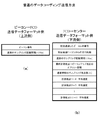
上流側ビーコン10は、通過する車両のFCD車載機に対して、自己のビーコン番号とデータ計測のサンプリング間隔とをダウンロードする。ここでは、図2(a)に示すように、上流側ビーコン10は、サンプリング間隔として、平均速度を計測する単位区間の距離(例えば150m)を指定する。図1では白丸の間を単位区間として表している。
The
車載機は、指定された距離(150m)を走行するごとに単位区間の平均速度を記録し、下流側ビーコン20の位置に来ると、記録した各単位区間の平均速度の情報と前回通過した上流側ビーコン10のビーコン番号とを含む走行軌跡データを下流側ビーコン20にアップロードする。
The in-vehicle device records the average speed of the unit section each time the vehicle travels the designated distance (150 m). The running locus data including the beacon number of the
FCD車載機から下流側ビーコン20に送る走行軌跡データには、図2(b)に示すように、「前回通過したビーコンの番号」「速度のサンプリング距離間隔」「最終計測地点とビーコンアップ地点のオフセット距離(速度の最終計測地点(150mピッチ)と、下流側ビーコン20へのアップロード地点間の距離(150m未満の端数分))」「速度情報のサンプリング地点数」「各単位区間の平均速度」のデータが含まれる。また、送信パス容量に余裕がある場合は、この走行軌跡データの中に「前回通過したビーコンからの走行距離」を含めても良い。しかし、それを含めなくても、下流側ビーコン20は、「速度のサンプリング距離間隔」「速度情報のサンプリング地点数」及び「最終計測地点とビーコンアップ地点のオフセット距離」から「前回通過したビーコンからの走行距離」を算出することができる。
As shown in FIG. 2B, the traveling locus data transmitted from the on-board FCD to the
下流側ビーコン20またはそれに接続するセンター機器は、対象道路区間のビーコン間の距離が分かっているので、この距離と、走行軌跡データから求めた「前回通過したビーコンからの走行距離」とを比較して、車載機を搭載した車両が対象道路区間を通過したのか迂回路を通過したのかを判定する。迂回路を通過した車両から収集した走行軌跡データは、対象道路区間の交通状況を判断する材料から除外する。
The
また、個々の車両の走行軌跡データにおける各単位区間の平均速度を比較し、平均速度が他の区間と比べて異常に遅い区間では、その車両が停車していたものと判定する。この場合には、停車区間とその周辺区間(=加減速に要する区間)のデータを対象道路区間の交通状況を判断する材料から除外する。そして、収集したデータの中から、これらのデータを除いた残りの走行軌跡データを統計的に解析し、各単位区間の平均速度から、対象道路区間内の交通混雑の粗密を分析する。 Further, the average speed of each unit section in the travel locus data of each vehicle is compared, and it is determined that the vehicle has stopped in a section in which the average speed is abnormally slower than other sections. In this case, the data of the stopped section and its surrounding section (= section required for acceleration / deceleration) are excluded from the material for determining the traffic condition of the target road section. Then, from the collected data, the remaining travel trajectory data excluding these data is statistically analyzed, and the density of traffic congestion in the target road section is analyzed from the average speed of each unit section.
このように、このシステムでは、迂回路を通過した車両や停止した車両を的確に判定することができ、これらのデータを除外して、対象道路区間の交通状況を正確、且つ、詳細に分析することができる。 As described above, in this system, the vehicle that has passed the detour or the vehicle that has stopped can be accurately determined, and the traffic condition of the target road section is analyzed accurately and in detail by excluding these data. be able to.
なお、車載機は、単位区間の平均速度を計測する代わりに、単位区間の通過に要した「通過時間」を計測しても良い。下流側ビーコン20またはそれに接続するセンター機器の側で、この「通過時間」と「速度のサンプリング距離間隔」とを用いて単位区間の平均速度を算出することができるからである。
Note that the in-vehicle device may measure the “passing time” required for passing through the unit section, instead of measuring the average speed in the unit section. This is because the
また、各単位区間の平均速度に代えて、各単位区間を走行するごとに速度を測定し、走行軌跡データには、この速度を含めるようにしても良い。 Instead of the average speed of each unit section, the speed may be measured each time the vehicle travels in each unit section, and this speed may be included in the traveling locus data.
また、ここでは「速度のサンプリング距離間隔」として150mを例示したが、50〜300m程度に設定しても良い。このサンプリング距離間隔は、ビーコン間の距離が短い都市部では短く、ビーコン間の距離が長い山間部等では長く設定した方が、対象道路区間の交通状況を知るための走行軌跡データを効率的に集めることができ、ビーコンから車載機にサンプリング間隔の指示情報を送信することにより、ビーコンの設置状況に応じた単位区間の設定が可能になる。また、車載機が走行地域を識別してサンプリング間隔を自ら決めるようにしても良い。この場合、図2(a)のダウンロードデータには、ビーコン番号だけが含まれることになる。 Although 150 m is exemplified as the “speed sampling distance interval” here, it may be set to about 50 to 300 m. This sampling distance interval is shorter in urban areas where the distance between beacons is shorter, and longer in mountainous areas where the distance between beacons is longer. By collecting the information and transmitting the instruction information of the sampling interval from the beacon to the in-vehicle device, it becomes possible to set the unit section according to the installation state of the beacon. Alternatively, the on-vehicle device may identify the traveling area and determine the sampling interval by itself. In this case, only the beacon number is included in the download data of FIG.
(第2の実施形態)
第2の実施形態では、車載機が、一定時間を単位とする単位時間ごとの「平均速度」または「移動距離」を計測し、計測データを下流側ビーコンにアップロードするシステムについて説明する。
このシステムでは、図3に示すように、上流側ビーコン10は、通過する車両のFCD車載機に対して、自己のビーコン番号と、サンプリング間隔としての単位時間(2〜30秒程度)とをダウンロードする。
(Second embodiment)
In the second embodiment, a description will be given of a system in which the in-vehicle device measures an “average speed” or a “moving distance” per unit time in units of a fixed time, and uploads the measured data to a downstream beacon.
In this system, as shown in FIG. 3, the
車載機は、指定された単位時間が経過するごとに平均速度を記録し、下流側ビーコン20の位置に来ると、「前回通過したビーコンの番号」「速度のサンプリング時間間隔」「最終計測地点とビーコンアップ地点のオフセット距離」「速度情報のサンプリング地点数」及び「各単位時間の平均速度」のデータを含む走行軌跡データを下流側ビーコン20にアップロードする。
The in-vehicle device records the average speed every time the specified unit time elapses, and when it comes to the position of the
この場合、送信パス容量に余裕があるときは、この走行軌跡データの中に「前回通過したビーコンからの走行距離」を含めても良い。しかし、それを含めなくても、下流側ビーコン20は、(「速度のサンプリング時間間隔」×「各単位時間の平均速度」)の累積値に「最終計測地点とビーコンアップ地点のオフセット距離」を加算して「前回通過したビーコンからの走行距離」を算出することができる。
In this case, when there is a margin in the transmission path capacity, the traveling locus data may include “the traveling distance from the beacon that passed last time”. However, even if it is not included, the
下流側ビーコン20またはそれに接続するセンター機器は、第1の実施形態と同様に、対象道路区間のビーコン間の距離と、走行軌跡データから求めた「前回通過したビーコンからの走行距離」とを比較して迂回路を通過した車両を判定し、該当する車両の走行軌跡データを、対象道路区間の交通状況を判断する材料から除外する。
Like the first embodiment, the
また、個々の車両の走行軌跡データにおける各単位時間の平均速度を比較し、平均速度が他の単位時間と比べて異常に遅い区間では、その車両が停車していたものと判定し、そのデータを対象道路区間の交通状況を判断する材料から除外する。そして、収集したデータの中から、これらのデータを除いた残りの走行軌跡データを統計的に解析し、各単位時間の平均速度から、対象道路区間内の交通混雑の粗密を分析する。 In addition, the average speed of each unit time in the traveling locus data of each vehicle is compared, and in a section where the average speed is abnormally slower than other unit times, it is determined that the vehicle has stopped, and the data is determined. Is excluded from the material for determining the traffic condition of the target road section. Then, from the collected data, the remaining traveling trajectory data excluding these data is statistically analyzed, and the density of traffic congestion in the target road section is analyzed from the average speed of each unit time.
なお、車載機は、単位時間の平均速度を計測する代わりに、単位時間の「移動距離」(=単位時間×平均速度)を計測しても良い。また、「速度のサンプリング時間間隔」については、第1の実施形態と同様に、可変することができる。 Note that the in-vehicle device may measure the “moving distance” (= unit time × average speed) per unit time instead of measuring the average speed per unit time. Further, the “speed sampling time interval” can be changed similarly to the first embodiment.
(第3の実施形態)
第3の実施形態では、車載機からビーコンにアップロードする平均速度、通過時間あるいは移動距離のデータのデータ量を削減する方法について説明する。ここでは、速度情報を例に取る。
(Third embodiment)
In the third embodiment, a method for reducing the data amount of average speed, transit time, or moving distance data uploaded from a vehicle-mounted device to a beacon will be described. Here, speed information is taken as an example.
データ量の削減は、速度情報を統計的に偏りを持つデータに変換し、変換後のデータを、符号表を用いて可変長符号化することにより行う。この手法については、本発明の発明者が先に提案した特願2001−329242号等に詳述している。 The data amount is reduced by converting the speed information into statistically biased data, and performing variable-length coding on the converted data using a code table. This technique is described in detail in Japanese Patent Application No. 2001-329242 previously proposed by the inventor of the present invention.
統計的に偏りを持つデータに変換するため、例えば、計測値を前回の計測値との差分で表現する。こうすることにより、車両が対象道路区間内を略均一の速度で通過する場合に、差分速度データは0付近に集中する。 In order to convert the data into data having a statistical bias, for example, the measured value is represented by a difference from the previous measured value. Thus, when the vehicle passes through the target road section at a substantially uniform speed, the difference speed data concentrates around zero.
一方、符号表では、発生頻度が高い±0付近の差分速度データに小さいビット数の値を割り当て、発生頻度が低い差分速度データに大きいビット数の値を割り当てる。そして、この符号表を用いて差分速度データを可変長符号化することによりデータ量を削減することができる。また、このとき、そこに含まれる連続する同じ値に対してランレングス符号化を適用して連長圧縮することにより、さらにデータ量を削減することができる。 On the other hand, in the code table, a value of a small number of bits is assigned to differential speed data having a high occurrence frequency near ± 0, and a value of a large number of bits is assigned to differential speed data having a low occurrence frequency. Then, the differential rate data is subjected to variable-length encoding using this code table, so that the data amount can be reduced. Also, at this time, by applying run-length coding to the same continuous value included therein and performing run length compression, the data amount can be further reduced.
また、速度データを差分表現する前に、速度データを量子化し、量子化後の値を差分で表現するようにすればデータ量をさらに大幅に削減することができる。この速度データの量子化では、センターで渋滞状況を詳細に把握する必要があるため、遅い速度に対して細かく量子化し、速度が速くなるほど粗く量子化する。
例えば、
0〜1km/h → 1
2〜3km/h → 2
4〜8km/h → 3
9〜18km/h → 4
19〜29km/h → 5
30〜39km/h → 6
40〜49km/h → 7
: :
のように量子化した場合には、速度データが33km/hから次の計測地点で38km/hに変化した場合でも、量子化値の差分は0となり、可変長符号化による圧縮効果が高まる。
If the speed data is quantized before the speed data is expressed as a difference, and the value after quantization is expressed as a difference, the data amount can be further reduced. In the quantization of the speed data, since it is necessary to grasp the traffic congestion state in detail at the center, the quantization is performed finely at a low speed, and coarsely quantized at a higher speed.
For example,
0-1km /
2-3km /
4-8km /
9-18km /
19-29km /
30-39km /
40-49km /
:::
When the quantization is performed as described above, even if the velocity data changes from 33 km / h to 38 km / h at the next measurement point, the difference between the quantization values becomes 0, and the compression effect by the variable length coding increases.
上流側ビーコンまたはそれに接続するセンター機器(即ち、FCD収集装置)は、車載機に対して、符号化の方法、速度情報の量子化単位、符号表をダウンロードし、車載機は、計測した速度データを指示された符号化方法で符号化して下流側ビーコンにアップロードする。 The upstream beacon or the center device connected to the beacon (that is, the FCD collection device) downloads the encoding method, the quantization unit of the speed information, and the code table to the vehicle-mounted device, and the vehicle-mounted device transmits the measured speed data. Is encoded by the designated encoding method and uploaded to the downstream beacon.
図4(a)は、この場合に上流側ビーコン10からダウンロードされるデータを示し、図4(b)は、車載機が下流側ビーコン20にアップロードするデータのデータ構造を示している。図4(a)には、サンプリング間隔、量子化単位及び符号表を指定する符号化指示データが含まれ、また、図4(b)には、速度差分を符号化したデータと、速度差分を速度データに変換するために必要な最終計測地点の絶対速度とが含まれている。
FIG. 4A shows data downloaded from the
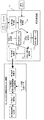
図5は、上流側ビーコン(またはそれに接続するセンター機器)10と、下流側ビーコン(またはそれに接続するセンター機器)20と、FCD車載機50とから成るこのシステムの構成をブロック図で示している。
FIG. 5 is a block diagram showing the configuration of this system including an upstream beacon (or a center device connected thereto) 10, a downstream beacon (or a center device connected thereto) 20, and an FCD vehicle-mounted
上流側ビーコン(またはそれに接続するセンター機器)10は、交通状況を判定する交通状況判定部11と、過去の走行軌跡データから各種の交通状況に応じた符号化指示データ(サンプリング間隔、量子化単位、符号表)を作成する符号化指示作成部12と、通過する車両の車載機50に対して選択した符号化指示データをダウンロードする符号化指示選出部13とを備えている。
The upstream beacon (or a center device connected thereto) 10 includes a traffic
交通状況判定部11は、FCDを含む交通センサ14のセンサ情報を処理するセンサ処理部111と、交通センサの情報から交通状況を判定する交通状況判定部112とを備えている。
The traffic
符号化指示作成部12は、交通状況のパターンに分けた過去の走行軌跡データ123を用いて、各パターンの交通状況における速度データを効率的に符号化できる符号化指示データ(サンプリング間隔、量子化単位、符号表)122を算出する符号表算出部121を備えている。
The encoding
符号化指示選出部13は、交通状況判定部112が判定した交通状況に応じて、符号化指示データ122を選出する符号化指示選出部131と、ビーコン番号管理データ134で管理されているビーコン番号及び選出された符号化指示データをFCD車載機50にダウンロードするビーコン番号/符号化指示送信部133とを備えている。
The encoding
また、FCD車載機50は、上流側ビーコン10から符号化指示データ52を受信するデータ受信部51と、FCD車載機50が予め保持するデフォルトの符号化指示データ53と、速度センサ60の検出データを蓄積する走行軌跡蓄積部54と、走行軌跡蓄積部54に蓄積された計測データを符号化指示データ52または53を用いて符号化する符号化処理部56と、走行軌跡データを下流側ビーコン20に送信する走行軌跡送信部57とを備えている。
The FCD on-
また、下流側ビーコン(またはそれに接続するセンター機器)20は、FCD車載機50から走行軌跡データを受信する走行軌跡受信部21と、上流側ビーコン10及び下流側ビーコン20の設置位置を表すビーコン設置位置データ22と、符号化されている走行軌跡データを復号化する符号化データ復号部24と、対象道路区間以外を走行した車両や停止した車両の走行軌跡データを除外する走行ルート/停車判定部26と、走行軌跡データを交通流動の解析等に利用する走行軌跡情報活用部25とを備えている。
The downstream beacon (or a center device connected thereto) 20 includes a traveling
なお、上流側ビーコン10、下流側ビーコン20及びFCD車載機50の各部の機能は、これらの装置が内蔵するコンピュータにプログラムで規定した処理を行わせることにより実現することができる。
The functions of the respective components of the
このシステムでは、上流側ビーコン10の交通状況判定部11が、FCDを含む交通センサ14のセンサ情報に基づいて交通状況を判定し、符号化指示作成部12と符号化指示選出部13とに伝達する。
In this system, the traffic
符号化指示作成部12は、過去の走行軌跡データ123を、そのときに交通状況判定部11から伝えられた交通状況に応じてパターン分けし、この走行軌跡データ123を用いて、各パターンの交通状況における速度データを符号化するための符号化指示データ(サンプリング間隔、量子化単位、符号表)122を作成する。
The encoding
符号化指示選出部13は、符号化指示作成部12により予め作成された符号化指示データ122の中から、交通状況判定部112が判定した現在の交通状況に適合する符号化指示データ122を選択し、ビーコン番号とともに、通過する車両のFCD車載機50にダウンロードする。また、選出した符号化指示データ122は、下流側ビーコン20にも伝えられる。
The encoding
FCD車載機50は、上流側ビーコン10からビーコン番号と符号化指示データ52とを受信すると、それらを保存し、速度センサ60により検出された走行車両の速度データを収集して走行軌跡蓄積部54に蓄積する。そして、下流側ビーコン20の下を通過するときに、走行軌跡蓄積部54に蓄積された速度データを、符号化指示データ52を用いて符号化し、下流側ビーコン20にアップロードする。なお、上流側ビーコン10から符号化指示データを受信しなかったときは、デフォルトの符号化指示データ53を用いて、この符号化を行う。
Upon receiving the beacon number and the encoded instruction data 52 from the
走行軌跡データを受信した下流側ビーコン20は、符号化されている走行軌跡データを、上流側ビーコン10から通知された符号表を用いて復号化し、この走行軌跡データから求めた「上流側ビーコン10を通過してからの走行距離」とビーコン設置位置データ22で管理するビーコン間の距離とを比較して、このFCD車載機50を搭載した車両が対象道路区間を通過したのか迂回路を通過したのかを判定する。迂回路を通過した車両から収集した走行軌跡データは、対象道路区間の交通状況を判断する材料から除外する。
The
また、走行軌跡データの各単位区間の速度データを比較して、車両が停車していた区間を識別し、その区間のデータも対象道路区間の交通状況を判断する材料から除外する。残るデータを用いて対象道路区間の交通状況を解析し、交通情報に活用する。 Further, the speed data of each unit section of the traveling locus data is compared to identify the section where the vehicle has stopped, and the data of that section is also excluded from the material for determining the traffic condition of the target road section. The remaining data is used to analyze the traffic situation in the target road section and use it for traffic information.
このように、走行軌跡データの符号化により、FCD車載機50から下流側ビーコン20にアップロードするデータのデータ量を削減することができ、車両が下流側ビーコン20の下を通過する短い時間に、走行軌跡データを支障なく伝送することが可能になる。
In this way, by encoding the traveling locus data, the data amount of data to be uploaded from the on-
(第4の実施形態)
第4の実施形態では、FCD車載機が、速度データとともに位置データを計測して、これらのデータを下流側ビーコンにアップロードし、下流側ビーコンが、この位置データに基づいて車両の通過した道路を識別するシステムについて説明する。なお、この実施形態では、上下流ビーコン間の道路のみならず、1つのビーコンがあれば、そのビーコンに至るまでの道路を特定し、交通状況を収集することも可能である。
(Fourth embodiment)
In the fourth embodiment, the on-board FCD measures the position data together with the speed data, uploads these data to the downstream beacon, and the downstream beacon determines the road through which the vehicle has passed based on the position data. The identification system will be described. In this embodiment, if there is one beacon as well as the road between the upstream and downstream beacons, it is possible to specify the road leading to that beacon and collect the traffic situation.
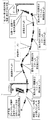
このFCDシステムでは、図6に示すように、FCD車載機が、位置情報を二重丸の地点で計測し、速度情報を、位置情報より密に、二重丸及び白丸の地点で計測する。FCD車載機は、これらの計測データを、下流側ビーコン20の下を通過するときに、下流側ビーコン20にアップロードする。
In this FCD system, as shown in FIG. 6, the FCD in-vehicle device measures the position information at a double circle point, and measures the speed information more densely than the position information at the double circle and white circle points. The FCD vehicle-mounted device uploads these measurement data to the
下流側ビーコン20(またはそれに接続するセンター機器)は、受信した走行軌跡データに含まれる間欠的な位置情報を用いてマップマッチングを行い、車両が通過した道路を特定する。そして、その道路上の位置の間を速度情報を使って補完し、速度情報の計測地点とその地点での速度を特定し、その道路の混雑状況を判定する。 The downstream beacon 20 (or a center device connected thereto) performs map matching using the intermittent position information included in the received travel locus data, and specifies the road on which the vehicle has passed. Then, between the positions on the road is complemented by using the speed information, the measurement point of the speed information and the speed at the point are specified, and the congestion state of the road is determined.
この場合、位置計測地点を密に設ければ、ビーコン側で道路の特定が容易であり、また、位置データから速度を算出することも可能である。しかし、位置データは、速度データに比べて情報量が重いと言う欠点がある。位置情報は、位置の表示を例えば3m単位(分解能を3m)で表したとしても、軌跡位置を表わすために凡そ32ビットが必要である。これに対して、速度情報は、車両の場合、通常、256Km/hを超えることは無いので8ビットで表示することができ、情報量が比較的軽い。 In this case, if the position measurement points are densely provided, the road can be easily specified on the beacon side, and the speed can be calculated from the position data. However, position data has a disadvantage that the amount of information is larger than speed data. Even if the position information is represented in units of, for example, 3 m (resolution is 3 m), the position information requires approximately 32 bits to represent the locus position. On the other hand, in the case of a vehicle, the speed information does not usually exceed 256 km / h, so that it can be displayed in 8 bits, and the amount of information is relatively light.
そのため、位置情報だけで走行状況を表わすよりも、位置情報の数は十分な位置特定精度(マップマッチングによる道路正答率)が得られる程度に止め、この位置情報の間を多数の速度情報で補完した方が、FCD車載機から送る走行軌跡データのデータ量を低く抑えることができ、また、ビーコン側では、走行状況を示す詳細な情報を得ることができる。 For this reason, the number of pieces of position information is limited to a level that provides sufficient position identification accuracy (the rate of correct answers to roads by map matching), rather than representing the driving situation using only the position information. By doing so, the data amount of the traveling locus data sent from the FCD in-vehicle device can be reduced, and the beacon side can obtain detailed information indicating the traveling situation.
FCD車載機50の計測は、原則として、一定時間が経過するごと(定周期方式)、または、一定距離走行するごと(定距離間隔方式)に行う。定周期方式の場合は、長い周期(例えば15秒〜60秒間隔)で位置情報を計測し、短い周期(例えば2秒〜5秒間隔)で速度情報を計測する。また、定距離間隔方式の場合は、長い距離(例えば200m)移動するごとに位置情報を計測し、短い距離(例えば20m)移動するごとに速度情報を計測する。
The measurement of the FCD in-
各計測地点の位置情報は、隣接計測地点からの距離Lと偏角θとで表わし、データ量を減らすため、距離Lは隣接位置計測地点の距離データとの差分ΔLで表現し、また、偏角θは隣接位置計測地点の偏角との差分Δθ(またはθのまま)で表現する。定距離間隔方式の場合には、距離L一定であるため、ΔL=0となり、偏角差分Δθ(または偏角θ)だけで位置を表わすことができる。速度情報Vは、隣接速度計測地点での速度との速度差分ΔVで表わす。また、これらのデータは、可変長符号化や連長圧縮を適用してデータ量の一層の削減を図る。 The position information of each measurement point is represented by the distance L from the adjacent measurement point and the argument θ. To reduce the data amount, the distance L is represented by the difference ΔL from the distance data of the adjacent position measurement point. The angle θ is represented by the difference Δθ (or θ as it is) from the declination of the adjacent position measurement point. In the case of the fixed distance interval method, since the distance L is constant, ΔL = 0, and the position can be represented only by the deviation difference Δθ (or the deviation angle θ). The speed information V is represented by a speed difference ΔV from the speed at the adjacent speed measurement point. In addition, the data amount of these data is further reduced by applying variable-length coding or run-length compression.
このように、位置情報を隣接位置計測地点からの距離Lや偏角θで表現する場合には、これらの位置情報を絶対位置情報に変換するために、最終地点または開始地点の絶対位置情報が必要になるが、ビーコンでFCD車載機の情報収集を行う場合には、ビーコンの位置が既知であるため、FCD車載機がビーコンに対して絶対位置情報をアップロードする必要が無い。そのため、この分だけでも32bit×2+9〜8bitのデータ量の削減が可能になる。 As described above, when the position information is represented by the distance L from the adjacent position measurement point or the declination θ, the absolute position information of the final point or the start point is converted to convert the position information into the absolute position information. Although it becomes necessary, when collecting information on the FCD on-vehicle device using the beacon, the FCD on-vehicle device does not need to upload absolute position information to the beacon because the position of the beacon is known. Therefore, it is possible to reduce the amount of data of 32 bits × 2 + 9 to 8 bits by this amount alone.
図6は、定周期方式の場合の位置計測地点(二重丸)及び速度計測地点(白丸+二重丸)の計測データを示しており、定距離間隔方式では、この位置測定データのΔLが不要になる。 FIG. 6 shows measurement data of a position measurement point (double circle) and a speed measurement point (white circle + double circle) in the case of the fixed period method. It becomes unnecessary.
図7は、上流側ビーコン10がFCD車載機にダウンロードする符号化指示データを例示している。ここには、この符号化方法を特定する指示番号、偏角を偏角のまま表わすか偏角差分で表わすかを指定するフラグ(ここでは偏角表現を指示)、定周期方式か定距離間隔方式かを指定し、計測情報を指示するフラグ(ここでは定距離間隔方式を指示し、計測情報としてθ及びVを指示)、位置情報の計測地点間隔を指定するサンプリング距離間隔(=200m)、速度情報の計測地点間隔を指定するサンプリング距離間隔(=25m)、偏角の量子化単位(=3°)、図8に示す速度情報の量子化単位テーブル、図9(a)に示す偏角θの符号表、及び、図9(b)に示す速度差分ΔVの符号表が指示されている。
FIG. 7 shows an example of the encoding instruction data downloaded by the
また、図10は、FCD車載機から下流側ビーコン20にアップロードされるデータを示している。ここには、FCD車載機が搭載された車両のID情報、符号化指示データに含まれる符号化方法の指示番号、θの計測地点数、偏角θの符号化データ、最終計測位置の速度、ΔVの計測地点数、及び、速度差分の符号化データが含まれている。
FIG. 10 shows data uploaded from the on-board FCD device to the
図11は、このシステムの構成をブロック図で示している。上流側ビーコン(またはそれに接続するセンター機器)10の構成は、第3の実施形態(図5)と実質的に同じである。 FIG. 11 is a block diagram showing the configuration of this system. The configuration of the upstream beacon (or the center device connected thereto) 10 is substantially the same as that of the third embodiment (FIG. 5).
また、FCD車載機50は、上流側ビーコン10から符号化指示データ52を受信する符号化指示受信部51と、FCD車載機50が予め保持するデフォルトの符号化指示データ53と、GPSアンテナ58及びジャイロ59を用いて自車位置を計測する自車位置判定部55と、自車位置の計測データ及び速度センサ60の検出データを蓄積する走行軌跡蓄積部54と、走行軌跡蓄積部54に蓄積された計測データを符号化指示データ52または53を用いて符号化する符号化処理部56と、走行軌跡データを下流側ビーコン20に送信する走行軌跡送信部57とを備えている。
Further, the FCD in-
また、下流側ビーコン(またはそれに接続するセンター機器)20は、FCD車載機50から走行軌跡データを受信する走行軌跡受信部21と、上流側ビーコン10及び下流側ビーコン20の設置位置を表すビーコン設置位置データ22と、ビーコン位置情報を走行軌跡データに加えるビーコン情報加算部23と、符号化されている走行軌跡データを復号化する符号化データ復号部24と、復号化された走行軌跡データを交通流動の解析等に利用する走行軌跡情報活用部25とを備えている。
The downstream beacon (or a center device connected thereto) 20 includes a traveling
図12は、上流側ビーコンが接続するセンター機器(FCD収集装置)10の符号化指示作成部12の処理手順を示している。 まず、N=1のビーコンNを対象として(ステップ1)、ビーコンN周辺での過去の軌跡や代表的な交通状況を収集し(ステップ2)、誤マッチング発生状況や情報量から、位置情報のサンプリング距離間隔Lを決定する(ステップ3)。次に、交通状況や情報量から速度情報の量子化単位を決定し(ステップ4)、交通状況や情報量から速度情報のサンプリング距離間隔を決定する(ステップ5)。次に、統計値算出式に従い、各区間のΔθjを算出し、Δθjの分布を計算して符号表を作成する(ステップ6)。また、統計値算出式に従い、ΔViを算出し、ΔViの分布を計算して符号表を作成する(ステップ7)。決定した量子化単位、計測間隔及び符号表の内容を上流側ビーコン番号の送出指示内容として保存する(ステップ8)。この処理を全てのビーコンについて実施する(ステップ9、10)。
FIG. 12 shows a processing procedure of the encoding
図13は、上流側ビーコン(またはそれに接続するセンター機器)10、下流側ビーコン(またはそれに接続するセンター機器)20及びFCD車載機50の動作手順を示している。まず、上流側ビーコン10は、現在の交通情報を収集し(ステップ11)、送出する量子化単位・計測間隔・符号表を決定し(ステップ12)、符号化指示番号とともにFCD車載機50に送出する(ステップ13)。
FIG. 13 shows the operation procedure of the upstream beacon (or the center device connected thereto) 10, the downstream beacon (or the center device connected thereto) 20, and the FCD in-
FCD車載機50は、符号表を受信し(ステップ14)、指定内容に従い、現在位置・速度情報を計測し、走行軌跡データを蓄積する(ステップ15)。下流側ビーコン20との通信が始まると(ステップ16)、符号表を参照し、走行軌跡データ(位置及び速度)を符号化し(ステップ17)、符号化指示番号と走行軌跡データとを下流側ビーコン20に送信する(ステップ18)。
The FCD in-
下流側ビーコン20は、走行軌跡データを受信すると(ステップ19)、情報を受信したビーコン位置の絶対緯度経度・絶対方位を走行軌跡データに付加し(ステップ20)、符号化指示番号から、量子化単位・計測間隔・符号表を参照し、位置(L/θ)・速度(V)を復号化する(ステップ21)。次に、位置情報を用いてマップマッチングを実施し、道路区間を特定し(ステップ22)、特定した道路区間の間を速度情報で補完して(ステップ23)、交通情報の生成・蓄積等、FCD情報の活用処理を実施する(ステップ24)。
Upon receiving the travel locus data (step 19), the
このように、このシステムでは、FCD車載機を搭載した車両が通過した道路を特定して、この道路でFCD車載機により計測されたデータを交通状況の解析に使用することができる。 As described above, in this system, the road on which the vehicle equipped with the on-board FCD is passed can be specified, and the data measured by the on-board FCD on this road can be used for analyzing the traffic situation.
なお、ここでは、上流側ビーコンに接続するセンター機器が符号化指示内容をあらかじめ複数パターン作成しておく方法について記述したが、センター装置に十分なCPUパワーがある場合には、直近の情報からリアルタイムに符号化指示内容を算出するようにしても良い。 Here, a method has been described in which the center device connected to the upstream beacon prepares a plurality of patterns of coding instruction contents in advance, but if the center device has sufficient CPU power, real-time The encoding instruction content may be calculated first.
(第5の実施形態)
第5の実施形態では、FCD車載機が、予め複数の符号表を保持し、走行状況に応じて自動的に符号表を選出するシステムについて説明する。
(Fifth embodiment)
In the fifth embodiment, a description will be given of a system in which the on-board FCD holds a plurality of code tables in advance and automatically selects a code table according to a traveling situation.
このFCD車載機は、図14に示すように、サンプリング間隔、量子化単位及び符号表が記述された複数の符号化指示データ52と、これらの符号化指示データ52の中から、使用する符号化指示データ52を選出する符号指示選出部61とを備えている。 As shown in FIG. 14, the on-vehicle FCD includes a plurality of coding instruction data 52 in which a sampling interval, a quantization unit, and a code table are described. A code instruction selecting unit 61 for selecting the instruction data 52 is provided.
符号指示選出部61は、過去の走行パターンから、最も適した符号化指示データ52を選出する(処理A)。例えば、あらかじめ決められた距離(数km)を走行する間に、単位距離(100m)当たり偏角θ(またはθ±90°)の絶対値を加算し、その累積値によってランク分けする。このランクは、交差点等が多い都市部では高くなり、山間部では低くなる。また、この走行の間に、単位時間当たりの速度差ΔVの絶対値を加算し、その累積値によってランク分する。このランクは、渋滞が多い都市部では高くなり、山間部では低くなる。そして、この2つのランクの組み合わせにより、選出する符号指示データ52を決定する。その結果、走行地域に応じた符号表を選出することができる。 The code instruction selecting unit 61 selects the most suitable encoding instruction data 52 from the past running patterns (process A). For example, while traveling a predetermined distance (several kilometers), the absolute value of the declination θ (or θ ± 90 °) per unit distance (100 m) is added, and ranking is performed based on the accumulated value. This rank is higher in urban areas where there are many intersections and the like, and lower in mountainous areas. Also, during this traveling, the absolute value of the speed difference ΔV per unit time is added, and the accumulated value is used to divide the rank. This rank is higher in urban areas with heavy traffic and lower in mountainous areas. Then, the code instruction data 52 to be selected is determined based on the combination of the two ranks. As a result, a code table according to the traveling area can be selected.
また、このとき、符号指示選出部61は、過去のアップリンク頻度も考慮に入れて符号化指示データ52を決定するようにしても良い(アップリンク頻度が多い場合には、密な測定を指示する符号化指示データ52を選出する)。 Further, at this time, the code instruction selecting unit 61 may determine the encoding instruction data 52 in consideration of the past uplink frequency (when the uplink frequency is high, an instruction for dense measurement is issued. The encoding instruction data 52 to be executed is selected).
また、図15に示すFCD車載機50は、異なる符号化指示データ521、522に基づいて並行して符号化処理を行う複数の符号化処理部561,562と、各符号化処理部561,562が符号化したデータの中から送信する符号化データを選出する符号化情報選出部62とを備えている。
Further, the on-
符号化処理部561,562は、N個の符号化指示データ521,522を保持している場合に、走行軌跡蓄積部54に蓄積されたデータを各符号化指示データ521,522に基づいて符号化し、N通りの符号化データを生成する。
When holding the N pieces of encoding
符号化情報選出部62は、このN通りの符号化データの中から、情報量とデータサイズとのバランスが取れた最も効果的な符号化データを選出する。符号化情報選出部62は、例えば次のような方法で、効果的な符号化情報であるか否かの判定を行う(処理B)。 The coded information selection unit 62 selects the most effective coded data having a good balance between the information amount and the data size from the N coded data. The coded information selecting unit 62 determines whether or not the coded information is effective coded information, for example, by the following method (process B).
前回走行軌跡データを送信した際にバッファがクリアされているので、今回走行軌跡データ送信する際には、前回送信時から今回の間に、走行軌跡データが「バッファの容量(=通信容量)に既に達した」か「バッファ容量に達していないか」のいずれかである。 Since the buffer was cleared when the previous traveling locus data was transmitted, when the current traveling locus data is transmitted, the traveling locus data is stored in the buffer capacity (= communication capacity) between the previous transmission and the current transmission. Either has already reached "or" the buffer capacity has not been reached ".
「バッファの容量に達した場合」は、できるだけ長い距離の走行軌跡情報を送ることが望ましいので、規定データ量内で一番長い距離を表現できる符号化軌跡情報を送る。また、「バッファ容量に達していない場合」には、できるだけ詳しい情報を送りたいので、規定データ量内で一番サンプリング間隔の短い符号化軌跡情報を送る。こうしたアルゴリズムにより、FCD車載機は、最適な符号表を用いて符号化した走行軌跡データを効果的に送信することができる。 In the case of "when the buffer capacity is reached", it is desirable to send the travel trajectory information as long as possible, so the coded trajectory information that can represent the longest distance within the specified data amount is sent. In addition, when "the buffer capacity has not been reached", it is desirable to send as detailed information as possible, so that encoded trajectory information with the shortest sampling interval within the specified data amount is sent. With such an algorithm, the FCD in-vehicle device can effectively transmit the traveling locus data encoded using the optimal code table.
図16は、この場合のFCD車載機50の処理手順を示している。FCD車載機50は、受信した複数の符号表を保持し(ステップ34)、指定内容に従い、現在位置・速度情報を計測し、走行軌跡データを蓄積する(ステップ35)。下流側ビーコン20との通信が始まると(ステップ36)、最適な符号化指示データを選択するための前記処理Aを行う(ステップ37)。あるいは、各符号化指示データに基づいて符号化したデータの中から効果的な符号化データを選択するための前記処理Bを行う(ステップ38)。次いで、符号化指示番号と符号化した走行軌跡データとを下流側ビーコン20に送信し(ステップ39)、走行軌跡バッファをクリアする(ステップ40)。
FIG. 16 shows a processing procedure of the FCD vehicle-mounted
このように、このシステムでは、FCD車載機が走行状況に応じて、自動的に符号表を選出することができる。また、上流側ビーコンがFCD車載機に送信する符号化指示データの中で、FCD車載機が停車回数や停車時間の情報を上げて来るように指示したり、ウインカー/ハザード/半ドア警告/パーキングブレーキ等の車両センサ情報を上げて来るように指示したりしても良い。これらの情報は、収集した走行軌跡データの中で、交通状況を判定する上でノイズとなる質の悪い情報を排除するときの参考になる。 Thus, in this system, the on-board FCD can automatically select the code table according to the running situation. Also, in the encoding instruction data transmitted by the upstream beacon to the FCD on-board unit, the FCD on-board unit instructs to increase information on the number of stops and the stop time, and turns signal / hazard / half door warning / parking. It may be instructed to increase vehicle sensor information such as brakes. These pieces of information serve as references when eliminating poor-quality information that becomes noise in determining traffic conditions in the collected travel path data.
以上の説明から明らかなように、本発明のFCDシステム及びその装置では、ビーコンを用いて、車両の走行軌跡データを効率的に収集し、高精度の交通情報を得ることが可能になる。 As is clear from the above description, the FCD system and the apparatus of the present invention can efficiently collect the traveling trajectory data of the vehicle using the beacon, and obtain highly accurate traffic information.
また、この走行軌跡データの収集位置が、固定されたビーコンの設置位置であることを利用して、車載機からビーコンに送信するデータのデータ量を削減することができる。 Further, by utilizing the fact that the traveling locus data collection position is the fixed position of the beacon, the amount of data transmitted from the vehicle-mounted device to the beacon can be reduced.
10 上流側ビーコン
11 交通状況判定部
12 符号化指示作成部
13 符号化指示選出部
14 交通センサ
20 下流側ビーコン
21 走行軌跡受信部
22 ビーコン設置位置データ
23 ビーコン情報加算部
24 符号化データ復号部
25 走行軌跡情報活用部
26 走行ルート/停車判定部
50 FCD車載機
51 データ受信部
52 符号化指示データ
53 デフォルトの符号化指示データ
54 走行軌跡蓄積部
55 自車位置判定部
56 符号化処理部
57 走行軌跡送信部
58 GPSアンテナ
59 ジャイロ
60 速度センサ
61 符号指示選出部
62 符号化情報選出部
111 センサ処理部
112 交通状況判定部
121 符号表算出部
122 符号化指示データ
123 走行軌跡データ
131 符号化指示選出部
132 符号化指示送信部
133 ビーコン番号/符号化指示送信部
134 ビーコン番号管理データ
521 符号化指示データ
522 符号化指示データ
561 符号化処理部
562 符号化処理部
10 Upstream beacon
11 Traffic condition judgment section
12 Encoding instruction creation unit
13 Encoding instruction selection section
14 Traffic sensor
20 Downstream beacon
21 Travel locus receiver
22 Beacon location data
23 Beacon information adder
24 Encoded data decoder
25 Travel Track Information Utilization Department
26 Driving route / stop judgment section
50 FCD on-board unit
51 Data receiver
52 Encoding instruction data
53 Default encoding instruction data
54 Travel locus storage unit
55 Own vehicle position judgment unit
56 Coding unit
57 Travel locus transmitter
58 GPS antenna
59 Gyro
60 Speed sensor
61 Code indication selection section
62 Encoding information selector
111 Sensor processing unit
112 Traffic situation judgment section
121 Code table calculator
122 Encoding instruction data
123 Travel locus data
131 Encoding instruction selector
132 Encoding instruction transmitter
133 Beacon number / encoding instruction transmitter
134 Beacon number management data
521 Encoding instruction data
522 Encoding instruction data
561 Encoding unit
562 Encoding unit
Claims (25)
ビーコンが前記走行軌跡データを収集し、前記走行軌跡データに含まれる位置データを用いて前記ビーコンに至る前記車両の通過道路区間を特定し、前記走行軌跡データに含まれる速度データを用いて前記通過道路区間内の前記速度データの計測地点を補間して特定することを特徴とするFCDシステム。 A system that collects travel trajectory data from a vehicle-mounted device using a beacon,
The beacon collects the travel trajectory data, identifies a passing road section of the vehicle reaching the beacon using the position data included in the travel trajectory data, and uses the speed data included in the travel trajectory data to perform the passing. An FCD system for interpolating and specifying a measurement point of the speed data in a road section.
前記走行軌跡データを下流側ビーコンで収集し、前記走行軌跡データに基づいて、上流側ビーコンから前記下流側ビーコンに至る前記車両の走行距離を求め、前記走行距離と、前記上流側ビーコンから前記下流側ビーコンまでの対象道路の距離とを比較して、前記車両の走行軌跡データを前記対象道路の交通状況の解析に使用するか否かを判定することを特徴とするFCD収集装置。 An FCD collection device that collects traveling trajectory data from a vehicle-mounted device by a beacon,
The traveling locus data is collected by a downstream beacon, and based on the traveling locus data, the traveling distance of the vehicle from the upstream beacon to the downstream beacon is determined, and the traveling distance and the downstream distance from the upstream beacon are calculated. An FCD collection device, which determines whether or not the travel locus data of the vehicle is used for analyzing the traffic condition of the target road by comparing the distance of the target road to a side beacon.
前記走行軌跡データを下流側ビーコンで収集し、前記走行軌跡データに含まれる位置データを用いて上流側ビーコンから前記下流側ビーコンに至る前記車両の通過道路区間を特定し、前記走行軌跡データに含まれる速度データを用いて前記通過道路区間内の前記速度データの計測地点を補間して特定することを特徴とするFCD収集装置。 An FCD collection device that collects traveling trajectory data from a vehicle-mounted device by a beacon,
The traveling locus data is collected by a downstream beacon, and a passing road section of the vehicle from the upstream beacon to the downstream beacon is identified using the position data included in the traveling locus data, and is included in the traveling locus data. An FCD collection device for interpolating and specifying a measurement point of the speed data in the passing road section using the speed data obtained.
上流側ビーコンを通過してから計測した前記走行軌跡データを符号化して下流側ビーコンに送信することを特徴とする車載機。 An in-vehicle device that transmits traveling locus data of a mounted vehicle to a beacon,
An in-vehicle device characterized in that the traveling locus data measured after passing through an upstream beacon is encoded and transmitted to a downstream beacon.
Priority Applications (1)
| Application Number | Priority Date | Filing Date | Title |
|---|---|---|---|
| JP2004262344A JP2004342138A (en) | 2004-09-09 | 2004-09-09 | Fcd system and device using beacon |
Applications Claiming Priority (1)
| Application Number | Priority Date | Filing Date | Title |
|---|---|---|---|
| JP2004262344A JP2004342138A (en) | 2004-09-09 | 2004-09-09 | Fcd system and device using beacon |
Related Parent Applications (1)
| Application Number | Title | Priority Date | Filing Date |
|---|---|---|---|
| JP2002174424A Division JP3748420B2 (en) | 2002-06-14 | 2002-06-14 | FCD system and apparatus using beacon |
Publications (2)
| Publication Number | Publication Date |
|---|---|
| JP2004342138A true JP2004342138A (en) | 2004-12-02 |
| JP2004342138A5 JP2004342138A5 (en) | 2005-09-22 |
Family
ID=33536076
Family Applications (1)
| Application Number | Title | Priority Date | Filing Date |
|---|---|---|---|
| JP2004262344A Withdrawn JP2004342138A (en) | 2004-09-09 | 2004-09-09 | Fcd system and device using beacon |
Country Status (1)
| Country | Link |
|---|---|
| JP (1) | JP2004342138A (en) |
Cited By (10)
| Publication number | Priority date | Publication date | Assignee | Title |
|---|---|---|---|---|
| JP2006344006A (en) * | 2005-06-09 | 2006-12-21 | Sumitomo Electric Ind Ltd | Travel time estimation system, apparatus, and method |
| JP2007034675A (en) * | 2005-07-27 | 2007-02-08 | Mitsubishi Electric Corp | Traveling time measurement and notification system |
| JP2009093590A (en) * | 2007-10-12 | 2009-04-30 | Kenwood Corp | Road traffic information providing system, road traffic information providing device, and road traffic information providing method and program |
| JP2011039704A (en) * | 2009-08-07 | 2011-02-24 | Sumitomo Electric Ind Ltd | Processing apparatus for probe information, computer program, and road-vehicle communication system |
| JP2014109950A (en) * | 2012-12-03 | 2014-06-12 | Fujitsu Ltd | System, program and method for processing probe information |
| CN104252793A (en) * | 2013-06-27 | 2014-12-31 | 比亚迪股份有限公司 | Signal lamp state detecting method, signal lamp state detecting system and vehicle-mounted control device |
| JP2016033703A (en) * | 2014-07-31 | 2016-03-10 | アイシン・エィ・ダブリュ株式会社 | Bad road determination system, method and program |
| JP2017111813A (en) * | 2015-12-17 | 2017-06-22 | インターナショナル・ビジネス・マシーンズ・コーポレーションInternational Business Machines Corporation | Method, computer readable storage medium and system for generating uncertainty-based traffic congestion index |
| JP2020166268A (en) * | 2019-03-29 | 2020-10-08 | バイドゥ オンライン ネットワーク テクノロジー (ベイジン) カンパニー リミテッド | Method for determining quality of map trajectory matching data, device, server and medium |
| CN117356546A (en) * | 2023-12-01 | 2024-01-09 | 南京禄口国际机场空港科技有限公司 | Control method, system and storage medium of spraying vehicle for airport lawn |
-
2004
- 2004-09-09 JP JP2004262344A patent/JP2004342138A/en not_active Withdrawn
Cited By (12)
| Publication number | Priority date | Publication date | Assignee | Title |
|---|---|---|---|---|
| JP2006344006A (en) * | 2005-06-09 | 2006-12-21 | Sumitomo Electric Ind Ltd | Travel time estimation system, apparatus, and method |
| JP2007034675A (en) * | 2005-07-27 | 2007-02-08 | Mitsubishi Electric Corp | Traveling time measurement and notification system |
| JP2009093590A (en) * | 2007-10-12 | 2009-04-30 | Kenwood Corp | Road traffic information providing system, road traffic information providing device, and road traffic information providing method and program |
| JP2011039704A (en) * | 2009-08-07 | 2011-02-24 | Sumitomo Electric Ind Ltd | Processing apparatus for probe information, computer program, and road-vehicle communication system |
| JP2014109950A (en) * | 2012-12-03 | 2014-06-12 | Fujitsu Ltd | System, program and method for processing probe information |
| CN104252793A (en) * | 2013-06-27 | 2014-12-31 | 比亚迪股份有限公司 | Signal lamp state detecting method, signal lamp state detecting system and vehicle-mounted control device |
| JP2016033703A (en) * | 2014-07-31 | 2016-03-10 | アイシン・エィ・ダブリュ株式会社 | Bad road determination system, method and program |
| JP2017111813A (en) * | 2015-12-17 | 2017-06-22 | インターナショナル・ビジネス・マシーンズ・コーポレーションInternational Business Machines Corporation | Method, computer readable storage medium and system for generating uncertainty-based traffic congestion index |
| JP2020166268A (en) * | 2019-03-29 | 2020-10-08 | バイドゥ オンライン ネットワーク テクノロジー (ベイジン) カンパニー リミテッド | Method for determining quality of map trajectory matching data, device, server and medium |
| JP7082151B2 (en) | 2019-03-29 | 2022-06-07 | バイドゥ オンライン ネットワーク テクノロジー(ペキン) カンパニー リミテッド | Map trajectory matching data quality determination method, equipment, server and medium |
| CN117356546A (en) * | 2023-12-01 | 2024-01-09 | 南京禄口国际机场空港科技有限公司 | Control method, system and storage medium of spraying vehicle for airport lawn |
| CN117356546B (en) * | 2023-12-01 | 2024-02-13 | 南京禄口国际机场空港科技有限公司 | Control method, system and storage medium of spraying vehicle for airport lawn |
Similar Documents
| Publication | Publication Date | Title |
|---|---|---|
| JP4633505B2 (en) | Traffic information generating device, traffic information generating method, traffic information providing device, and traffic information distribution system | |
| JP5649726B2 (en) | How to determine cross-failure information | |
| CN107784835B (en) | Traffic state mode prediction system based on traffic data analysis and prediction method thereof | |
| US11740101B2 (en) | Method for characterising bends for warning drivers | |
| US8260532B2 (en) | Traffic probe in-vehicle map-based process to reduce data communications and improve accuracy | |
| KR20050084501A (en) | Traffic information providing system, traffic information expression method and device | |
| EP1566665A1 (en) | Apparatus and method for providing ambient parameter data and for determining weather information | |
| JP2004280521A (en) | Method and device for transmitting traveling track in probe car system | |
| CN101958043A (en) | Highway section calculation element hourage and method thereof | |
| US6329932B1 (en) | Method for determining traffic data and traffic information exchange | |
| JP4233364B2 (en) | Traffic information transmission method, traffic information transmission system and apparatus | |
| GB2361545A (en) | Traffic monitoring | |
| JP3748420B2 (en) | FCD system and apparatus using beacon | |
| CN109377758B (en) | Method and system for estimating running time | |
| JP2004220574A (en) | Expression method of road-related information, device and system for implementing the same | |
| JP2004342138A (en) | Fcd system and device using beacon | |
| JP2004333157A (en) | Method and device for transmitting route information | |
| US20070233359A1 (en) | System and method for aggregating probe vehicle data | |
| JP2006344006A (en) | Travel time estimation system, apparatus, and method | |
| KR100515203B1 (en) | System and Method for Providing Traffic Information using Node Selection Technique | |
| KR101572582B1 (en) | Navigation apparatus, traffic prediction service apparatus, traffic prediction service system and its method | |
| WO2005038742A1 (en) | Method and device for generating traffic information | |
| JP2004318621A (en) | Traffic information estimation device and method | |
| CN102692233B (en) | Variable message sign application system, electronic navigation apparatus and method | |
| JP2006031422A (en) | Device and method for generating traffic information, device for providing traffic information and system for distributing same |
Legal Events
| Date | Code | Title | Description |
|---|---|---|---|
| A521 | Written amendment |
Effective date: 20050613 Free format text: JAPANESE INTERMEDIATE CODE: A523 |
|
| A621 | Written request for application examination |
Free format text: JAPANESE INTERMEDIATE CODE: A621 Effective date: 20050613 |
|
| RD04 | Notification of resignation of power of attorney |
Effective date: 20060327 Free format text: JAPANESE INTERMEDIATE CODE: A7424 |
|
| A761 | Written withdrawal of application |
Free format text: JAPANESE INTERMEDIATE CODE: A761 Effective date: 20070614 |