JP2004340407A - Ventilating device - Google Patents
Ventilating device Download PDFInfo
- Publication number
- JP2004340407A JP2004340407A JP2003134334A JP2003134334A JP2004340407A JP 2004340407 A JP2004340407 A JP 2004340407A JP 2003134334 A JP2003134334 A JP 2003134334A JP 2003134334 A JP2003134334 A JP 2003134334A JP 2004340407 A JP2004340407 A JP 2004340407A
- Authority
- JP
- Japan
- Prior art keywords
- damper
- air
- sub
- shutter
- opening
- Prior art date
- Legal status (The legal status is an assumption and is not a legal conclusion. Google has not performed a legal analysis and makes no representation as to the accuracy of the status listed.)
- Granted
Links
- 238000007664 blowing Methods 0.000 claims description 24
- 238000009423 ventilation Methods 0.000 claims description 23
- 210000000078 claw Anatomy 0.000 claims description 7
- 238000010438 heat treatment Methods 0.000 abstract description 21
- 238000001035 drying Methods 0.000 abstract description 20
- 238000007599 discharging Methods 0.000 abstract 1
- 238000010586 diagram Methods 0.000 description 12
- 238000009833 condensation Methods 0.000 description 1
- 230000005494 condensation Effects 0.000 description 1
- 230000000694 effects Effects 0.000 description 1
- 230000000630 rising effect Effects 0.000 description 1
Images

Landscapes
- Air-Flow Control Members (AREA)
- Accessory Of Washing/Drying Machine, Commercial Washing/Drying Machine, Other Washing/Drying Machine (AREA)
Abstract
Description
【0001】
【発明の属する技術分野】
この発明は、例えば浴室などの室内の換気を行う換気装置に関する。
【0002】
【従来の技術】
従来から、浴室の空気を吸気する吸気口と、吸気した空気を外へ排気する排気口と、吸気した空気を前記浴室へ戻す吹出口と、前記吸気口から空気を吸気して送風する送風機と、この送風機から送風される空気の送風方向を前記排気口や吹出口に切り換えるダンパーと、前記吹出口から吹き出す空気を加熱するヒータとを備えた浴室用の換気装置が知られている(特許文献1参照)。
【0003】
かかる換気装置は、換気モードのときダンパーを第1位置に位置して吹出口を閉じるとともに吸気口から吸気した空気を排気口から排気することにより浴室の換気を行うものである。また、暖房モードのときダンパーを第2位置に位置させて排気口を閉じるとともに吸気口から吸気した空気をヒータにより加熱し、この加熱した空気を吹出口から吹き出させて浴室の暖房を行うものである。
【0004】
ところで、洗濯した衣類を浴室に干して乾かす場合、換気装置を暖房モードにすればよいが、この暖房モードでは、浴室の空気をヒータで加熱して循環させていくだけなので、浴室の湿気を取り除くことができず、このため衣類の乾燥を効率よく行うことができない。
【0005】
そこで、暖房モードと乾燥モードを交互に繰り返すことによって浴室の湿気を取り除くようにしたものが提案されている。
【0006】
また、ダンパーを第1位置と第2位置との中間位置に位置させ、浴室の暖房を行いながら吸気口から吸気した空気の一部を排気口から排気させて浴室の湿気を外に排出させることにより浴室の湿気を取り除くようにした換気装置がある。
【0007】
【特許文献1】
特開平9−126516号公報(第3頁、図1)
【0008】
【発明が解決しようとする課題】
しかしながら、前者の場合、換気モードのとき暖房モードで暖めた空気を排気してしまうので、この換気モードの際には浴室を暖めることができず、このため衣類の乾燥に長時間要してしまう。また、暖めた空気を排気してしまうことにより暖房効率が非常に悪いという問題がある。さらに、暖房モードのとき湿気を取り除くことができないので結露してしまう虞がある。
【0009】
後者の場合、ダンパーの中間位置によって排気口から排気される排気風量や循環される循環風量が決定されるが、ダンパーの部品公差や取り付け誤差等によってダンパーの先端位置が予め設定した設定位置から数mm(=A)ずれが生じてしまう。さらに、ダンパーの位置を検知する近接センサーによるダンパーの先端位置のずれが数mm(=B)生じ、合計として設定位置から約±(A+B)mmの誤差が生じてしまう。このため、製品毎による排気風量や循環風量のバラツキが大きくなってしまい、乾燥に要する時間が製品毎に大きく異なってしまう。また、ダンパーを中間位置に停止させるため、このダンパー位置が安定せず送風機から送られてくる風によってダンパーがその中間位置で振動し、このためガタツキ音が発生するという問題がある。
【0010】
この発明の目的は、短時間で衣類等の乾燥を行うことができるとともに、製品毎による排気風量や循環風量のバラツキを小さくすることができ、さらにガタツキ音が発生しない換気装置を提供することにある。
【0011】
【課題を解決するための手段】
上記目的を達成するため、請求項1の発明は、室内の空気を吸気する吸気口と、吸気した空気を外へ排気する排気口と、吸気した空気を前記室内へ戻す吹出口と、前記吸気口から空気を吸引して送風する送風手段と、この送風手段から送風される空気を前記排気口へ案内する第1位置と前記吹出口へ案内する第2位置とに切り換わるダンパーと、前記吹出口から吹き出す空気を加熱するヒータとを備えた換気装置であって、
前記ダンパーが第2位置に切り換わっているとき、前記送風手段から送風される空気の一部を前記排気口へ送り出すことが可能な送出手段を設けたことを特徴とする。
【0012】
また、前記室内を乾燥する乾燥モードが設定されているとき、前記ヒータがオンされるとともに前記サブダンパーが開成されることを特徴とする。
【0013】
請求項2の発明は、前記送出手段は、前記ダンパーに設けた開口と、この開口を開閉するサブダンパーと、このサブダンパーを開閉する開閉手段とを備え、
この開閉手段は、予め設定した順序で前記送風手段のオン・オフ動作とダンパーの切換動作とを行うことによってサブダンパーを開閉することを特徴とする。
【0014】
請求項3の発明は、前記開閉手段は、サブダンパーを閉成する方向に付勢する付勢部材と、前記サブダンパーを閉成した位置に固定し且つダンパーが第1位置と第2位置との間の所定位置にきたときのみにサブダンパーの固定解除するロック部材とを有し、
前記サブダンパーは、ロック部材による固定が解除された際に前記送風手段の風圧によって前記付勢部材の付勢力に抗して開成し、
この開成したサブダンパーは、前記送風手段が停止した際に前記付勢部材により閉成し、前記ダンパーが所定位置から第1位置または第2位置へ移動するとき、閉成したサブダンパーを前記ロック部材が固定することを特徴とする。
【0015】
また、前記送出手段は、ダンパーが第2位置に位置しているとき前記送風手段から送風される空気の一部を前記排気口へ案内するバイパス風路と、このバイパス風路を開閉するシャッターとを有していることを特徴とする。
【0016】
請求項4の発明は、前記送出手段は、ダンパーが第2位置に位置しているとき前記送風手段から送風される空気の一部を前記排気口へ案内するバイパス風路と、このバイパス風路を開閉するシャッターと、このシャッターを開閉する開閉手段とを備え、
前記シャッターは前記送風手段の送風による風圧によって開成し、
前記開閉手段は、前記ダンパーに設けられるとともに前記シャッターの閉成を維持するための係止爪を有し、
前記シャッターが閉成している際、前記ダンパーが第1位置から第2位置へ移動した後に前記送風手段が動作したとき、前記係止爪がシャッターに係止してこのシャッターの閉成を維持させ、
前記シャッターが前記風圧によって開成している際、前記ダンパーが第1位置から第2位置へ移動したとき、前記係止爪がシャッターに係止せずにシャッターの開成が維持されることを特徴とする。
【0017】
また、前記開閉手段は、予め設定した順序で前記送風手段のオン・オフ動作とダンパーの切換動作とを行うことによってシャッターを開閉することを特徴とする。
【0018】
【発明の実施の形態】
以下、この発明に係る換気装置の実施の形態を図面に基づいて説明する。
[第1実施形態]
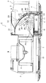
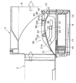
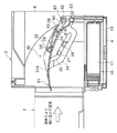
図1に示す浴室用の換気装置1は、浴室(図示せず)の天井T内に取り付ける本体ケース2を有している。この本体ケース2の下面には、浴室内(図示せず)の空気を吸気する吸気口3と浴室内へ風を吹き出す吹出口4とが設けられている。吹出口4内にはヒータユニット10が取り付けられており、吹出口4から吹き出す空気をそのヒータユニット10のPTCヒータ(自己温度制御機能付きヒータ)11によって暖めるようになっている。ヒータであるPTCヒータ11は暖房モードや乾燥モードのときに通電される。
【0019】
本体ケース2の側方には排気口6が設けられており、この排気口6は接続ダクト7およびこの接続ダクト7に接続された排気ダクト8を介して室外に連通されている。本体ケース2内には、吸気口3から空気を吸い込んで吹出口4や排気口6へ送風するシロッコファン(送風手段)9が設けられている。Mはシロッコファン9を回転させるモータであり、12は吸気口3に設けられた吸気グリル、13は吹出口4に設けられた吹出グリルである。
【0020】
また、本体ケース2内にはダンパー20が設けられており、このダンパー20は実線位置(第2位置)と鎖線位置(第1位置)とに切り換え可能となっている。そして、暖房モードや乾燥モードのときダンパー20が実線位置に切り換わって吸気口3と吹出口4とが連通される。また、換気モードのときダンパー20が鎖線位置に切り換わって吸気口3と排気口6とが連通される。
【0021】
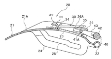
ダンパー20は、図2および図3に示すように、平面視がほぼ長方形を呈しているとともに上側が凸に緩やかに湾曲したダンパー板21と、このダンパー板21の後部(図2において下部)に形成された軸22とを有している。この軸22の両端部22A,22Aが本体ケース2の側壁部に回動自在に軸支され、ダンパー20は軸22回りに回動するようになっている。
【0022】
ダンパー20の下面にはリブ24が形成され、このリブ24にはダンパー20の前後方向に沿って延びたガイド孔25が形成されている。このガイド孔25にはカム26(図1参照)に設けた突起27が挿入されており、カム26は図示しない電動室に設けたダンパー用モータ(図示せず)によって軸28回り(時計回り)に回転していくようになっている。そして、このカム26の回転によってダンパー20が軸22回りに回動する。
【0023】
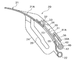
また、ダンパー板21には開口23が形成され、この開口23を開閉するサブダンパー30がダンパー板21の裏面(図3において上面)21Aに取り付けられている。サブダンパー30は、開口23を閉塞する板部31と、この板部31の上部(図2において)に設けられた一対の軸部32,32とを有している。そして、開口23とサブダンパー30とでシロッコファン9から送風される空気の一部を排気口6へ送り出すことが可能な送出手段が構成される。
【0024】
軸部32,32の端部はダンパー板21の裏面21Aに設けた一対の軸受部33,33に回動自在に軸支され、サブダンパー30は軸部32,32回りに回動するようになっている。そして、サブダンパー30は一方の軸部32に設けた捻れコイル(付勢部材)34により開口23を閉塞(閉成)する方向(図3において時計回り)に付勢されている。捻れコイル34の付勢力は小さく設定され、サブダンパー30はシロッコファン9から送風される空気の風圧によって捻れコイル34の付勢力に抗して回動できるようになっている。
【0025】
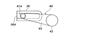
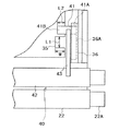
また、サブダンパー30の板部31の両側部には凹部35,35が形成され、この凹部35,35に対向するようにガイド部材36,36がダンパー板21の裏面21Aに設けられている。各ガイド部材36の内側面には図4に示すように左右方向に延びたガイド溝36Aが形成されている。このガイド溝36Aには、後述するロック部材40のピン41の一端部41Aが挿入され、ピン41はガイド溝36Aに沿って移動可能となっている。
【0026】
ロック部材40は、本体ケース2の側壁部に回動自在に軸支されるとともにダンパー20の軸22の上方に位置する軸部42と、この軸部42から上方(図2において)に延びた一対のアーム43,43とを有し、アーム43,43の先端部には左右方向(図2において)に延びたピン41,41が設けられている。このピン41,41の他端部41B,41Bがサブダンパー30の板部31の裏面31Aに当接してサブダンパー30の板部31を押さえている。この押さえによりサブダンパー30は図3に示す位置に固定(ロック)され、このサブダンパー30によりダンパー20の開口23が閉塞されている。
【0027】
各ピン41の太さは、図5に示すように、サブダンパー30の凹部35の長さL1より小さく設定され、またサブダンパー30の板部31の裏面31Aに当接しているピン41の他端部41Bの長さL2は凹部35の幅Wより小さく設定されている。
【0028】
そして、ダンパー20が軸22回りに回動すると、ガイド部材36のガイド溝36Aにアーム43のピン41の一端部41Aが挿入されていることにより、ロック部材40はその回動とともに軸部42回りに回動していく。ロック部材40の回動支点とダンパー20の回動支点とがずれていることにより、ダンパー20が軸22を中心にして図3の位置から反時計回りに回動していくと、この回動とともにロック部材40のピン41がガイド部材36のガイド溝36Aに沿ってガイド溝36Aの下端側(図3において)に移動していく。そして、ダンパー20が所定角度回動すると、ロック部材40のピン41がサブダンパー30の凹部35の位置に位置し、そのピン41によるサブダンパー30の板部31の押さえが解除されるようになっている。
【0029】
すなわち、ロック部材40によるサブダンパー30の固定は解除され、サブダンパー30は、捻れコイル34の付勢力に抗して軸部32,32回りに回動可能となる。そして、捻れコイル34とロック部材40とでサブダンパー30を開閉する開閉手段が構成される。
【0030】
[動 作]
次に、上記のように構成される換気装置1の動作について説明する。
【0031】
換気装置1が停止されているとき、ダンパー20は実線位置に位置され、サブダンパー30はロック部材40のピン41により図3に示す位置に固定され、ダンパー20の開口23はサブダンパー30により閉塞されている。
【0032】
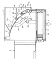
いま、図示しない操作部の操作により乾燥モードが設定されると、ダンパー用モータが駆動されてカム26が軸28を中心にして時計回りに回転し、このカム26の回転によってダンパー20が軸22を中心にして反時計回りに回動していく。そして、ダンパー20が図1に示す鎖線位置、すなわち図6に示す位置まで回動する。
【0033】
そして、さらにダンパー用モータの駆動によりカム26が軸28を中心にして時計回りに回転していくと、ダンパー20が図6に示す位置から時計回りに回動していくとともに、モータMが駆動されてシロッコファン9が回転され、シロッコファン9の回転により浴室の空気が吸気口3へ吸い込まれて矢印方向へ送風されていく。また、ヒータユニット10のPTCヒータ11が通電される。
【0034】
ダンパー20が図7および図8に示す位置に到達すると、ロック部材40のピン41がサブダンパー30の凹部35の位置に位置し、そのピン41によるサブダンパー30の板部31の押さえ、すなわちサブダンパー30の固定が解除される。
【0035】
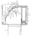
一方、シロッコファン9の回転により矢印方向へ空気が送風されているので、サブダンパー30は風圧によって捻れコイル34の付勢力に抗して軸部32,32を中心にして反時計回りに回動し、この回動の際ロック部材40のピン41,41の他端部41B,41Bがサブダンパー30の凹部35,35内を通過していき、そして図9および図10に示すように、サブダンパー30の先端部がロック部材40の上側に移動する。これにより、ダンパー20の開口23は開成される。この状態で、ダンパー20はさらに時計回りに回動していき、図11に示す位置に停止される。
【0036】
シロッコファン9から送風される浴室の空気は、ダンパー20によって吹出口4へ案内されて、その吹出口4から浴室へ吹き出していく。この吹出口4から吹き出す空気はPTCヒータ11によって暖められていき、浴室が暖められていくことになる。
【0037】
他方、シロッコファン9から送風される浴室の空気の一部は、ダンパー20の開口23から排気口6,接続ダクト7および排気ダクト8を介して室外に排気されていく。この排気により浴室の湿気が室外に排気されるので、浴室は効率よく乾燥していき、浴室に例えば洗濯物を干しておけばその洗濯物を短時間で乾燥させることができる。
【0038】
この乾燥モードから暖房モードに切り換わると、モータMの駆動が停止されてシロッコファン9の回転が停止される。このシロッコファン9の回転の停止により矢印方向の送風が停止するので、サブダンパー30は捻れコイル34の付勢力により軸32を中心にして時計回りに回動して、サブダンパー30の両側縁部が図12に示すようにロック部材40のピン41,41に係合する。
【0039】
そして、上記と同様にしてダンパー用モータが駆動されてダンパー20が軸22を中心にして反時計回りに回動していき、ダンパー20が図9に示す位置に到達すると、ロック部材40のピン41,41がサブダンパー30の凹部35,35の位置に位置する。サブダンパー30は捻れコイル34によって軸22を中心に時計回りに付勢されていることにより、サブダンパー30は軸22を中心に時計回りに回動していくとともに、ロック部材40のピン41,41の他端部41B,41Bがサブダンパー30の凹部35,35内を通過していく。そして、サブダンパー30は、図7および図8に示すように、ロック部材40のピン41,41の下側位置へ移動し、ダンパー20の開口23がサブダンパー30により閉塞される。
【0040】
この状態で、さらにダンパー20が反時計回りに回動していくと、サブダンパー30の板部31の裏面(図7および図8において上面)31Aにロック部材40のピン41,41が当接して、サブダンパー30がそのピン41,41によってダンパー20に固定される。換言すれば、サブダンパー30はロック部材40によりダンパー20に固定され、開口23の閉塞が固定されることになる。そして、ダンパー20が図6に示す位置へ移動されると、ダンパー20は時計回りに回動されて図1の実線位置へ停止される。
【0041】
ダンパー20が図1の実線位置に停止されると、モータMが駆動されてシロッコファン9が回転していき、浴室の空気が吸気口3へ吸い込まれていく。この吸い込まれた空気は矢印方向へ送風され、この送風される空気はダンパー20によって吹出口4へ案内されて、その吹出口4から浴室へ吹き出していく。この吹出口4から吹き出す空気はPTCヒータ11によって暖められていき、浴室の暖房が行われることになる。
【0042】
この際、サブダンパー30はロック部材40によりダンパー20に固定されているので、風圧によって開成してしまうことはない。
【0043】
暖房モードから換気モードに切り換わると、モータMの駆動が停止されてシロッコファン9の回転が停止されるとともにPTCヒータ11の通電が停止される。そして、ダンパー用モータが駆動されてダンパー20が図6に示す位置まで回動される。ダンパー20が図6に示す位置まで回動すると、ダンパー用モータの駆動が停止されるとともにモータMが駆動されてシロッコファン9が回転していき、浴室の空気が吸気口3へ吸い込まれていく。この吸い込まれた空気は矢印方向へ送風され、この送風される空気は排気口6,接続ダクト7および排気ダクト8(図1参照)を介して室外に排気されていき、浴室の換気が行われる。
【0044】
換気モードから暖房モードに切り換わると、シロッコファン9の回転が停止されてダンパー用モータが駆動される。このダンパー用モータの駆動により、ダンパー20は図6に示す位置から図1の実線位置まで回動される。この回動の途中で、ダンパー20は図7および図8に示す位置を通過するが、シロッコファン9の回転が停止されているとともに捻れコイル34の付勢力により、サブダンパー30はダンパー20の開口23を閉成したままである。
【0045】
ダンパー20が図1の鎖線位置に到達すると、ダンパー用モータの駆動が停止され、モータMが駆動されるととももにPTCヒータ11が通電される。そして、上記と同様にして浴室の暖房が行われる。
【0046】
また、換気モードから乾燥モードに切り換わった場合には、シロッコファン9の回転が停止されずに、ダンパー20が図6に示す位置から図11に示す位置へ回動される。そして、その回動の途中でダンパー20が図7および図8に示す位置に到達した際に、上記と同様にしてサブダンパー30が開成する。
【0047】
このように、サブダンパー30の開成に専用のモータを必要としないので、換気装置1の小型軽量化を図ることができる。
【0048】
また、乾燥モードの際、ダンパー20を排気口6を閉塞する位置に停止させてサブダンパー30を開成させているので、排気口6から排気される排気風量や吹出口4から吹き出す循環風量は、ダンパー20の開口23の大きさで決定されることになる。このため、製品毎による排気風量や循環風量のバラツキを小さくすることができる。さらに、ダンパー20は第1位置と第2位置との中間位置に停止されないので、ダンパー20の先端で発生する風切り音やダンパー20の振動によるバタツキ音が発生せず、このため、乾燥モードの運転中であっても静かなものとなる。
[第2実施形態]
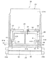
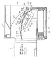
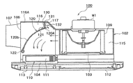
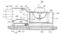
図13は第2実施形態の換気装置100を示したものであり、この換気装置100は、第1実施形態と同様に図示しない浴室の天井内(図示せず)に取り付ける本体ケース102を有している。この本体ケース102の下面には、浴室内(図示せず)の空気を吸気する吸気口103と浴室内へ風を吹き出す吹出口104とが設けられている。吹出口104内にはヒータユニット110が取り付けられており、吹出口104から吹き出す空気をそのヒータユニット110のPTCヒータ(ヒータ)111によって暖めるようになっている。PTCヒータ111は暖房モードや乾燥モードのときに通電される。
【0049】
本体ケース102の側方には排気口106が設けられており、この排気口106は接続ダクト107に接続された図示しない排気ダクトを介して室外に連通されている。本体ケース102は、シロッコファン(送風手段)109を収納したシロッコファン室115と、ダンパー120を収納したダンパー室116とを有している。シロッコファン109は回転して吸気口103から空気を吸い込み、この吸い込んだ空気を吹出口104や排気口106へ送風するようになっている。M1はシロッコファン109を回転させるモータであり、112は吸気口103に設けられた吸気グリル、113は吹出口104に設けられた吹出グリルである。
【0050】
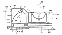
ダンパー120は図13に示す位置(第2位置)と図14に示す位置(第1位置)とに切り換え可能となっている。ダンパー120の切り換えは図示しないモータによって行われる。そして、暖房モードや乾燥モードのときダンパー120が図13の実線位置に切り換わって吸気口103と吹出口104とが連通され、換気モードのときダンパー120が図14に示す実線位置に切り換わって吸気口113と排気口106とが連通される。
【0051】
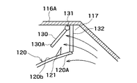
ダンパー室116の天板116Aと、図13の実線位置にあるダンパー120の先端部120Aとの間は、所定の大きさの間隙117が形成されており、この間隙117がシロッコファン109から送風される空気の一部を排気口106へ案内するバイパス風路となっている。
【0052】
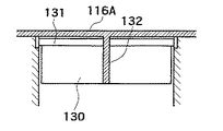
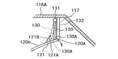
バイパス風路117には、図15および図16に示すように、そのバイパス風路117を開閉するシャッター130が配置されており、このシャッター130の上部には軸部131が設けられている。この軸部131の両端部がダンパー室116の側壁部に回動自在に軸支され、シャッター130は軸部131回りに回動することによりバイパス風路117を開閉する。また、バイパス風路117にはストッパ132が設けられており、このストッパ132によりシャッター130が図13の位置から反時計回りに回動しないようになっている。そして、バイパス風路117とシャッター130とでシロッコファン109から送風される空気の一部を排気口106へ送り出すことが可能な送出手段を構成する。
【0053】
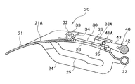
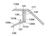
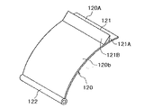
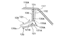
また、図17に示すようにダンパー120の先端部の近傍の上面120bには幅方向に延びる突条部(係止爪)121が形成されており、この突条部121の前面121Aがその上面120bから起立した平面状の当接面となっている。また、突条部121の後面121Bは、ダンパー120が図20に示す位置に位置しているとき、風路損が小さくなるように傾斜面となっている。ダンパー120の後部には図17に示すように軸部122が形成され、この軸部122がダンパー室116の側壁に回動自在に軸支され、ダンパー120は軸部122回りに回動するようになっている。
【0054】
そして、シャッター130が図18に示す破線位置へ回動した際にシャッター130の下端部130Aがその突条部121の当接面121Aに当接してバイパス風路117を閉成するようになっている。また、シャッター130が図13および図16の実線位置に位置しているとき、ダンパー120が軸部122を中心にして時計回りに回動できるように、すなわち、ダンパー120が図19に示す破線位置から実線位置へ回動する際に突条部121がシャッター130に当接しないように突条部121の高さや位置が設定されている。
[動 作]
次に、第2実施形態の換気装置100の動作について説明する。
【0055】
換気装置100が停止されているとき、ダンパー120は図13に示す位置(第2位置)に位置され、ダンパー室116のバイパス風路117がシャッター130により閉成されている。
【0056】
そして、図示しない操作部の操作により乾燥モードが設定されると、ダンパー用のモータが駆動されてダンパー120が図13に示す位置から図20に示す位置(第1位置)へ切り換えられる。ダンパー120が第1位置へ切り換えられると、ダンパー用のモータの駆動が停止されるとともにモータM1が駆動されてシロッコファン109が回転され、シロッコファン109の回転により浴室の空気が吸気口103へ吸い込まれて矢印方向へ送風される。
【0057】
この送風の風圧によってシャッター130は軸部131を中心にして時計回りに回動し、バイパス風路117が開成される。そして、再度ダンパー用のモータが駆動されてダンパー120が図20に示す位置から図21に示す第2位置へ切り換えられるとともに、ヒータユニット110のPTCヒータ111が通電される。
【0058】
ダンパー120が図21に示す第2位置へ切り換えられた際、ダンパー120の先端部120Aはストッパ132の下部に当接してダンパー120は所定位置(第2位置)に確実に切り換えられることになる。
【0059】
ところで、シャッター130は風圧によって図21および図22に示す位置に回動されているので、ダンパー120が第2位置に切り換えられてもシャッター130はバイパス風路117を開成したままである。
【0060】
そして、ダンパー120が第2位置に位置していることにより、シロッコファン109によって矢印方向へ送風される空気はダンパー120によって吹出口104へ案内されて、その吹出口104から浴室へ吹き出していく。この吹出口104から吹き出す空気はPTCヒータ111によって暖められていき、浴室の暖房が行われることになる。
【0061】
また、シャッター130はバイパス風路117を開成しているので、シロッコファン109から送風される浴室の空気の一部は、バイパス風路117を通って排気口106および接続ダクト107に接続された排気ダクトを介して室外に排気されていく。この排気により浴室の湿気が室外に排気されるので、浴室は効率よく乾燥していき、浴室に例えば洗濯物を干しておけばその洗濯物を短時間で乾燥させることができる。
【0062】
この乾燥モードから暖房モードに切り換わると、モータM1の駆動が停止されてシロッコファン9の回転が停止される。このシロッコファン9の回転の停止によりシャッター130は自重により図14に示す位置に位置し、バイパス風路117を閉塞する位置に位置することになる。
【0063】
そして、ダンパー用のモータが駆動されてダンパー120が図14に示す第1位置に切り換えられる。この後、ダンパー120が図14に示す第1位置から図13に示す第2位置へ切り換えられる。この際、シャッター130はバイパス風路117を閉塞する位置に位置しているので、図16に示すように、ダンパー120の突条部131はシャッター130の下端部(先端部)130Aの左側に位置することになる。
【0064】
ダンパー120が第2位置に切り換わると、モータM1が駆動されてシロッコファン109が回転され、シロッコファン109の回転により浴室の空気が吸気口103へ吸い込まれて矢印方向へ送風されていく。この送風される空気はダンパー120によって吹出口104へ案内されて、その吹出口104から浴室へ吹き出していく。この吹出口104から吹き出す空気はPTCヒータ111によって暖められていき、浴室の暖房が行われることになる。
【0065】
また、シロッコファン109の回転による送風の風圧によってシャッター130は軸部131を中心にして時計回りに回動して、図18の破線で示すように、シャッター130の下端部130Aがダンパー120の突条部121の前面である当接面121Aに当接してバイパス風路117を閉成するので、シロッコファン109から送風される空気の一部がバイパス風路117を通って排気口106へ流れてしまうことはなく、このため浴室の暖房を効率よく行うことができる。
【0066】
乾燥モードや暖房モードから換気モードに切り換わると、PTCヒータ111の通電が停止されるとともにダンパー用のモータが駆動される。このダンパー用のモータの駆動によりダンパー120が図13または図21に示す第2位置から図20に示す第1位置に切り換えられる。ダンパー120が第1位置に切り換えられると、シロッコファン109によって送風される空気は排気口106および接続ダクト107に接続された排気ダクト(図示せず)を介して室外に排気されていき、浴室の換気が行われる。
【0067】
この換気モードから乾燥モードや暖房モードに切り換わると、PTCヒータ111が通電されるとともにダンパー用のモータが駆動されて、ダンパー120が図20の第1位置から図13に示す第2位置へ切り換えられることにより行われる。この場合、乾燥モードのときにはモータM1は駆動されたままダンパー120が第2位置へ切り換えることによりシャッター130は開成され、暖房モードのときにはモータM1の駆動は停止されてダンパー120が第2位置へ切り換えられることによりシャッター130は閉成する。
【0068】
このように、シャッター130の開成に専用のモータを必要としないので、換気装置100の小型軽量化を図ることができる。
【0069】
また、乾燥モードの際、ダンパー120を排気口106を閉塞する第2位置に停止させてシャッター130を開成させているので、排気口106から排気される排気風量や吹出口104から吹き出す循環風量は、バイパス風路117の断面積で決定されることになる。このため、製品毎による排気風量や循環風量のバラツキを小さくすることができる。さらに、ダンパー120が第1位置と第2位置との中間位置に停止しないので、ダンパー120の先端で発生する風切り音やダンパー120の振動によるバタツキ音が発生せず、このため、乾燥モードの運転中であっても静かなものとなる。
【0070】
第1,第2実施形態のいずれも換気装置1,100は浴室用のものについて説明したが、かならずしも浴室用である必要はなく、浴室以外の部屋を換気する換気装置であってもよい。
【0071】
【発明の効果】
以上説明したように、この発明によれば、短時間で衣類等の乾燥を行うことができるとともに製品毎による排気風量や循環風量のバラツキを小さくすることができるとともに、ダンパーのバタツキ音を抑制することができる。
【図面の簡単な説明】
【図1】この発明に係る浴室用の換気装置の構成を示した断面図である。
【図2】図1に示す換気装置のダンパーを示した平面図である。
【図3】図2に示すダンパーの構成を示した断面図である。
【図4】ガイド部材とロック部材との関係を示した説明図である。
【図5】図2に示すダンパーの一部を拡大した部分拡大図である。
【図6】ダンパーが第1位置に位置している状態を示した説明図である。
【図7】ダンパーが所定角度へ回動した状態を示した説明図である。
【図8】ダンパーが所定角度へ回動した際のサブダンパーとロック部材との位置関係を示した説明図である。
【図9】ロック部材によるサブダンパーのロックが解除された状態を示した説明図である。
【図10】サブダンパーのロックが解除された際のサブダンパーとロック部材との位置関係を示した説明図である。
【図11】サブダンパーのロックが解除されたダンパーが第2位置へ移動した状態を示した説明図である。
【図12】シロッコファンの回転が停止した際のサブダンパーの状態を示した説明図である。
【図13】第2実施形態の換気装置の構成を示した断面図である。
【図14】図12の換気装置のダンパーが第1位置に切り換わった状態を示した断面図である。
【図15】ストッパとシャッターとを示した説明図である。
【図16】シャッターとダンパーの位置関係を示した説明図である。
【図17】ダンパーを示した斜視図である。
【図18】図16に示すシャッターが回動してパイパス風路が閉成されることを示した説明図である。
【図19】ダンパーが回動できることを示す説明図である。
【図20】ダンパーが第1位置へ切り換えられてシロッコファンが回転された状態を示した説明図である。
【図21】シロッコファンを回転したままダンパーを第2位置へ切り換えた状態を示した説明図である。
【図22】シャッターが開成している状態を示した説明図である。
【符号の説明】
3 吸気口
4 吹出口
6 排気口
9 シロッコファン(送風手段)
11 ヒータ(PTCヒータ)
20 ダンパー
23 開口
30 サブダンパー[0001]
TECHNICAL FIELD OF THE INVENTION
The present invention relates to a ventilator for ventilating a room such as a bathroom.
[0002]
[Prior art]
Conventionally, an intake port that inhales air in a bathroom, an exhaust port that exhausts the inhaled air to the outside, an air outlet that returns the intake air to the bathroom, and a blower that inhales air from the intake port and blows the air. There is known a ventilator for a bathroom including a damper for switching a blowing direction of air blown from the blower to the exhaust port or the outlet, and a heater for heating air blown from the outlet (Patent Document 1). 1).
[0003]
Such a ventilator ventilates the bathroom by positioning the damper at the first position in the ventilation mode, closing the outlet, and exhausting the air taken in from the inlet through the outlet. Further, in the heating mode, the damper is located at the second position, the exhaust port is closed, and the air taken in from the intake port is heated by the heater, and the heated air is blown out from the outlet to heat the bathroom. is there.
[0004]
By the way, if you want to dry your laundry in the bathroom and dry it, you can put the ventilation system in the heating mode.However, in this heating mode, the air in the bathroom is only heated and circulated by the heater. Therefore, the clothes cannot be dried efficiently.
[0005]
Therefore, a device has been proposed in which the humidity in the bathroom is removed by alternately repeating the heating mode and the drying mode.
[0006]
In addition, the damper is located at an intermediate position between the first position and the second position, and while the bathroom is being heated, a part of the air taken in from the intake port is exhausted from the exhaust port to discharge moisture from the bathroom to the outside. There is a ventilator that removes moisture from the bathroom.
[0007]
[Patent Document 1]
JP-A-9-126516 (page 3, FIG. 1)
[0008]
[Problems to be solved by the invention]
However, in the former case, since the air heated in the heating mode is exhausted in the ventilation mode, the bathroom cannot be warmed in the ventilation mode, and it takes a long time to dry the clothes. . In addition, there is a problem that the heating efficiency is very poor due to exhausting the heated air. Furthermore, since moisture cannot be removed in the heating mode, dew condensation may occur.
[0009]
In the latter case, the amount of exhaust air exhausted from the exhaust port and the amount of circulation air circulated are determined by the intermediate position of the damper. mm (= A). Furthermore, the tip position of the damper is shifted by several mm (= B) due to the proximity sensor that detects the position of the damper, and a total error of about ± (A + B) mm occurs from the set position. For this reason, the exhaust air volume and the circulating air volume vary greatly for each product, and the time required for drying greatly differs for each product. Further, since the damper is stopped at the intermediate position, the position of the damper is not stabilized, and the wind blown from the blower causes the damper to vibrate at the intermediate position, thereby causing a rattling sound.
[0010]
An object of the present invention is to provide a ventilation device that can dry clothes and the like in a short time, can reduce variations in exhaust air volume and circulation air volume for each product, and does not generate rattling noise. is there.
[0011]
[Means for Solving the Problems]
In order to achieve the above object, the invention according to
When the damper is switched to the second position, there is provided a sending means capable of sending a part of the air blown from the blowing means to the exhaust port.
[0012]
When a drying mode for drying the room is set, the heater is turned on and the sub damper is opened.
[0013]
According to a second aspect of the present invention, the sending means includes an opening provided in the damper, a sub damper for opening and closing the opening, and an opening and closing means for opening and closing the sub damper.
The opening / closing means opens and closes the sub damper by performing an on / off operation of the blowing means and a switching operation of the damper in a preset order.
[0014]
According to a third aspect of the present invention, the opening / closing means includes an urging member for urging the sub-damper in a closing direction, the sub-damper being fixed at a closed position, and the damper being in a first position and a second position. A lock member for releasing the fixation of the sub-damper only when it comes to a predetermined position between
The sub damper is opened against the urging force of the urging member by the wind pressure of the blower when the fixation by the lock member is released,
The opened sub damper is closed by the urging member when the blowing means stops, and locks the closed sub damper when the damper moves from a predetermined position to the first position or the second position. The member is fixed.
[0015]
Further, the sending means includes a bypass air passage that guides a part of the air blown from the blowing device to the exhaust port when the damper is located at the second position, and a shutter that opens and closes the bypass air passage. It is characterized by having.
[0016]
According to a fourth aspect of the present invention, the delivery unit includes a bypass air passage that guides a part of the air blown from the blower unit to the exhaust port when the damper is located at the second position; And a shutter for opening and closing the shutter,
The shutter is opened by wind pressure by the blowing of the blowing means,
The opening and closing means has a locking claw provided on the damper and for maintaining the shutter closed,
When the blower is operated after the damper moves from the first position to the second position when the shutter is closed, the locking claw is locked to the shutter to maintain the shutter closed. Let
When the shutter is opened by the wind pressure and the damper moves from the first position to the second position, the opening of the shutter is maintained without the locking claw being locked to the shutter. .
[0017]
Further, the opening and closing means opens and closes the shutter by performing an on / off operation of the air blowing means and a switching operation of a damper in a preset order.
[0018]
BEST MODE FOR CARRYING OUT THE INVENTION
An embodiment of a ventilation device according to the present invention will be described below with reference to the drawings.
[First Embodiment]
A
[0019]
An
[0020]
Further, a
[0021]
As shown in FIGS. 2 and 3, the
[0022]
A
[0023]
An
[0024]
The ends of the
[0025]
Further,
[0026]
The
[0027]
As shown in FIG. 5, the thickness of each
[0028]
When the
[0029]
That is, the fixing of the
[0030]
[motion]
Next, the operation of the
[0031]
When the
[0032]
When the drying mode is set by operating an operation unit (not shown), the motor for the damper is driven to rotate the
[0033]
When the
[0034]
When the
[0035]
On the other hand, since the air is blown in the direction of the arrow by the rotation of the sirocco fan 9, the
[0036]
The air in the bathroom blown from the sirocco fan 9 is guided to the
[0037]
On the other hand, a part of the bathroom air blown from the sirocco fan 9 is exhausted from the
[0038]
When the mode is switched from the drying mode to the heating mode, the driving of the motor M is stopped, and the rotation of the sirocco fan 9 is stopped. When the rotation of the sirocco fan 9 stops, the blowing in the direction of the arrow stops, so that the sub-damper 30 rotates clockwise about the
[0039]
Then, the damper motor is driven in the same manner as described above, and the
[0040]
In this state, when the
[0041]
When the
[0042]
At this time, since the
[0043]
When the mode is switched from the heating mode to the ventilation mode, the drive of the motor M is stopped, the rotation of the sirocco fan 9 is stopped, and the energization of the
[0044]
When the mode is switched from the ventilation mode to the heating mode, the rotation of the sirocco fan 9 is stopped and the damper motor is driven. By driving the damper motor, the
[0045]
When the
[0046]
Further, when the mode is switched from the ventilation mode to the drying mode, the rotation of the sirocco fan 9 is not stopped, and the
[0047]
As described above, since a dedicated motor is not required to open the
[0048]
Further, in the drying mode, the
[Second embodiment]
FIG. 13 shows a
[0049]
An
[0050]
The
[0051]
A
[0052]
As shown in FIGS. 15 and 16, a
[0053]
Further, as shown in FIG. 17, a ridge (locking claw) 121 extending in the width direction is formed on the
[0054]
When the
[motion]
Next, the operation of the
[0055]
When the
[0056]
When the drying mode is set by operating an operation unit (not shown), the damper motor is driven, and the
[0057]
The
[0058]
When the
[0059]
By the way, since the
[0060]
When the
[0061]
Further, since the
[0062]
When the mode is switched from the drying mode to the heating mode, the driving of the motor M1 is stopped, and the rotation of the sirocco fan 9 is stopped. When the rotation of the sirocco fan 9 stops, the
[0063]
Then, the damper motor is driven, and the
[0064]
When the
[0065]
Further, the
[0066]
When the mode is switched from the drying mode or the heating mode to the ventilation mode, the power supply to the
[0067]
When the mode is switched from the ventilation mode to the drying mode or the heating mode, the
[0068]
As described above, since a dedicated motor is not required to open the
[0069]
In the drying mode, since the
[0070]
In both the first and second embodiments, the
[0071]
【The invention's effect】
As described above, according to the present invention, it is possible to dry clothes and the like in a short time, to reduce variations in exhaust air volume and circulating air volume for each product, and to suppress flapping noise of a damper. be able to.
[Brief description of the drawings]
FIG. 1 is a cross-sectional view showing a configuration of a bathroom ventilator according to the present invention.
FIG. 2 is a plan view showing a damper of the ventilation device shown in FIG.
FIG. 3 is a cross-sectional view illustrating a configuration of a damper illustrated in FIG. 2;
FIG. 4 is an explanatory diagram showing a relationship between a guide member and a lock member.
FIG. 5 is a partially enlarged view in which a part of the damper shown in FIG. 2 is enlarged.
FIG. 6 is an explanatory diagram showing a state where the damper is located at a first position.
FIG. 7 is an explanatory diagram showing a state in which the damper has rotated to a predetermined angle.
FIG. 8 is an explanatory diagram showing a positional relationship between a sub-damper and a lock member when the damper rotates to a predetermined angle.
FIG. 9 is an explanatory view showing a state in which the sub damper is unlocked by the lock member.
FIG. 10 is an explanatory diagram showing a positional relationship between the sub damper and the lock member when the lock of the sub damper is released.
FIG. 11 is an explanatory diagram showing a state in which the damper in which the sub-damper is unlocked has moved to the second position.
FIG. 12 is an explanatory diagram showing a state of a sub damper when rotation of a sirocco fan is stopped.
FIG. 13 is a cross-sectional view illustrating a configuration of a ventilation device according to a second embodiment.
FIG. 14 is a cross-sectional view showing a state where a damper of the ventilator of FIG. 12 is switched to a first position.
FIG. 15 is an explanatory diagram showing a stopper and a shutter.
FIG. 16 is an explanatory diagram showing a positional relationship between a shutter and a damper.
FIG. 17 is a perspective view showing a damper.
FIG. 18 is an explanatory view showing that the shutter shown in FIG. 16 is rotated to close the bypass air path.
FIG. 19 is an explanatory view showing that the damper can rotate.
FIG. 20 is an explanatory diagram showing a state in which the damper is switched to the first position and the sirocco fan is rotated.
FIG. 21 is an explanatory diagram showing a state in which the damper is switched to the second position while the sirocco fan is rotating.
FIG. 22 is an explanatory diagram showing a state where a shutter is opened.
[Explanation of symbols]
3 Inlet
4 outlet
6 Exhaust port
9. Sirocco fan (blowing means)
11 heater (PTC heater)
20 Damper
23 opening
30 sub damper
Claims (4)
前記ダンパーが第2位置に切り換わっているとき、前記送風手段から送風される空気の一部を前記排気口へ送り出すことが可能な送出手段を設けたことを特徴とする換気装置。An intake port for inhaling air in the room, an exhaust port for exhausting the inhaled air to the outside, an air outlet for returning the inhaled air to the room, and blowing means for sucking air from the intake port to blow air. A ventilator including a damper that switches between a first position for guiding air blown from a blowing unit to the exhaust port and a second position for guiding the air to the outlet, and a heater that heats air blown from the outlet. And
A ventilating device provided with a sending means capable of sending a part of the air blown from the blowing means to the exhaust port when the damper is switched to the second position.
この開閉手段は、予め設定した順序で前記送風手段のオン・オフ動作とダンパーの切換動作とを行うことによってサブダンパーを開閉することを特徴とする請求項1に記載の換気装置。The sending means includes an opening provided in the damper, a sub-damper for opening and closing the opening, and opening and closing means for opening and closing the sub-damper,
The ventilator according to claim 1, wherein the opening / closing unit opens and closes the sub damper by performing an on / off operation of the blowing unit and a switching operation of the damper in a preset order.
前記サブダンパーは、ロック部材による固定が解除された際に前記送風手段の風圧によって前記付勢部材の付勢力に抗して開成し、
この開成したサブダンパーは、前記送風手段が停止した際に前記付勢部材により閉成し、前記ダンパーが所定位置から第1位置または第2位置へ移動するとき、閉成したサブダンパーを前記ロック部材が固定することを特徴とする請求項2に記載の換気装置。The opening / closing means includes an urging member for urging the sub-damper in a closing direction, and fixing the sub-damper at a closed position and the damper at a predetermined position between the first position and the second position. Only when the sub damper is unlocked.
The sub damper is opened against the urging force of the urging member by the wind pressure of the blower when the fixation by the lock member is released,
The opened sub damper is closed by the urging member when the blowing means stops, and locks the closed sub damper when the damper moves from a predetermined position to the first position or the second position. The ventilation device according to claim 2, wherein the member is fixed.
前記シャッターは前記送風手段の送風による風圧によって開成し、
前記開閉手段は、前記ダンパーに設けられるとともに前記シャッターの閉成を維持するための係止爪を有し、
前記シャッターが閉成している際、前記ダンパーが第1位置から第2位置へ移動した後に前記送風手段が動作したとき、前記係止爪がシャッターに係止してこのシャッターの閉成を維持させ、
前記シャッターが前記風圧によって開成している際、前記ダンパーが第1位置から第2位置へ移動したとき、前記係止爪がシャッターに係止せずにシャッターの開成が維持されることを特徴とする請求項1に記載の換気装置。The sending means includes a bypass air passage that guides a part of the air blown from the blowing device to the exhaust port when the damper is located at the second position, a shutter that opens and closes the bypass air passage, Opening and closing means for opening and closing the shutter,
The shutter is opened by wind pressure by the blowing of the blowing means,
The opening and closing means has a locking claw provided on the damper and for maintaining the shutter closed,
When the blower is operated after the damper moves from the first position to the second position when the shutter is closed, the locking claw is locked to the shutter to maintain the shutter closed. Let
When the shutter is opened by the wind pressure and the damper moves from the first position to the second position, the opening of the shutter is maintained without the locking claw being locked to the shutter. The ventilation device according to claim 1.
Priority Applications (1)
| Application Number | Priority Date | Filing Date | Title |
|---|---|---|---|
| JP2003134334A JP4023376B2 (en) | 2003-05-13 | 2003-05-13 | Ventilation equipment |
Applications Claiming Priority (1)
| Application Number | Priority Date | Filing Date | Title |
|---|---|---|---|
| JP2003134334A JP4023376B2 (en) | 2003-05-13 | 2003-05-13 | Ventilation equipment |
Publications (2)
| Publication Number | Publication Date |
|---|---|
| JP2004340407A true JP2004340407A (en) | 2004-12-02 |
| JP4023376B2 JP4023376B2 (en) | 2007-12-19 |
Family
ID=33524927
Family Applications (1)
| Application Number | Title | Priority Date | Filing Date |
|---|---|---|---|
| JP2003134334A Expired - Fee Related JP4023376B2 (en) | 2003-05-13 | 2003-05-13 | Ventilation equipment |
Country Status (1)
| Country | Link |
|---|---|
| JP (1) | JP4023376B2 (en) |
Cited By (12)
| Publication number | Priority date | Publication date | Assignee | Title |
|---|---|---|---|---|
| KR100733412B1 (en) * | 2006-06-23 | 2007-06-29 | 허만영 | Cooking hot hood with drying function |
| JP2007205642A (en) * | 2006-02-02 | 2007-08-16 | Max Co Ltd | Blower |
| JP2007205641A (en) * | 2006-02-02 | 2007-08-16 | Max Co Ltd | Blower |
| JP2007225183A (en) * | 2006-02-23 | 2007-09-06 | Max Co Ltd | Blowing device |
| JP2007247957A (en) * | 2006-03-15 | 2007-09-27 | Max Co Ltd | Air blowing device |
| JP2007285237A (en) * | 2006-04-18 | 2007-11-01 | Max Co Ltd | Rotary fan and blower device |
| JP2008020149A (en) * | 2006-07-14 | 2008-01-31 | Max Co Ltd | Air blower |
| CN107860063A (en) * | 2017-11-02 | 2018-03-30 | 珠海格力电器股份有限公司 | Indoor unit and air conditioner with same |
| CN110106681A (en) * | 2018-02-01 | 2019-08-09 | 青岛海尔滚筒洗衣机有限公司 | A kind of air channel conversion device and device for clothing processing |
| WO2022108151A1 (en) * | 2020-11-20 | 2022-05-27 | 삼성전자주식회사 | Dryer and method for controlling same |
| WO2022108146A1 (en) * | 2020-11-20 | 2022-05-27 | 삼성전자주식회사 | Dryer |
| US12338570B2 (en) | 2020-11-20 | 2025-06-24 | Samsung Electronics Co., Ltd. | Dryer |
-
2003
- 2003-05-13 JP JP2003134334A patent/JP4023376B2/en not_active Expired - Fee Related
Cited By (14)
| Publication number | Priority date | Publication date | Assignee | Title |
|---|---|---|---|---|
| JP2007205642A (en) * | 2006-02-02 | 2007-08-16 | Max Co Ltd | Blower |
| JP2007205641A (en) * | 2006-02-02 | 2007-08-16 | Max Co Ltd | Blower |
| JP2007225183A (en) * | 2006-02-23 | 2007-09-06 | Max Co Ltd | Blowing device |
| JP2007247957A (en) * | 2006-03-15 | 2007-09-27 | Max Co Ltd | Air blowing device |
| JP2007285237A (en) * | 2006-04-18 | 2007-11-01 | Max Co Ltd | Rotary fan and blower device |
| KR100733412B1 (en) * | 2006-06-23 | 2007-06-29 | 허만영 | Cooking hot hood with drying function |
| JP2008020149A (en) * | 2006-07-14 | 2008-01-31 | Max Co Ltd | Air blower |
| CN107860063A (en) * | 2017-11-02 | 2018-03-30 | 珠海格力电器股份有限公司 | Indoor unit and air conditioner with same |
| CN107860063B (en) * | 2017-11-02 | 2023-07-14 | 珠海格力节能环保制冷技术研究中心有限公司 | Indoor unit and air conditioner with same |
| CN110106681A (en) * | 2018-02-01 | 2019-08-09 | 青岛海尔滚筒洗衣机有限公司 | A kind of air channel conversion device and device for clothing processing |
| WO2022108151A1 (en) * | 2020-11-20 | 2022-05-27 | 삼성전자주식회사 | Dryer and method for controlling same |
| WO2022108146A1 (en) * | 2020-11-20 | 2022-05-27 | 삼성전자주식회사 | Dryer |
| US12331454B2 (en) | 2020-11-20 | 2025-06-17 | Samsung Electronics Co., Ltd. | Dryer and method for controlling the same |
| US12338570B2 (en) | 2020-11-20 | 2025-06-24 | Samsung Electronics Co., Ltd. | Dryer |
Also Published As
| Publication number | Publication date |
|---|---|
| JP4023376B2 (en) | 2007-12-19 |
Similar Documents
| Publication | Publication Date | Title |
|---|---|---|
| JP5460921B2 (en) | Bathroom Dryer | |
| JP2004340407A (en) | Ventilating device | |
| KR101671744B1 (en) | Device For Exhausting Wetted Air In Dryer Using Parallel Type Damper | |
| CN103443554A (en) | Bathroom dryer | |
| WO2013157246A1 (en) | Heat-exchange type ventilation apparatus | |
| CN103392098B (en) | Drier for bathroom | |
| JP3806918B2 (en) | Ventilation heating dryer | |
| JP2005164113A (en) | Ventilation device | |
| JP2005345068A (en) | Bathroom drier | |
| JP4003612B2 (en) | Bathroom ventilator | |
| JP4738584B2 (en) | Blower and bathroom dryer | |
| JP3979199B2 (en) | Ventilation equipment | |
| JP3757367B2 (en) | Bathroom ventilation dryer | |
| JPH09126516A (en) | Bath room ventilation drier | |
| JP3627159B2 (en) | Bathroom ventilation dryer | |
| JP2001010326A (en) | Air-conditioning device for vehicle | |
| JP3693525B2 (en) | Ventilation equipment | |
| JP2000014998A (en) | Ventilating dryer | |
| JP4341681B2 (en) | Ventilation equipment | |
| JP3932895B2 (en) | Ventilation equipment | |
| JP4026463B2 (en) | Ventilation equipment | |
| JP4655803B2 (en) | Bathroom air conditioner | |
| JP4826746B2 (en) | Blower | |
| JP7067257B2 (en) | Blower | |
| JP4213299B2 (en) | Clothes dryer |
Legal Events
| Date | Code | Title | Description |
|---|---|---|---|
| A621 | Written request for application examination |
Free format text: JAPANESE INTERMEDIATE CODE: A621 Effective date: 20051102 |
|
| A977 | Report on retrieval |
Free format text: JAPANESE INTERMEDIATE CODE: A971007 Effective date: 20070403 |
|
| A131 | Notification of reasons for refusal |
Free format text: JAPANESE INTERMEDIATE CODE: A131 Effective date: 20070417 |
|
| A521 | Written amendment |
Free format text: JAPANESE INTERMEDIATE CODE: A523 Effective date: 20070618 |
|
| TRDD | Decision of grant or rejection written | ||
| A01 | Written decision to grant a patent or to grant a registration (utility model) |
Free format text: JAPANESE INTERMEDIATE CODE: A01 Effective date: 20070911 |
|
| A61 | First payment of annual fees (during grant procedure) |
Free format text: JAPANESE INTERMEDIATE CODE: A61 Effective date: 20070924 |
|
| R150 | Certificate of patent or registration of utility model |
Free format text: JAPANESE INTERMEDIATE CODE: R150 |
|
| FPAY | Renewal fee payment (event date is renewal date of database) |
Free format text: PAYMENT UNTIL: 20101012 Year of fee payment: 3 |
|
| FPAY | Renewal fee payment (event date is renewal date of database) |
Free format text: PAYMENT UNTIL: 20101012 Year of fee payment: 3 |
|
| FPAY | Renewal fee payment (event date is renewal date of database) |
Free format text: PAYMENT UNTIL: 20111012 Year of fee payment: 4 |
|
| FPAY | Renewal fee payment (event date is renewal date of database) |
Free format text: PAYMENT UNTIL: 20121012 Year of fee payment: 5 |
|
| FPAY | Renewal fee payment (event date is renewal date of database) |
Free format text: PAYMENT UNTIL: 20131012 Year of fee payment: 6 |
|
| LAPS | Cancellation because of no payment of annual fees |