【0001】
【発明の属する技術分野】
本発明は、多数の放射ケーブルとリングケーブルとから組み合わされ、外周が躯体上に設置される略円形のドーナツ形状から構成されたケーブルドーム屋根の構築工法であって、地組されたケーブルドーム屋根の外周を躯体上にて支持するとともに、内周側を仮設構台に沿って吊り上げるようにしたケーブルドーム屋根の構築工法に関する。
【0002】
【従来の技術】
従来、競技場等の観客席を覆う巨大な構築物としてケーブルドーム屋根がある。ケーブルドーム屋根は、多数の放射ケーブルと周方向のリングケーブルとを連結して組み合わせるだけの簡素な構造にて自重を支えることができることから、大型のドーム型屋根として多用されつつある。この種のケーブルドーム屋根の構築工法として、従来から、放射ケーブルの各端部にジャッキを取り付け、これらのジャッキの動作により放射ケーブルを緊張することで、所定高さまで持ち上げて設計形状に構築する方法が採用されている。このような従来の構築工法では、ケーブルドーム屋根自体の重量が大きいことから、大型のジャッキが多数必要となり、コストアップを招いた。
【0003】
そこで、建物躯体の中央部に設置したタワークレーンのマストに設けたクライミング装置と躯体外周の内側に設置したガイドポスト等の吊上装置により、ケーブルドーム屋根を構成する架設ケーブルの両端のそれぞれを吊り下げて、所定位置までリフトアップさせる構築工法が提案された(例えば下記特許文献1参照)。
【0004】
【特許文献1】
特開昭59−88550号公報(公報第2頁第3欄第2行〜第12行目)
【0005】
【発明が解決しようとする課題】
前記特許文献1に記載されたケーブルドーム屋根の構築工法により図6に示すように、リフトアップ時の架設ケーブル101の荷重をタワークレーン108のマストに設けたクライミング装置110に転嫁して分散することができるため、ジャッキは架設ケーブルの自重による撓み分のみを緊張させるだけでよく、幾分容量の小さなジャッキで済むこととなった。しかしながら、大規模のケーブルドーム屋根の構築の場合には、ケーブル自体の自重も大きくなることは無論のこと、緊張の際のケーブルの張力も大きくなることから、小型のジャッキ等では対応しきれず、依然として大規模のジャッキを準備する必要は避けられないものであった。
【0006】
そこで、本発明は、前記従来のケーブルドーム屋根の構築工法の課題を解決して、吊り上げる際のケーブルの自重および張力負担を少なくできて、小型の吊下装置にても大規模のドーム屋根の構築を可能にするケーブルドーム屋根の構築工法を提供することを目的とする。
【0007】
【課題を解決するための手段】
このため本発明は、多数の放射ケーブルとリングケーブルとから組み合わされ、外周が躯体上に設置される略円形のドーナツ形状から構成されたケーブルドーム屋根の構築工法であって、地組されたケーブルドーム屋根の外周を躯体上にて支持するとともに、内周側を仮設構台に沿って吊り上げるようにしたケーブルドーム屋根の構築工法において、前記各放射ケーブルを多数の吊り部材を連結した補助ケーブルを介して吊り上げることを特徴とする。また本発明は、前記補助ケーブルに一定の張力を付与しつつ吊り上げることを特徴とする。また本発明は、前記ケーブルドーム屋根の外周側を外周コンプレッションリングにより連結するとともに、ケーブルドーム屋根の内周側を内周テンションリングにより連結し、該内周テンションリングと補助ケーブルの内周側との間をリングビームにより連結したことを特徴とする。また本発明は、前記ケーブルドーム屋根の内周側を設計形状より高い位置まで吊り上げて前記コンプレッションリングと放射ケーブルとを連結した後、前記補助ケーブルの緊張を開放して設計形状まで下降させることを特徴とするもので、これらを課題解決のための手段とするものである。
【0008】
【実施の形態】
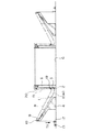
以下、本発明のケーブルドーム屋根の構築工法を図面に基づいて説明する。図1および図2は本発明のケーブルドーム屋根の構築工法の第1実施の形態を示すもので、図1(A)は構築開始時の全体図、図1(B)はケーブルドーム屋根を設計形状よりも上位に吊り上げた状態の全体図、図1(C)は補助ケーブルを緩めたケーブルドーム屋根が設計形状にある最終段階の全体図、図2(A)は構築完了時のケーブルドーム屋根の全体平面図、図2(B)はその全体正断面図である。本発明の基本構成は、図1に示すように、多数の放射ケーブルとリングケーブルとから組み合わされ、外周が躯体4上に設置される略円形のドーナツ形状から構成されたケーブルドーム屋根1の構築工法であって、地組されたケーブルドーム屋根1の外周を躯体4上にて支持するとともに、内周側を仮設構台6に沿って吊り上げるようにしたケーブルドーム屋根1の構築工法において、前記各放射ケーブル1Aを多数の吊り部材11を連結した補助ケーブル8を介して吊り上げることを特徴とする。
【0009】
以下詳細に説明する。図2(A)の平面図に示すように、ケーブルドーム屋根1は略円形のドーナツ形状を呈している。図示の例では楕円形状に構成されている。ケーブルドーム屋根1は、多数の放射ケーブル1Aと、これらを円周方向の多数のリングケーブル1Bにて組み合わせたものを連結し、その内周側に内周テンションリング2を、外周側に外周コンプレッションリング3を設置、連結して構成したものである。そして、このように構成されたケーブルドーム屋根1は、その外周コンプレッションリング3を観客席等を構成する躯体4の外周に固定、接続し、図2(B)に示すような構築完了後の設計形状にあるケーブルドーム屋根1の自重すなわち設計形状の保形は、外周コンプレッションリング3の圧縮と内周テンションリング2の張力によって受け持つものである。これら略円形状の内周テンションリング2や外周コンプレッションリング3は、微視的に見れば多数のユニットから構成された多角形状から構成されてもよいことは言うまでもないことである。
【0010】
図1(A)に示すように、多数の放射ケーブル1Aとこれらを円周方向の多数のリングケーブル1Bにて組み合わせたケーブルドーム屋根1は、基礎である地上Gにて地組みされる。躯体4の外周最上部に、ケーブルドーム屋根1における各放射ケーブル1Aの外周に連結した外周コンプレッションリング3を固定(揺動可能にピン接続等)する。14は放射ケーブル1Aを引き込むための緊張用ジャッキであるが、本発明では、後述する補助ケーブル8の存在により、緊張用ジャッキ14を小型でよいか設置しなくても済むものである。各放射ケーブル1Aの内周側は内周テンションリング2により連結されるとともに、各放射ケーブル1Aの上方に配設して張設される補助ケーブル8の内周側とを、リングビーム5により連結する。
【0011】
各補助ケーブル8の中間部には適宜本数の吊り部材11を介して放射ケーブル1Aが吊下され、補助ケーブル8の外周端部は躯体4の外周最上部に設置されたポスト9の上端部に軸支された滑車10にガイドされて延長垂下され、滑車12により水平方向に変換されて地上G上に設置されたウインチ13によって牽引される。補助ケーブル8の内周端部は、前記内周テンションリング2の内周側に連結されたリングビーム5に接続される。該リングビーム5の内周の地上Gには内周テンションリング2の内周形状に対応した平面形状の仮設構台6が仮設され、該仮設構台6の上端部にはジャッキ等の吊上装置7が設置される。該吊上装置7と前記リングビーム5のとの間には吊上用ワイヤ15が接続されて、吊上装置7の張力T1による牽引によりリングビーム5を吊り上げて、ケーブルドーム屋根1全体を図1(B)に示すようにリフトアップしていく。
【0012】
ケーブルドーム屋根1のリフトアップ作業中には、放射ケーブル1Aおよび補助ケーブル8は、リフトアップに連れて長さが変化しつつ、放射ケーブル1Aの自重を支持する役割を有するため、特に補助ケーブル8は一定の張力に保持される必要があり、そのため、前述したように、補助ケーブル8の延長垂下部分を地上G上に設置されたウインチ13によって一定の張力T2にて牽引できるように構成している。
【0013】
さらに、該補助ケーブル8の内周端部はリングビーム5に連結され、補助ケーブル8からの反力をリングビーム5で負担するように構成している。なお、リングビーム5の平面形状は、前記内周テンションリング2の形状と同じく楕円形状に構成されるが、補助ケーブル8からの反力を軸力として伝えるためには、好適には円形に近い方が望ましい。楕円形状であると、補助ケーブル8からの反力がリングビーム5に曲げ力も作用する(したがって、リングビーム5は円形に近接させるとよい)。
【0014】
このような状況下にて、仮設構台6の上端部に設置した吊上装置7により吊上用ワイヤ15を牽引してリングビーム5を吊り上げ、図1(B)に示すように、放射ケーブル1Aを設計形状より上方までほぼ水平状に吊り上げた後、ケーブルドーム屋根1における緊張用ジャッキ14を取り外す等(緊張用ジャッキ14は構築完了後の張力調整用として残すこともできる)して、放射ケーブル1Aの外周側と外周コンプレッションリング3とを接続する。つまり、放射ケーブル1Aは設計長さより短い状態にて外周コンプレッションリング3と接続されるのである。
【0015】
このような状態にて、図1(C)に示すように、吊上装置7の牽引を解除して張力T3にて繰り出すとともに、補助ケーブル8における延長垂下部分の牽引を解除して張力T4にて繰り出すことで、補助ケーブル8による放射ケーブル1Aの自重支持が解除される。これによって、自重により放射ケーブル1Aが設計形状位置まで降下して、放射ケーブル1A自体に張力が付与され、ケーブルドーム屋根1において、外周コンプレッションリング3に圧縮力が作用するとともに、内周テンションリング2に張力が作用して、ケーブルドーム屋根1がその自重によって安定して設計形状に維持されることになる。詳述はしないが、放射ケーブル1Aとリングケーブル1Bとで画成される区画毎に防水膜が張設される。
【0016】
図3は本発明のケーブルドーム屋根の構築工法の第2実施の形態を示す構築開始時の全体図である。本実施の形態のものは、基本的には前記第1実施の形態のものと同様であるが、放射ケーブル1Aの自重を支持する補助ケーブル8の張力を一定のT2’に保つために、補助ケーブル8における延長垂下部分にカウンタウェイト16を吊り下げたものである。該カウンタウェイト16の自重をもって補助ケーブル8に一定の張力T2’を付与するものである。本実施の形態では、滑車やウインチ等が不要で、張力付与手段が簡素化される。リフトアップ作業の完了時には、補助ケーブル8の長さが短くなった分だけカウンタウェイト16が地上Gに近接するので、地上Gにてカウンターウェイト16を回収することができる。張力付与手段以外の構成および吊上げによる構築方法は前記第1実施の形態のものと同様であるので説明は省略する。
【0017】
図4は本発明のケーブルドーム屋根の構築工法の第3実施の形態を示す構築開始時の全体図である。本実施の形態のものは、補助ケーブル8の張力付与と本設ケーブルである放射ケーブル1Aのリフトアップとを仮設構台6の内周側の地上Gに設置したウインチ13のみにて行えるように構成したものである。放射ケーブル1Aの自重を支持する補助ケーブル8の外周側端部を、躯体4の外周最上部のポスト9における上端部に固定点Pにて固定するとともに、内周側端部を延長して吊上用ワイヤ15とし、該ワイヤ15を放射ケーブル1Aの内周側に連結されたリングビーム5の上端部に軸支された滑車19に通し、さらにワイヤ15を仮設構台6の上端部に設置した滑車17、18を通して下降させ、地上Gにおける滑車12により水平状に変換してウインチ13により牽引する。
【0018】
このような構成により、躯体4の外周側のスペースに制限があるような敷地内での施工の場合でも、仮設構台6の内部に設置されたウインチ13のみを牽引することで、補助ケーブル8の延長部を構成する吊上用ワイヤ15の中間部がリングビーム5の上端部に軸支された滑車19の存在によって滑車装置が構成され、補助ケーブル8を含むケーブルドーム屋根1を、補助ケーブル8に一定の張力T1を維持したままで1/2の吊上力によってリフトアップすることが可能となる。
【0019】
図5は本発明のケーブルドーム屋根の構築工法の第4実施の形態を示す構築開始時の全体図である。本実施の形態のものは、補助ケーブル8の張力付与と本設ケーブルである放射ケーブル1Aのリフトアップとを躯体4の外周側の地上Gに設置したウインチ13のみにて行えるように構成したものである。放射ケーブル1Aの自重を支持する補助ケーブル8の内周側端部を延長して吊上用ワイヤ15とし、該ワイヤ15を放射ケーブル1Aの内周側に連結されたリングビーム5の上端部に軸支された滑車19に通して上昇させるとともに、仮設構台6の上端部に設置した滑車20を通して下降させてリングビーム5の適宜部位にその端部を固定する。一方、補助ケーブル8の外周側端部を延長垂下させて、地上Gにおける滑車12により水平状に変換してウインチ13により牽引する。
【0020】
なお、前記滑車19と20とで構成される滑車装置は、より小さな吊上力にてリフトアップできるように、2個以上の多数の滑車間に吊上用ワイヤ15を掛け回すように構成することもできる。このような構成により、躯体4の外周側の地上Gにおけるウインチ13のみを牽引することで、補助ケーブル8の延長部を構成する吊上用ワイヤ15が複数の滑車からなる滑車装置を構成するので、補助ケーブル8を含むケーブルドーム屋根1を、補助ケーブル8に一定の張力T5を維持したままでより小さな吊上力によってリフトアップすることが可能となる。
【0021】
以上、本発明の各実施の形態について説明してきたが、本発明の趣旨の範囲内で、ケーブルドーム屋根の形状(円形、楕円、多角形等)、形式(放射ケーブルとリングケーブルとの交差形態、例えば亀甲状であってもよい)、躯体の形状、形式、ケーブルドーム屋根における外周コンプレッションリングの支持形態、仮設構台の形状、形式、補助ケーブルの種類およびその吊り部材を介した放射ケーブルの吊上げ形態、補助ケーブルへの張力を付与形態(ウインチ、カウンターウェイトやばね等)、内周テンションリングおよび外周コンプレッションリングならびにリングビームの形状、形式およびそれらのケーブルドーム屋根との間の連結形態、滑車装置の形状、形式およびその補助ケーブルとの関連構成等については適宜選択できる。
【0022】
【発明の効果】
以上、詳細に説明してきたように本発明によれば、多数の放射ケーブルとリングケーブルとから組み合わされ、外周が躯体上に設置される略円形のドーナツ形状から構成されたケーブルドーム屋根の構築工法であって、地組されたケーブルドーム屋根の外周を躯体上にて支持するとともに、内周側を仮設構台に沿って吊り上げるようにしたケーブルドーム屋根の構築工法において、前記各放射ケーブルを多数の吊り部材を連結した補助ケーブルを介して吊り上げるようにしたので、大規模のケーブルドーム屋根の構築の場合でも、放射ケーブルを緊張させるためのジャッキ等の引込み装置が不要、あるいは小型のものが使用できるので、コストが大幅に低減される。
【0023】
また、前記補助ケーブルに一定の張力を付与しつつ吊り上げることにより、リフトアップとともに長さが変化する補助ケーブルであっても、放射ケーブルの自重を安定して有効に支持できる。さらに、前記ケーブルドーム屋根の外周側を外周コンプレッションリングにより連結するとともに、ケーブルドーム屋根の内周側を内周テンションリングにより連結し、該内周テンションリングと補助ケーブルの内周側との間をリングビームにより連結した場合は、リフトアップの完了時には、外周コンプレッションリングに圧縮力が作用するとともに、内周テンションリングに張力が作用して、ケーブルドーム屋根がその自重によって安定して設計形状に維持され、しかも、補助ケーブルへの緊張力に伴う反力をリングビームに負担させることで、安定してケーブルドーム屋根をリフトアップするこができる。
【0024】
さらにまた、前記ケーブルドーム屋根の内周側を設計形状より高い位置まで吊り上げて前記コンプレッションリングと放射ケーブルとを連結した後、前記補助ケーブルの緊張を開放して設計形状まで下降させることにより、設計長さより短い長さでコンプレッションリングと放射ケーブルとを連結できるので、これらの連結後に、ケーブルドーム屋根を自重により降下させて容易に設計形状を得ることができる。かくして、本発明によれば、吊り上げる際のケーブルの自重および張力負担を少なくできて、小型の吊下装置にても大規模のドーム屋根の構築を可能にするケーブルドーム屋根の構築工法が提供される。
【図面の簡単な説明】
【図1】本発明のケーブルドーム屋根の構築工法の第1実施の形態を示すもので、図1(A)は構築開始時の全体図、図1(B)はケーブルドーム屋根を設計形状よりも上位に吊り上げた状態の全体図、図1(C)は補助ケーブルを緩めたケーブルドーム屋根が設計形状にある最終段階の全体図である。
【図2】同、図2(A)は構築完了時のケーブルドーム屋根の全体平面図、図2(B)はその全体正断面図である。
【図3】本発明のケーブルドーム屋根の構築工法の第2実施の形態を示す構築開始時の全体図である。
【図4】本発明のケーブルドーム屋根の構築工法の第3実施の形態を示す構築開始時の全体図である。
【図5】本発明のケーブルドーム屋根の構築工法の第4実施の形態を示す構築開始時の全体図である。
【図6】従来のケーブルドーム屋根の構築工法を示す説明図である。
【符号の説明】
1・・・・ケーブルドーム屋根
1A・・・・放射ケーブル
1B・・・・リングケーブル
2・・・・内周テンションリング
3・・・・外周コンプレッションリング
4・・・・躯体
5・・・・リングビーム
6・・・・仮設構台
7・・・・吊上装置(吊上用ジャッキ等)
8・・・・補助ケーブル
9・・・・ポスト
10・・・・滑車
11・・・・吊り部材
12・・・・滑車
13・・・・ウインチ
14・・・・緊張用ジャッキ
15・・・・吊上用ワイヤ
16・・・・カウンターウェイト
17〜20・・・滑車
G・・・・地上(基礎)
P・・・・固定点[0001]
TECHNICAL FIELD OF THE INVENTION
The present invention relates to a cable dome roof construction method comprising a combination of a large number of radiating cables and ring cables and having an outer circumference formed on a frame having a substantially circular donut shape, wherein the cable dome roof is laid. The present invention relates to a method for constructing a cable dome roof in which an outer periphery of a cable dome is supported on a frame and an inner peripheral side is suspended along a temporary gantry.
[0002]
[Prior art]
BACKGROUND ART Conventionally, there is a cable dome roof as a huge structure that covers spectator seats such as a stadium. The cable dome roof is being used frequently as a large dome type roof because it can support its own weight with a simple structure in which a large number of radiation cables and circumferential ring cables are connected and combined. Conventionally, as a construction method of this kind of cable dome roof, a jack is attached to each end of the radiating cable, and the radiating cable is tensioned by the operation of these jacks, thereby lifting the radiating cable to a predetermined height and constructing a design shape. Has been adopted. In such a conventional construction method, since the weight of the cable dome roof itself is large, a large number of large jacks are required, resulting in an increase in cost.
[0003]
Therefore, both ends of the erection cable that constitutes the cable dome roof are hung by a climbing device installed on the mast of a tower crane installed in the center of the building frame and a lifting device such as a guide post installed inside the outer periphery of the frame. There has been proposed a construction method of lowering and lifting up to a predetermined position (for example, see Patent Document 1 below).
[0004]
[Patent Document 1]
JP-A-59-88550 (Gazette, page 2, column 3, line 2 to line 12)
[0005]
[Problems to be solved by the invention]
As shown in FIG. 6, the load of the erection cable 101 at the time of lift-up is transferred to the climbing device 110 provided on the mast of the tower crane 108 and dispersed by the cable dome roof construction method described in Patent Document 1. As a result, the jack only needs to be strained by the flexure caused by the weight of the erection cable, and the jack needs to be a jack having a somewhat smaller capacity. However, in the case of construction of a large-scale cable dome roof, it goes without saying that the weight of the cable itself also increases, and the tension of the cable during tension also increases. The need to prepare large jacks was still unavoidable.
[0006]
Therefore, the present invention solves the problems of the conventional cable dome roof construction method, can reduce the weight of the cable itself and the tension load when lifting the cable dome roof. It is an object of the present invention to provide a cable dome roof construction method that enables construction.
[0007]
[Means for Solving the Problems]
Therefore, the present invention is a method of constructing a cable dome roof composed of a large number of radiating cables and ring cables and having a substantially circular donut shape whose outer periphery is installed on a skeleton, In the method of constructing a cable dome roof in which the outer periphery of the dome roof is supported on the skeleton and the inner peripheral side is lifted along the temporary gantry, each of the radiation cables is connected via an auxiliary cable connecting a number of suspension members. It is characterized by being lifted. Further, the present invention is characterized in that the auxiliary cable is lifted while applying a constant tension. The present invention also relates to an outer peripheral side of the cable dome roof connected by an outer peripheral compression ring, an inner peripheral side of the cable dome roof connected by an inner peripheral tension ring, and an inner peripheral side of the inner peripheral tension ring and an inner peripheral side of the auxiliary cable. Are connected by a ring beam. Further, the present invention provides that, after the inner peripheral side of the cable dome roof is lifted to a position higher than a design shape and the compression ring and the radiation cable are connected, the tension of the auxiliary cable is released and lowered to the design shape. These are the features and these are the means for solving the problems.
[0008]
Embodiment
Hereinafter, the construction method of the cable dome roof of the present invention will be described with reference to the drawings. 1 and 2 show a first embodiment of a cable dome roof construction method according to the present invention. FIG. 1 (A) is an overall view at the start of construction, and FIG. 1 (B) designs a cable dome roof. An overall view of the cable dome suspended above the shape, FIG. 1 (C) is an overall view of the final stage where the cable dome roof with the auxiliary cable loosened is in the design shape, and FIG. 2 (A) is a cable dome roof at the time of completion of construction 2 (B) is an overall front sectional view of FIG. As shown in FIG. 1, the basic configuration of the present invention is to construct a cable dome roof 1 composed of a plurality of radiating cables and ring cables and having a substantially circular donut shape whose outer periphery is installed on a skeleton 4. In the construction method of the cable dome roof 1 in which the outer periphery of the cable dome roof 1 laid on the ground is supported on the frame 4 and the inner peripheral side is lifted along the temporary gantry 6, The radiating cable 1A is lifted up via an auxiliary cable 8 to which a number of hanging members 11 are connected.
[0009]
This will be described in detail below. As shown in the plan view of FIG. 2A, the cable dome roof 1 has a substantially circular donut shape. In the illustrated example, it is configured in an elliptical shape. The cable dome roof 1 connects a large number of radiating cables 1A and a combination of these cables with a large number of circumferential ring cables 1B, an inner circumferential tension ring 2 on the inner circumferential side, and an outer circumferential compression on the outer circumferential side. The ring 3 is installed and connected. In the cable dome roof 1 configured as described above, the outer peripheral compression ring 3 is fixed and connected to the outer periphery of the frame 4 constituting the audience seats and the like, and the design after the completion of the construction as shown in FIG. The weight of the cable dome roof 1 in the shape, that is, the shape preservation of the design shape, is covered by the compression of the outer compression ring 3 and the tension of the inner tension ring 2. Needless to say, these substantially circular inner peripheral tension rings 2 and outer peripheral compression rings 3 may be composed of a polygonal shape composed of a large number of units when viewed microscopically.
[0010]
As shown in FIG. 1A, a cable dome roof 1 in which a large number of radiating cables 1A and these are combined with a large number of circumferential ring cables 1B is laid on a ground G as a foundation. An outer circumference compression ring 3 connected to the outer circumference of each radiating cable 1A in the cable dome roof 1 is fixed (swingably pin-connected, etc.) to the outermost top of the frame 4. Reference numeral 14 denotes a tensioning jack for drawing in the radiation cable 1A. In the present invention, the tensioning jack 14 may be small in size or need not be installed due to the presence of the auxiliary cable 8 described later. The inner peripheral side of each radiating cable 1A is connected by an inner peripheral tension ring 2, and the inner peripheral side of an auxiliary cable 8 arranged and extended above each radiating cable 1A is connected by a ring beam 5. I do.
[0011]
A radiation cable 1A is suspended from an intermediate portion of each auxiliary cable 8 via an appropriate number of suspension members 11, and the outer peripheral end of the auxiliary cable 8 is connected to the upper end of a post 9 installed on the outermost top of the frame 4. The pulley 12 is guided and extended by a pulley 10 supported by a shaft, is converted into a horizontal direction by a pulley 12, and is pulled by a winch 13 installed on the ground G. The inner peripheral end of the auxiliary cable 8 is connected to the ring beam 5 connected to the inner peripheral side of the inner peripheral tension ring 2. A temporary gantry 6 having a planar shape corresponding to the inner peripheral shape of the inner peripheral tension ring 2 is temporarily provided on the ground G on the inner periphery of the ring beam 5, and a lifting device 7 such as a jack is provided on an upper end of the temporary gantry 6. Is installed. A lifting wire 15 is connected between the lifting device 7 and the ring beam 5, and the ring beam 5 is lifted by the pulling of the lifting device 7 by the tension T1, so that the entire cable dome roof 1 is illustrated. Lift up as shown in FIG.
[0012]
During the lift-up operation of the cable dome roof 1, the radiating cable 1A and the auxiliary cable 8 have a role of supporting the own weight of the radiating cable 1A while their lengths change with the lift-up. Is required to be maintained at a constant tension. Therefore, as described above, the extension hanging portion of the auxiliary cable 8 is configured to be pulled by the winch 13 installed on the ground G at a constant tension T2. I have.
[0013]
Further, the inner peripheral end of the auxiliary cable 8 is connected to the ring beam 5 so that the reaction force from the auxiliary cable 8 is borne by the ring beam 5. The planar shape of the ring beam 5 is configured to be elliptical like the shape of the inner peripheral tension ring 2, but is preferably close to a circle in order to transmit the reaction force from the auxiliary cable 8 as an axial force. Is more desirable. With an elliptical shape, the reaction force from the auxiliary cable 8 also exerts a bending force on the ring beam 5 (therefore, the ring beam 5 should be close to a circle).
[0014]
In such a situation, the ring beam 5 is lifted by pulling the lifting wire 15 by the lifting device 7 installed at the upper end of the temporary gantry 6, and as shown in FIG. Is lifted almost horizontally above the design shape, and then the tensioning jack 14 in the cable dome roof 1 is removed (the tensioning jack 14 can be left for tension adjustment after the construction is completed), and the radiation cable 1A and the outer compression ring 3 are connected. That is, the radiation cable 1A is connected to the outer peripheral compression ring 3 in a state shorter than the designed length.
[0015]
In such a state, as shown in FIG. 1C, the lifting of the lifting device 7 is released and the lifting is performed with the tension T3, and the pulling of the extended hanging portion of the auxiliary cable 8 is released and the tension is reduced to the tension T4. By doing so, the support of the radiating cable 1A by its own weight by the auxiliary cable 8 is released. As a result, the radiation cable 1A descends to the design shape position by its own weight, and tension is applied to the radiation cable 1A itself. In the cable dome roof 1, a compressive force acts on the outer compression ring 3 and the inner tension ring 2 And the cable dome roof 1 is stably maintained in the designed shape by its own weight. Although not described in detail, a waterproof film is stretched for each section defined by the radiation cable 1A and the ring cable 1B.
[0016]
FIG. 3 is an overall view of a cable dome roof construction method according to a second embodiment of the present invention at the start of construction. This embodiment is basically the same as the first embodiment, except that the auxiliary cable 8 for supporting the weight of the radiating cable 1A is maintained at a constant T2 '. A counter weight 16 is suspended from an extended hanging portion of the cable 8. The constant weight T2 'is applied to the auxiliary cable 8 by the weight of the counter weight 16. In the present embodiment, pulleys and winches are not required, and the tension applying means is simplified. When the lift-up operation is completed, the counterweight 16 approaches the ground G by an amount corresponding to the shortened length of the auxiliary cable 8, so that the counterweight 16 can be collected on the ground G. The configuration other than the tension applying means and the construction method by lifting are the same as those of the first embodiment, and therefore the description is omitted.
[0017]
FIG. 4 is an overall view of a cable dome roof construction method according to a third embodiment of the present invention at the start of construction. In the present embodiment, the tension is applied to the auxiliary cable 8 and the lift-up of the radiation cable 1A, which is a permanent cable, can be performed only by the winch 13 installed on the ground G on the inner peripheral side of the temporary gantry 6. It was done. The outer end of the auxiliary cable 8 that supports the weight of the radiating cable 1A is fixed at the fixing point P to the upper end of the uppermost post 9 of the frame 4 at the fixing point P, and the inner end is extended. The upper wire 15 was passed through a pulley 19 pivotally supported by the upper end of the ring beam 5 connected to the inner peripheral side of the radiating cable 1A, and the wire 15 was set on the upper end of the temporary gantry 6. It is lowered through the pulleys 17 and 18, converted to a horizontal state by the pulley 12 on the ground G, and towed by the winch 13.
[0018]
With such a configuration, even in the case of construction on a site where the space on the outer peripheral side of the skeleton 4 is limited, by pulling only the winch 13 installed inside the temporary gantry 6, the auxiliary cable 8 A pulley device is formed by the presence of a pulley 19 in which an intermediate portion of the lifting wire 15 constituting the extension portion is pivotally supported on an upper end portion of the ring beam 5, and the cable dome roof 1 including the auxiliary cable 8 is connected to the auxiliary cable 8. It is possible to lift up with a half lifting force while maintaining a constant tension T1.
[0019]
FIG. 5 is an overall view of a cable dome roof construction method according to a fourth embodiment of the present invention at the start of construction. In the present embodiment, the tension is applied to the auxiliary cable 8 and the lift-up of the radiation cable 1A, which is a permanent cable, can be performed only by the winch 13 installed on the ground G on the outer peripheral side of the frame 4. It is. The inner peripheral end of the auxiliary cable 8 that supports the weight of the radiating cable 1A is extended to form a lifting wire 15, and the wire 15 is attached to the upper end of the ring beam 5 connected to the inner peripheral side of the radiating cable 1A. The end is fixed to an appropriate portion of the ring beam 5 by lowering through a pulley 20 installed at the upper end of the temporary gantry 6 while raising the same through a pulley 19 supported by a shaft. On the other hand, the outer peripheral end of the auxiliary cable 8 is extended and suspended, converted to a horizontal state by the pulley 12 on the ground G, and pulled by the winch 13.
[0020]
The pulley device composed of the pulleys 19 and 20 is configured so that the lifting wire 15 is looped between two or more pulleys so that the lift can be lifted up with a smaller lifting force. You can also. With such a configuration, by pulling only the winch 13 on the ground G on the outer peripheral side of the frame 4, the lifting wire 15 constituting the extension of the auxiliary cable 8 constitutes a pulley device including a plurality of pulleys. The cable dome roof 1 including the auxiliary cable 8 can be lifted up with a smaller lifting force while maintaining a constant tension T5 on the auxiliary cable 8.
[0021]
The embodiments of the present invention have been described above. However, within the scope of the present invention, the shape (circular, elliptical, polygonal, etc.) and type (intersection of radiation cable and ring cable) of the cable dome roof , For example, may be a turtle-shaped), the shape and type of the skeleton, the form of support of the outer peripheral compression ring on the cable dome roof, the shape and type of the temporary gantry, the type of auxiliary cable, and the lifting of the radiating cable via the hanging member Form, form to apply tension to auxiliary cable (winch, counterweight, spring, etc.), shape and form of inner tension ring and outer compression ring and ring beam, form of connection between them and cable dome roof, pulley device The shape, type, and related configuration of the auxiliary cable can be selected as appropriate.
[0022]
【The invention's effect】
As described above in detail, according to the present invention, a method of constructing a cable dome roof composed of a plurality of radiating cables and ring cables and having a substantially circular donut shape whose outer periphery is installed on a skeleton. In the method of constructing a cable dome roof in which the outer periphery of the cable dome roof laid on the ground is supported on the frame and the inner peripheral side is lifted along the temporary gantry, a large number of the radiation cables are used. Since the suspension member is suspended via the auxiliary cable connected to the suspension member, even in the case of constructing a large-scale cable dome roof, a retracting device such as a jack for tensioning the radiation cable is unnecessary or a small one can be used. Therefore, the cost is greatly reduced.
[0023]
In addition, by lifting the auxiliary cable while applying a constant tension thereto, even if the auxiliary cable changes in length as it is lifted up, the weight of the radiating cable can be stably and effectively supported. Further, the outer peripheral side of the cable dome roof is connected by an outer peripheral compression ring, the inner peripheral side of the cable dome roof is connected by an inner peripheral tension ring, and the space between the inner peripheral tension ring and the inner peripheral side of the auxiliary cable is connected. When connected by a ring beam, when lift-up is completed, compressive force acts on the outer compression ring and tension acts on the inner tension ring, and the cable dome roof stably maintains its design shape by its own weight. In addition, by causing the ring beam to bear the reaction force caused by the tension applied to the auxiliary cable, the cable dome roof can be stably lifted up.
[0024]
Furthermore, after the inner peripheral side of the cable dome roof is lifted to a position higher than the design shape and the compression ring and the radiating cable are connected, the tension of the auxiliary cable is released and lowered to the design shape, thereby reducing the design. Since the compression ring and the radiating cable can be connected with a length shorter than the length, the cable dome roof can be lowered by its own weight after these connections to easily obtain a design shape. Thus, according to the present invention, there is provided a method of constructing a cable dome roof that can reduce the weight of the cable and the strain on the cable when it is lifted, and that enables the construction of a large-scale dome roof even with a small suspension device. You.
[Brief description of the drawings]
FIG. 1 shows a first embodiment of a cable dome roof construction method according to the present invention. FIG. 1 (A) is an overall view at the start of construction, and FIG. FIG. 1C is an overall view of the final stage in which the cable dome roof with the auxiliary cable loosened is in the designed shape.
FIG. 2 (A) is an overall plan view of the cable dome roof at the time of completion of construction, and FIG. 2 (B) is an overall front sectional view thereof.
FIG. 3 is an overall view of a cable dome roof construction method according to a second embodiment of the present invention at the start of construction.
FIG. 4 is an overall view of a cable dome roof construction method according to a third embodiment of the present invention at the start of construction.
FIG. 5 is an overall view at the start of construction showing a fourth embodiment of the cable dome roof construction method of the present invention.
FIG. 6 is an explanatory view showing a conventional cable dome roof construction method.
[Explanation of symbols]
1 Cable dome roof 1A Radiation cable 1B Ring cable 2 Inner circumference tension ring 3 Outer circumference compression ring 4 Body 5 Ring beam 6 Temporary gantry 7 Lifting device (lifting jack, etc.)
8, auxiliary cable 9, post 10, pulley 11, suspension member 12, pulley 13, winch 14, tension jack 15, -Lifting wire 16-Counterweight 17-20-Pulley G-Ground (foundation)
P ... fixed point