JP2004336983A - Power output apparatus and automobile equipped therewith - Google Patents
Power output apparatus and automobile equipped therewith Download PDFInfo
- Publication number
- JP2004336983A JP2004336983A JP2004036305A JP2004036305A JP2004336983A JP 2004336983 A JP2004336983 A JP 2004336983A JP 2004036305 A JP2004036305 A JP 2004036305A JP 2004036305 A JP2004036305 A JP 2004036305A JP 2004336983 A JP2004336983 A JP 2004336983A
- Authority
- JP
- Japan
- Prior art keywords
- electric machine
- rotating electric
- internal combustion
- combustion engine
- shaft
- Prior art date
- Legal status (The legal status is an assumption and is not a legal conclusion. Google has not performed a legal analysis and makes no representation as to the accuracy of the status listed.)
- Granted
Links
- 238000002485 combustion reaction Methods 0.000 claims abstract description 175
- 238000006243 chemical reaction Methods 0.000 claims description 28
- 238000001514 detection method Methods 0.000 claims description 12
- 230000001172 regenerating effect Effects 0.000 claims description 12
- 230000007246 mechanism Effects 0.000 abstract description 24
- 230000005540 biological transmission Effects 0.000 description 31
- 238000000034 method Methods 0.000 description 21
- 230000008569 process Effects 0.000 description 19
- 238000010586 diagram Methods 0.000 description 13
- 230000035939 shock Effects 0.000 description 10
- 239000000446 fuel Substances 0.000 description 9
- 238000002347 injection Methods 0.000 description 6
- 239000007924 injection Substances 0.000 description 6
- 239000000203 mixture Substances 0.000 description 4
- 230000004048 modification Effects 0.000 description 4
- 238000012986 modification Methods 0.000 description 4
- 239000007858 starting material Substances 0.000 description 4
- 230000009467 reduction Effects 0.000 description 3
- 238000004891 communication Methods 0.000 description 2
- 230000000694 effects Effects 0.000 description 2
- 238000004880 explosion Methods 0.000 description 2
- 230000001360 synchronised effect Effects 0.000 description 2
- 239000004215 Carbon black (E152) Substances 0.000 description 1
- 230000004323 axial length Effects 0.000 description 1
- 230000008859 change Effects 0.000 description 1
- 238000013016 damping Methods 0.000 description 1
- 230000007423 decrease Effects 0.000 description 1
- 230000002542 deteriorative effect Effects 0.000 description 1
- 230000009699 differential effect Effects 0.000 description 1
- 238000007599 discharging Methods 0.000 description 1
- 229930195733 hydrocarbon Natural products 0.000 description 1
- 150000002430 hydrocarbons Chemical class 0.000 description 1
- 230000006872 improvement Effects 0.000 description 1
Images


Classifications
-
- Y—GENERAL TAGGING OF NEW TECHNOLOGICAL DEVELOPMENTS; GENERAL TAGGING OF CROSS-SECTIONAL TECHNOLOGIES SPANNING OVER SEVERAL SECTIONS OF THE IPC; TECHNICAL SUBJECTS COVERED BY FORMER USPC CROSS-REFERENCE ART COLLECTIONS [XRACs] AND DIGESTS
- Y02—TECHNOLOGIES OR APPLICATIONS FOR MITIGATION OR ADAPTATION AGAINST CLIMATE CHANGE
- Y02T—CLIMATE CHANGE MITIGATION TECHNOLOGIES RELATED TO TRANSPORTATION
- Y02T10/00—Road transport of goods or passengers
- Y02T10/60—Other road transportation technologies with climate change mitigation effect
- Y02T10/62—Hybrid vehicles
Abstract
Description
本発明は、動力出力装置およびこれを搭載する自動車に関し、詳しくは、駆動軸に動力を出力する動力出力装置およびこれを搭載する自動車に関する。 The present invention relates to a power output device and a vehicle equipped with the same, and more particularly, to a power output device that outputs power to a drive shaft and a vehicle equipped with the same.
従来、この種の動力出力装置としては、エンジンと、エンジンの出力軸に接続されたプラネタリギヤと、プラネタリギヤに接続された第1のモータと、同じくプラネタリギアに接続されると共に駆動軸に接続された第2のモータとを備えるものが提案されている。この装置では、エンジンから出力された動力を第1のモータと第2のモータとによりトルク変換して駆動軸に出力することができる。このとき、エンジンを効率のよい運転ポイントで運転させるものとすれば、装置全体のエネルギ効率を向上させることができる。 Conventionally, as a power output device of this type, an engine, a planetary gear connected to an output shaft of the engine, a first motor connected to the planetary gear, and a drive shaft connected to the planetary gear and also to the drive shaft. A device having a second motor has been proposed. In this device, the power output from the engine can be converted into torque by the first motor and the second motor and output to the drive shaft. At this time, if the engine is operated at an efficient operation point, the energy efficiency of the entire apparatus can be improved.
こうした動力出力装置では、エンジンから出力される動力を用いて第2のモータで回生すると共に第1のモータを力行して駆動軸に動力を出力するエネルギ循環が生じて、効率を悪化させる場合がある。 In such a power output device, there is a case in which energy is recirculated by the second motor using the power output from the engine, and power is output to the drive shaft by powering the first motor, thereby deteriorating efficiency. is there.
なお、本出願人は、上述した課題の少なくとも一部を解決する手法として、エンジンの出力軸と駆動軸と第1のモータの回転軸とをプラネタリギヤで結合し、第2のモータの回転軸を第1クラッチを介してエンジンの出力軸に連結すると共に第2クラッチを介して駆動軸に連結し、駆動軸の回転数がエンジンの回転数よりも大きいときには第1クラッチをオンすると共に第2クラッチをオフし、駆動軸の回転数がエンジンの回転数よりも小さいときには第1クラッチをオフすると共に第2クラッチをオンすることにより、第1のモータと第2のモータとの間でエネルギ循環が生じるのを防止する技術を提案している(特許文献1参照)。 In addition, as a method of solving at least a part of the above-described problem, the present applicant connects an output shaft of an engine, a drive shaft, and a rotation shaft of a first motor with a planetary gear, and rotates a rotation shaft of a second motor. The first clutch is connected to the output shaft of the engine via the first clutch and connected to the drive shaft via the second clutch. When the rotation speed of the drive shaft is higher than the rotation speed of the engine, the first clutch is turned on and the second clutch is Is turned off, and when the rotation speed of the drive shaft is lower than the rotation speed of the engine, the first clutch is turned off and the second clutch is turned on, whereby energy circulation between the first motor and the second motor is performed. A technique for preventing such a phenomenon has been proposed (see Patent Document 1).
このように動力出力装置のエネルギ循環を防止して装置全体のエネルギ効率をより向上させることは重要な課題として考えられており、更なる改善あるいは異なる構成の動力出力装置への適用が求められている。 As described above, it is considered that it is important to prevent the energy circulation of the power output device and further improve the energy efficiency of the entire device as an important issue, and further improvement or application to a power output device having a different configuration is required. I have.
本発明の動力出力装置およびこれを搭載する自動車は、第1の回転電機と第2の回転電機との間のエネルギ循環を防止してエネルギ効率をより向上させることを目的の一つとする。また、本発明の動力出力装置およびこれを搭載する自動車は、内燃機関を始動する際や停止させる際に、車両に振動が生じるのを抑制することを目的の一つとする。さらに、本発明の動力出力装置およびこれを搭載する自動車は、内燃機関を始動する際や停止させる際に駆動軸に出力する駆動力を維持することを目的の一つとする。また、本発明の動力出力装置およびこれを搭載する自動車は、装置の小型化を図ることを目的の一つとする。 It is an object of the power output device of the present invention and an automobile equipped with the same to prevent energy circulation between the first rotating electric machine and the second rotating electric machine to further improve energy efficiency. Another object of the power output device of the present invention and an automobile equipped with the same are to suppress the occurrence of vibrations in the vehicle when starting or stopping the internal combustion engine. Still another object of the power output device of the present invention and a vehicle equipped with the same are to maintain a driving force output to a drive shaft when starting or stopping the internal combustion engine. Another object of the present invention is to reduce the size of the power output device and the vehicle equipped with the power output device.
本発明の動力出力装置およびこれを搭載する自動車は、上述の目的の少なくとも一部を達成するために以下の手段を採った。 The power output device of the present invention and an automobile equipped with the same employ the following means in order to at least partially achieve the above-described object.
本発明の第1の動力出力装置は、
駆動軸に動力を出力する動力出力装置であって、
内燃機関と、
発電可能な第1の回転電機と、
前記内燃機関の出力軸に接続された第1の軸と前記第1の回転電機の回転軸に接続された第2の軸と前記駆動軸に接続された第3の軸とを有し、これら3つの軸のうちのいずれか2軸に入出力される動力が決定されると残余の1軸に入出力される動力が決定される3軸式の動力入出力手段と、
前記駆動軸に接続された第2の回転電機と、
前記内燃機関の出力軸または前記第1の軸に接続された発電可能な第3の回転電機と、
前記第1の回転電機と前記第2の回転電機と前記第3の回転電機との間で電力をやり取り可能に接続された電力系統と
を備えることを要旨とする。
The first power output device of the present invention is:
A power output device that outputs power to a drive shaft,
An internal combustion engine,
A first rotating electric machine capable of generating electric power,
A first shaft connected to an output shaft of the internal combustion engine, a second shaft connected to a rotation shaft of the first rotating electric machine, and a third shaft connected to the drive shaft; Three-axis power input / output means for determining power input / output to any two of the three axes and determining power input / output to the remaining one axis;
A second rotating electric machine connected to the drive shaft;
A third rotating electric machine capable of generating power connected to the output shaft or the first shaft of the internal combustion engine,
A power system connected to the first rotating electrical machine, the second rotating electrical machine, and the third rotating electrical machine so that power can be exchanged between the first rotating electrical machine, the second rotating electrical machine, and the third rotating electrical machine.
この本発明の第1の動力出力装置では、内燃機関から出力される動力を第1の回転電機と第2の回転電機とを介して駆動軸に出力したり、内燃機関から出力される動力を第3の回転電機と第1の回転電機とを介して駆動軸に出力したりすることが可能となるから、エネルギ循環が生じるのを回避することが可能となり、装置全体のエネルギ効率をより向上させることが可能となる。 In the first power output device of the present invention, the power output from the internal combustion engine is output to the drive shaft via the first rotary electric machine and the second rotary electric machine, or the power output from the internal combustion engine is output. Since it is possible to output to the drive shaft via the third rotating electric machine and the first rotating electric machine, it is possible to avoid the occurrence of energy circulation, and to further improve the energy efficiency of the entire apparatus. It is possible to do.
こうした本発明の第1の動力出力装置において、前記第1の回転電機の回転軸の回転状態または前記第1の回転電機の回転軸に接続された第2の軸の回転状態に基づいて前記内燃機関と前記第1の回転電機と前記第2の回転電機と前記第3の回転電機とを運転制御する運転制御手段を備えるものとすることもできる。この態様の本発明の第1の動力出力装置において、前記運転制御手段は、前記第1の回転電機の回転軸に接続された第2の軸が前記内燃機関の出力軸に接続された第1の軸と同方向に回転するときには、前記内燃機関から出力される動力を前記第1の回転電機と前記第2の回転電機とによりトルク変換することにより要求動力が前記駆動軸に出力されるよう前記内燃機関と前記第1の回転電機と前記第2の回転電機とを運転制御し、前記第1の回転電機の回転軸に接続された第2の軸が前記内燃機関の出力軸に接続された第1の軸と逆方向に回転するときには、前記内燃機関からの動力を前記第3の回転電機と前記第1の回転電機とによりトルク変換することにより要求動力が前記駆動軸に出力されるよう前記内燃機関と前記第1の回転電機と前記第3の回転電機とを運転制御する手段であるものとすることもできる。こうすれば、エネルギ循環が生じるのをより適切に回避でき、装置全体のエネルギ効率をより向上させることができる。この態様の本発明の第1の動力出力装置において、前記運転制御手段は、前記第1の回転電機の回転軸に接続された第2の軸が前記内燃機関の出力軸に接続された第1の軸と同方向に回転するときには、前記第1の回転電機を回生運転すると共に回生された電力を用いて前記第2の回転電機を力行運転するよう制御し、前記第1の回転電機の回転軸に接続された第2の軸が前記内燃機関の出力軸に接続された第1の軸と逆方向に回転するときには、前記第3の回転電機を回生運転すると共に回生された電力を用いて前記第1の回転電機を力行運転するよう運転制御する手段であるものとすることもできる。 In the first power output device according to the present invention, the internal combustion engine may be configured to perform the internal combustion based on the rotation state of the rotation shaft of the first rotating electric machine or the rotation state of the second shaft connected to the rotation shaft of the first rotating electric machine. Operation control means for controlling operation of the engine, the first rotating electric machine, the second rotating electric machine, and the third rotating electric machine may be provided. In the first power output apparatus according to the aspect of the present invention, the operation control means may include a first shaft having a second shaft connected to a rotating shaft of the first rotating electric machine connected to an output shaft of the internal combustion engine. When the motor rotates in the same direction as the shaft, the power output from the internal combustion engine is torque-converted by the first rotary electric machine and the second rotary electric machine so that the required power is output to the drive shaft. An operation control of the internal combustion engine, the first rotating electric machine, and the second rotating electric machine, wherein a second shaft connected to a rotating shaft of the first rotating electric machine is connected to an output shaft of the internal combustion engine. When the motor rotates in the direction opposite to the first shaft, the required power is output to the drive shaft by converting the power from the internal combustion engine into torque by the third rotating electric machine and the first rotating electric machine. The internal combustion engine and the first rotating electric machine May be assumed to be a unit that controls the operation of the said third rotating electric machine. This makes it possible to more appropriately avoid the occurrence of energy circulation, and to further improve the energy efficiency of the entire device. In the first power output apparatus according to the aspect of the present invention, the operation control means may include a first shaft having a second shaft connected to a rotating shaft of the first rotating electric machine connected to an output shaft of the internal combustion engine. When rotating in the same direction as the axis of the first rotating electric machine, the first rotating electric machine is controlled to perform a regenerative operation, and the second rotating electric machine is controlled to perform a power running operation by using the regenerated electric power. When the second shaft connected to the shaft rotates in the opposite direction to the first shaft connected to the output shaft of the internal combustion engine, the third rotating electric machine is regenerated and the regenerated electric power is used. A means for controlling the operation of the first rotating electric machine so as to perform the power running operation may be employed.
また、本発明の第1の動力出力装置において、前記運転制御手段は、前記内燃機関の始動が指示されたとき又は前記内燃機関の停止が指示されたとき、前記第3の回転電機の駆動により該内燃機関をモータリングして始動、または前記内燃機関の運転を停止すると共に前記第3の回転電機により該内燃機関の回転を停止するよう前記内燃機関と前記第3の回転電機とを運転制御する手段であるものとすることもできる。こうすれば、内燃機関を始動する際や停止する際に生じる得る車両の振動や駆動軸へのトルクショックを低減したりなくしたりすることができる。この態様の本発明の第1の動力出力装置において、前記運転制御手段は、要求動力が前記駆動軸に出力されるよう前記第2の回転電機を運転制御する手段であるものとすることもできる。こうすれば、第3の回転電機の駆動により内燃機関を始動しながら第2の回転電機を駆動して要求動力を駆動軸に出力することができる。また、第3の回転電機により内燃機関を始動する際に駆動軸へトルクショックが生じるのを低減するから、第2の回転電機によりスムーズに要求動力を駆動軸に出力することができる。 Further, in the first power output device of the present invention, the operation control means may control the drive of the third rotating electric machine when the start of the internal combustion engine is instructed or when the stop of the internal combustion engine is instructed. The internal combustion engine is started by motoring, or the operation of the internal combustion engine and the third rotating electric machine is controlled such that the operation of the internal combustion engine is stopped and the rotation of the internal combustion engine is stopped by the third rotating electric machine. It can also be a means to perform. This makes it possible to reduce or eliminate the vibration of the vehicle and the torque shock to the drive shaft, which may occur when the internal combustion engine is started or stopped. In the first power output apparatus according to the aspect of the present invention, the operation control means may be means for controlling the operation of the second rotating electric machine such that the required power is output to the drive shaft. . With this configuration, it is possible to output the required power to the drive shaft by driving the second rotating electric machine while starting the internal combustion engine by driving the third rotating electric machine. In addition, since the occurrence of torque shock on the drive shaft when the internal combustion engine is started by the third rotary electric machine is reduced, the required power can be smoothly output to the drive shaft by the second rotary electric machine.
さらに、本発明の第1の動力出力装置において、前記第3の回転電機の回転軸は、前記内燃機関の出力軸と一体的に回転するよう接続されてなるものとすることもできる。こうすれば、内燃機関と第3の回転電機との間でやり取りされる動力の伝達効率を高めることができる。 Further, in the first power output device of the present invention, the rotating shaft of the third rotating electric machine may be connected to rotate integrally with the output shaft of the internal combustion engine. With this configuration, it is possible to increase the transmission efficiency of power exchanged between the internal combustion engine and the third rotating electric machine.
また、本発明の第1の動力出力装置において、前記第3の回転電機の回転軸は、前記内燃機関の出力軸とベルトまたはギヤまたはチェーンを介して接続されてなるものとすることもできる。こうすれば、第3の回転電機を装置内の空きスペースに搭載することも可能となるから装置全体を小型化することも可能となる。 Further, in the first power output device of the present invention, a rotation shaft of the third rotating electric machine may be connected to an output shaft of the internal combustion engine via a belt, a gear, or a chain. With this configuration, the third rotating electric machine can be mounted in an empty space in the device, so that the entire device can be reduced in size.
本発明の第2の動力出力装置は、
駆動軸に動力を出力する動力出力装置であって、
内燃機関と、
発電可能な第1の回転電機と、
前記内燃機関の出力軸に接続された第1の軸と前記第1の回転電機に接続された第2の軸と前記駆動軸に接続された第3の軸とを有し、これら3つの軸のうちのいずれか2軸に入出力される動力が決定されると残余の1軸に入出力される動力が決定される3軸式の動力入出力手段と、
第2の回転電機と、
前記第2の回転電機の回転軸と前記内燃機関の出力軸とを接続および接続解除が可能な第1の接続解除手段と、
前記第2の回転電機の回転軸と前記駆動軸とを接続および接続解除が可能な第2の接続解除手段と、
前記第1の回転電機の回転軸の回転状態または前記第1の回転電機の回転軸に接続された第2の軸の回転状態に基づいて前記第1の接続解除手段と前記第2の接続解除手段とを制御する接続制御手段と、
前記内燃機関から出力される動力を前記第1の回転電機と前記第2の回転電機とによりトルク変換することにより要求動力が前記駆動軸に出力されるよう前記内燃機関と前記第1の回転電機と前記第2の回転電機とを運転制御する運転制御手段と、
を備えることを要旨とする。
A second power output device according to the present invention includes:
A power output device that outputs power to a drive shaft,
An internal combustion engine,
A first rotating electric machine capable of generating electric power,
A first shaft connected to an output shaft of the internal combustion engine, a second shaft connected to the first rotating electric machine, and a third shaft connected to the drive shaft; A three-axis type power input / output means for determining the power input / output to the remaining one axis when the power input / output to / from any two axes is determined;
A second rotating electric machine;
First disconnection means capable of connecting and disconnecting a rotation shaft of the second rotating electric machine and an output shaft of the internal combustion engine;
Second disconnection means capable of connecting and disconnecting a rotation shaft of the second rotating electric machine and the drive shaft;
The first disconnection unit and the second disconnection based on a rotation state of a rotation shaft of the first rotating electric machine or a rotation state of a second shaft connected to the rotation shaft of the first rotating electric machine; Connection control means for controlling the means;
The internal combustion engine and the first rotating electric machine so that the required power is output to the drive shaft by converting the power output from the internal combustion engine into torque by the first rotating electric machine and the second rotating electric machine. And operation control means for controlling the operation of the second rotating electric machine;
The gist is to provide
この本発明の第2の動力出力装置では、第2の回転電機の回転軸と内燃機関の出力軸とを第1の接続解除手段により接続したり接続解除したりすることができると共に第2の回転電機の回転軸と駆動軸とを第2の接続解除手段により接続したり接続解除したりすることができるから、第1の回転電機と第2の回転電機との間のエネルギ循環を回避することが可能となり、装置全体のエネルギ効率をより向上させることが可能となる。 In the second power output apparatus of the present invention, the rotation shaft of the second rotating electric machine and the output shaft of the internal combustion engine can be connected and disconnected by the first disconnection means, and the second power output device can be connected and disconnected by the first connection disconnecting means. Since the rotating shaft and the driving shaft of the rotating electric machine can be connected and disconnected by the second disconnecting means, energy circulation between the first rotating electric machine and the second rotating electric machine is avoided. This makes it possible to further improve the energy efficiency of the entire device.
こうした本発明の第2の動力出力装置において、前記接続制御手段は、前記第1の回転電機の回転軸に接続された第2の軸が前記内燃機関の出力軸に接続された第1の軸と同方向に回転するときには、前記第1の接続解除手段が接続解除状態とされると共に前記第2の接続解除手段が接続状態とされるよう該第1の接続解除手段と該第2の接続解除手段とを駆動制御し、前記第1の回転電機の回転軸に接続された第2の軸が前記内燃機関の出力軸に接続された第1の軸と逆方向に回転するときには、前記第1の接続解除手段が接続状態とされると共に前記第2の接続解除手段が接続解除状態とされるよう該第1の接続解除手段と該第2の接続解除手段とを駆動制御する手段であるものとすることもできる。こうすれば、第1の回転電機と第2の回転電機との間でエネルギ循環が生じたりするのをより適切に回避でき、装置全体のエネルギ効率をより向上させることができる。この態様の本発明の第2の動力出力装置において、前記運転制御手段は、前記第1の回転電機の回転軸に接続された第2の軸が前記内燃機関の出力軸に接続された第1の軸と同方向に回転するときには、前記第1の回転電機を回生運転すると共に回生された電力を用いて前記第2の回転電機を力行運転するよう制御し、前記第1の回転電機の回転軸に接続された第2の軸が前記内燃機関の出力軸に接続された第1の軸と逆方向に回転するときには、前記第2の回転電機を回生運転すると共に回生された電力を用いて前記第1の回転電機を力行運転するよう制御する手段であるものとすることもできる。 In the second power output device of the present invention, the connection control means may include a first shaft having a second shaft connected to a rotation shaft of the first rotating electric machine connected to an output shaft of the internal combustion engine. The first disconnection means and the second connection so that the first disconnection means is in the disconnected state and the second disconnection means is in the connected state. When the second shaft connected to the rotating shaft of the first rotating electric machine rotates in the opposite direction to the first shaft connected to the output shaft of the internal combustion engine, The first disconnection unit and the second disconnection unit are drive-controlled so that one disconnection unit is connected and the second disconnection unit is disconnected. It can also be. With this configuration, it is possible to more appropriately avoid the occurrence of energy circulation between the first rotating electric machine and the second rotating electric machine, and it is possible to further improve the energy efficiency of the entire apparatus. In the second power output apparatus according to the aspect of the present invention, the operation control means may include a first shaft having a second shaft connected to a rotating shaft of the first rotating electric machine connected to an output shaft of the internal combustion engine. When rotating in the same direction as the axis of the first rotating electric machine, the first rotating electric machine is controlled to perform a regenerative operation, and the second rotating electric machine is controlled to perform a power running operation by using the regenerated electric power. When the second shaft connected to the shaft rotates in the opposite direction to the first shaft connected to the output shaft of the internal combustion engine, the second rotating electric machine is regenerated and the regenerated electric power is used. It may be means for controlling the first rotating electric machine to perform a power running operation.
また、本発明の第2の動力出力装置において、前記接続制御手段は、前記内燃機関の始動が指示されたとき又は前記内燃機関の停止が指示されたとき、前記第1の接続解除手段が接続状態とされると共に前記第2の接続解除手段が接続解除状態とされるよう該第1の接続解除手段と該第2の接続解除手段とを駆動制御する手段であり、
前記運転制御手段は、前記接続制御手段により前記第1の接続解除手段が接続状態とされると共に前記第2の接続解除手段が接続解除状態とされたとき、前記第2の回転電機の駆動により前記内燃機関をモータリングして始動、または前記内燃機関の運転を停止すると共に前記第2の回転電機により該内燃機関の回転を停止するよう前記内燃機関と前記第2の回転電機とを運転制御する手段であるものとすることもできる。こうすれば、内燃機関を始動する際や停止する際に生じうる車両の振動や駆動軸へのトルクショックを低減したりなくしたりすることができる。
Further, in the second power output device of the present invention, the connection control unit may be configured to connect the first disconnection unit when the start of the internal combustion engine is instructed or the stop of the internal combustion engine is instructed. Means for driving and controlling the first disconnection means and the second disconnection means so as to be in a state and the second disconnection means is in a disconnection state,
The operation control unit is configured to drive the second rotating electric machine when the connection control unit sets the first disconnection unit to a connection state and sets the second disconnection unit to a disconnection state. The internal combustion engine is started by motoring, or the operation of the internal combustion engine and the second rotating electric machine is controlled such that the operation of the internal combustion engine is stopped and the rotation of the internal combustion engine is stopped by the second rotating electric machine. It can also be a means to perform. This makes it possible to reduce or eliminate the vibration of the vehicle and the torque shock to the drive shaft which may occur when the internal combustion engine is started or stopped.
本発明の第1の動力出力装置において、前記3軸式の動力入出力手段は、ダンパを介して前記内燃機関の出力軸に接続されてなり、前記第3の回転電機は、前記ダンパを介さずに前記内燃機関の出力軸に接続されてなるものとすることもできる。ここで、第1の回転電機は、第3の回転電機に比して高トルク型電動機として構成されてなるものとすることもできる。 In the first power output apparatus according to the present invention, the three-axis power input / output means is connected to an output shaft of the internal combustion engine via a damper, and the third rotating electric machine is connected to the output shaft via the damper. Instead, it may be connected to the output shaft of the internal combustion engine. Here, the first rotating electric machine may be configured as a high-torque motor compared to the third rotating electric machine.
第3の回転電機がダンパを介さずに内燃機関の出力軸に接続された態様の本発明の第1の動力出力装置において、前記内燃機関の回転数を検出する回転数検出手段と、前記内燃機関の始動が指示されたとき、少なくとも前記回転数検出手段により検出される内燃機関の回転数が所定回転数領域内にあるときには前記第1の回転電機を停止して前記第3の回転電機により該内燃機関がモータリングされるよう前記第1の回転電機と前記第2の回転電機と前記第3の回転電機とを運転制御すると共に該内燃機関が始動するよう該内燃機関を運転制御する始動時運転制御手段とを備えるものとすることもできる。所定回転数領域を内燃機関とダンパと第1の回転電機とからなる系の共振現象が生じうる回転数領域を含む領域とすれば、内燃機関がこの回転数領域を通過する際の共振現象を抑制でき、車両の振動を抑制することができる。この態様の本発明の第1の動力出力装置において、前記始動時運転制御手段は、前記内燃機関の始動が指示されたとき、前記第1の回転電機を停止して前記第3の回転電機により前記内燃機関がモータリングされるよう前記第1の回転電機と前記第3の回転電機とを運転制御し、前記回転数検出手段により検出される内燃機関の回転数が前記所定回転数領域を超えたときに前記第3の回転電機を停止して前記第1の回転電機により前記内燃機関がモータリングされて該内燃機関が始動するよう前記第1の回転電機と前記第3の回転電機と前記内燃機関とを運転制御する手段であるものとすることもできる。第1の回転電機が第3の回転電機に比して高トルク型電動機として構成するものとすれば、内燃機関を始動する際の初爆による比較的大きなトルクを第1の回転電機により受けることができる。さらに、これらの態様の本発明の第1の動力出力装置において、前記始動時運転制御手段は、要求駆動力に対応する駆動力が前記駆動軸に出力されるよう前記第2の回転電機を運転制御する手段であるものとすることもできる。こうすれば、要求駆動力に対応する駆動力を駆動軸に出力しながら内燃機関を始動することができる。 In the first power output device according to the aspect of the present invention, wherein the third rotating electric machine is connected to an output shaft of the internal combustion engine without passing through a damper, a rotation speed detecting means for detecting a rotation speed of the internal combustion engine; When the start of the engine is instructed, at least when the rotation speed of the internal combustion engine detected by the rotation speed detection means is within a predetermined rotation speed region, the first rotating electric machine is stopped and the third rotating electric machine is stopped. Start controlling the first rotating electric machine, the second rotating electric machine, and the third rotating electric machine such that the internal combustion engine is motored, and control the operation of the internal combustion engine such that the internal combustion engine is started. Time operation control means. If the predetermined rotation speed region is a region including a rotation speed region where a resonance phenomenon of a system including the internal combustion engine, the damper, and the first rotating electric machine can occur, the resonance phenomenon when the internal combustion engine passes through this rotation speed region is reduced. Thus, the vibration of the vehicle can be suppressed. In the first power output device according to the aspect of the present invention, when the start-up operation control unit is instructed to start the internal combustion engine, the start-up operation control unit stops the first rotary electric machine and controls the third rotary electric machine. The first rotating electric machine and the third rotating electric machine are operation-controlled so that the internal combustion engine is motored, and the rotation speed of the internal combustion engine detected by the rotation speed detection means exceeds the predetermined rotation speed region. The third rotating electric machine, the third rotating electric machine and the third rotating electric machine so that the third rotating electric machine is stopped and the internal combustion engine is motored by the first rotating electric machine to start the internal combustion engine. It may be a means for controlling the operation of the internal combustion engine. Assuming that the first rotating electric machine is configured as a high torque type electric motor as compared with the third rotating electric machine, the first rotating electric machine receives a relatively large torque due to an initial explosion when starting the internal combustion engine. Can be. Further, in the first power output device of the present invention in these aspects, the starting operation control means operates the second rotating electric machine such that a driving force corresponding to a required driving force is output to the drive shaft. It may be a means for controlling. In this case, the internal combustion engine can be started while outputting the driving force corresponding to the required driving force to the drive shaft.
また、第3の回転電機がダンパを介さずに内燃機関の出力軸に接続された態様の第1の動力出力装置において、前記内燃機関の回転数を検出する回転数検出手段と、前記内燃機関の停止が指示されたとき、該内燃機関の運転が停止するよう該内燃機関を運転制御すると共に少なくとも前記回転数検出手段により検出される内燃機関の回転数が所定回転数領域内にあるときには前記第1の回転電機を停止して前記第3の回転電機により該内燃機関の回転が停止するよう前記第1の回転電機と前記第2の回転電機と前記第3の回転電機とを運転制御する停止時運転制御手段とを備えるものとすることもできる。所定回転数領域を内燃機関とダンパと第1の回転電機とからなる系の共振現象が生じうる回転数領域を含む領域とすれば、内燃機関がこの回転数領域を通過する際の共振現象を抑制でき、車両の振動を抑制することができる。この態様の本発明の第1の動力出力装置において、前記停止時運転制御手段は、前記内燃機関の停止が指示されたとき、前記内燃機関の運転が停止するよう該内燃機関を運転制御すると共に前記第1の回転電機により該内燃機関の回転を制動するよう該第1の回転電機を運転制御し、前記回転数検出手段により検出される内燃機関の回転数が所定回転数領域に至ったときに前記第1の回転電機を停止して前記第3の回転電機により該内燃機関の回転を停止するよう前記第1の回転電機と前記第3の回転電機とを運転制御する手段であるものとすることもできる。第1の回転電機が第3の回転電機に比して高トルク型電動機として構成するものとすれば、内燃機関の運転を停止した直後の内燃機関の制動に必要な比較的大きなトルクを第1の回転電機により受けることができる。さらに、これらの態様の本発明の第1の動力出力装置において、前記停止時運転制御手段は、要求駆動力に対応する駆動力が前記駆動軸に出力されるよう前記第2の回転電機を運転制御する手段であるものとすることもできる。こうすれば、要求駆動力に対応する駆動力を駆動軸に出力しながら内燃機関を停止することができる。 Further, in the first power output device in which the third rotating electric machine is connected to an output shaft of the internal combustion engine without passing through a damper, a rotation speed detecting means for detecting a rotation speed of the internal combustion engine; When the stop of the internal combustion engine is instructed, the operation of the internal combustion engine is controlled so that the operation of the internal combustion engine is stopped, and when the rotation speed of the internal combustion engine detected by at least the rotation speed detection means is within a predetermined rotation speed region, The operation of the first rotating electric machine, the second rotating electric machine, and the third rotating electric machine is controlled such that the first rotating electric machine is stopped and the rotation of the internal combustion engine is stopped by the third rotating electric machine. A stop operation control unit may be provided. If the predetermined rotation speed region is a region including a rotation speed region where a resonance phenomenon of a system including the internal combustion engine, the damper, and the first rotating electric machine can occur, the resonance phenomenon when the internal combustion engine passes through this rotation speed region is reduced. Thus, the vibration of the vehicle can be suppressed. In the first power output device according to the aspect of the present invention, the stop-time operation control means controls the operation of the internal combustion engine so that the operation of the internal combustion engine is stopped when the stop of the internal combustion engine is instructed. When the operation of the first rotating electric machine is controlled so as to brake the rotation of the internal combustion engine by the first rotating electric machine, and the rotation speed of the internal combustion engine detected by the rotation speed detecting means reaches a predetermined rotation speed region. Means for controlling the operation of the first rotating electric machine and the third rotating electric machine so as to stop the first rotating electric machine and stop the rotation of the internal combustion engine by the third rotating electric machine. You can also. If the first rotating electric machine is configured as a high-torque electric motor as compared with the third rotating electric machine, a relatively large torque required for braking the internal combustion engine immediately after the operation of the internal combustion engine is stopped is reduced to the first rotating electric machine. Of the rotating electric machine. Further, in the first power output device of the present invention in these aspects, the stop-time operation control means operates the second rotating electric machine such that a driving force corresponding to a required driving force is output to the drive shaft. It may be a means for controlling. With this configuration, the internal combustion engine can be stopped while outputting the driving force corresponding to the required driving force to the drive shaft.
内燃機関の回転数が所定回転数領域内にあるときに第3の回転電機を用いる態様の本発明の第1の動力出力装置において、前記所定回転数領域は、前記内燃機関と前記ダンパと前記第1の回転電機とからなる系に共振現象が生じうる回転数領域を含む領域であるものとすることもできる。 In the first power output device according to the aspect of the present invention, in which the third rotating electric machine is used when the rotation speed of the internal combustion engine is within a predetermined rotation speed region, the predetermined rotation speed region includes the internal combustion engine, the damper, It may be a region including a rotation speed region where a resonance phenomenon may occur in a system including the first rotating electric machine.
本発明の第3の動力出力装置は、
駆動軸に動力を出力する動力出力装置であって、
内燃機関と、
発電可能な第1の回転電機と、
前記内燃機関の出力軸と前記第1の回転電機の回転軸と前記駆動軸との3軸に接続され、該3軸のうちのいずれか2軸に入出力される動力が決定されると残余の1軸に入出力される動力が決定される3軸式の動力入出力手段と、
前記駆動軸に動力を入出力可能な第2の回転電機と、
前記内燃機関の出力軸に動力を入出力可能な第3の回転電機と、
前記駆動軸に要求される要求駆動力に基づいて前記内燃機関が運転すべき動作点を設定する動作点設定手段と、
該設定された動作点と前記第1の回転電機の駆動力制限とに基づいて前記第1の回転電機の目標駆動力と前記第3の回転電機の目標駆動力とを設定すると共に前記要求駆動力に対応する駆動力を前記駆動軸に出力するための前記第2の回転電機の目標駆動力を設定する目標駆動力設定手段と、
前記設定された動作点で前記内燃機関が運転されるよう該内燃機関を運転制御すると共に前記設定された目標駆動力で前記第1の回転電機と前記第2の回転電機と前記第3の回転電機とが運転されるよう該第1の回転電機と該第2の回転電機と該第3の回転電機とを運転制御する運転制御手段と
を備えることを要旨とする。
A third power output device according to the present invention includes:
A power output device that outputs power to a drive shaft,
An internal combustion engine,
A first rotating electric machine capable of generating electric power,
The output shaft of the internal combustion engine, the rotation shaft of the first rotating electric machine, and the drive shaft are connected to three shafts, and when the power input / output to any two of the three shafts is determined, the remaining Three-axis power input / output means for determining the power input / output to / from one axis;
A second rotating electric machine capable of inputting and outputting power to and from the drive shaft;
A third rotating electric machine capable of inputting and outputting power to an output shaft of the internal combustion engine;
Operating point setting means for setting an operating point at which the internal combustion engine should operate based on the required driving force required for the drive shaft;
A target driving force of the first rotating electric machine and a target driving force of the third rotating electric machine are set based on the set operating point and the driving force limitation of the first rotating electric machine, and the required driving power is set. Target driving force setting means for setting a target driving force of the second rotating electric machine for outputting a driving force corresponding to a force to the driving shaft;
The operation of the internal combustion engine is controlled such that the internal combustion engine is operated at the set operating point, and the first rotating electric machine, the second rotating electric machine, and the third rotating electric machine are driven by the set target driving force. The gist of the present invention is to provide operation control means for controlling the operation of the first rotating electric machine, the second rotating electric machine, and the third rotating electric machine such that the electric machine is operated.
この本発明の第3の動力出力装置では、駆動軸に要求される要求駆動力に基づいて内燃機関が運転すべき動作点を設定し、設定した動作点と第1の回転電機の駆動力制限とに基づいて第1の回転電機の目標駆動力と第3の回転電機の目標駆動力とを設定すると共に要求駆動力に対応する駆動力を駆動軸に出力するための第2の回転電機の目標駆動力を設定して、内燃機関と第1の回転電機と第2の回転電機と第3の回転電機とを運転制御する。したがって、第1の駆動力制限の範囲内で内燃機関と第1の回転電機と第2の回転電機と第3の回転電機を運転して要求駆動力に対応する駆動力を駆動軸に出力できるから、第1の回転電機として比較的小型のものを用いることができる。この結果、装置の小型化を図ることができる。ここで、第1の回転電機は、第3の回転電機に比して高トルク型電動機として構成されてなるものとすることもできる。 In the third power output device of the present invention, an operating point at which the internal combustion engine should be operated is set based on the required driving force required for the drive shaft, and the set operating point and the driving force limitation of the first rotating electric machine are set. The target driving force of the first rotating electric machine and the target driving force of the third rotating electric machine on the basis of the above, and output the driving force corresponding to the required driving force to the drive shaft. The target driving force is set, and the operation of the internal combustion engine, the first rotating electrical machine, the second rotating electrical machine, and the third rotating electrical machine is controlled. Therefore, the internal combustion engine, the first rotating electric machine, the second rotating electric machine, and the third rotating electric machine can be operated within the range of the first driving force limitation to output a driving force corresponding to the required driving force to the drive shaft. Accordingly, a relatively small first rotating electric machine can be used. As a result, the size of the device can be reduced. Here, the first rotating electric machine may be configured as a high-torque motor compared to the third rotating electric machine.
こうした本発明の第3の動力出力装置において、前記3軸式の動力入出力手段は、前記第1の回転電機で反力を受け持つことにより前記内燃機関から入力される動力を前記駆動軸に出力する手段であり、前記目標駆動力設定手段は、前記設定された動作点で前記内燃機関を運転したときに前記第1の回転電機で受け持つべき反力が前記第1の回転電機の駆動力制限の範囲内のときには該反力を前記第1の回転電機の目標駆動力として設定すると共に前記第3の回転電機の目標駆動力を値0に設定し、前記設定された動作点で前記内燃機関を運転したときに前記第1の回転電機が受け持つべき反力が前記第1の回転電機の駆動力制限を越えるときには該第1の回転電機で受け持つべき反力が前記第1の回転電機の駆動力制限の範囲内となるよう前記第3の回転電機の目標駆動力を設定すると共に該設定した目標駆動力で前記第3の回転電機を運転したときの前記第1の回転電機で受け持つべき反力を該第1の回転電機の目標駆動力として設定する手段であるものとすることもできる。 In the third power output device of the present invention, the three-axis power input / output means outputs the power input from the internal combustion engine to the drive shaft by receiving a reaction force by the first rotating electric machine. The target driving force setting means is configured to control a driving force of the first rotating electric machine when a reaction force to be taken by the first rotating electric machine when the internal combustion engine is operated at the set operating point. Is set within the range, the reaction force is set as the target driving force of the first rotating electric machine, and the target driving force of the third rotating electric machine is set to a value of 0, and the internal combustion engine is set at the set operating point. When the reaction force to be taken by the first rotating electric machine when driving the motor exceeds the driving force limit of the first rotating electric machine, the reaction force to be taken by the first rotating electric machine drives the first rotating electric machine. Within the force limits A target driving force of the third rotating electric machine is set, and a reaction force to be covered by the first rotating electric machine when the third rotating electric machine is operated with the set target driving force is set to the first rotating electric machine. May be set as the target driving force.
また、本発明の第3の動力出力装置において、前記3軸式の動力入出力手段は、ダンパを介して前記内燃機関の出力軸に接続されてなり、前記第3の回転電機は、前記ダンパを介さずに前記内燃機関の出力軸に接続されてなるものとすることもできる。 Further, in the third power output apparatus of the present invention, the three-shaft power input / output means is connected to an output shaft of the internal combustion engine via a damper, and the third rotating electric machine is connected to the damper. It may be connected to the output shaft of the internal combustion engine without intervening.
第3の回転電機がダンパを介さずに内燃機関の出力軸に接続された態様の発明の第1または第3の動力出力装置において、前記内燃機関と前記3軸式の動力入出力手段と前記第1の回転電機と前記第2の回転電機と前記第3の回転電機は、同軸上に配置されてなり、前記第3の回転電機は、前記ダンパの外周に同心円上に配置されてなるものとすることもできる。こうすれば、軸方向の装置の長さを抑えることができ、装置の小型化を図ることができる。 In the first or third power output device of the invention, wherein the third rotating electric machine is connected to the output shaft of the internal combustion engine without using a damper, the internal combustion engine, the three-shaft power input / output means, The first rotating electric machine, the second rotating electric machine, and the third rotating electric machine are arranged coaxially, and the third rotating electric machine is arranged concentrically on the outer periphery of the damper. It can also be. In this case, the length of the device in the axial direction can be reduced, and the size of the device can be reduced.
さらに、本発明の第1ないし第3の動力出力装置において、前記第2の回転電機の回転軸と前記駆動軸との間に介在し、該第2の回転電機の回転軸から入力した動力を変速して該駆動軸に出力する変速手段を備えるものとすることができる。こうすれば、第2の回転電機をより効率よく運転することもできる。ここで、「変速手段」には、その変速比を変更できないものの他、変速比を変更可能なものも含まれる。 Further, in the first to third power output devices of the present invention, the power input from the rotating shaft of the second rotating electric machine is interposed between the rotating shaft of the second rotating electric machine and the drive shaft. It may be provided with a speed change means for changing the speed and outputting to the drive shaft. In this case, the second rotating electric machine can be operated more efficiently. Here, the "speed changing means" includes not only those whose gear ratio cannot be changed but also those whose gear ratio can be changed.
また、本発明の第1ないし第3の動力出力装置を搭載する自動車として構成するものとすることもできる。 Further, the present invention can be configured as an automobile equipped with the first to third power output devices of the present invention.
次に、本発明を実施するための最良の形態を実施例を用いて説明する。 Next, the best mode for carrying out the present invention will be described using an embodiment.
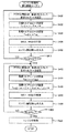
図1は、本発明の一実施形態としてのハイブリッド自動車20の構成の概略を示す構成図である。実施例のハイブリッド自動車20は、図示するように、エンジン22と、エンジン22の出力軸としてのクランクシャフト26にダンパ28を介して接続された3軸式の動力入出力機構30と、動力入出力機構30に接続された発電可能なモータMG1と、動力入出力機構30に変速機60を介して接続されたモータMG2と、エンジン22のクランクシャフト26にダンパ28を介して接続された発電可能なモータMG3と、車両の駆動系全体をコントロールするハイブリッド用電子制御ユニット70とを備える。
FIG. 1 is a configuration diagram schematically showing a configuration of a
エンジン22は、ガソリンまたは軽油などの炭化水素系の燃料により動力を出力する内燃機関であり、エンジン22の運転状態を検出する各種センサから信号を入力するエンジン用電子制御ユニット(以下、エンジンECUという)24により燃料噴射制御や点火制御,吸入空気量調節制御などの運転制御を受けている。エンジンECU24は、ハイブリッド用電子制御ユニット70と通信しており、ハイブリッド用電子制御ユニット70からの制御信号によりエンジン22を運転制御すると共に必要に応じてエンジン22の運転状態に関するデータをハイブリッド用電子制御ユニット70に出力する。
The
動力入出力機構30は、外歯歯車のサンギヤ31と、このサンギヤ31と同心円上に配置された内歯歯車のリングギヤ32と、サンギヤ31に噛合すると共にリングギヤ32に噛合する複数のピニオンギヤ33と、複数のピニオンギヤ33を自転かつ公転自在に保持するキャリア34とを備え、サンギヤ31とリングギヤ32とキャリア34とを回転要素として差動作用を行なう遊星歯車機構として構成されている。動力入出力機構30は、キャリア34にはエンジン22の出力軸およびモータMG3の回転軸をなすクランクシャフト26が、サンギヤ31にはモータMG1が、リングギヤ32には変速機60を介してモータMG2がそれぞれ連結されている。また、リングギヤ32は、デファレンシャルギヤ38を介して駆動輪39a,39bに機械的に接続されている。したがって、リングギヤ32に出力された動力は、デファレンシャルギヤ38を介して駆動輪39a,39bに出力されることになる。なお、駆動系として見たときの動力入出力機構30に接続される3軸は、キャリア34に接続されたエンジン22の出力軸およびモータMG3の回転軸となるクランクシャフト26,サンギヤ31に接続されモータMG1の回転軸となるサンギヤ軸31a,リングギヤ32に接続されると共に駆動輪39a,39bに機械的に接続された駆動軸としてのリングギヤ軸32aとなる。
The power input /
モータMG1およびモータMG2およびモータMG3は、いずれも発電機として駆動することができると共に電動機として駆動できる周知の同期発電電動機として構成されており、インバータ41,42,43を介してバッテリ50と電力のやりとりを行なう。インバータ41,42,43とバッテリ50とを接続する電力ライン54は、各インバータ41,42,43が共用する正極母線および負極母線として構成されており、モータMG1,MG2,MG3のいずれかで発電される電力を他のモータで消費することができるようになっている。したがって、バッテリ50は、モータMG1,MG2,MG3から生じた電力や不足する電力により充放電されることになる。なお、モータMG1とモータMG2とモータMG3により電力収支のバランスをとるものとすれば、バッテリ50は充放電されない。モータMG1,MG2,MG3は、いずれもモータ用電子制御ユニット(以下、モータECUという)40により駆動制御されている。モータECU40には、モータMG1,MG2,MG3を駆動制御するために必要な信号、例えばモータMG1,MG2,MG3の回転子の回転位置を検出する回転位置検出センサ44,45,46からの信号や図示しない電流センサにより検出されるモータMG1,MG2,MG3に印加される相電流などが入力されており、モータECU40からは、インバータ41,42,43へのスイッチング制御信号が出力されている。モータECU40は、回転位置検出センサ44,45,46から入力した信号に基づいて図示しない回転数算出ルーチンによりモータMG1,MG2,MG3の回転子の回転数Nm1,Nm2,Nm3を計算している。この回転数Nm1,Nm2,Nm3は、モータMG1がサンギヤ31に接続されモータMG2がリングギヤ32に接続されモータMG3がクランクシャフト26に接続されていることから、サンギヤ軸31aやリングギヤ軸32aやクランクシャフト26の回転数になる。モータECU40は、ハイブリッド用電子制御ユニット70と通信しており、ハイブリッド用電子制御ユニット70からの制御信号によってモータMG1,MG2,MG3を駆動制御すると共に必要に応じてモータMG1,MG2,MG3の運転状態に関するデータをハイブリッド用電子制御ユニット70に出力する。
Each of the motors MG1, MG2, and MG3 is configured as a known synchronous generator motor that can be driven as a generator and can be driven as a motor.
変速機60は、モータMG2の回転軸48の回転数を減速してリングギヤ軸32aに伝達できるように構成されている。この変速機60は、図1に示すように、外歯歯車のサンギヤ62とこのサンギヤ62と同心円上に配置された内歯歯車のリングギヤ64とサンギヤ62に噛合すると共にリングギヤ64に噛合する複数のピニオンギヤ66と複数のピニオンギヤ66を自転かつ公転自在に保持するキャリア68とを備えており、サンギヤ62にはモータMG2の回転軸48が接続されると共にリングギヤ64にはリングギヤ軸32aが接続され、キャリア68にはその回転が禁止されるようにモータMG2のケースに接続されている。
The
バッテリ50は、バッテリ用電子制御ユニット(以下、バッテリECUという)52によって管理されている。バッテリECU52には、バッテリ50を管理するのに必要な信号、例えば、バッテリ50の端子間に設置された図示しない電圧センサからの端子間電圧,バッテリ50の出力端子に接続された電力ライン54に取り付けられた図示しない電流センサからの充放電電流,バッテリ50に取り付けられた図示しない温度センサからの電池温度などが入力されており、必要に応じてバッテリ50の状態に関するデータを通信によりハイブリッド用電子制御ユニット70に出力する。なお、バッテリECU52では、バッテリ50を管理するために電流センサにより検出された充放電電流の積算値に基づいて残容量(SOC)も演算している。
The
ハイブリッド用電子制御ユニット70は、CPU72を中心とするマイクロプロセッサとして構成されており、CPU72の他に処理プログラムを記憶するROM74と、データを一時的に記憶するRAM76と、図示しない入出力ポートおよび通信ポートとを備える。ハイブリッド用電子制御ユニット70には、イグニッションスイッチ80からのイグニッション信号,シフトレバー81の操作位置を検出するシフトポジションセンサ82からのシフトポジションSP,アクセルペダル83の踏み込み量に対応したアクセル開度を検出するアクセルペダルポジションセンサ84からのアクセル開度AP,ブレーキペダル85の踏み込み量を検出するブレーキペダルポジションセンサ86からのブレーキペダルポジションBP,車速センサ88からの車速Vなどが入力ポートを介して入力されている。ハイブリッド用電子制御ユニット70は、前述したように、エンジンECU24やモータECU40,バッテリECU52と通信ポートを介して接続されており、エンジンECU24やモータECU40,バッテリECU52と各種制御信号やデータのやりとりを行なっている。
The hybrid
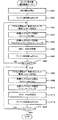
次に、こうして構成された実施例のハイブリッド自動車20の動作について説明する。図2は、実施例のハイブリッド用電子制御ユニット70により実行される運転制御ルーチンの一例を示すフローチャートである。このルーチンは、所定時間毎(例えば、8msec毎)に繰り返し実行される。
Next, the operation of the
運転制御ルーチンが実行されると、ハイブリッド用電子制御ユニット70は、まず、アクセルペダルポジションセンサ83からのアクセル開度APや車速センサ88からの車速V、バッテリECU52により演算されたバッテリ50の残容量SOCなどを入力し(ステップS100)、入力したアクセル開度APと車速Vとに基づいて駆動軸としてのリングギヤ軸32aに要求される要求トルクT*と要求動力P*とを設定する処理を行なう(ステップS102)。要求トルクT*の設定は、実施例では、アクセル開度APと車速Vと要求トルクT*との関係を予め求めて要求トルク設定マップとしてROM74に記憶しておき、アクセル開度APと車速Vとが与えられると、要求トルク設定マップから対応する要求トルクT*を導出して行なうものとし、要求動力P*の設定は、導出された要求トルクT*に車速Vから比例的に求まるリングギヤ軸32aの回転数Nr(=k・V)を乗算することにより行なうものとした。この要求トルク設定マップの一例を図3に示す。なお、リングギヤ軸32aの回転数Nrは、実施例では、車速Vから算出したものを用いるものとしたが、リングギヤ軸32aに回転数センサを設置し、この回転数センサにより直接検出したものを用いるものとしてもよい。
When the operation control routine is executed, first, the hybrid
続いて、ステップS100で入力したバッテリ50の残容量SOCに基づいてバッテリ50の充放電量Pb*を設定する(ステップS104)。このバッテリ50の充放電量Pb*の設定は、基本的には、残容量SOCが適正範囲内(例えば、60%〜70%)となるように設定することにより行われる。
Subsequently, the charge / discharge amount Pb * of the
こうして要求動力P*と充放電量Pb*とを設定すると、この要求動力P*と充放電量Pb*との和によりエンジン22が出力すべき目標動力Pe*を設定すると共に(ステップS106)、この目標動力Pe*を出力可能なエンジン22の運転ポイント(トルクと回転数とにより定まるポイント)のうちエンジン22が効率よく運転できるポイントを目標トルクTe*と目標回転数Ne*として設定し(ステップS108)、エンジン22の目標回転数Ne*と車速Vから比例的に求まるリングギヤ32の回転数Nr(=k・V)と動力入出力機構30のギヤ比ρとにより次式(1)を用いてモータMG1の目標回転数Nm1*を計算する(ステップS110)。
When the required power P * and the charge / discharge amount Pb * are set in this manner, the target power Pe * to be output by the
Nm1*=(Ne*−k・V)/ρ+Ne* …(1) Nm1 * = (Ne * −k · V) / ρ + Ne * (1)
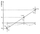
図4は、サンギヤ31の回転数Nsとリングギヤ32の回転数Nrとキャリア34の回転数Ncとの関係を示す説明図である。図4に示すように、サンギヤ31の回転数Nsとリングギア32の回転数Nrとキャリア34の回転数Ncは、次式(2)〜(4)で示すことができる。
FIG. 4 is an explanatory diagram showing a relationship among the rotation speed Ns of the
Ns=(Nc−Nr)/ρ+Nc …(2)
Nr=(1+ρ)Nc−ρNs …(3)
Nc=(Nr+ρNs)/(1+ρ) …(4)
Ns = (Nc−Nr) / ρ + Nc (2)
Nr = (1 + ρ) Nc−ρNs (3)
Nc = (Nr + ρNs) / (1 + ρ) (4)
前述したように、サンギヤ31にはモータMG1の回転軸が接続され、リングギヤ32には変速機60を介してモータMG2が接続され、キャリア34にはモータMG3と一体回転するエンジン22のクランクシャフト26が接続されているから、式(2)におけるリングギヤ32の回転数Nrを車速Vから比例的に算出し、キャリア34の回転数Ncをエンジン22の目標回転数Ne*とすれば、式(1)を用いてサンギヤ31の回転数NsであるモータMG1の目標回転数Nm1*を計算することができる。
As described above, the
こうしてモータMG1の目標回転数Nm1*を計算すると、計算した目標回転数Nm1*が負の回転数(エンジン22の回転方向を正としてエンジン22と逆方向の回転)であるか否かを判定する(ステップS112)。なお、モータMG1の回転軸はサンギヤ31に直接接続されていると共にエンジン22のクランクシャフト26はリングギヤ32に直接接続されているから、ステップS112の判定は、サンギヤ31の回転数Nsがリングギア32の回転数に対して逆方向の回転数であるか否かを判定することと同意となる。
When the target rotation speed Nm1 * of the motor MG1 is calculated in this way, it is determined whether or not the calculated target rotation speed Nm1 * is a negative rotation speed (rotation in the opposite direction to the
モータMG1の目標回転数Nm1*が負の回転数でないと判定されると、次式(5),(6),(7)を用いて各々モータMG1の目標トルクTm1*とモータMG2の目標トルクTm2*とモータMG3の目標トルクTm3*とを設定する(ステップS114)。ここで式(6)において、Rは、変速機60のギヤ比(減速比)である。
If it is determined that the target rotation speed Nm1 * of the motor MG1 is not a negative rotation speed, the target torque Tm1 * of the motor MG1 and the target torque of the motor MG2 are calculated using the following equations (5), (6) and (7). Tm2 * and target torque Tm3 * of motor MG3 are set (step S114). Here, in the equation (6), R is a gear ratio (reduction ratio) of the
Tm1*=−Te*×ρ/(1+ρ) …(5)
Tm2*=−(T*−Te*/(1+ρ))/R …(6)
Tm3*=0 …(7)
Tm1 * =-Te * × ρ / (1 + ρ) (5)
Tm2 * =-(T * -Te * / (1 + ρ)) / R (6)
Tm3 * = 0 (7)
図4に示すように、エンジン22からキャリア34に出力されるトルクTeは、サンギヤ31とリングギヤ32とに各々分配されるトルクTes(=Te×ρ/(1+ρ)),Ter(=Te×1/(1+ρ))として示すことができる。したがって、エンジン22からサンギヤ31に分配されるトルクTesに釣り合うトルク(大きさが同じで符号が反対のトルク)をモータMG1の目標トルクTm1*として設定すると共に、リングギヤ軸32a(駆動軸)の要求トルクT*とエンジン22からリングギヤ32に分配されるトルクTerとの偏差のトルク(T*−Te×1/(1+ρ))を変速機60のギヤ比Rで除算すると共に−1を乗じてモータMG2から出力すべき目標トルクTm2*として設定すれば、エンジン22から出力されるトルクTeを変換してリングギヤ軸32aに要求トルクT*を出力することができる。このとき、モータMG1はトルクと回転数とが逆方向の回生運転となり、モータMG2はトルクと回転数とが同方向の力行運転となるから、実施例のハイブリッド自動車20はエンジン22から出力された動力を用いてモータMG1で回生されると共に回生電力を用いてモータMG2で力行されて動力が駆動軸に出力される形態となる。したがって、モータMG2の力行により出力される動力の一部がモータMG1で回生されることがないから、エネルギ循環は生じない。なお、モータMG2の目標トルクTm2*を設定する際に、式(6)の右辺で−1を乗じているのは、変速機60によりモータMG2の回転方向とリングギヤ32の回転方向とが逆になることに基づいている。
As shown in FIG. 4, the torque Te output from the
一方、モータMG1の目標回転数Nm1*が負の回転数であると判定されると、次式(8),(9),(10)を用いて各々モータMG1の目標トルクTm1*とモータMG2の目標トルクTm2*とモータMG3の目標トルクTm3*とを設定する(ステップS116)。このときのサンギヤ31とリングギヤ32とキャリア34の回転数とトルクの関係を図5に示す。
On the other hand, if it is determined that the target rotation speed Nm1 * of the motor MG1 is a negative rotation speed, the target torque Tm1 * of the motor MG1 and the motor MG2 are calculated using the following equations (8), (9), and (10). The target torque Tm2 * of the motor MG3 and the target torque Tm3 * of the motor MG3 are set (step S116). FIG. 5 shows the relationship between the rotational speed and the torque of the
Tm1*=−ρ×T* …(8)
Tm2*=0 …(9)
Tm3*=T*×(1+ρ)−Te* …(10)
Tm1 * = − ρ × T * (8)
Tm2 * = 0 (9)
Tm3 * = T * × (1 + ρ) −Te * (10)
モータMG1の目標回転数Nm1*が負の回転数のときにステップS114における式(5)と式(6)を用いてモータMG1の目標トルクTm1*とモータMG2の目標トルクTm2*とを設定すると、図5に示すように、モータMG1はトルクと回転数が同一方向の力行運転となる。一方、エンジン22からキャリア34を介してリングギヤ32に分配されるトルクTerは要求トルクT*よりも大きくなるためモータMG2から出力すべきトルク(目標トルクTm2*)は回転数と逆方向のトルクとなり、モータMG2は回生運転となる。この状態は、モータMG1の力行により出力された動力の一部がモータMG2で回生される状態であるから、エネルギ循環が生じる。そこで、図5に示すように、モータMG2における回生運転の代わりにエンジン22のクランクシャフト26に接続されたモータMG3を用いて、エンジン22からキャリア34を介してリングギヤ32に分配されるトルクTerとクランクシャフト26に接続されたモータMG3からキャリア34を介してリングギヤ32に分配されるトルクTmrとの差が要求トルクT*となるようモータMG3を回生運転すれば、エンジン22から出力された動力を用いてモータMG3で回生されると共に回生電力を用いてモータMG1で力行されて動力が駆動軸に出力される形態となり、モータMG1の力行で出力される動力の一部がモータMG3で回生されることがないから、エネルギ循環は生じない。この結果、全体のエネルギ効率をより向上させることができるのである。なお、モータMG1の目標トルクTm1*は、式(8)に示すように、エンジン22からキャリア34を介してサンギヤ31に分配されるトルクTesとクランクシャフト26に接続されたモータMG3からキャリア34を介してサンギヤ31に分配されるトルクTmsとの差に対して釣り合いがとれるよう設定すればよい。
When the target rotation speed Nm1 * of the motor MG1 is a negative rotation speed, the target torque Tm1 * of the motor MG1 and the target torque Tm2 * of the motor MG2 are set using the equations (5) and (6) in step S114. As shown in FIG. 5, the motor MG1 performs a power running operation in which the torque and the rotation speed are in the same direction. On the other hand, since the torque Ter distributed from the
こうしてエンジン22の目標トルクTe*と、モータMG1の目標回転数Nm1*および目標トルクTm1*と、モータMG2の目標トルクTm2*と、モータMG3の目標トルクTm3*とが設定されると、目標トルクTe*でエンジン22を運転制御すると共に目標回転数Nm1*および目標トルクTm1*でモータMG1を運転制御し、目標トルクTm2*でモータMG2を運転制御し、目標トルクTm3*でモータMG3を運転制御して(ステップS118)、本ルーチンを終了する。エンジン22やモータMG1,MG2,MG3の運転制御は、具体的には、ハイブリッド用電子制御ユニット70が目標トルクTe*をエンジンECU24に出力することによりエンジンECU24が目標トルクTe*に見合うトルクがエンジン22から出力されるようエンジン22を制御することにより行なわれ、ハイブリッド用電子制御ユニット70が目標トルクTm1*,目標回転数Nm1*,目標トルクTm2*,目標トルクTm3*をモータECU40に出力することによりモータECU40が、目標トルクTm1*,目標回転数Nm1*でモータMG1が運転されるようモータMG1を制御すると共に目標トルクTm2*に見合うトルクがモータMG2から出力されるようモータMG2を制御し、目標トルクTm3*に見合うトルクがモータMG3から出力されるようモータMG3を制御することにより行なわれる。
When the target torque Te * of the
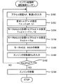
次に、停止していたエンジン22を始動する際のハイブリッド自動車120の動作について説明する。図6は、実施例のハイブリッド自動車20のハイブリッド用電子制御ユニット70により実行されるエンジン始動時運転制御ルーチンの一例を示すフローチャートである。このルーチンは、エンジン22が停止している状態で運転者がエンジン22の始動を指示するスイッチをオン操作したときや、エンジン22が停止している状態でモータMG2の駆動により走行しているときに車速Vが所定車速以上となったり要求動力P*が所定動力以上となったとき、エンジン22が停止している状態でバッテリ50の残容量SOCが所定量未満となったときなどに実行される。
Next, the operation of the
エンジン始動時運転制御ルーチンが実行されると、ハイブリッド用電子制御ユニット70のCPU72は、まず、アクセル開度APや車速Vなどを入力し(ステップS150)、入力したアクセル開度APと車速Vとに基づいて前述の図3の要求トルク設定マップを用いて駆動軸としてのリングギヤ軸32aに要求される要求トルクT*を設定し(ステップS152)、設定した要求トルクT*を変速機60のギヤ比Rで除算すると共に−1を乗じてモータMG2が出力すべき目標トルクTm2*を設定する(ステップS154)。
When the engine start operation control routine is executed, the
そして、エンジン22のクランクシャフト26に接続されたモータMG3を用いてエンジン22をモータリングするために、モータMG3の目標トルクTm3*としてスタータトルクTstを設定する(ステップS156)。
Then, in order to motor the
こうしてモータMG2の目標トルクTm2*とモータMG3の目標トルクTm3*とを設定すると、設定された目標トルクTm2*と目標トルクTm3*でモータMG2とモータMG3とを各々制御する(ステップS158)。このとき、モータMG1は、動力入出力機構30を介してリングギヤ軸32a(駆動軸)にトルクが出力されないよう目標トルクTm1*(例えば、値0)が設定されて制御されることになる。
When the target torque Tm2 * of the motor MG2 and the target torque Tm3 * of the motor MG3 are set in this way, the motor MG2 and the motor MG3 are respectively controlled by the set target torque Tm2 * and target torque Tm3 * (step S158). At this time, the target torque Tm1 * (for example, value 0) of the motor MG1 is controlled such that no torque is output to the
次に、エンジン22の回転数Neを入力し(ステップS160)、入力したエンジン22の回転数Neがエンジン22を連続運転できる回転数Nstに達したときに(ステップS162)、燃料噴射制御や点火制御などのエンジン22を始動させる処理を行って(ステップS164)、本ルーチンを終了する。なお、エンジン22の回転数Neが回転数Nstに達していないときには、ステップS150の処理に戻る。これにより、モータMG2の駆動によりハイブリッド自動車20を走行させることができると共にモータMG3の駆動により停止しているエンジン22をモータリングさせて始動させることができる。また、モータMG1の駆動によりエンジン22をモータリングすることもできるが、モータMG1を駆動するとその駆動に応じたトルクが反力としてリングギヤ軸32aに作用することになるから、モータMG3を駆動することにより、トルクショックがリングギヤ軸32aに作用するのを抑制しながらエンジン22をスムーズに始動させることができる。
Next, the engine speed Ne of the
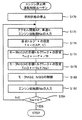
次に、エンジン22を停止させる際の実施例のハイブリッド自動車20の動作について説明する。図7は、実施例のハイブリッド自動車20のハイブリッド用電子制御ユニット70により実行されるエンジン停止時運転制御ルーチンの一例を示すフローチャートである。このルーチンは、エンジン22の停止が指示されたときに実行される。
Next, an operation of the
エンジン停止時運転制御ルーチンが実行されると、ハイブリッド用電子制御ユニット70のCPU72は、まず、エンジン22への燃料供給を停止して(ステップS170)、アクセル開度APと車速Vとエンジン回転数Neとを入力し(ステップS172)、入力したアクセル開度APと車速Vとに基づいて前述した図3の要求トルク設定用マップを用いて要求トルクT*を設定する(ステップS174)。続いて、設定した要求トルクT*がリングギヤ軸32aに出力されるよう要求トルクT*に変速機60の変速比Rを除した値に−1を乗じることによりモータMG2の目標トルクTm2*を設定すると共に(ステップS176)、エンジン22の回転を停止させるよう入力したエンジン回転数Neに基づいてモータMG3から出力すべき目標トルクTm3*を設定して(ステップS178)、モータMG2,MG3を駆動制御する(ステップS180)。なお、モータMG1は、トルクが出力されないよう値0の目標トルクTm1*で制御されることになる。
When the engine stop operation control routine is executed, the
こうしてモータMG2,MG3を駆動制御すると、次に、エンジン回転数Neを入力し(ステップS182)、入力したエンジン回転数Neが値0、即ち、エンジン22の回転が停止するまでステップS172に戻ってステップS172〜S180の処理を繰り返し、エンジン回転数Neが値0に至ったときに(ステップS184)、本ルーチンを終了する。これにより、モータMG2からのトルクの出力により目標トルクT*に見合うトルクでハイブリッド自動車20を走行させることができると共にモータMG3によりエンジン22の回転を停止させることができる。また、モータMG1によりエンジン22の回転を停止させることもできるが、モータMG1によるとその駆動に応じたトルク反力がリングギヤ軸32aに作用することになり、トルクショックが生じる。モータMG3によりエンジン22の回転を停止させることにより、こうしたトルク反力がリングギヤ軸32aに作用することがないから、トルクショックを抑制しながらエンジン22の回転をスムーズに停止させることができる。
When the drive of the motors MG2 and MG3 is controlled in this manner, the engine speed Ne is input (step S182), and the process returns to step S172 until the input engine speed Ne is the
以上説明した実施例のハイブリッド自動車20によれば、モータMG1の回転が負回転となるときには、モータMG1で回生した電力がモータMG2に供給される形態でエンジン22からの動力をモータMG1とモータMG2とでトルク変換して要求動力P*がリングギヤ軸32a(駆動軸)へ出力されるようエンジン22とモータMG1,MG2,MG3とを運転制御し、モータMG1の回転が負回転とならないときには、モータMG3で回生した電力がモータMG1に供給される形態でエンジン22からの動力をモータMG3とモータMG1とでトルク変換して要求動力P*がリングギヤ軸32aに出力されるようエンジン22とモータMG1,MG2,MG3とを運転制御するから、モータMG1の回転の状態に拘わらずエネルギ循環が生じるのを回避でき、自動車全体のエネルギ効率をより向上させることができる。
According to the
また、実施例のハイブリッド自動車20によれば、エンジン22を始動する際や停止する際には、エンジン22のクランクシャフト26に一体的に接続されたモータMG3の駆動によりエンジン22をモータリングして始動したりエンジン22を制動したりするから、エンジン22の始動の際や停止の際にリングギヤ軸32a(駆動軸)にトルクショックが生じるのを抑制できる。
Further, according to the
また、実施例のハイブリッド自動車20によれば、エンジン22のクランクシャフト26と一体的に回転するようモータMG3を接続したから、エンジン22とモータMG3との間の伝達効率を向上させることができる。
According to the
実施例のハイブリッド自動車20では、エンジン22からモータMG3,モータMG1,モータMG2の順にモータMG1,MG2,MG3を配置するものとしたが、図8の変形例のハイブリッド自動車に示すように、エンジン22からモータMG3,モータMG2,モータMG1の順にモータMG1,MG2,MG3を配置するものとしてもよい。なお、図8の例では、動力入出力機構30のリングギア軸32aは、ギヤ機構37,ディファレンシャルギヤ38を介して駆動輪39a,39bに接続されている。
In the
実施例のハイブリッド自動車20では、モータMG3は、エンジン22のクランクシャフト26に一体的に接続するものとしたが、これに限られず、図9および図10の変形例のハイブリッド自動車に示すように、モータMG3の回転軸92をエンジン22のクランクシャフト26の一端とベルト90を介して接続するものとしてもよいし、図示しないギヤやチェーンを介して接続するものとしてもよい。こうすれば、自動車の空きスペースにモータMG3を搭載することも可能となり、自動車の小型化を図ることができる。なお、図9の例では、モータMG1とモータMG2とを、エンジン22からモータMG1,モータMG2の順に配置し、図10の例では、モータMG1とモータMG2とを、エンジン22からモータMG2,モータMG1の順に配置している。
In the
次に、モータMG1から出力可能な負のトルクの下限(トルク下限値Tm1min)の範囲内でモータMG1を制御する際のハイブリッド自動車20の動作について説明する。図11は、実施例のハイブリッド自動車20のハイブリッド用電子制御ユニット70により実行される第2運転制御ルーチンの一例を示すフローチャートである。このルーチンは、所定時間毎(例えば、8msec毎)に繰り返し実行される。
Next, the operation of
第2運転制御ルーチンが実行されると、ハイブリッド用電子制御ユニット70のCPU72は、まず、アクセル開度APや車速V,残容量SOCなどを入力し(ステップS300)、入力したアクセル開度APと車速Vとに基づいて前述した図3の要求トルク設定用マップを用いてリングギヤ軸32aに出力すべき要求トルクT*を設定すると共に要求トルクT*にリングギヤ軸32aの回転数Nr(=k・V)を乗じて要求動力P*を設定する(ステップS302)。続いて、残容量SOCに基づいてバッテリ50が充放電すべきバッテリ充放電量Pb*を設定し(ステップS304)、設定した要求動力P*とバッテリ充放電量Pb*とを加算してエンジン22から出力すべき目標動力Pe*を設定し(ステップS306)、設定した目標動力Pe*を出力可能な運転ポイントのうちエンジン22が最も効率よく運転できるトルクと回転数とをエンジン22の目標トルクTe*と目標回転数Ne*として設定する(ステップS308)。
When the second operation control routine is executed, first, the
次に、モータMG1のトルク下限値Tm1minに基づいて次式(11)により閾値Temaxを設定する(ステップS310)。ここで、閾値Temaxは、エンジン22から出力されるトルクの反力をモータMG1だけで受け持つことのできるトルクの上限として設定されるものである。
Next, based on the torque lower limit value Tm1min of the motor MG1, a threshold value Temax is set by the following equation (11) (step S310). Here, the threshold Temax is set as an upper limit of the torque that can be used for the reaction force of the torque output from the
Temax=−Tm1min・(1+ρ)/ρ …(11) Temax = −Tm1min · (1 + ρ) / ρ (11)
閾値Temaxを設定すると、ステップS308で設定されたエンジン22の目標トルクTe*が閾値Temaxよりも大きいか否かを判定し(ステップS312)、目標トルクTe*が閾値Temaxよりも大きくないと判定されると、エンジン22から出力されるトルクの反力はモータMG1のトルク下限値Tm1minの範囲内で受け持つことができると判断して、前述した式(5)〜(7)によりモータMG1,MG2,MG3の目標トルクTm1*,Tm2*,Tm3*を設定し(ステップS314)、目標トルクTe*でエンジン22を駆動制御すると共に目標トルクTm1*,Tm2*,Tm3*でモータMG1,MG2,MG3を駆動制御する処理を行なって(ステップS318)、本ルーチンを終了する。
When the threshold Temax is set, it is determined whether the target torque Te * of the
一方、目標トルクTe*が閾値Temaxよりも大きいと判定されると、エンジン22から出力されるトルクの反力はモータMG1のトルク下限値Tm1minの範囲内で受け持つことができないと判断して、モータMG1とモータMG3とによりエンジン22から出力されるトルクの反力を分担してモータMG1のトルク下限値Tm1minの範囲を越えないよう次式(12)〜(14)によりモータMG1,MG2,MG3の目標トルクTm1*,Tm2*,Tm3*を設定し(ステップS316)、目標トルクTe*でエンジン22を駆動制御すると共に目標トルクTm1*,Tm2*,Tm3*でモータMG1,MG2,MG3を駆動制御する処理を行なって(ステップS318)、本ルーチンを終了する。
On the other hand, if it is determined that the target torque Te * is greater than the threshold Temax, it is determined that the reaction force of the torque output from the
Tm1*=Tm1min …(12)
Tm2*=−(T*+Tm1min/ρ)/R …(13)
Tm3*=−Te*−Tm1min・(1+ρ)/ρ …(14)
Tm1 * = Tm1min (12)
Tm2 * =-(T * + Tm1min / ρ) / R (13)
Tm3 * = − Te * −Tm1min · (1 + ρ) / ρ (14)
図12に、目標トルクTe*が閾値Temaxよりも大きいときの動力入出力機構30の各回転要素の回転数とトルクの力学的な関係を示す。図示するように、モータMG1の目標トルクTm1*は、エンジン22から出力されるトルク(目標トルクTe*)にエンジン22のクランクシャフト26に接続されたモータMG3から出力される負のトルク(目標トルクTm3*)との和のトルクによりサンギヤ31に作用するトルクTesと釣り合うように設定すればよい。したがって、目標トルクTe*と閾値Temaxとの偏差のトルクをモータMG3から出力すれば、モータMG1の目標トルクTm1*をトルク下限値Tm1minの範囲内に収めることができる。なお、モータMG2の目標トルクTm2*は、要求トルクT*からエンジン22から出力されるトルク(目標トルクTe*)にエンジン22のクランクシャフト26に接続されたモータMG3から出力される負のトルク(目標トルクTm3*)との和のトルクによりリングギヤ32に作用するトルクTerを減じて変速機60の変速比Rを除したものに値1を乗じることにより設定することができる。
FIG. 12 shows a dynamic relationship between the rotational speed of each rotating element of the power input /
以上説明した実施例のハイブリッド自動車20によれば、モータMG1のトルク下限値Tm1minの範囲内でモータMG1を運転しながら要求トルクT*をリングギヤ軸32aに出力して走行することができる。この結果、モータMG1の体格を小さくすることができ、装置全体を小型化することができる。
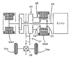
According to the
次に、第2実施例のハイブリッド自動車120について説明する。図13は、第2実施例のハイブリッド自動車120の構成の概略を示す構成図である。第2実施例のハイブリッド自動車120は、エンジン22のクランクシャフト26に接続されたモータMG3を備えない点と、モータMG2の回転軸48とエンジン22のクランクシャフト26とを機械的に接続したり接続解除したりすることができるクラッチC1および変速機60を介してモータMG2の回転軸48と動力入出力機構30のリングギヤ軸32aとを機械的に接続したり接続解除したりすることができるクラッチC2を備える点と、ハイブリッド用電子制御ユニット70の処理とが実施例のハイブリッド自動車20と異なる。したがって、第2実施例のハイブリッド自動車120のうち実施例のハイブリッド自動車20と同一の構成については同一の符号を付すと共に一部についてはその図示を省略した。なお、図13において、クラッチC1,C2は、例えば、油圧により駆動できるように構成されている。また、リングギヤ軸32aは、ギヤ機構37とディファレンシャルギヤ38を介して駆動輪39a,39bに接続されている。
Next, a
第2実施例のハイブリッド自動車120が備えるハイブリッド用電子制御ユニット70は、実施例のハイブリッド自動車20と同様にCPU72やROM74,RAM76,入出力ポートを備えており、ハイブリッド用電子制御ユニット70からはクラッチC1やクラッチC2への駆動信号が出力ポートを介して出力されている。以下、こうして構成された第2実施例のハイブリッド自動車120の動作について説明する。
The hybrid
図14は、第2実施例のハイブリッド自動車120のハイブリッド用電子制御ユニット70により実行される運転制御ルーチンの一例を示すフローチャートである。このルーチンは、所定時間毎(例えば、8msec毎)に繰り返し実行される。運転制御ルーチンが実行されると、ハイブリッド用電子制御ユニット70のCPU72は、まず、図2の運転制御ルーチンのステップS100〜S110と同様の処理、すなわちアクセル開度APや車速V、残容量SOCなどを入力し(ステップS200)、入力したアクセル開度APと車速Vとに基づいて駆動軸としてのリングギヤ軸32aに要求される要求トルクT*と要求動力P*とを設定すると共に(ステップS202)、バッテリ50の充放電量Pb*を設定して(ステップS204)、設定された要求動力P*と充放電量Pb*との和によりエンジン22が出力すべき目標動力Pe*を設定する(ステップS206)。続いて、この目標動力Pe*を出力可能なエンジン22の運転ポイントのうち効率よく運転できるポイントをエンジン22の目標トルクTe*と目標回転数Ne*として設定し(ステップS208)、エンジン22の目標回転数Ne*と車速Vから比例的に求まるリングギヤ32の回転数Nr(=k・V)と動力入出力機構30のギヤ比ρとにより前述の式(1)を用いてモータMG1の目標回転数Nm1*を計算する(ステップS210)。
FIG. 14 is a flowchart illustrating an example of an operation control routine executed by the hybrid
モータMG1の目標回転数Nm1*が計算されると、モータMG1の目標回転数Nm1*が負の回転数(エンジン22の回転方向を正としてエンジン22と逆方向の回転)であるか否かを判定し(ステップS212)、目標回転数Nm1*が負の回転数でないと判定されたときには、クラッチC1がオフでクラッチC2がオンされるようにクラッチC1とクラッチC2とを駆動して(ステップS214,S216)、前述の式(5),(6)を用いてモータMG1の目標トルクTm1*とモータMG2の目標トルクTm2*とを各々設定する(ステップS218)。クラッチC1がオフでクラッチC2がオンの状態は、モータMG2の回転軸48が変速機60を介してリングギヤ軸32aに接続されている状態であるから、実施例のハイブリッド自動車20のモータMG3を備えない状態と同一の状態となる。したがって、式(5),(6)を用いてモータMG1,MG2の目標トルクTm1*,Tm2*を設定すれば、実施例のハイブリッド自動車20はエンジン22からの動力を用いてモータMG1で回生されると共に回生電力を用いてモータMG2で力行されて動力が駆動軸に出力される形態となり、モータMG2の力行により出力された動力の一部がモータMG1で回生されることがないから、エネルギ循環は生じない。
When the target rotation speed Nm1 * of the motor MG1 is calculated, it is determined whether or not the target rotation speed Nm1 * of the motor MG1 is a negative rotation speed (rotation in a direction opposite to the
一方、モータMG1の目標回転数Nm1*が負の回転数であると判定されたときには、クラッチC1がオンでクラッチC2がオフされるようにクラッチC1とクラッチC2とを駆動して(ステップS220,S222)、前述の式(8)を用いてモータMG1の目標トルクTm1*を設定すると共に前述の式(10)を変更した次式(15)を用いてモータMG2の目標トルクTm2*を設定する(ステップS224)。ここで、Rは、変速機60のギヤ比(減速比)である。
On the other hand, when it is determined that the target rotation speed Nm1 * of the motor MG1 is a negative rotation speed, the clutch C1 and the clutch C2 are driven such that the clutch C1 is on and the clutch C2 is off (step S220, S222), the target torque Tm1 * of the motor MG1 is set using the above equation (8), and the target torque Tm2 * of the motor MG2 is set using the following equation (15) obtained by modifying the above equation (10). (Step S224). Here, R is a gear ratio (reduction ratio) of the
Tm2*=−(T*×(1+ρ)−Te*)/R …(15) Tm2 * =-(T * (1 + ρ) -Te *) / R (15)
クラッチC1がオンでクラッチC2がオフの状態は、モータMG2の回転軸48が変速機60を介してエンジン22のクランクシャフト26に接続されている状態であるから、式(8)を用いてモータMG1の目標トルクTm1*を設定すると共に式(10)の右辺に変速機60のギヤ比Rを除算すると共に−1を乗じた式(15)を用いてモータMG2の目標トルクTm2*を設定すれば、実施例のハイブリッド自動車20はエンジン22からの動力を用いてモータMG2で回生されると共に回生電力を用いてモータMG1で力行されて駆動軸に出力される形態となる。したがって、モータMG1の力行により出力された動力の一部がモータMG2で回生されることがないから、エネルギ循環は生じない。なお、式(15)において、−1を乗じるのは、変速機60によりモータMG2の回転とエンジン22のクランクシャフト26の回転とが逆方向になることに基づいている。
The state in which the clutch C1 is on and the clutch C2 is off is a state in which the
こうしてエンジン22の目標トルクTe*とモータMG1の目標回転数Nm1*,目標トルクTm1*とモータMG2の目標トルクTm2*とが設定されると、目標トルクTe*でエンジン22を運転制御すると共に目標回転数Nm1*,目標トルクTm1*でモータMG1を運転制御し、目標トルクTm2*でモータMG2を運転制御して(ステップS226)、本ルーチンを終了する。
When the target torque Te * of the
次に、停止しているエンジン22を始動する際の第2実施例のハイブリッド自動車120の動作について説明する。図15は、第2実施例のハイブリッド自動車120のハイブリッド用電子制御ユニット70により実行されるエンジン始動時運転制御ルーチンの一例を示すフローチャートである。このルーチンは、停車時にエンジン22の始動が指示されたとき、例えば、エンジン22の始動を指示するスイッチがオン操作されたときに実行される。
Next, the operation of the
エンジン始動時運転制御ルーチンが実行されると、ハイブリッド用電子制御ユニット70のCPU72は、まず、クラッチC1がオンでクラッチC2がオフされるようクラッチC1とクラッチC2とを駆動する(ステップS250,S252)。クラッチC1をオンすると共にクラッチC2をオフすると、モータMG2の回転軸48が変速機60を介してエンジン22のクランクシャフト26に接続された状態となる。続いて、モータMG2の目標トルクTm2*をエンジン22をモータリングできるスタータトルクTstに設定して(ステップS254)、モータMG2を運転制御する(ステップS256)。なお、モータMG1は、トルクが出力されないように値0の目標トルクTm1*が設定されて駆動制御されることになる。したがって、モータMG2のトルク反力はリングギヤ軸32aに作用しない。
When the engine start operation control routine is executed, the
そして、エンジン22の回転数Neを入力して(ステップS258)、入力した回転数Neがエンジン22を連続運転できる回転数Nstに達したときに(ステップS260)、燃料噴射制御や点火制御などのエンジン22を始動させる処理を行って(ステップS262)、本ルーチンを終了する。これにより、停車時にモータMG2によりエンジン22をモータリングして始動することができる。また、クラッチC1をオンとすると共にクラッチC2をオフとしたときにトルク反力がリングギヤ軸32aに作用しないモータMG2によりエンジン22をモータリングして始動するから、トルク反力がリングギヤ軸32aに作用するモータMG1によってエンジン22をモータリングする場合に比してリングギヤ軸32aのトルクショックを抑制でき、エンジン22をスムーズに始動することができる。
Then, the engine speed Ne of the
次に、エンジン22を停止する際の第2実施例のハイブリッド自動車120の動作について説明する。図16は、第2実施例のハイブリッド自動車120のハイブリッド用電子制御ユニット70により実行されるエンジン停止時運転制御ルーチンの一例を示すフローチャートである。このルーチンは、停車中にエンジン22の停止が指示されたときに実行される。
Next, the operation of the
エンジン停止時運転制御ルーチンが実行されると、ハイブリッド用電子制御ユニット70のCPU72は、まず、クラッチC1がオンされるようクラッチC1を駆動制御すると共に(ステップS270)、クラッチC2がオフされるようクラッチC2を駆動制御する(ステップS272)。これにより、モータMG2の回転軸48が変速機60を介してエンジン22のクランクシャフト26に接続された状態となる。クラッチC1,C2を駆動制御すると、エンジン22への燃料供給を停止して(ステップS274)、エンジン回転数Neを入力し(ステップS276)、エンジン22の回転を停止させるよう入力したエンジン回転数Neに基づいてモータMG2の目標トルクTm2*を設定して(ステップS278)、モータMG2を駆動制御する(ステップS280)。このとき、モータMG1は、トルクが出力されないよう値0の目標トルクTm1*で駆動制御される。したがって、モータMG2のトルク反力はリングギヤ軸32aには作用しない。
When the engine stop operation control routine is executed, the
モータMG2を駆動制御すると、エンジン回転数Neを入力して(ステップS282)、エンジン回転数Neが値0、即ち、エンジン22の回転が停止するまでステップS278に戻ってステップS278〜S282の処理を繰り返し、エンジン回転数Neが値0に至ったときに(ステップS284)、本ルーチンを終了する。これにより、停車時にモータMG3によりエンジン22の回転を停止させることができる。また、クラッチC1をオンとすると共にクラッチC2をオフとしたときにトルク反力がリングギヤ軸32aに作用しないモータMG2によりエンジン22をモータリングして始動するから、トルク反力がリングギヤ軸32aに作用するモータMG1によってエンジン22をモータリングする場合に比してリングギヤ軸32aのトルクショックを抑制でき、エンジン22をスムーズに停止することができる。
When the drive of the motor MG2 is controlled, the engine speed Ne is input (step S282), and the process returns to step S278 until the engine speed Ne is 0, that is, the rotation of the
以上説明した第2実施例のハイブリッド自動車120においても、実施例のハイブリッド自動車20と同様の効果、即ちモータMG1の回転の状態に拘わらずエネルギ循環が生じるのを回避でき、自動車全体のエネルギ効率をより向上させることができるという効果を奏することができる。
Also in the
第2実施例のハイブリッド自動車120によれば、エンジン22を始動する際や停止する際には、モータMG2の回転軸48とエンジン22のクランクシャフト26とを接続状態として、モータMG2を用いてエンジン22をモータリングして始動したりエンジン22の回転を停止させるから、エンジン22の始動の際や停止の際にリングギヤ軸32a(駆動軸)にトルクショックが生じるのを抑制することができる。
According to the
第2実施例のハイブリッド自動車120では、エンジン22からモータMG1,モータMG2の順にモータMG1,MG2を配置するものとしたが、図17に例示する変形例のハイブリッド自動車に示すように、エンジンからモータMG2,モータMG1の順にモータMG1,MG2を配置するものとしてもよい。
In the
次に、第3実施例のハイブリッド自動車220について説明する。図18は、第3実施例のハイブリッド自動車220の構成の概略を示す構成図である。第3実施例のハイブリッド自動車220は、図示するように、ダンパ228の外周にモータMG3を取り付けた点を除いて実施例のハイブリッド自動車20と同一のハード構成を備える。したがって、第3実施例のハイブリッド自動車220のうち実施例のハイブリッド自動車20と同一の構成については同一の符号を付してその説明は省略する。ダンパ228は、エンジン22のクランクシャフト26に取り付けられたアウター部材228aと、動力入出力機構30のキャリア34に取り付けられたインナー部材228bと、アウター部材228aとインナー部材228bとの間に設けられたダンパーバネ228cとにより構成されている。モータMG3は、モータMG1に比して低トルク型の同期発電電動機として構成されており、アウター部材228aの外周にダンパ228の軸と同軸の同心円上に取り付けられている。したがって、モータMG3は、ダンパーバネ228cを介さずにエンジン22のクランクシャフト26に動力を入出力することができる。なお、第3実施例のハイブリッド自動車220では、図示するように、エンジン22とモータMG1,MG2,MG3と動力入出力機構30と変速機60は、同軸上に配置されている。
Next, a description will be given of a
こうして構成された第3実施例のハイブリッド自動車220の動作、特に、エンジン22を始動させる際の動作とエンジン22を停止させる際の動作について説明する。まず、エンジン22を始動させる際の動作について説明する。図19は、第3実施例のハイブリッド自動車220のハイブリッド用電子制御ユニット70により実行されるエンジン始動時運転制御ルーチンの一例を示すフローチャートである。このルーチンは、エンジン22の始動が指示されたときに実行される。
The operation of the
エンジン始動時運転制御ルーチンが実行されると、ハイブリッド用電子制御ユニット70のCPU72は、まず、アクセル開度APと車速Vなどを入力してリングギヤ軸32aへの要求トルクT*を設定し(ステップS400)、設定した要求トルクT*から変速機60のギヤ比Rを除したものに−1を乗じてモータMG2から出力すべき目標トルクTm2*に設定すると共に(ステップS402)、ダンパ228を介さずにエンジン22のクランクシャフト26に接続されたモータMG3を用いてエンジン22をモータリングするためのスタータトルクTstをモータMG3の目標トルクTm3*として設定して(ステップS404)、設定した目標トルクTm2*,Tm3*によりモータMG2,MG3を駆動制御する(ステップS406)。このとき、モータMG1は、トルクが出力されないよう値0の目標トルクTm1*で駆動制御されることになる。これにより、モータMG3のトルク反力はリングギヤ軸32aに作用しない。
When the engine start operation control routine is executed, the
モータMG2,MG3を駆動制御すると、エンジン回転数Neを入力し(ステップS408)、入力したエンジン回転数Neが閾値Nref以上となるまでステップS400に戻ってステップS400〜S408の処理を繰り返し、エンジン回転数Neが閾値Nref以上となったときに(ステップS410)、次の処理に進む。ここで、閾値Nrefは、ダンパ228を介してエンジン22のクランクシャフト26に接続されたモータMG1によりエンジン22をモータリングしたときにエンジン22とダンパ228とモータMG1とからなる系にねじりによる共振現象が生じうる回転数の領域の上限値よりも高い回転数として設定されている。即ち、エンジン回転数Neが共振現象が生じうる回転数の領域を通過するまではダンパ228を含む系における共振現象の発生を抑制するためにダンパ228を介さずにエンジン22のクランクシャフト26に接続されたモータMG3を用いてエンジン22をモータリングするのである。
When the driving of the motors MG2 and MG3 is controlled, the engine speed Ne is input (step S408), and the process returns to step S400 until the input engine speed Ne becomes equal to or more than the threshold value Nref, and the processes of steps S400 to S408 are repeated. When the number Ne becomes equal to or larger than the threshold value Nref (step S410), the process proceeds to the next process. Here, the threshold value Nref is a resonance phenomenon caused by torsion in a system including the
エンジン回転数Neが閾値Nref以上となると、アクセル開度APと車速Vとを入力して要求トルクT*を設定し(ステップS412)、エンジン22をモータリングするためのスタータトルクTstをモータMG3に代えてモータMG1により受け持つようモータMG1の目標トルクTm1*を設定すると共に(ステップS414)、モータMG1のトルク反力をキャンセルしながら要求トルクT*がリングギヤ軸32aに出力されるよう次式(16)によりモータMG2の目標トルクTm2*を設定し(ステップS416)、設定した目標トルクTm1*,Tm2*でモータMG1,MG2を駆動制御する(ステップS418)。このとき、モータMG3は、トルクが出力されないよう値0の目標トルクTm3*で駆動制御されることになる。
When the engine speed Ne becomes equal to or greater than the threshold value Nref, the accelerator opening AP and the vehicle speed V are input to set a required torque T * (step S412), and a starter torque Tst for motoring the
Tm2*=(T*+Tm1*/ρ)/R …(16) Tm2 * = (T * + Tm1 * / ρ) / R (16)
モータMG1,MG2を駆動制御すると、エンジン回転数Neを入力し(ステップS420)、入力したエンジン回転数Neが回転数Nstに達するまでステップS412に戻ってステップS412〜S420の処理を繰り返し、エンジン回転数Neが回転数Nstに達したときに(ステップS422)、燃料噴射制御や点火制御を開始することによりエンジン22を始動して(ステップS424)、本ルーチンを終了する。これにより、リングギヤ軸32aに要求トルクT*を出力しながらエンジン22を始動できる。また、エンジン22の初爆の際にサンギヤ31に作用する比較的大きなトルクをモータMG3よりも高トルクを入出力可能なモータMG1により受け持つことができる。
When the drive of the motors MG1 and MG2 is controlled, the engine speed Ne is input (step S420), and the process returns to step S412 until the input engine speed Ne reaches the engine speed Nst, and the processes of steps S412 to S420 are repeated. When the number Ne reaches the rotation speed Nst (step S422), the
次に、エンジン22を停止する際の動作について説明する。図20は、第3実施例のハイブリッド自動車220のハイブリッド用電子制御ユニット70により実行されるエンジン停止時運転制御ルーチンの一例を示すフローチャートである。このルーチンは、エンジン22の停止が指示されたときに実行される。
Next, an operation when the
エンジン停止時運転制御ルーチンが実行されると、ハイブリッド用電子制御ユニット70のCPU72は、まず、エンジン22の燃料噴射を停止して(ステップS450)、エンジン回転数Neを入力する(ステップS452)。続いて、アクセル開度APと車速Vとを入力してリングギヤ軸32aへの要求トルクT*を設定し(ステップS454)、エンジン22の回転を強制的に低下させるよう入力したエンジン回転数Neに基づいてモータMG1の目標トルクTm1*を設定すると共に(ステップS456)、モータMG1のトルク反力をキャンセルしながら要求トルクT*がリングギヤ軸32aに出力されるよう前述した式(16)によりモータMG2の目標トルクTm2*を設定して(ステップS458)、モータMG1,MG2を駆動制御する(ステップS460)。このとき、モータMG3は、トルクが出力されないよう値0の目標トルクTm3*で駆動制御されることになる。燃料噴射の停止直後のエンジン22の回転を低下させるのに必要なトルクは比較的大きいから、モータMG3よりも高トルクを入出力可能なモータMG1を用いてエンジン22の回転を強制的に低下させることができる。
When the engine stop operation control routine is executed, the
モータMG1,MG2を駆動制御すると、エンジン回転数Neを入力し(ステップS462)、入力したエンジン回転数Neが前述した共振現象が生じうる回転数の領域の上限よりも高い回転数である閾値Nrefに達するまで(ステップS464)、ステップS454に戻ってステップS454〜S462の処理を繰り返し、エンジン回転数Neが閾値Nrefに達したときに(ステップS464)、次の処理に進む。 When the driving of the motors MG1 and MG2 is controlled, the engine speed Ne is input (step S462), and the input engine speed Ne is a threshold value Nref at which the engine speed Ne is higher than the upper limit of the speed range where the resonance phenomenon can occur. Is reached (step S464), the process returns to step S454, and the processes of steps S454 to S462 are repeated. When the engine speed Ne reaches the threshold value Nref (step S464), the process proceeds to the next process.
エンジン回転数Neが閾値Nrefに達すると、アクセル開度APと車速Vとを入力して要求トルクT*を設定し(ステップS466)、エンジン回転数Neに基づいてエンジン22の回転を停止させるようモータMG3の目標トルクTm3*を設定し(ステップS468)、要求トルクT*がリングギヤ軸32aに出力されるよう要求トルクT*を減速ギヤ35のギヤ比Rで除したものに−1を乗じることにより目標トルクTm2*を設定して(ステップS470)、モータMG2,MG3を駆動制御する(ステップS472)。このとき、モータMG1は、トルクが出力されないよう値0の目標トルクTm1*が設定されて駆動制御されることになる。
When the engine speed Ne reaches the threshold value Nref, the accelerator opening AP and the vehicle speed V are input to set the required torque T * (step S466), and the rotation of the
モータMG2,MG3を駆動制御すると、エンジン回転数Ne*を入力して(ステップS474)、エンジン回転数Neが値0、即ち、エンジン22の回転が停止するまでステップS466に戻ってステップS466〜S474の処理を繰り返し、エンジン回転数Neが値0に至ったときに(ステップS476)、本ルーチンを終了する。これにより、リングギヤ軸32aに要求トルクT*を出力しながらエンジン22の回転を停止することができる。また、ダンパ228を含む系の共振現象が生じうる回転数の領域までエンジン22の回転が低下したときにダンパ228を介さずにエンジン22のクランクシャフト26に接続されたモータMG3により共振現象が生じうる回転数の領域を通過させてエンジン22の回転を停止させるから、共振現象の発生を抑制できる。
When the driving of the motors MG2 and MG3 is controlled, the engine speed Ne * is input (step S474), and the process returns to step S466 until the engine speed Ne is 0, that is, the rotation of the
以上説明した第3実施例のハイブリッド自動車220によれば、エンジン22を始動する際や停止する際に、ダンパ228を介さずにエンジン22のクランクシャフト26に接続されたモータMG3を用いて、ダンパ228を介してエンジン22のクランクシャフト26に接続されたモータMG1によりエンジン22の回転数を制御したときにエンジン22とダンパ228とモータMG1とからなる系に共振現象が生じうる回転数の領域を通過させるから、共振現象の発生を抑制でき、車両の振動の発生を抑制することができる。また、モータMG3をダンパ228のアウター部材228aの外周に同心円上に配置したから、同軸上に配置されたモータMG3,動力入出力機構30,変速機60,モータMG2からなるユニットの軸方向の長さを短くすることができる。この結果、装置全体を小型化することができる。
According to the
第3実施例のハイブリッド自動車220では、エンジン回転数Neが閾値Nrefよりも大きいときには、モータMG3に代えてモータMG1を用いてエンジン22をモータリングしたりエンジン22の回転を停止させたりしたが、入出力可能なトルクによってはモータMG3のみを用いてエンジン22をモータリングしたりエンジン22の回転を停止させたりするものとしたもよい。
In the
第3実施例のハイブリッド自動車220では、ダンパ228のアウター部材228aの外周に同心円上にモータMG3を配置したが、ダンパ228を介さずにエンジン22のクランクシャフト26に接続すれば、ダンパ228に配置するものに限られず、前述した図9や図10に例示する変形例のハイブリッド自動車などのようにエンジン22のクランクシャフト26におけるダンパ28とは反対の端部にベルトやギヤ、チェーンなどを介してモータMG3の回転軸を接続するものとしてもよい。
In the
実施例のハイブリッド自動車20や第2実施例のハイブリッド自動車120や第3実施例のハイブリッド自動車220では、モータMG2の回転軸48と動力入出力機構30のリングギヤ軸32aとを変速機60を介して接続するものとしたが、モータMG2の回転軸48と動力入出力機構30とを直接接続するものとしてもよい。このとき、図2の運転制御ルーチンや図11の運転制御ルーチン、図6のエンジン始動時運転制御ルーチン、図7のエンジン停止時運転制御ルーチン、図19のエンジン始動時運転制御ルーチン、図20のエンジン停止時運転制御ルーチンにおいてモータMG2の目標トルクTm2*を設定する際には、変速機60の変速比や回転の方向を考慮しないものとすればよい。
In the
実施例のハイブリッド自動車20や第2実施例のハイブリッド自動車120や第3実施例のハイブリッド自動車220では、変速機60をその変速比を変更できないものとして構成するものとしたが、変速比を変更可能なものとして構成するものとしてもよい。
In the
以上、本発明の実施の形態について実施例を用いて説明したが、本発明はこうした実施例に何等限定されるものではなく、本発明の要旨を逸脱しない範囲内において、種々なる形態で実施し得ることは勿論である。 As described above, the embodiments of the present invention have been described using the examples. However, the present invention is not limited to these examples, and may be implemented in various forms without departing from the gist of the present invention. Obviously you can get it.
20,120,220 ハイブリッド自動車、22 エンジン、24 エンジン用電子制御ユニット(エンジンECU)、26 クランクシャフト、28,228 ダンパ、30 動力入出力機構、31 サンギヤ、31a サンギヤ軸、32 リングギヤ、32a リングギヤ軸、33 ピニオンギヤ、34 キャリア、37 ギヤ機構、39a,39b 駆動輪、40 モータ用電子制御ユニット(モータECU)、41,42,43 インバータ、44,45,46 回転位置検出センサ、50 バッテリ、52 バッテリ用電子制御ユニット(バッテリECU)、54 電力ライン、60 変速機、62 サンギヤ、64 リングギヤ、66 ピニオンギヤ、68 キャリア、70 ハイブリッド用電子制御ユニット、72 CPU、74 ROM、76 RAM、80 イグニッションスイッチ、81 シフトレバー、82 シフトポジションセンサ、83 アクセルペダル、84 アクセルペダルポジションセンサ、85 ブレーキペダル、86 ブレーキペダルポジションセンサ、88 車速センサ、90 ベルト、92 回転軸、228a アウター部材、228b インナー部材、228c ダンパーバネ、MG1,MG2,MG3 モータ、C1,C2 クラッチ。 20, 120, 220 Hybrid vehicle, 22 engine, 24 Engine electronic control unit (engine ECU), 26 crankshaft, 28, 228 damper, 30 power input / output mechanism, 31 sun gear, 31a sun gear shaft, 32 ring gear, 32a ring gear shaft , 33 pinion gear, 34 carrier, 37 gear mechanism, 39a, 39b drive wheel, 40 motor electronic control unit (motor ECU), 41, 42, 43 inverter, 44, 45, 46 rotation position detection sensor, 50 battery, 52 battery Electronic control unit (battery ECU), 54 power line, 60 transmission, 62 sun gear, 64 ring gear, 66 pinion gear, 68 carrier, 70 hybrid electronic control unit, 72 CPU, 74 ROM, 7 RAM, 80 ignition switch, 81 shift lever, 82 shift position sensor, 83 accelerator pedal, 84 accelerator pedal position sensor, 85 brake pedal, 86 brake pedal position sensor, 88 vehicle speed sensor, 90 belt, 92 rotating shaft, 228a outer member, 228b Inner member, 228c Damper spring, MG1, MG2, MG3 motor, C1, C2 clutch.
Claims (27)
内燃機関と、
発電可能な第1の回転電機と、
前記内燃機関の出力軸に接続された第1の軸と前記第1の回転電機の回転軸に接続された第2の軸と前記駆動軸に接続された第3の軸とを有し、これら3つの軸のうちのいずれか2軸に入出力される動力が決定されると残余の1軸に入出力される動力が決定される3軸式の動力入出力手段と、
前記駆動軸に接続された第2の回転電機と、
前記内燃機関の出力軸または前記第1の軸に接続された発電可能な第3の回転電機と、
前記第1の回転電機と前記第2の回転電機と前記第3の回転電機との間で電力をやり取り可能に接続された電力系統と
を備える動力出力装置。 A power output device that outputs power to a drive shaft,
An internal combustion engine,
A first rotating electric machine capable of generating electric power,
A first shaft connected to an output shaft of the internal combustion engine, a second shaft connected to a rotation shaft of the first rotating electric machine, and a third shaft connected to the drive shaft; Three-axis power input / output means for determining power input / output to any two of the three axes and determining power input / output to the remaining one axis;
A second rotating electric machine connected to the drive shaft;
A third rotating electric machine capable of generating power connected to the output shaft or the first shaft of the internal combustion engine,
A power output device comprising: a power system connected to the first rotating electrical machine, the second rotating electrical machine, and the third rotating electrical machine so that power can be exchanged.
前記第1の回転電機の回転軸の回転状態または前記第1の回転電機の回転軸に接続された第2の軸の回転状態に基づいて前記内燃機関と前記第1の回転電機と前記第2の回転電機と前記第3の回転電機とを運転制御する運転制御手段を備える
動力出力装置。 The power output device according to claim 1,
The internal combustion engine, the first rotating electric machine, and the second rotating electric machine are rotated based on a rotating state of a rotating shaft of the first rotating electric machine or a rotating shaft of a second shaft connected to the rotating shaft of the first rotating electric machine. A power output device comprising operation control means for controlling the operation of the rotating electric machine and the third rotating electric machine.
前記運転制御手段は、前記第1の回転電機の回転軸に接続された第2の軸が前記内燃機関の出力軸に接続された第1の軸と同方向に回転するときには、前記内燃機関から出力される動力を前記第1の回転電機と前記第2の回転電機とによりトルク変換することにより要求動力が前記駆動軸に出力されるよう前記内燃機関と前記第1の回転電機と前記第2の回転電機とを運転制御し、前記第1の回転電機の回転軸に接続された第2の軸が前記内燃機関の出力軸に接続された第1の軸と逆方向に回転するときには、前記内燃機関からの動力を前記第3の回転電機と前記第1の回転電機とによりトルク変換することにより要求動力が前記駆動軸に出力されるよう前記内燃機関と前記第1の回転電機と前記第3の回転電機とを運転制御する手段である
動力出力装置。 The power output device according to claim 2,
When the second shaft connected to the rotating shaft of the first rotating electric machine rotates in the same direction as the first shaft connected to the output shaft of the internal combustion engine, the operation control means outputs the signal from the internal combustion engine. The internal combustion engine, the first rotating electrical machine, and the second rotating electrical machine are configured to output the required power to the drive shaft by converting the output power into torque by the first rotating electrical machine and the second rotating electrical machine. When the second shaft connected to the rotating shaft of the first rotating electrical machine rotates in the opposite direction to the first shaft connected to the output shaft of the internal combustion engine, The internal combustion engine, the first rotating electric machine, and the second rotating electric machine are configured to output required power to the drive shaft by converting torque from the internal combustion engine by the third rotating electric machine and the first rotating electric machine. Means for controlling the operation of the rotating electric machine 3 Power output device.
前記運転制御手段は、前記第1の回転電機の回転軸に接続された第2の軸が前記内燃機関の出力軸に接続された第1の軸と同方向に回転するときには、前記第1の回転電機を回生運転すると共に回生された電力を用いて前記第2の回転電機を力行運転するよう制御し、前記第1の回転電機の回転軸に接続された第2の軸が前記内燃機関の出力軸に接続された第1の軸と逆方向に回転するときには、前記第3の回転電機を回生運転すると共に回生された電力を用いて前記第1の回転電機を力行運転するよう制御する手段である
動力出力装置。 The power output device according to claim 3,
The operation control means is configured to, when a second shaft connected to a rotation shaft of the first rotating electric machine rotates in the same direction as a first shaft connected to an output shaft of the internal combustion engine, perform the first control. The second rotating electric machine is controlled to perform a power running operation by using the regenerated electric power and the regenerated electric power, and a second shaft connected to a rotating shaft of the first rotating electric machine is connected to the rotating shaft of the internal combustion engine. Means for controlling the third rotary electric machine to perform a regenerative operation and to use the regenerated electric power to perform a power running operation of the first rotary electric machine when rotating in the opposite direction to the first shaft connected to the output shaft. Is a power output device.
前記運転制御手段は、前記内燃機関の始動が指示されたとき又は前記内燃機関の停止が指示されたとき、前記第3の回転電機の駆動により該内燃機関をモータリングして始動、または前記内燃機関の運転を停止すると共に前記第3の回転電機により該内燃機関の回転を停止するよう前記内燃機関と前記第3の回転電機とを運転制御する手段である
動力出力装置。 The power output device according to any one of claims 1 to 4, wherein
The operation control means, when the start of the internal combustion engine is instructed or when the stop of the internal combustion engine is instructed, starts the internal combustion engine by driving the third rotating electric machine, or A power output device, which is a means for controlling the operation of the internal combustion engine and the third rotating electric machine such that the operation of the engine is stopped and the rotation of the internal combustion engine is stopped by the third rotating electric machine.
前記運転制御手段は、要求動力が前記駆動軸に出力されるよう前記第2の回転電機を運転制御する手段である
動力出力装置。 The power output device according to claim 5,
The power output device, wherein the operation control means is means for controlling the operation of the second rotating electric machine such that the required power is output to the drive shaft.
前記第3の回転電機の回転軸は、前記内燃機関の出力軸と一体的に回転するよう接続されてなる
動力出力装置。 The power output device according to any one of claims 1 to 6, wherein
A power output device wherein a rotation shaft of the third rotating electric machine is connected to rotate integrally with an output shaft of the internal combustion engine.
前記第3の回転電機の回転軸は、前記内燃機関の出力軸とベルトまたはギヤまたはチェーンを介して接続されてなる
動力出力装置。 The power output device according to any one of claims 1 to 6, wherein
A power output device, wherein a rotation shaft of the third rotating electric machine is connected to an output shaft of the internal combustion engine via a belt, a gear, or a chain.
内燃機関と、
発電可能な第1の回転電機と、
前記内燃機関の出力軸に接続された第1の軸と前記第1の回転電機に接続された第2の軸と前記駆動軸に接続された第3の軸とを有し、これら3つの軸のうちのいずれか2軸に入出力される動力が決定されると残余の1軸に入出力される動力が決定される3軸式の動力入出力手段と、
第2の回転電機と、
前記第2の回転電機の回転軸と前記内燃機関の出力軸とを接続および接続解除が可能な第1の接続解除手段と、
前記第2の回転電機の回転軸と前記駆動軸とを接続および接続解除が可能な第2の接続解除手段と、
前記第1の回転電機の回転軸の回転状態または前記第1の回転電機の回転軸に接続された第2の軸の回転状態に基づいて前記第1の接続解除手段と前記第2の接続解除手段とを制御する接続制御手段と、
前記内燃機関から出力される動力を前記第1の回転電機と前記第2の回転電機とによりトルク変換することにより要求動力が前記駆動軸に出力されるよう前記内燃機関と前記第1の回転電機と前記第2の回転電機とを運転制御する運転制御手段と、
を備える動力出力装置。 A power output device that outputs power to a drive shaft,
An internal combustion engine,
A first rotating electric machine capable of generating electric power,
A first shaft connected to an output shaft of the internal combustion engine, a second shaft connected to the first rotating electric machine, and a third shaft connected to the drive shaft; A three-axis type power input / output means for determining the power input / output to the remaining one axis when the power input / output to / from any two axes is determined;
A second rotating electric machine;
First disconnection means capable of connecting and disconnecting a rotation shaft of the second rotating electric machine and an output shaft of the internal combustion engine;
Second disconnection means capable of connecting and disconnecting a rotation shaft of the second rotating electric machine and the drive shaft;
The first disconnection unit and the second disconnection based on a rotation state of a rotation shaft of the first rotating electric machine or a rotation state of a second shaft connected to the rotation shaft of the first rotating electric machine; Connection control means for controlling the means;
The internal combustion engine and the first rotating electric machine so that the required power is output to the drive shaft by converting the power output from the internal combustion engine into torque by the first rotating electric machine and the second rotating electric machine. And operation control means for controlling the operation of the second rotating electric machine;
Power output device comprising:
前記接続制御手段は、前記第1の回転電機の回転軸に接続された第2の軸が前記内燃機関の出力軸に接続された第1の軸と同方向に回転するときには、前記第1の接続解除手段が接続解除状態とされると共に前記第2の接続解除手段が接続状態とされるよう該第1の接続解除手段と該第2の接続解除手段とを駆動制御し、前記第1の回転電機の回転軸に接続された第2の軸が前記内燃機関の出力軸に接続された第1の軸と逆方向に回転するときには、前記第1の接続解除手段が接続状態とされると共に前記第2の接続解除手段が接続解除状態とされるよう該第1の接続解除手段と該第2の接続解除手段とを駆動制御する手段である
動力出力装置。 The power output device according to claim 9,
The connection control means is configured to, when a second shaft connected to a rotation shaft of the first rotating electric machine rotates in the same direction as a first shaft connected to an output shaft of the internal combustion engine, perform the first control. The first disconnection unit and the second disconnection unit are drive-controlled so that the disconnection unit is in the disconnection state and the second disconnection unit is in the connection state. When the second shaft connected to the rotating shaft of the rotating electric machine rotates in the opposite direction to the first shaft connected to the output shaft of the internal combustion engine, the first disconnection unit is connected and A power output device, which is a means for controlling the driving of the first disconnection means and the second disconnection means so that the second disconnection means is brought into a disconnected state.
前記運転制御手段は、前記第1の回転電機の回転軸に接続された第2の軸が前記内燃機関の出力軸に接続された第1の軸と同方向に回転するときには、前記第1の回転電機を回生運転すると共に回生された電力を用いて前記第2の回転電機を力行運転するよう制御し、前記第1の回転電機の回転軸に接続された第2の軸が前記内燃機関の出力軸に接続された第1の軸と逆方向に回転するときには、前記第2の回転電機を回生運転すると共に回生された電力を用いて前記第1の回転電機を力行運転するよう制御する手段である
動力出力装置。 The power output device according to claim 10,
The operation control means is configured to, when a second shaft connected to a rotation shaft of the first rotating electric machine rotates in the same direction as a first shaft connected to an output shaft of the internal combustion engine, perform the first control. The second rotating electric machine is controlled to perform a power running operation by using the regenerated electric power and the regenerated electric power, and a second shaft connected to a rotating shaft of the first rotating electric machine is connected to the rotating shaft of the internal combustion engine. Means for controlling the second rotary electric machine to perform a regenerative operation and to use the regenerated electric power to perform a power running operation of the first rotary electric machine when rotating in a direction opposite to the first shaft connected to the output shaft. Is a power output device.
前記接続制御手段は、前記内燃機関の始動が指示されたとき又は前記内燃機関の停止が指示されたとき、前記第1の接続解除手段が接続状態とされると共に前記第2の接続解除手段が接続解除状態とされるよう該第1の接続解除手段と該第2の接続解除手段とを駆動制御する手段であり、
前記運転制御手段は、前記接続制御手段により前記第1の接続解除手段が接続状態とされると共に前記第2の接続解除手段が接続解除状態とされたとき、前記第2の回転電機の駆動により前記内燃機関をモータリングして始動、または前記内燃機関の運転を停止すると共に前記第2の回転電機により該内燃機関の回転を停止するよう前記内燃機関と前記第2の回転電機とを運転制御する手段である
動力出力装置。 The power output device according to any one of claims 9 to 11, wherein
When the start of the internal combustion engine is instructed or when the stop of the internal combustion engine is instructed, the connection control unit sets the first disconnection unit to the connected state and sets the second disconnection unit to Means for driving and controlling the first disconnection means and the second disconnection means so as to be in a disconnected state,
The operation control unit is configured to drive the second rotating electric machine when the connection control unit sets the first disconnection unit to a connection state and sets the second disconnection unit to a disconnection state. The internal combustion engine is started by motoring, or the operation of the internal combustion engine and the second rotating electric machine is controlled such that the operation of the internal combustion engine is stopped and the rotation of the internal combustion engine is stopped by the second rotating electric machine. Power output device.
前記3軸式の動力入出力手段は、ダンパを介して前記内燃機関の出力軸に接続されてなり、
前記第3の回転電機は、前記ダンパを介さずに前記内燃機関の出力軸に接続されてなる 動力出力装置。 The power output device according to claim 1,
The three-shaft power input / output unit is connected to an output shaft of the internal combustion engine via a damper,
The power output device, wherein the third rotating electric machine is connected to an output shaft of the internal combustion engine without passing through the damper.
前記内燃機関の回転数を検出する回転数検出手段と、
前記内燃機関の始動が指示されたとき、少なくとも前記回転数検出手段により検出される内燃機関の回転数が所定回転数領域内にあるときには前記第1の回転電機を停止して前記第3の回転電機により該内燃機関がモータリングされるよう前記第1の回転電機と前記第2の回転電機と前記第3の回転電機とを運転制御すると共に該内燃機関が始動するよう該内燃機関を運転制御する始動時運転制御手段と
を備える動力出力装置。 The power output device according to claim 13,
Rotation speed detection means for detecting the rotation speed of the internal combustion engine,
When the start of the internal combustion engine is instructed, at least when the rotation speed of the internal combustion engine detected by the rotation speed detection means is within a predetermined rotation speed region, the first rotating electric machine is stopped and the third rotation speed is reduced. Controlling the operation of the first rotating electric machine, the second rotating electric machine, and the third rotating electric machine so that the internal combustion engine is motored by the electric machine, and controlling the operation of the internal combustion engine such that the internal combustion engine is started; A power output device comprising:
前記内燃機関の回転数を検出する回転数検出手段と、
前記内燃機関の停止が指示されたとき、該内燃機関の運転が停止するよう該内燃機関を運転制御すると共に少なくとも前記回転数検出手段により検出される内燃機関の回転数が所定回転数領域内にあるときには前記第1の回転電機を停止して前記第3の回転電機により該内燃機関の回転が停止するよう前記第1の回転電機と前記第2の回転電機と前記第3の回転電機とを運転制御する停止時運転制御手段と
を備える動力出力装置。 The power output device according to any one of claims 13 to 16, wherein
Rotation speed detection means for detecting the rotation speed of the internal combustion engine,
When the stop of the internal combustion engine is instructed, the operation of the internal combustion engine is controlled so that the operation of the internal combustion engine is stopped, and the rotation speed of the internal combustion engine detected by at least the rotation speed detection means is within a predetermined rotation speed region. In some cases, the first rotating electric machine, the second rotating electric machine, and the third rotating electric machine are stopped so that the first rotating electric machine is stopped and the rotation of the internal combustion engine is stopped by the third rotating electric machine. A power output device comprising: a stop-time operation control means for performing operation control.
内燃機関と、
発電可能な第1の回転電機と、
前記内燃機関の出力軸と前記第1の回転電機の回転軸と前記駆動軸との3軸に接続され、該3軸のうちのいずれか2軸に入出力される動力が決定されると残余の1軸に入出力される動力が決定される3軸式の動力入出力手段と、
前記駆動軸に動力を入出力可能な第2の回転電機と、
前記内燃機関の出力軸に動力を入出力可能な第3の回転電機と、
前記駆動軸に要求される要求駆動力に基づいて前記内燃機関が運転すべき動作点を設定する動作点設定手段と、
該設定された動作点と前記第1の回転電機の駆動力制限とに基づいて前記第1の回転電機の目標駆動力と前記第3の回転電機の目標駆動力とを設定すると共に前記要求駆動力に対応する駆動力を前記駆動軸に出力するための前記第2の回転電機の目標駆動力を設定する目標駆動力設定手段と、
前記設定された動作点で前記内燃機関が運転されるよう該内燃機関を運転制御すると共に前記設定された目標駆動力で前記第1の回転電機と前記第2の回転電機と前記第3の回転電機とが運転されるよう該第1の回転電機と該第2の回転電機と該第3の回転電機とを運転制御する運転制御手段と
を備える動力出力装置。 A power output device that outputs power to a drive shaft,
An internal combustion engine,
A first rotating electric machine capable of generating electric power,
The output shaft of the internal combustion engine, the rotation shaft of the first rotating electric machine, and the drive shaft are connected to three shafts, and when the power input / output to any two of the three shafts is determined, the remaining Three-axis power input / output means for determining the power input / output to / from one axis;
A second rotating electric machine capable of inputting and outputting power to and from the drive shaft;
A third rotating electric machine capable of inputting and outputting power to an output shaft of the internal combustion engine;
Operating point setting means for setting an operating point at which the internal combustion engine should operate based on the required driving force required for the drive shaft;
A target driving force of the first rotating electric machine and a target driving force of the third rotating electric machine are set based on the set operating point and the driving force limitation of the first rotating electric machine, and the required driving power is set. Target driving force setting means for setting a target driving force of the second rotating electrical machine for outputting a driving force corresponding to a force to the driving shaft;
The operation of the internal combustion engine is controlled such that the internal combustion engine is operated at the set operating point, and the first rotating electric machine, the second rotating electric machine, and the third rotating electric machine are driven by the set target driving force. A power output device comprising: operation control means for controlling the operation of the first rotating electric machine, the second rotating electric machine, and the third rotating electric machine such that the electric machine is operated.
前記3軸式の動力入出力手段は、前記第1の回転電機で反力を受け持つことにより前記内燃機関から入力される動力を前記駆動軸に出力する手段であり、
前記目標駆動力設定手段は、前記設定された動作点で前記内燃機関を運転したときに前記第1の回転電機で受け持つべき反力が前記第1の回転電機の駆動力制限の範囲内のときには該反力を前記第1の回転電機の目標駆動力として設定すると共に前記第3の回転電機の目標駆動力を値0に設定し、前記設定された動作点で前記内燃機関を運転したときに前記第1の回転電機が受け持つべき反力が前記第1の回転電機の駆動力制限を越えるときには該第1の回転電機で受け持つべき反力が前記第1の回転電機の駆動力制限の範囲内となるよう前記第3の回転電機の目標駆動力を設定すると共に該設定した目標駆動力で前記第3の回転電機を運転したときの前記第1の回転電機で受け持つべき反力を該第1の回転電機の目標駆動力として設定する手段である
動力出力装置。 The power output device according to claim 21,
The three-axis power input / output unit is a unit that outputs a power input from the internal combustion engine to the drive shaft by receiving a reaction force with the first rotating electric machine,
The target driving force setting unit is configured to control the first rotating electric machine when the reaction force to be taken by the first rotating electric machine when the internal combustion engine is operated at the set operating point is within a range of a driving force limit of the first rotating electric machine. When the reaction force is set as the target driving force of the first rotating electric machine and the target driving force of the third rotating electric machine is set to a value of 0, and the internal combustion engine is operated at the set operating point, When the reaction force to be taken by the first rotating electric machine exceeds the driving force limit of the first rotating electric machine, the reaction force to be taken by the first rotating electric machine is within the range of the driving force limitation of the first rotating electric machine. The target driving force of the third rotating electric machine is set so that the first rotating electric machine is driven by the first rotating electric machine when the third rotating electric machine is operated with the set target driving force. Set as the target driving force of the rotating electric machine Power output device is a stage.
前記3軸式の動力入出力手段は、ダンパを介して前記内燃機関の出力軸に接続されてなり、
前記第3の回転電機は、前記ダンパを介さずに前記内燃機関の出力軸に接続されてなる 動力出力装置。 The power output device according to claim 21 or 22,
The three-shaft power input / output unit is connected to an output shaft of the internal combustion engine via a damper,
The power output device, wherein the third rotating electric machine is connected to an output shaft of the internal combustion engine without passing through the damper.
前記内燃機関と前記3軸式の動力入出力手段と前記第1の回転電機と前記第2の回転電機と前記第3の回転電機は、同軸上に配置されてなり、
前記第3の回転電機は、前記ダンパの外周に同心円上に配置されてなる
動力出力装置。 The power output device according to any one of claims 13 to 20, 23,
The internal combustion engine, the three-axis power input / output unit, the first rotating electric machine, the second rotating electric machine, and the third rotating electric machine are arranged coaxially,
The power output device, wherein the third rotating electric machine is arranged concentrically around an outer periphery of the damper.
前記第2の回転電機の回転軸と前記駆動軸との間に介在し、該第2の回転電機の回転軸から入力した動力を変速して該駆動軸に出力する変速手段を備える
動力出力装置。 The power output device according to any one of claims 1 to 25,
A power output device that is interposed between the rotating shaft of the second rotating electric machine and the drive shaft and that shifts power input from the rotating shaft of the second rotating electric machine and outputs the power to the driving shaft; .
Priority Applications (1)
| Application Number | Priority Date | Filing Date | Title |
|---|---|---|---|
| JP2004036305A JP4100352B2 (en) | 2003-04-15 | 2004-02-13 | Power output device and automobile equipped with the same |
Applications Claiming Priority (2)
| Application Number | Priority Date | Filing Date | Title |
|---|---|---|---|
| JP2003110704 | 2003-04-15 | ||
| JP2004036305A JP4100352B2 (en) | 2003-04-15 | 2004-02-13 | Power output device and automobile equipped with the same |
Publications (2)
| Publication Number | Publication Date |
|---|---|
| JP2004336983A true JP2004336983A (en) | 2004-11-25 |
| JP4100352B2 JP4100352B2 (en) | 2008-06-11 |
Family
ID=33513175
Family Applications (1)
| Application Number | Title | Priority Date | Filing Date |
|---|---|---|---|
| JP2004036305A Expired - Fee Related JP4100352B2 (en) | 2003-04-15 | 2004-02-13 | Power output device and automobile equipped with the same |
Country Status (1)
| Country | Link |
|---|---|
| JP (1) | JP4100352B2 (en) |
Cited By (10)
| Publication number | Priority date | Publication date | Assignee | Title |
|---|---|---|---|---|
| JP2008213824A (en) * | 2007-02-09 | 2008-09-18 | Toyota Motor Corp | Control device for vehicular drive system |
| US7625307B2 (en) * | 2005-10-21 | 2009-12-01 | Gm Global Technology Operations, Inc. | Mechatronic hybrid transmissions having two planetary gear sets and three motor/generators |
| JP2009286187A (en) * | 2008-05-27 | 2009-12-10 | Toyota Motor Corp | Control device for transmission system for vehicle |
| JP2010052497A (en) * | 2008-08-26 | 2010-03-11 | Toyota Motor Corp | Device for controlling vehicle driving device |
| JP2010095055A (en) * | 2008-10-14 | 2010-04-30 | Toyota Motor Corp | Control device for power transmission device for vehicle |
| JP2010195102A (en) * | 2009-02-23 | 2010-09-09 | Toyota Motor Corp | Driving device of hybrid vehicle |
| WO2011158318A1 (en) * | 2010-06-14 | 2011-12-22 | トヨタ自動車株式会社 | Control device for hybrid vehicle |
| WO2012105042A1 (en) * | 2011-02-04 | 2012-08-09 | スズキ株式会社 | Hybrid vehicle |
| JP2014528558A (en) * | 2011-10-06 | 2014-10-27 | リープヘル−コンポーネンツ ビーベラッハ ゲーエムベーハー | Power split type transmission device |
| JP2018043528A (en) * | 2016-09-12 | 2018-03-22 | トヨタ自動車株式会社 | Control apparatus of hybrid vehicle |
-
2004
- 2004-02-13 JP JP2004036305A patent/JP4100352B2/en not_active Expired - Fee Related
Cited By (15)
| Publication number | Priority date | Publication date | Assignee | Title |
|---|---|---|---|---|
| US7625307B2 (en) * | 2005-10-21 | 2009-12-01 | Gm Global Technology Operations, Inc. | Mechatronic hybrid transmissions having two planetary gear sets and three motor/generators |
| JP2008213824A (en) * | 2007-02-09 | 2008-09-18 | Toyota Motor Corp | Control device for vehicular drive system |
| JP2009286187A (en) * | 2008-05-27 | 2009-12-10 | Toyota Motor Corp | Control device for transmission system for vehicle |
| JP2010052497A (en) * | 2008-08-26 | 2010-03-11 | Toyota Motor Corp | Device for controlling vehicle driving device |
| JP2010095055A (en) * | 2008-10-14 | 2010-04-30 | Toyota Motor Corp | Control device for power transmission device for vehicle |
| JP2010195102A (en) * | 2009-02-23 | 2010-09-09 | Toyota Motor Corp | Driving device of hybrid vehicle |
| WO2011158318A1 (en) * | 2010-06-14 | 2011-12-22 | トヨタ自動車株式会社 | Control device for hybrid vehicle |
| CN102947156A (en) * | 2010-06-14 | 2013-02-27 | 丰田自动车株式会社 | Control device for hybrid vehicle |
| JP5360298B2 (en) * | 2010-06-14 | 2013-12-04 | トヨタ自動車株式会社 | Control device for hybrid vehicle |
| WO2012105042A1 (en) * | 2011-02-04 | 2012-08-09 | スズキ株式会社 | Hybrid vehicle |
| CN103339002A (en) * | 2011-02-04 | 2013-10-02 | 铃木株式会社 | Hybrid vehicle |
| JPWO2012105042A1 (en) * | 2011-02-04 | 2014-07-03 | スズキ株式会社 | Hybrid vehicle |
| JP2014528558A (en) * | 2011-10-06 | 2014-10-27 | リープヘル−コンポーネンツ ビーベラッハ ゲーエムベーハー | Power split type transmission device |
| JP2018043528A (en) * | 2016-09-12 | 2018-03-22 | トヨタ自動車株式会社 | Control apparatus of hybrid vehicle |
| US11077841B2 (en) | 2016-09-12 | 2021-08-03 | Toyota Jidosha Kabushiki Kaisha | Control system for hybrid vehicle |
Also Published As
| Publication number | Publication date |
|---|---|
| JP4100352B2 (en) | 2008-06-11 |
Similar Documents
| Publication | Publication Date | Title |
|---|---|---|
| JP4229165B2 (en) | Vehicle and control method thereof | |
| JP2005295691A (en) | Power output unit and automobile mounting it | |
| JP4258508B2 (en) | Hybrid vehicle and control method thereof | |
| JP4190490B2 (en) | Power output device, automobile equipped with the same, control device for power output device, and control method for power output device | |
| JP4222332B2 (en) | Hybrid vehicle and control method thereof | |
| JP4176080B2 (en) | POWER TRANSMISSION DEVICE, POWER OUTPUT DEVICE, AUTOMOBILE MOUNTING THE SAME, CONTROL METHOD FOR POWER OUTPUT DEVICE | |
| JP4100352B2 (en) | Power output device and automobile equipped with the same | |
| JP3972909B2 (en) | POWER OUTPUT DEVICE, ITS CONTROL METHOD, AND HYBRID VEHICLE | |
| JP2005306238A (en) | Vehicular driving device, motive power output device having this device and its control method | |
| JP2007112291A (en) | Power output device, vehicle loading it and control method for power output device | |
| JP4044913B2 (en) | Power output device, automobile equipped with the same, and power transmission device | |
| JP4458100B2 (en) | Hybrid vehicle and control method thereof | |
| JP2007261399A (en) | Hybrid car and its control method | |
| JP4254781B2 (en) | Vehicle and control method thereof | |
| JP4263709B2 (en) | Power output apparatus, automobile equipped with the same, and control method of power output apparatus | |
| JP2004056922A (en) | Power output apparatus and vehicle equipped therewith | |
| JP2009149154A (en) | Vehicle and control method therefor | |
| JP4005589B2 (en) | Power output device, automobile equipped with the same, and power transmission device | |
| JP3901116B2 (en) | Hybrid car | |
| JP4088572B2 (en) | Power output device and automobile equipped with the same | |
| JP5387460B2 (en) | Vehicle and control method thereof | |
| JP2007131047A (en) | Hybrid car and driving device and hybrid control method | |
| JP4005587B2 (en) | Power output device, automobile equipped with the same, power transmission device, and control method for power output device | |
| JP2007331559A (en) | Vehicle and method of controlling the same | |
| JP2006014387A (en) | Power output unit, automobile mounting it, and control method of power output unit |
Legal Events
| Date | Code | Title | Description |
|---|---|---|---|
| A621 | Written request for application examination |
Free format text: JAPANESE INTERMEDIATE CODE: A621 Effective date: 20061020 |
|
| A131 | Notification of reasons for refusal |
Free format text: JAPANESE INTERMEDIATE CODE: A131 Effective date: 20070710 |
|
| A521 | Request for written amendment filed |
Free format text: JAPANESE INTERMEDIATE CODE: A523 Effective date: 20070830 |
|
| TRDD | Decision of grant or rejection written | ||
| A01 | Written decision to grant a patent or to grant a registration (utility model) |
Free format text: JAPANESE INTERMEDIATE CODE: A01 Effective date: 20080226 |
|
| A61 | First payment of annual fees (during grant procedure) |
Free format text: JAPANESE INTERMEDIATE CODE: A61 Effective date: 20080310 |
|
| FPAY | Renewal fee payment (event date is renewal date of database) |
Free format text: PAYMENT UNTIL: 20110328 Year of fee payment: 3 |
|
| FPAY | Renewal fee payment (event date is renewal date of database) |
Free format text: PAYMENT UNTIL: 20110328 Year of fee payment: 3 |
|
| FPAY | Renewal fee payment (event date is renewal date of database) |
Free format text: PAYMENT UNTIL: 20120328 Year of fee payment: 4 |
|
| FPAY | Renewal fee payment (event date is renewal date of database) |
Free format text: PAYMENT UNTIL: 20120328 Year of fee payment: 4 |
|
| FPAY | Renewal fee payment (event date is renewal date of database) |
Free format text: PAYMENT UNTIL: 20130328 Year of fee payment: 5 |
|
| FPAY | Renewal fee payment (event date is renewal date of database) |
Free format text: PAYMENT UNTIL: 20130328 Year of fee payment: 5 |
|
| FPAY | Renewal fee payment (event date is renewal date of database) |
Free format text: PAYMENT UNTIL: 20140328 Year of fee payment: 6 |
|
| LAPS | Cancellation because of no payment of annual fees |