JP2004336833A - Controller of electric power transformer for rolling stock - Google Patents
Controller of electric power transformer for rolling stock Download PDFInfo
- Publication number
- JP2004336833A JP2004336833A JP2003125151A JP2003125151A JP2004336833A JP 2004336833 A JP2004336833 A JP 2004336833A JP 2003125151 A JP2003125151 A JP 2003125151A JP 2003125151 A JP2003125151 A JP 2003125151A JP 2004336833 A JP2004336833 A JP 2004336833A
- Authority
- JP
- Japan
- Prior art keywords
- power supply
- power
- voltage
- output
- sources
- Prior art date
- Legal status (The legal status is an assumption and is not a legal conclusion. Google has not performed a legal analysis and makes no representation as to the accuracy of the status listed.)
- Granted
Links
- 238000005096 rolling process Methods 0.000 title abstract 2
- 238000006243 chemical reaction Methods 0.000 claims 1
- 238000001514 detection method Methods 0.000 description 4
- 238000010586 diagram Methods 0.000 description 4
- 230000006698 induction Effects 0.000 description 4
- 238000010248 power generation Methods 0.000 description 3
- 239000003990 capacitor Substances 0.000 description 2
- 238000009499 grossing Methods 0.000 description 2
- 238000000034 method Methods 0.000 description 2
- 238000012544 monitoring process Methods 0.000 description 2
- 230000001172 regenerating effect Effects 0.000 description 2
- 230000009977 dual effect Effects 0.000 description 1
- 230000000694 effects Effects 0.000 description 1
- 230000007613 environmental effect Effects 0.000 description 1
- 238000009396 hybridization Methods 0.000 description 1
Images

Classifications
-
- Y—GENERAL TAGGING OF NEW TECHNOLOGICAL DEVELOPMENTS; GENERAL TAGGING OF CROSS-SECTIONAL TECHNOLOGIES SPANNING OVER SEVERAL SECTIONS OF THE IPC; TECHNICAL SUBJECTS COVERED BY FORMER USPC CROSS-REFERENCE ART COLLECTIONS [XRACs] AND DIGESTS
- Y02—TECHNOLOGIES OR APPLICATIONS FOR MITIGATION OR ADAPTATION AGAINST CLIMATE CHANGE
- Y02T—CLIMATE CHANGE MITIGATION TECHNOLOGIES RELATED TO TRANSPORTATION
- Y02T10/00—Road transport of goods or passengers
- Y02T10/60—Other road transportation technologies with climate change mitigation effect
- Y02T10/70—Energy storage systems for electromobility, e.g. batteries
-
- Y—GENERAL TAGGING OF NEW TECHNOLOGICAL DEVELOPMENTS; GENERAL TAGGING OF CROSS-SECTIONAL TECHNOLOGIES SPANNING OVER SEVERAL SECTIONS OF THE IPC; TECHNICAL SUBJECTS COVERED BY FORMER USPC CROSS-REFERENCE ART COLLECTIONS [XRACs] AND DIGESTS
- Y02—TECHNOLOGIES OR APPLICATIONS FOR MITIGATION OR ADAPTATION AGAINST CLIMATE CHANGE
- Y02T—CLIMATE CHANGE MITIGATION TECHNOLOGIES RELATED TO TRANSPORTATION
- Y02T10/00—Road transport of goods or passengers
- Y02T10/60—Other road transportation technologies with climate change mitigation effect
- Y02T10/72—Electric energy management in electromobility
Landscapes
- Electric Propulsion And Braking For Vehicles (AREA)
- Inverter Devices (AREA)
Abstract
Description
【0001】
【発明の属する技術分野】
本発明は、直流電力を発生する電源装置と直流電力を供給する電力蓄積装置とよりなる電力供給源を複数組有する鉄道車両用電力変換器の制御装置に関する。
【0002】
【従来の技術】
ディーゼルエンジン式鉄道車両(以下、気動車と呼ぶ。)においては、騒音、排気等の環境問題への対応やシステムのメンテナンス性の向上のため、電気式鉄道車両(以下、電気車と呼ぶ。)と部品の共通化を図ったハイブリッド化が検討されている。
このシステムでは、エンジンで発電機を駆動して交流電力を発生し、これをコンバータ装置で一旦直流電力に変換する。この直流電力を更にインバータ装置で可変電圧、可変回転周波数の交流電力に再変換して誘導電動機を駆動する。
また、コンバータ直流出力部には並列に二次電池などの電力供給・蓄積が可能な電力蓄積装置を持ち、ブレーキ時の回生エネルギーの蓄積や、電力蓄積装置からの電力供給により、エンジン・発電機・コンバータからなる電力発生部分の瞬時ごとの電力発生量を車両の運転に必要な電力量発生に拘束せず、自由度のある運転を可能として電力の発生効率の向上を図ることが行われる。
このようなシステムとしてハイブリッド電気自動車用システムが報告されている(例えば、特許文献1)。
【0003】
【特許文献1】
特開平10−191503号公報
【0004】
【発明が解決しようとする課題】
上記公知のシステムでは、電源側は1つのシステムであって、複数組の電源側装置を接続することは考慮されていない。
しかし、鉄道車両においては、1両でも電気自動車に対して10倍程度の電力が必要となる他、電源側に故障が発生すると、走行不能になるため、高信頼を期待される鉄道車両においては電源側を2系にしたいという要望も考えられる。
さらに、鉄道車両においては車両を連結し、複数の車両による編成使用を行うことは常用の手法である。このため、電気システムとして電源系が複数になることは十分に起こりうる。しかし、電源が複数系から構成されると、その一部の系は開放されたり、開放状態から再度システムに接続される等の操作も必要となることは高信頼度の確保や、車両の連結等の使用法の面より想定できる。
この際に、特に開放された電源系を開放状態から再度システムに接続するとき、それまでに個別に管理された電源系を接続することとなる。本システムにおいては大きなエネルギー源である電池等を内蔵しているので、電源系の接続時に、電源状態によっては例えば二次電池の充電状態が相互に大きく異なるなどの場合、大電流が流れ、機器を破損する可能性があるという問題がある。
また、電源系接続時に短時間抵抗器を挿入し、大電流が流れるのを防止する方法も考えられるが、この方法は、少なくとも鉄道車両を駆動する電動機を数秒〜数十秒間駆動できる程度のエネルギーが消耗されることとなり、相当容量の機器が必要となるばかりでなく、取扱的にも、省エネルギー的観点からも好ましくない。
【0005】
本発明の課題は、複数の電源系から構成されるハイブリッド型の鉄道車両において、複数の電源系を安全にかつ機器破損等を伴わずに接続することにある。
【0006】
【課題を解決するための手段】
上記課題を解決するために、直流電力を発生する電源装置と、直流電力を供給・蓄積する電力蓄積装置からなる電力供給源を複数組有し、複数組の電力供給源を直流出力部にて個々に電力の供給を受けるインバータ装置と開閉制御可能なスイッチを介して接続し、複数組の電力供給源をインバータ装置とスイッチの間で相互に接続するシステムであって、複数組の電力供給源のうちの一部がスイッチによって電気的に開放状態にあり、この開放状態の電力供給源を接続相手側の電力供給源に接続するとき、開放状態の電力供給源の直流出力電圧と接続相手側の電力供給源の直流出力電圧とを監視し、両直流出力電圧の電圧差が所定の差電圧以下になっていないとき、開放状態の電力供給源または接続相手側の電力供給源の電力蓄積装置を充電し、開放状態の電力供給源を接続する。
【0007】
【発明の実施の形態】
以下、本発明の実施形態を図面を用いて説明する。
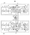
図1は、本発明による鉄道車両用電力変換器の制御装置の一実施形態を示す。
図1において、第1の駆動システム1000は次のように構成する。
エンジン1及びエンジン1に軸によって直結された発電機2は3相(U,V,W)の交流電力を発生し、コンバータ装置3はこの交流電力を直流電力に変換して出力する。即ち、エンジン1、発電機2及びコンバータ装置3により直流電源装置101を構成する。
インバータ装置4は、コンバータ装置3から出力される直流電力、或いは電力蓄電装置である二次電池装置6より出力される直流電力をスイッチ11を介して入力し、可変電圧、可変周波数の3相交流電力に変換し、誘導電動機5に供給する。即ち、インバータ装置4、誘導電動機5は、直流電源装置101及び二次電池装置6よりなる電力供給源102の負荷103として構成する。
二次電池装置6は、コンバータ装置3の出力に並列に接続され、後述のように車両の起動時やインバータ装置4が使用する電力に比べ、直流電源装置101の出力が不足する時等に電力を補給する。また、逆にインバータ装置4が使用する電力に比べ、直流電源装置101の出力が過剰な時、或いはブレーキ時におけるインバータ装置6の回生電力等を充電蓄積する。
平滑コンデンサ7は、インバータ装置4の入力に並列に接続され、インバータ入力電圧の変動を抑制する。
【0008】
一方、制御部10は、電流検出器9aで検出したコンバータ出力電流Isと電圧検出器8aで検出した電源電圧Vd1、差電圧検出部12から出力される差電圧ΔVd1及び発電機回転周波数Frgによりコンバータ制御演算を実行し、コンバータ装置3に対してコンバータPWM制御信号Sgcを出力すると共に、スイッチ11の開閉信号Slbを出力する。
また、制御部10は、電流検出器9b,9c,9dで検出した電動機電流Iu,Iv,Iwと電圧検出器8bで検出した直流電圧Ecf及び電動機回転周波数Frmによりインバータ制御演算を実行し、インバータ装置4に対してインバータPWM制御信号Sgiを出力する。
更に、制御部10は、二次電池装置6から出力される二次電池電流Ib、二次電池電圧Vb及び二次電池温度Tbにより二次電池の稼動状態を監視し、コンバータの出力を制御することによって二次電池の充放電量の制御を行う。
【0009】
第2の駆動システム2000は、第1の駆動システム1000と同様に構成された駆動システムである。そして、これらの駆動システム1000及び2000は並列に運転する為、負荷であるインバータ装置4とインバータ装置4’の直流入力端を接続する。
差電圧検出部12は、第1,第2の駆動システム1000及び2000から出力される電源電圧Vd1,Vd2を入力として両駆動システム間の電圧差を求め、差電圧ΔVd1,ΔVd2を各制御部10,10’に出力する。
【0010】
次に、本実施形態の動作について説明する。
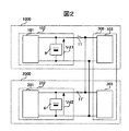
図2は、図1を簡略化したブロック図である。今、電力供給源102が開放されている状態とする。一方、負荷103,203は負荷群300として存在しており、電力供給源202より給電されているとする。電力供給源102の出力を出力電圧Vd1、電力供給源202の出力を出力電圧Vd2とし、その差を差電圧ΔV(ΔVd1又はΔVd2)とする。
スイッチ11を投入し、電力供給源102を接続すると、差電圧ΔVによる電流が電力供給源102,202の間に相互の電圧差をうめるように流れる。
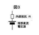
ここで、図3に、二次電池の概略の等価回路を示す。近似的には二次電池は理想的な直流電圧源に内部抵抗Rを持つ直流源である。従って、上記のように電力供給源102を接続しようとするとき、電池6に入出力する電流は、最悪負荷群300及電力供給源102の合成インピーダンスが0Ωとしても、電池6の内部抵抗Rで制限される。即ち、図4に示すように、内部抵抗R及び差電圧ΔVで定まる電流ΔV/Rに制限される。従って、ΔVを電池に許される最大電流Imaxと内部抵抗Rの積以下に制御した状態で接続すれば、Imax以上の電流は流れない。
【0011】
そこで、図1において、出力電圧Vd1≦出力電圧Vd2とするとき、差電圧検出部12によって検出した差電圧ΔVd1を制御部10に入力する。制御部10では、コンバータ装置3を制御し、差電圧ΔVd1が二次電池6に許される最大電流Imaxと内部抵抗Rの積以下になるように二次電池6を充電する。
この充電によって出力電圧Vd1と出力電圧Vd2の差電圧ΔVd1が二次電池6の内部抵抗Rと入出力許容電流値Imaxの積によって設定する値以下になったとき、電力供給源102を電力供給源202に接続すれば、差電圧ΔVd1による大電流が流れることなく、機器破損等の事故を未然に防ぐことができる。
また、出力電圧Vd1≧出力電圧Vd2のときも同様である。すなわち、差電圧検出部12によって検出した差電圧ΔVd2を制御部10’に入力する。制御部10’では、コンバータ装置3’を制御し、差電圧ΔVd2が二次電池6’に許される最大電流Imaxと内部抵抗Rの積以下になるように二次電池6’を充電する。
この充電によって出力電圧Vd1と出力電圧Vd2の差電圧ΔVd2が二次電池6’の内部抵抗Rと入出力許容電流値Imaxの積によって設定する値以下になったとき、電力供給源102を電力供給源202に接続すれば、差電圧ΔVd2による大電流が流れることなく、機器破損等の事故を未然に防ぐことができる。
以上のように、本実施形態によれば、開放された電力供給源を負荷に接続するとき、差電圧ΔV(ΔVd1又はΔVd2)を監視し、制御することにより、第1の駆動システム1000と第2の駆動システム2000を安全に接続することが可能である。
【0012】
【発明の効果】
以上説明したように、本発明によれば、開放されている電力供給源側と、接続先である負荷側の直流電圧を監視すると共に、その電圧差が所定の値以下であることを検出し、両電力供給源を接続するので、電力供給源間に大電流が流れることなく、機器破損等の事故を未然に防ぐことができ、複数の電源系を安全に接続することができる。
【図面の簡単な説明】
【図1】本発明による鉄道車両用電力変換器の制御装置の一実施形態
【図2】図1に示す実施形態の簡略ブロック図
【図3】二次電池の概略等価回路を示す図
【図4】本発明の許容差電圧を説明する図
【符号の説明】
1,1’…エンジン、2,2’…発電機、3,3’…コンバータ装置、4,4’…インバータ装置、5,5’…誘導電動機、6,6’…バッテリ(二次電池)装置、7,7’…平滑コンデンサ、8a,8b,8a’,8b’…電圧検出器、9a,9b,9c,9d,9a’,9b’,9c’,9d’…電流検出器、10,10’…制御部、11,11’…スイッチ、12…差電圧検出部、101,201…直流電源装置、102,202…電力供給源、103,203…負荷、1000…第1の駆動システム、2000…第2の駆動システム[0001]
TECHNICAL FIELD OF THE INVENTION
The present invention relates to a control device for a railway vehicle power converter having a plurality of power supply sources including a power supply device for generating DC power and a power storage device for supplying DC power.
[0002]
[Prior art]
Diesel engine-type railway vehicles (hereinafter referred to as railcars) are referred to as electric railway vehicles (hereinafter referred to as electric vehicles) in order to deal with environmental problems such as noise and exhaust and to improve system maintainability. Hybridization for common use of components is being considered.
In this system, a generator is driven by an engine to generate AC power, which is temporarily converted to DC power by a converter device. This DC power is further converted into AC power of a variable voltage and a variable rotation frequency by an inverter device to drive the induction motor.
In addition, the converter DC output unit has a power storage device that can supply and store power such as a secondary battery in parallel. The engine and generator can be powered by the storage of regenerative energy during braking and power supply from the power storage device. The power generation efficiency of the power generation portion composed of the converter is not restricted by the generation of the power amount required for the operation of the vehicle, but the operation can be performed with a high degree of freedom to improve the power generation efficiency.
As such a system, a system for a hybrid electric vehicle has been reported (for example, Patent Document 1).
[0003]
[Patent Document 1]
JP-A-10-191503
[Problems to be solved by the invention]
In the above known system, the power supply side is one system, and connection of a plurality of sets of power supply side devices is not considered.
However, a railway vehicle requires about 10 times as much electric power as an electric vehicle, and if a failure occurs on the power supply side, it becomes impossible to run. It is also conceivable that there is a desire to make the power supply side a dual system.
Further, in a railway vehicle, it is a common practice to connect the vehicles and use the composition by a plurality of vehicles. Therefore, it is sufficiently possible that the electric system has a plurality of power supply systems. However, if the power supply is composed of multiple systems, some of the systems will need to be opened or connected to the system again from the open state. It can be assumed from the aspect of usage such as.
At this time, particularly when the open power supply system is connected to the system again from the open state, the power supply system that has been individually managed up to that time is connected. In this system, a battery or the like, which is a large energy source, is built-in.When the power supply system is connected, depending on the state of the power supply, for example, when the charging states of the secondary batteries are greatly different from each other, a large current flows, There is a problem that it may be damaged.
A method of inserting a resistor for a short time when the power supply system is connected to prevent a large current from flowing is also conceivable. However, this method requires at least an energy enough to drive a motor for driving a railway vehicle for several seconds to several tens of seconds. Is consumed, and not only is a considerable amount of equipment required, but it is not preferable from the viewpoint of handling and energy saving.
[0005]
An object of the present invention is to connect a plurality of power supply systems safely and without damage to equipment in a hybrid type railway vehicle including a plurality of power supply systems.
[0006]
[Means for Solving the Problems]
In order to solve the above problem, a power supply device that generates DC power and a plurality of power supply sources including a power storage device that supplies and stores DC power are provided. A system in which a plurality of sets of power supply sources are interconnected between an inverter device and a switch by being connected to an inverter device which is individually supplied with power via a switch capable of opening and closing, and wherein a plurality of sets of power supply sources are provided. Are electrically opened by a switch, and when the open power supply is connected to the power supply of the connection partner, the DC output voltage of the open power supply and the connection partner Monitoring the DC output voltage of the power supply of the power supply source, and when the voltage difference between the two DC output voltages is not less than the predetermined difference voltage, the power storage device of the open power supply source or the power supply source of the connection partner side Charge the , Connect the power supply in an open state.
[0007]
BEST MODE FOR CARRYING OUT THE INVENTION
Hereinafter, embodiments of the present invention will be described with reference to the drawings.
FIG. 1 shows an embodiment of a control device for a power converter for a railway vehicle according to the present invention.
In FIG. 1, the
The
The inverter device 4 inputs the DC power output from the converter device 3 or the DC power output from the secondary battery device 6 which is a power storage device via the
The secondary battery device 6 is connected in parallel to the output of the converter device 3, and when the output of the DC
The
[0008]
On the other hand, the
Further, the
Further, the
[0009]
The
The difference
[0010]
Next, the operation of the present embodiment will be described.
FIG. 2 is a simplified block diagram of FIG. Now, assume that the
When the
Here, FIG. 3 shows a schematic equivalent circuit of the secondary battery. Approximately, a secondary battery is a DC source having an internal resistance R in addition to an ideal DC voltage source. Therefore, when the
[0011]
Therefore, in FIG. 1, when the output voltage Vd1 ≦ the output voltage Vd2, the difference voltage ΔVd1 detected by the difference
When the voltage difference ΔVd1 between the output voltage Vd1 and the output voltage Vd2 falls below the value set by the product of the internal resistance R of the secondary battery 6 and the input / output allowable current value Imax, the
The same applies when output voltage Vd1 ≧ output voltage Vd2. That is, the difference voltage ΔVd2 detected by the
When the difference voltage ΔVd2 between the output voltage Vd1 and the output voltage Vd2 becomes equal to or less than the value set by the product of the internal resistance R of the secondary battery 6 ′ and the input / output allowable current value Imax, the
As described above, according to the present embodiment, when the open power supply is connected to the load, the
[0012]
【The invention's effect】
As described above, according to the present invention, the DC voltage on the open power supply source side and the DC voltage on the load side that is the connection destination are monitored, and it is detected that the voltage difference is equal to or less than a predetermined value. Since both power supply sources are connected, a large current does not flow between the power supply sources, accidents such as equipment breakage can be prevented beforehand, and a plurality of power supply systems can be safely connected.
[Brief description of the drawings]
FIG. 1 is an embodiment of a control device of a power converter for a railway vehicle according to the present invention; FIG. 2 is a simplified block diagram of the embodiment shown in FIG. 1; FIG. 3 is a diagram showing a schematic equivalent circuit of a secondary battery; 4 is a diagram for explaining a tolerance voltage according to the present invention.
1, 1 '... engine, 2, 2' ... generator, 3, 3 '... converter device, 4, 4' ... inverter device, 5, 5 '... induction motor, 6, 6' ... battery (secondary battery) Device, 7, 7 '... smoothing capacitor, 8a, 8b, 8a', 8b '... voltage detector, 9a, 9b, 9c, 9d, 9a', 9b ', 9c', 9d '... current detector, 10, 10 ': control unit, 11, 11': switch, 12: difference voltage detection unit, 101, 201: DC power supply, 102, 202: power supply source, 103, 203: load, 1000: first drive system, 2000: Second drive system
Claims (5)
Priority Applications (1)
| Application Number | Priority Date | Filing Date | Title |
|---|---|---|---|
| JP2003125151A JP4166618B2 (en) | 2003-04-30 | 2003-04-30 | Induction motor drive system for railway vehicles |
Applications Claiming Priority (1)
| Application Number | Priority Date | Filing Date | Title |
|---|---|---|---|
| JP2003125151A JP4166618B2 (en) | 2003-04-30 | 2003-04-30 | Induction motor drive system for railway vehicles |
Publications (2)
| Publication Number | Publication Date |
|---|---|
| JP2004336833A true JP2004336833A (en) | 2004-11-25 |
| JP4166618B2 JP4166618B2 (en) | 2008-10-15 |
Family
ID=33502502
Family Applications (1)
| Application Number | Title | Priority Date | Filing Date |
|---|---|---|---|
| JP2003125151A Expired - Fee Related JP4166618B2 (en) | 2003-04-30 | 2003-04-30 | Induction motor drive system for railway vehicles |
Country Status (1)
| Country | Link |
|---|---|
| JP (1) | JP4166618B2 (en) |
Cited By (7)
| Publication number | Priority date | Publication date | Assignee | Title |
|---|---|---|---|---|
| JP2007195334A (en) * | 2006-01-19 | 2007-08-02 | Hitachi Ltd | Railcar drive device |
| GB2434928A (en) * | 2006-02-02 | 2007-08-08 | Milwaukee Electric Tool Corp | Generator system with DC storage |
| CN103171566A (en) * | 2011-12-20 | 2013-06-26 | 株式会社东芝 | Hybrid electric locomotive |
| KR101305003B1 (en) * | 2012-04-05 | 2013-09-05 | 삼성중공업 주식회사 | Power distribution system, propulsion system, and dynamic positioning system including the same |
| WO2015001605A1 (en) * | 2013-07-01 | 2015-01-08 | 三菱電機株式会社 | Hybrid drive system |
| WO2015001621A1 (en) * | 2013-07-02 | 2015-01-08 | 三菱電機株式会社 | Hybrid drive system |
| CN107791851A (en) * | 2016-09-06 | 2018-03-13 | 福特全球技术公司 | Non-firm power supply for main capacitor electric discharge |
-
2003
- 2003-04-30 JP JP2003125151A patent/JP4166618B2/en not_active Expired - Fee Related
Cited By (19)
| Publication number | Priority date | Publication date | Assignee | Title |
|---|---|---|---|---|
| JP2007195334A (en) * | 2006-01-19 | 2007-08-02 | Hitachi Ltd | Railcar drive device |
| GB2434928A (en) * | 2006-02-02 | 2007-08-08 | Milwaukee Electric Tool Corp | Generator system with DC storage |
| GB2434928B (en) * | 2006-02-02 | 2010-04-28 | Milwaukee Electric Tool Corp | Generator systems and methods |
| US7781902B2 (en) | 2006-02-02 | 2010-08-24 | Milwaukee Electric Tool Corporation | Generator systems and methods |
| US9186997B2 (en) | 2011-12-20 | 2015-11-17 | Kabushiki Kaisha Toshiba | Hybrid electric locomotive |
| CN103171566A (en) * | 2011-12-20 | 2013-06-26 | 株式会社东芝 | Hybrid electric locomotive |
| JP2013129226A (en) * | 2011-12-20 | 2013-07-04 | Toshiba Corp | Hybrid electric locomotive |
| CN103171566B (en) * | 2011-12-20 | 2016-04-27 | 株式会社东芝 | Hybrid battery locomotive |
| KR101305003B1 (en) * | 2012-04-05 | 2013-09-05 | 삼성중공업 주식회사 | Power distribution system, propulsion system, and dynamic positioning system including the same |
| US9493077B2 (en) | 2013-07-01 | 2016-11-15 | Mitsubishi Electric Corporation | Hybrid drive system |
| WO2015001605A1 (en) * | 2013-07-01 | 2015-01-08 | 三菱電機株式会社 | Hybrid drive system |
| JP6072912B2 (en) * | 2013-07-01 | 2017-02-01 | 三菱電機株式会社 | Hybrid drive system |
| JPWO2015001605A1 (en) * | 2013-07-01 | 2017-02-23 | 三菱電機株式会社 | Hybrid drive system |
| WO2015001621A1 (en) * | 2013-07-02 | 2015-01-08 | 三菱電機株式会社 | Hybrid drive system |
| JP5944050B2 (en) * | 2013-07-02 | 2016-07-05 | 三菱電機株式会社 | Hybrid drive system |
| US10065511B2 (en) | 2013-07-02 | 2018-09-04 | Mitsubishi Electric Corporation | Hybrid drive system |
| EP3000646B1 (en) | 2013-07-02 | 2020-05-13 | Mitsubishi Electric Corporation | Hybrid drive system |
| CN107791851A (en) * | 2016-09-06 | 2018-03-13 | 福特全球技术公司 | Non-firm power supply for main capacitor electric discharge |
| CN107791851B (en) * | 2016-09-06 | 2022-10-11 | 福特全球技术公司 | Backup power supply for discharging a main capacitor |
Also Published As
| Publication number | Publication date |
|---|---|
| JP4166618B2 (en) | 2008-10-15 |
Similar Documents
| Publication | Publication Date | Title |
|---|---|---|
| US7269535B2 (en) | Fault diagnosing apparatus for vehicle and fault diagnosing method for vehicle | |
| US8659182B2 (en) | Power supply system and electric powered vehicle including power supply system, and method for controlling power supply system | |
| CA2289332C (en) | Method and apparatus for a hybrid battery configuration for use in an electric or hybrid electric motive power system | |
| JP5014518B2 (en) | Electric vehicle propulsion control device and railway vehicle system | |
| JP5844787B2 (en) | Auxiliary drive device and manufacturing method thereof | |
| RU2413352C1 (en) | Device of power supply for transport vehicle | |
| CN101842957B (en) | Power supply device | |
| US20130127247A1 (en) | Battery management apparatus for an electric vehicle, and method for managing same | |
| CN108292848A (en) | Automobile double voltage battery charging system | |
| JP2006219128A (en) | Secondary battery device for hybrid rolling stock | |
| US20080303349A1 (en) | Two-source inverter | |
| JP2004056934A (en) | Auxiliary power unit | |
| JP2004072892A (en) | Apparatus and method for driving electrical load and computer-readable recording medium with program recorded thereon for causing computer to drive electrical load | |
| JP5514459B2 (en) | Charging system | |
| US11794597B2 (en) | On-board vehicle electrical system having an accumulator, an alternating voltage connection and a direct voltage connection | |
| JP4166618B2 (en) | Induction motor drive system for railway vehicles | |
| US7843713B2 (en) | Method of driving DC/DC converter, and DC/DC converter | |
| JP6818835B1 (en) | Power controller | |
| JP3972322B2 (en) | Electric vehicle control device | |
| JP7096203B2 (en) | Power system | |
| WO2014041695A1 (en) | Propulsion control device for hybrid vehicle | |
| JP6896171B2 (en) | Drive control device and drive device for railway vehicles | |
| JP5385728B2 (en) | Control method and control apparatus | |
| WO2020075504A1 (en) | Railroad vehicle drive system and method for charging electrical storage device in railroad vehicle | |
| US10160336B2 (en) | Multiphase converter auxiliary power reduction |
Legal Events
| Date | Code | Title | Description |
|---|---|---|---|
| A621 | Written request for application examination |
Free format text: JAPANESE INTERMEDIATE CODE: A621 Effective date: 20050809 |
|
| A977 | Report on retrieval |
Free format text: JAPANESE INTERMEDIATE CODE: A971007 Effective date: 20080411 |
|
| RD02 | Notification of acceptance of power of attorney |
Free format text: JAPANESE INTERMEDIATE CODE: A7422 Effective date: 20080411 |
|
| A131 | Notification of reasons for refusal |
Free format text: JAPANESE INTERMEDIATE CODE: A131 Effective date: 20080513 |
|
| A521 | Request for written amendment filed |
Free format text: JAPANESE INTERMEDIATE CODE: A523 Effective date: 20080701 |
|
| TRDD | Decision of grant or rejection written | ||
| A01 | Written decision to grant a patent or to grant a registration (utility model) |
Free format text: JAPANESE INTERMEDIATE CODE: A01 Effective date: 20080729 |
|
| A01 | Written decision to grant a patent or to grant a registration (utility model) |
Free format text: JAPANESE INTERMEDIATE CODE: A01 |
|
| A61 | First payment of annual fees (during grant procedure) |
Free format text: JAPANESE INTERMEDIATE CODE: A61 Effective date: 20080730 |
|
| R150 | Certificate of patent or registration of utility model |
Free format text: JAPANESE INTERMEDIATE CODE: R150 |
|
| FPAY | Renewal fee payment (event date is renewal date of database) |
Free format text: PAYMENT UNTIL: 20110808 Year of fee payment: 3 |
|
| FPAY | Renewal fee payment (event date is renewal date of database) |
Free format text: PAYMENT UNTIL: 20120808 Year of fee payment: 4 |
|
| FPAY | Renewal fee payment (event date is renewal date of database) |
Free format text: PAYMENT UNTIL: 20120808 Year of fee payment: 4 |
|
| FPAY | Renewal fee payment (event date is renewal date of database) |
Free format text: PAYMENT UNTIL: 20130808 Year of fee payment: 5 |
|
| LAPS | Cancellation because of no payment of annual fees |