JP2004332673A - Intake noise reduction device for vehicular internal combustion engine - Google Patents
Intake noise reduction device for vehicular internal combustion engine Download PDFInfo
- Publication number
- JP2004332673A JP2004332673A JP2003132524A JP2003132524A JP2004332673A JP 2004332673 A JP2004332673 A JP 2004332673A JP 2003132524 A JP2003132524 A JP 2003132524A JP 2003132524 A JP2003132524 A JP 2003132524A JP 2004332673 A JP2004332673 A JP 2004332673A
- Authority
- JP
- Japan
- Prior art keywords
- intake
- noise reduction
- intake duct
- main body
- intake noise
- Prior art date
- Legal status (The legal status is an assumption and is not a legal conclusion. Google has not performed a legal analysis and makes no representation as to the accuracy of the status listed.)
- Abandoned
Links
Images


Abstract
Description
【0001】
【発明の属する技術分野】
本発明は、車両用内燃機関の吸気音低減装置に関する。
【0002】
【従来の技術】
従来、車両用内燃機関においては、吸気弁の開閉に伴い発生する圧力波が、吸気管、エアクリーナーを介して吸気系の最上流端となるエアクリーナに空気を導入する空気ダクトの空気取入れ口まで伝播すること等によって、乗員にとって不快な吸気音が発生するという問題がある。
【0003】
そこで、下記特許文献1には、吸気ダクトの外周に複数の小孔を開口するとともに、その小孔を吸音材で覆うことによって吸気音を低減することが開示されている。
【0004】
【特許文献1】
特開2000−282985号公報
【発明が解決しようとする課題】
【0005】
しかしながら、上述の特許文献1によれば、吸気ダクトの外周に開口部が開口されているため、吸気ダクト内の密閉度が低下して、吸気ロスが生じ、エンジントルクが低下するおそれがある。
【0006】
本発明は、以上のような課題に勘案してなされたもので、その目的は、エンジントルクの低下を抑制しつつ吸気音を低減することが可能な車両用内燃機関の吸気音低減装置を提供することにある。
【0007】
【課題を解決するための手段】
前記目的を達成するため、本発明にあってはその解決手法として次のようにしてある。すなわち、本発明の第1の構成において、エアクリーナに空気を供給する吸気ダクトを備えた車両用内燃機関の吸気音低減装置において、上記吸気ダクトには、略円筒状に形成された本体部と、該本体部外周に形成された開口部と、該開口部に対向して設けられた吸音材とから構成される吸気音低減部材が挿入されるよう構成してある。
本発明の第1の構成によれば、吸気ダクトとは別部材として構成された吸気音低減部材に開口部が形成されるため、吸気ダクト本体に開口部を形成する場合に対して吸気ダクトの密閉度が向上し、エンジントルクの低下を抑制しつつ吸気音を低減することができる。
【0008】
本発明の第2の構成において、上記本体部には、上記吸気ダクトの空気取入れ口側に拡径されたファンネル状の吸入部が形成されるとともに、上記開口部は、上記本体部から吸入部に亘って形成されるよう構成してある。
ここで、吸気音低減効果を高めるためには、吸気ダクトの先端となる空気取入れ口に、開口部を形成するとともに吸気音材を設けることが望ましいものである。これは、吸気ダクトの先端となる空気取入れ口が、吸気音全周波数の圧力波の節となる位置であり、全周波数の消音を図ることが可能となるためである。
しかしながら、単に、開口部を吸気ダクトの空気取入れ口付近に形成すると、空気取入れ口付近における吸気ダクトの肉圧が薄くなり、吸気ダクトの剛性が低下するおそれがある。
本発明の第2の構成によれば、吸気ダクトとは別部材として構成された吸気音低減部材に開口部が形成されるため、吸気ダクト自体の剛性を確保しつつ、全周波数の消音を図ることができる。
また、吸気音低減部材の本体部の空気取入れ口側には、拡径されたファンネル状の吸入部が形成されているため、圧力波の節となる位置が吸気ダクト空気取入れ口よりもエアクリーナ側にずれ、開口部の形成位置を吸気ダクト空気取入れ口よりもエアクリーナ側にずらして形成することができる。
従って、吸気音低減部材に形成される開口部の開口位置を先端側よりもエアクリーナ側にずらして形成することができるため、空気取入れ口付近の肉厚を確保でき、吸気音低減部材の剛性も確保しつつ、全周波数の消音を図ることができる。
【0009】
【発明の効果】
本発明によれば、エンジントルクの低下を抑制しつつ、吸気音を低減することができる。
【0010】
【発明の実施の形態】
以下、本発明の実施の形態を図面に基づいて説明する。
図1はエンジンのサージタンクよりも上流側の吸気系を示した全体図、図2は吸気ダクトの側面図、図3は吸気音低減部材の側面図である。
尚、本実施形態では、4気筒直列型ガソリンエンジンに適用した例を示す。
【0011】
図1において、1はその下流端がサージタンク(不図示)に接続される吸気管、2はエアクリーナ、3は樹脂製の吸気ダクト、4、5は、それぞれ異なる周波数の吸気音を消音するためのレゾネータ、6は吸気ダクト3に挿入される吸気音低減部材である。
【0012】
吸気ダクト3には、図2に示すように、その一端側に、エアクリーナ2に接続されるエアクリーナ接続部3aが形成されるとともに、他端側に、空気を取り入れるための空気取入れ口3bが形成されている。
【0013】
また、吸気ダクト3の空気取入れ口3a側に形成された直線部3cには、後述する吸気音低減部材6が挿入されるよう構成されている。
吸気音低減部材6は、その一端が吸気ダクト3の絞り部3dに当接され、他端が空気取入れ口3bの内周に当接されるよう、挿入されている。
この時、直線部3cにおける吸気ダクト3の内径d1は、直線部3c以外における吸気ダクト3の内径d2よりも大きく形成される一方、吸気音低減部材6の内径d3は、直線部3c以外の内径d2と同径に形成されており、吸気ダクト3内に吸気音低減部材6が挿入された場合であっても、吸気ダクト3のエアクリーナ接続部3aから空気取入れ口3bに亘ってその内径を同径に維持されることになる。
【0014】
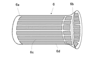
また、吸気音低減部材6は、図3に示すように、円筒状に形成された樹脂製の本体部6aと、その本体部6aが吸気ダクト3内に挿入された時、吸気ダクト3の空気取入れ口3b側に位置する側に本体部6aよりも徐々に拡径されたファンネル状の吸入部6bと、本体部6aの外周全周及び吸入部6bの外周全周に亘ってそれぞれその長手方向に延びる略長方形状に形成された複数の開口部6cと、その開口部6cを本体部6a、吸入部6bの内周側から覆う不織布等の多孔質繊維材料等から成る吸音材6dとから構成されている。
【0015】
以上のように、本実施の形態によれば、吸気ダクト3とは別部材として構成された吸気音低減部材6に開口部6cが形成されるため、吸気ダクト3本体に開口部6cを形成する場合に対して吸気ダクト3の密閉度が向上し、エンジントルクの低下を抑制しつつ吸気音を低減することができる。
また、吸気ダクト3とは別部材として構成された吸気音低減部材6の本体部6aと、吸入部6bとに亘って開口部6cが形成されるため、吸気ダクト3及び吸気音低減部材6の剛性を確保しつつ、全周波数の消音を図ることができる。
また、吸気音低減部材6の本体部6aの空気取入れ口側には、拡径されたファンネル状の吸入部6bが形成されているため、圧力波の節となる位置が吸気ダクト3の空気取入れ口3bよりもエアクリーナ2側にずれ、開口部6cの形成位置を吸気ダクト3の空気取入れ口3bよりもエアクリーナ2側にずらして形成することができる。
従って、吸気音低減部材6に形成される開口部6cの開口位置を先端側よりもエアクリーナ2側にずらして形成することができるため、吸気音低減部材6の剛性も確保しつつ、全周波数の消音を図ることができる。
また、直線部3cにおける吸気ダクト3の内径d1は、直線部3c以外における吸気ダクト3の内径d2よりも大きく形成される一方、吸気音低減部材6の内径d3は、直線部3c以外の内径d2と同径に形成されており、吸気ダクト3内に吸気音低減部材6が挿入された場合であっても、吸気ダクト3のエアクリーナ接続部3aから空気取入れ口3bに亘ってその内径を同径に維持されることになる。
従って、吸気音低減部材6を吸気ダクト3内に挿入するに当たり、吸気抵抗を軽減でき、エンジントルクの低下を抑制することができる。
【0016】
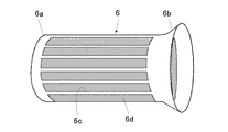
尚、本実施形態によれば、開口部6cを本体部6aと、吸入部6bとに亘って形成する例を示したが、図4に示すように、開口部6cを本体部6aのみに形成するようにしてもよい。
【0017】
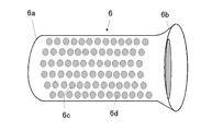
また、本実施形態によれば、開口部6cの形状を略長方形状とする例を示したが、図5に示すように、円形状に形成するようにしてもよい。
【0018】
また、本実施形態では、4気筒直列型エンジンに適用する例を示したが、気筒数が4気筒以外のガソリンエンジンや、ディーゼルエンジンに適用することも可能である。
【図面の簡単な説明】
【図1】本発明の実施形態に係るエンジンのサージタンクよりも上流側の吸気系を示した全体図。
【図2】本発明の実施形態に係る吸気ダクトの側面図。
【図3】本発明の実施形態に係る吸気音低減部材の側面図。
【図4】本発明の他の実施形態に係る吸気音低減部材の側面図。
【図5】本発明の他の実施形態に係る吸気音低減部材の側面図。
【符号の説明】
1:吸気管
2:エアクリーナ
3:吸気ダクト
3a:エアクリーナ接続部
3b:空気取入れ口
6:吸気音低減部材
6a:本体部
6b:吸入部
6c:開口部
6d:吸音材[0001]
TECHNICAL FIELD OF THE INVENTION
The present invention relates to an intake noise reduction device for a vehicle internal combustion engine.
[0002]
[Prior art]
Conventionally, in a vehicle internal combustion engine, a pressure wave generated due to opening and closing of an intake valve is transmitted through an intake pipe and an air cleaner to an air intake of an air duct which introduces air to an air cleaner at the most upstream end of an intake system. There is a problem that an uncomfortable intake sound is generated for the occupant due to the propagation or the like.
[0003]
Therefore, Patent Document 1 below discloses that a plurality of small holes are opened on the outer periphery of an intake duct, and the small holes are covered with a sound absorbing material to reduce intake noise.
[0004]
[Patent Document 1]
Japanese Patent Application Laid-Open No. 2000-282895 [Problems to be Solved by the Invention]
[0005]
However, according to Patent Literature 1 described above, since the opening is formed on the outer periphery of the intake duct, the degree of sealing in the intake duct is reduced, and intake loss may occur, and engine torque may be reduced.
[0006]
SUMMARY OF THE INVENTION The present invention has been made in view of the above problems, and has as its object to provide an intake noise reduction device for a vehicle internal combustion engine capable of reducing intake noise while suppressing a decrease in engine torque. Is to do.
[0007]
[Means for Solving the Problems]
In order to achieve the above object, the present invention provides the following as a solution. That is, in the first configuration of the present invention, in the intake noise reduction device for a vehicle internal combustion engine including an intake duct that supplies air to an air cleaner, the intake duct includes a main body formed in a substantially cylindrical shape, An intake noise reduction member including an opening formed on the outer periphery of the main body and a sound absorbing material provided to face the opening is inserted.
According to the first configuration of the present invention, since the opening is formed in the intake noise reduction member that is configured as a member separate from the intake duct, the intake duct is not provided with respect to the case where the opening is formed in the intake duct body. The degree of sealing is improved, and intake noise can be reduced while suppressing a decrease in engine torque.
[0008]
In the second configuration of the present invention, a funnel-shaped suction portion whose diameter is increased toward the air intake side of the intake duct is formed in the main body portion, and the opening is formed from the main body portion to the suction portion. It is constituted so that it may be formed over.
Here, in order to enhance the intake noise reduction effect, it is desirable to form an opening and provide an intake sound material in the air intake opening at the tip of the intake duct. This is because the air intake, which is the tip of the intake duct, is a position that serves as a node for pressure waves of all frequencies of the intake sound, so that all frequencies can be silenced.
However, if the opening is simply formed in the vicinity of the air intake of the intake duct, the wall pressure of the intake duct near the air intake becomes thin, and the rigidity of the intake duct may be reduced.
According to the second configuration of the present invention, since the opening is formed in the intake noise reducing member formed as a member separate from the intake duct, noise reduction of all frequencies is achieved while securing the rigidity of the intake duct itself. be able to.
In addition, since a funnel-shaped suction portion having an enlarged diameter is formed on the air intake side of the main body of the intake noise reducing member, the position of the node of the pressure wave is closer to the air cleaner than the intake duct air intake. In this case, the position of the opening can be shifted to the air cleaner side from the intake duct air intake port.
Therefore, since the opening position of the opening formed in the intake noise reduction member can be shifted toward the air cleaner side from the front end side, the thickness near the air intake can be secured, and the rigidity of the intake noise reduction member can be improved. It is possible to silence all the frequencies while securing.
[0009]
【The invention's effect】
According to the present invention, intake noise can be reduced while suppressing a decrease in engine torque.
[0010]
BEST MODE FOR CARRYING OUT THE INVENTION
Hereinafter, embodiments of the present invention will be described with reference to the drawings.
1 is an overall view showing an intake system upstream of a surge tank of an engine, FIG. 2 is a side view of an intake duct, and FIG. 3 is a side view of an intake noise reducing member.
In this embodiment, an example in which the present invention is applied to a 4-cylinder in-line gasoline engine will be described.
[0011]
In FIG. 1, reference numeral 1 denotes an intake pipe whose downstream end is connected to a surge tank (not shown), 2 denotes an air cleaner, 3 denotes a resin intake duct, and 4 and 5 deactivate intake sounds of different frequencies. Is an intake noise reduction member inserted into the
[0012]
As shown in FIG. 2, the
[0013]
In addition, an intake
The intake
At this time, the inner diameter d1 of the
[0014]
As shown in FIG. 3, the intake
[0015]
As described above, according to the present embodiment, since opening 6c is formed in intake
Further, since the opening 6c is formed over the
Further, since a funnel-
Therefore, the opening position of the
The inner diameter d1 of the
Accordingly, when the intake
[0016]
According to the present embodiment, an example in which the
[0017]
Further, according to the present embodiment, the example in which the shape of the opening 6c is substantially rectangular is shown, but the
[0018]
Further, in the present embodiment, an example in which the invention is applied to a four-cylinder in-line type engine has been described. However, the invention may be applied to a gasoline engine having a number of cylinders other than four or a diesel engine.
[Brief description of the drawings]
FIG. 1 is an overall view showing an intake system upstream of a surge tank of an engine according to an embodiment of the present invention.
FIG. 2 is a side view of the intake duct according to the embodiment of the present invention.
FIG. 3 is a side view of the intake noise reducing member according to the embodiment of the present invention.
FIG. 4 is a side view of an intake noise reducing member according to another embodiment of the present invention.
FIG. 5 is a side view of an intake noise reducing member according to another embodiment of the present invention.
[Explanation of symbols]
1: intake pipe 2: air cleaner 3:
Claims (2)
上記吸気ダクトには、略円筒状に形成された本体部と、該本体部外周に形成された開口部と、該開口部に対向して設けられた吸音材とから構成される吸気音低減部材が挿入されていることを特徴とする車両用内燃機関の吸気音低減装置。In an intake noise reduction device for a vehicle internal combustion engine having an intake duct for supplying air to an air cleaner,
The intake duct has an intake sound reducing member including a substantially cylindrical main body, an opening formed on the outer periphery of the main body, and a sound absorbing material provided to face the opening. An intake noise reduction device for an internal combustion engine for a vehicle, characterized in that the intake noise reduction device is inserted.
上記開口部は、上記本体部から吸入部に亘って形成されていることを特徴とする請求項1記載の車両用内燃機関の吸気音低減装置。In the main body, a funnel-shaped suction portion having an enlarged diameter on the air intake side of the intake duct is formed,
2. The intake noise reduction device for an internal combustion engine for a vehicle according to claim 1, wherein the opening is formed from the main body to a suction portion.
Priority Applications (1)
| Application Number | Priority Date | Filing Date | Title |
|---|---|---|---|
| JP2003132524A JP2004332673A (en) | 2003-05-12 | 2003-05-12 | Intake noise reduction device for vehicular internal combustion engine |
Applications Claiming Priority (1)
| Application Number | Priority Date | Filing Date | Title |
|---|---|---|---|
| JP2003132524A JP2004332673A (en) | 2003-05-12 | 2003-05-12 | Intake noise reduction device for vehicular internal combustion engine |
Publications (1)
| Publication Number | Publication Date |
|---|---|
| JP2004332673A true JP2004332673A (en) | 2004-11-25 |
Family
ID=33507343
Family Applications (1)
| Application Number | Title | Priority Date | Filing Date |
|---|---|---|---|
| JP2003132524A Abandoned JP2004332673A (en) | 2003-05-12 | 2003-05-12 | Intake noise reduction device for vehicular internal combustion engine |
Country Status (1)
| Country | Link |
|---|---|
| JP (1) | JP2004332673A (en) |
Cited By (8)
| Publication number | Priority date | Publication date | Assignee | Title |
|---|---|---|---|---|
| JP2008297936A (en) * | 2007-05-30 | 2008-12-11 | Inoac Corp | Duct for automobile |
| JP2012193692A (en) * | 2011-03-17 | 2012-10-11 | Sekiso:Kk | Intake duct |
| WO2013035614A1 (en) * | 2011-09-05 | 2013-03-14 | 株式会社Roki | Aspiration duct |
| JP2014137017A (en) * | 2013-01-17 | 2014-07-28 | Toyota Motor Corp | Intake duct |
| JP2014173521A (en) * | 2013-03-11 | 2014-09-22 | Toyota Industries Corp | Prevention structure against immersion of dust into engine at fuel injector connection part in engine head cover |
| KR101509941B1 (en) | 2013-10-21 | 2015-04-07 | 현대자동차주식회사 | Air Cleaner Resonator |
| JP2019085964A (en) * | 2017-11-09 | 2019-06-06 | トヨタ紡織株式会社 | Inlet duct for internal combustion engine |
| JP2020101146A (en) * | 2018-12-25 | 2020-07-02 | トヨタ紡織株式会社 | Air intake duct of internal combustion engine |
-
2003
- 2003-05-12 JP JP2003132524A patent/JP2004332673A/en not_active Abandoned
Cited By (10)
| Publication number | Priority date | Publication date | Assignee | Title |
|---|---|---|---|---|
| JP2008297936A (en) * | 2007-05-30 | 2008-12-11 | Inoac Corp | Duct for automobile |
| JP2012193692A (en) * | 2011-03-17 | 2012-10-11 | Sekiso:Kk | Intake duct |
| WO2013035614A1 (en) * | 2011-09-05 | 2013-03-14 | 株式会社Roki | Aspiration duct |
| JPWO2013035614A1 (en) * | 2011-09-05 | 2015-03-23 | 株式会社Roki | Air intake duct |
| JP2014137017A (en) * | 2013-01-17 | 2014-07-28 | Toyota Motor Corp | Intake duct |
| JP2014173521A (en) * | 2013-03-11 | 2014-09-22 | Toyota Industries Corp | Prevention structure against immersion of dust into engine at fuel injector connection part in engine head cover |
| KR101509941B1 (en) | 2013-10-21 | 2015-04-07 | 현대자동차주식회사 | Air Cleaner Resonator |
| JP2019085964A (en) * | 2017-11-09 | 2019-06-06 | トヨタ紡織株式会社 | Inlet duct for internal combustion engine |
| JP6992423B2 (en) | 2017-11-09 | 2022-01-13 | トヨタ紡織株式会社 | Internal combustion engine inlet duct |
| JP2020101146A (en) * | 2018-12-25 | 2020-07-02 | トヨタ紡織株式会社 | Air intake duct of internal combustion engine |
Similar Documents
| Publication | Publication Date | Title |
|---|---|---|
| EP2103801B1 (en) | Intake air sound generation device | |
| US8360199B2 (en) | Integrated mass air flow sensor and broadband silencer | |
| JP2008031918A (en) | Intake device | |
| US11255238B2 (en) | Muffler comprising a Helmholtz resonator and a vehicle comprising such a muffler | |
| JP2007321723A (en) | Intake noise amplifying device | |
| JP2004332673A (en) | Intake noise reduction device for vehicular internal combustion engine | |
| JP2003343373A (en) | Intake duct | |
| JP2008014222A (en) | Intake manifold | |
| JPS61190158A (en) | Intake system silencer for internal-combustion engine | |
| JP4573463B2 (en) | Muffler for internal combustion engine | |
| CN101294508A (en) | Silencer | |
| JP3613176B2 (en) | Intake device for internal combustion engine | |
| JP2009264244A (en) | Muffler | |
| JP3974453B2 (en) | Engine intake structure | |
| JP2009264319A (en) | Muffling device | |
| JP2004169645A (en) | Silencer for cars | |
| JP6319253B2 (en) | Intake sound amplifier for internal combustion engine | |
| JPS599046Y2 (en) | Silencer | |
| JPH04262015A (en) | Muffler device | |
| JPS63309762A (en) | Intake device for engine with supercharger | |
| JP2009144670A (en) | Silencer | |
| KR20020007327A (en) | Intake manifold for internal combustion engine | |
| JP2004293456A (en) | Muffler | |
| JP3532079B2 (en) | Internal combustion engine intake duct | |
| JP4749406B2 (en) | Resonator for internal combustion engine |
Legal Events
| Date | Code | Title | Description |
|---|---|---|---|
| A621 | Written request for application examination |
Free format text: JAPANESE INTERMEDIATE CODE: A621 Effective date: 20060123 |
|
| RD03 | Notification of appointment of power of attorney |
Effective date: 20060123 Free format text: JAPANESE INTERMEDIATE CODE: A7423 |
|
| A762 | Written abandonment of application |
Free format text: JAPANESE INTERMEDIATE CODE: A762 Effective date: 20070706 |