JP2004331307A - Delivery device for paper sheet - Google Patents
Delivery device for paper sheet Download PDFInfo
- Publication number
- JP2004331307A JP2004331307A JP2003128762A JP2003128762A JP2004331307A JP 2004331307 A JP2004331307 A JP 2004331307A JP 2003128762 A JP2003128762 A JP 2003128762A JP 2003128762 A JP2003128762 A JP 2003128762A JP 2004331307 A JP2004331307 A JP 2004331307A
- Authority
- JP
- Japan
- Prior art keywords
- paper sheet
- roller
- sheet
- paper
- friction member
- Prior art date
- Legal status (The legal status is an assumption and is not a legal conclusion. Google has not performed a legal analysis and makes no representation as to the accuracy of the status listed.)
- Granted
Links
Images


Abstract
Description
【0001】
【発明の属する技術分野】
本発明は、金融機関等において使用される現金自動取引装置や、帳票印刷装置、あるいはスキャナ等の原稿自動読取装置、印字装置などの紙葉類搬送処理装置における紙葉類の繰り出し装置に関し、特に、ステージやスタッカに積み重ねて収納されている紙葉類を、一枚ずつ分離して繰り出す紙葉類繰り出し装置に関するものである。
【0002】
【従来の技術】
金融機関の現金自動預け払い機や、帳票印刷装置、スキャナ等の原稿自動読取装置、印字装置などでは、ステージやスタッカに積み重ねてある紙葉類を1枚ずつ分離して、繰り出す必要がある。
上記紙葉類の繰り出し装置として、従来においては、例えば以下の構成のものが使用されていた。
図7は従来の紙葉類繰り出し装置の概要示す側視図、図8は図7を紙葉類の繰り出し方向(排出側)から見た正面図である。
図7において、110は矢印S方向に押圧可能なステージ130に積載された紙葉類の束で、111が一枚目の紙葉類である。120は紙葉類を繰り出し方向に前進させるためのピックローラで、これは矢印A方向に回転可能な軸122に固定されており、摩擦の小さい樹脂部123と摩擦の大きいゴム部121から成っている。尚、このピックローラ120は、図8に示すように同軸上に2個同位相で取り付けられている。
150は、複数枚の紙葉類が繰り出し方向に前進して来た時に、1枚目以外の紙葉類の前進を阻止するためのセパレータローラで、繰り出し時には停止した状態でセパレータローラが紙葉類に連れ廻りしない様にロックし、紙幣受け入れ時には繰り出しと逆方向にセパレータローラを回転駆動できる様に構成された回転軸151に支持されている。セパレータローラ150は、一般的に硬度70〜80度程度のゴム材料など、紙葉類同士の摩擦係数より若干高い値のものが使われる。
【0003】
140はセパレータローラ150と組になって紙葉類を分離搬送するためのフィードローラで、これは矢印A方向に駆動可能な回転軸143に取り付けられ、摩擦の小さい樹脂部142と、摩擦の大きいゴム部141から成っており、図8のように同軸上に同位相で複数個配置されている。
このゴム部141は樹脂部142の外周面より僅かに外径が大きく形成されている。セパレータローラ150とフィードローラ140の位置関係は、正面図である図8から見た場合、セパレータローラ150の外周面の一部は、フィードローラ140の外周面より張り出し、フィードローラとオーバーラップして配置されている。以下では、この張り出し量をオーバーラップ量と言う。
170は、セパレータローラ150を挟む形で配置されたビルスライダで、これは繰り出されて来た紙葉類の先端を前記オーバーラップ部分に導くための案内板であり、紙葉類との接触面は摩擦が小さい滑らかな状態になるよう形成されている。160は積層された紙葉類先端を揃えるための側壁である。
【0004】
次にこのような繰り出し装置の動作を説明する。図9は、ステージ130に積まれた紙葉類を繰り出している状態を示す図である。
図9において、ピックローラ120が矢印A方向に回転すると、フィードローラ140に接触している1枚目の紙葉類111が繰り出し方向に進行する。1枚目の摩擦力によって、2枚目の紙葉類も繰り出し方向に移動してゆく。 場合によっては、3枚目の紙葉類も2枚目にひきずられて繰り出し方向に移動する。同時にフィードローラ140も矢印A方向に駆動回転される。
当初はフィードローラ140の樹脂部142である外周面が一枚目の紙葉類に接触して滑っているだけであるが、フィードローラの回転が進むとゴム部141が1枚目の紙葉類に接触して、摩擦力によって1枚目を搬送してゆく。
この時、ピックローラ120は回転が進行してその樹脂部分123の外周面が一枚目の紙葉類に接触しているので、ピックローラ120による搬送力は発生していない。ピックローラ120はこの状態で停止し、以後の搬送力を発生しない。
【0005】
繰り出された1枚目の紙葉類111は、その先端がビルスライダ170に沿って進行し、フィードローラ140とセパレータローラ150のオーバーラップ間に進入する。
図10、図11は、紙葉類111がオーバラップ間に進入した状態を示しており、この状態では、図11のC部分がフィードローラ140により押しつけられ、紙葉類の先端部分はセパレータローラ150により押し上げられるので、図11に示すように、紙葉類111は波状に折り曲げられて変形する。
前述のようにセパレータローラ150は紙葉類の繰り出し方向には回転できないので、紙葉類の進行を阻止する部材として作用する。同時にオーバーラップ内に進入した3枚目の紙葉類がセパレータローラに接触すると、その摩擦力によって進行を阻止される。これは、2枚目の紙葉類と3枚目の紙葉類間の摩擦による進行力よりも、セパレータローラ150による3枚目への摩擦力の方が大きいためである。
2枚目の紙葉類は、1枚目の紙葉類から摩擦力によって進行し続けても、セパレータローラ150の接触面が円弧状なので、紙葉類の進行に伴って次第にオーバーラップ量が大きくなり、セパレータローラ150による阻止力を多く受けるようになるので、最終的には3枚目の紙葉類から受ける摩擦力とセパレータローラ150の摩擦力による阻止力によって停止する。
【0006】
1枚目の紙葉類111は、2枚目の紙葉類による摩擦力とセパレータローラ150の摩擦力による阻止力によって進行を阻止されるが、フィードローラゴム部141の摩擦力による進行力の方が大きいために、繰り出し方向に搬送されてゆく。
フィードローラ140の回転が進むと、摩擦の小さい樹脂部142外周部が紙葉類に接触するようになり、紙葉類への搬送力がなくなり、フィードローラ140はその状態で停止する。
そして図示せぬ搬送装置によって、1枚目の紙葉類のみが引き出されて搬送されてゆく。以上の動作で、積層された紙葉類から一枚目の紙葉類のみを取り出して搬送する。複数枚の紙葉類を繰り出す場合は、順次この動作を必要枚数分だけ繰り返す。
また、現金自動預け払い機における入金処理の時は、繰り出しと逆方向に紙葉類が入ってくるので、セパレータローラ150を繰り出方向と逆回転させて、セパレータローラ150を搬送ローラとして機能させる。
【0007】
また、上記紙葉類の繰り出し装置において、重送や連鎖を起こさずに紙葉類を1枚ずつ正確に送り出せるようにするため、繰り出し動作の後半において、内側のフィードローラのオーバラップ量を、外側のフィードローラのオーバラップ量よりも小さくするようにしたものが提案されている(例えば特許文献1参照)。
上記特許文献1に記載されるものは、同一の回転軸に固定された複数のフィードローラのうち、例えば内側に配置された2個のフィードローラのゴム部を外側にフィードローラのゴム部よりも短くし、繰り出し動作の後半において、内側のフィードローラのゴム部が外側のフィードローラのゴム部より早いタイミングで紙葉類から離れるように構成したものである。これにより、繰り出し動作の後半において、内側のフィードローラのオーバラップ量を、外側のフィードローラのオーバラップ量よりも小さくすることができる。このため、1枚目の紙葉類が2枚目以降の紙葉類に与える搬送力を低減させることができ、2枚目以降の紙幣の進行をセパレータにより確実に阻止することができる。
【0008】
【特許文献1】
特開2002−19985号公報
【0009】
【発明が解決しようとする課題】
海外においては、日本国内ではまず市中に出回らないような、使い古されてボロボロの、紙のコシが殆ど無くなった状態の流通券が出回っている国や地域があり、前記図7、図8に示した従来の繰り出し装置を使うと問題を生じることがある。
すなわち、この様な流通券が繰り出し機構部に進入して来ると、紙葉類先端がセパレータローラのゴム面に衝突した際、コシが無いために摩擦にまけて折れ曲がって潰れてしまい、ペーパージャムを起こしてしまうことがある。これは、セパレータローラが用紙先端の進行を妨げている状態のところに、紙葉類先端から僅かに離れた後ろ側からフィードローラで用紙を押し込むかたちで搬送力を付与しており、コシが無い紙葉類は自身の形状を保てなくなるからである。
日本国内の流通券は、コシが殆ど無くなる程使い古される前に回収・交換されるので、海外の流通券に比べるとかなり状態が良く、コシがまったく無いような流通券は殆ど出回らない。
【0010】
前記従来の繰り出し装置において、紙葉類先端はセパレータローラに衝突した後、該ローラ外周面の接線方向に方向を変えてセパレータを乗り越えていかなれればならない。国内の流通券の場合は、フィードローラから押し出されて先端がセパレータローラから抵抗力を受けても、紙自身のコシによって突っ張り、自身の形状を保持しながらセパレータローラ上を滑り、セパレータローラの接線方向に先端の方向を変えてペーパージャムを起こさずに乗り越えてゆくことができる。
しかし、紙のコシが殆ど無い海外流通券においては、セパレータローラに接触して抵抗力を受けた状態で、フィードローラによって後ろ側から押し込まれると、自身の形状を保持できず、折れ曲がりながら先端が潰れ、紙詰まりを生じてしまい易いのである。
このようなオーバーラップ式の紙葉類繰り出し装置では、図10に示したようなオーバーラップによる1枚目紙葉類の波状の折り曲げと、図9のθで示したセパレータローラ150に沿った折り曲げの3次元的な変形のために、紙葉類先端における見かけの剛性が大きくなる。
国内流通券の場合はかなり状態が良くない流通券でも十分に剛性を確保でき、あまり問題になることはない。しかし、状態の悪い海外流通券の場合は、図9と図10に示すように3次元的な変形をさせても、紙葉類の剛性を確保できないケースが有るため、この機構では対応が困難になって来ている。
【0011】
紙幣が詰まって装置が一旦休止となると、オペレータが詰まった紙幣を取り除いて復旧させなければならず、特にATM無人店舗等では保守要員が到着するまでの長時間に渡って休止状態になり、致命的な障害となる。また、有人店舗においてもATMの休止は係員に余計な手間となり、復旧まで顧客を待たせることになってしまう。この様にATMの休止は、顧客サービスと、経営効率の低下を招いてしまうのである。
印字装置や原稿読取装置においては、一度紙詰まりを起こすと、人手を煩わせることになり事務効率の低下を引き起こす。以上のように、紙葉類繰り出し装置において、ペーパージャムを起こすこと無く、正確に繰り出しが行われないと、大きな損失や不利益を引き起こしてしまうのである。
【0012】
これらの問題を解決するためには、オーバーラップ量を減らすか、セパレータローラの摩擦係数を小さくして、紙幣先端に掛かる負荷が減るようにすれば良いのだが、そうすると2枚目以降の紙葉類に対する進行阻止力も弱くなってしまうので、2枚以上が一緒に繰り出されてしまう重送が発生しやすくなる。
通常のコシを持つ紙葉類(官封券や国内流通券など)に対しては、より重送リスクが高くなってしまう。逆に、オーバーラップ量を大きくすると、コシの弱い海外流通券が一層詰まりやすくなり、通常のコシを持つ紙葉類(官封券や国内流通券など)に対しては紙幣先端のガレ・キズ等のリスクや、フィードローラの摩擦係数が摩耗や紙粉によって低下した場合の不送り発生リスクが高くなってしまう。
官封券等のコシがある紙葉類の先端がセパレータに衝突したときに、紙葉類の先端ガレ・キズが生じることを防ぐ目的で、紙葉類先端がセパレータに当たる面のゴムを見かけ上硬くなるように構成するものが提案されている(例えば特願2000−333651号)が、使い古されて剛性をほとんど失ったような紙葉類は想定していない。
【0013】
これらを解決するために、繰り出す紙葉類の紙質を判別し、オーバーラップ量を動的に、瞬時に調整してしまう様な装置も可能であると考えられるが、これは莫大なコスト増を招いてしまう。
従来においては、この様に、コストをかけずに、これらの問題を解決する方法は無かった。
本発明は、上記従来技術の欠点に鑑みなされたものであって、本発明の目的は、コスト増を殆ど招かずに、コシの無く柔軟な海外流通券から国内の固い官封券までの幅広い紙質を有する紙葉類に対応し、ペーパージャムその他の繰り出し障害が無く、信頼性の高い紙葉類繰り出し装置を提供することである。
【0014】
【課題を解決するための手段】
上記の問題を解決するために、本発明では、前記構成の紙葉類繰り出し装置において、セパレータローラを、紙葉類の通過に伴って繰り出し方向に連れ回り可能に構成した。
具体的には、図4に示すように、セパレータローラ300を、ローラ芯材となるローラカラー301の外周面に、摩擦部材であるゴム輪302を嵌め込んで構成した。
そして、繰り出し動作中は回転しないようにロックされ、紙葉類受け入れ時には搬送と逆方向(矢印A)に図示せぬ駆動手段によって回転駆動される軸303に対して回転自在に嵌め込み、さらに、弾性部材(コイルバネ)304を該軸303に巻き付け、弾性部材304の一端を該軸303の穴304a、もう一端をローラカラー側面部の穴304bに嵌め込み、繰り出し方向とは逆の逆方向(矢印A方向)に回転力を付与するように構成した。
また、その回転量は、ローラカラー側面に立てられたピン305が、該軸303側に立てられたピン306に当たって停止することで規制されている(回転中心をPとしたときのα度)。
上記弾性部材304は、進行してきた紙葉類の摩擦によって、連れ回り可能な程度の力に調整されており、この繰り出し方向(矢印B方向)の、セパレータローラ300の連れ回り可能量は、図5に示す様に、紙葉類先端がセパレータローラに最初に接触する位置から、フィードローラとセパレータローラのオーバーラップ最深部までの量(回転中心Pとした時のβ度)以下になるよう、ローラカラー301の側面に設けられたピン307によって規制されている。
つまり、セパレータローラ300が搬送方向に連れ回りして、ピン307が軸側のピン306に当たると、それ以上回転できないため、その先はセパレータローラ300が複数枚の紙葉類の進行にブレーキ力をあたえる摩擦部材として機能する。
また、上記弾性部材304は、紙葉類繰り出し後において、紙葉類がセパレータローラ300に最初に接触する位置からオーバーラップの最深部までの範囲内に、次に繰り出す紙葉類の先端が存在する場合、セパレータローラ300が、前記紙葉類が該摩擦部材に最初に接触する角度まで戻らない程度の弾性定数に設定されている。
なお、セパレータローラ300は、それを支持する軸303が繰り出し動作を行う前にどの位相で停止しても、紙葉類がセパレータローラ300に最初に接触する位置から、上記オーバーラップの最深部までの回転角度以下になるように構成されている。すなわち、軸303側に立てられたピン306が、セパレータローラ300に設けられたピン305,307に当たることにより、セパレータローラ300の回転量が規制され、セパレータローラ300の回転角度は、それを支持する軸303が繰り出し動作を行う前にどの位相で停止しても、上記回転角度以下となる。
これらの構成によって、繰り出し動作時に紙葉類がセパレータローラに接触し、乗り越えようとすると、セパレータローラ300が紙葉類の摩擦で搬送方向(矢印B)に連れ回るため、紙葉類先端がスムースにセパレータローラ300の接線方向に向き、通常ではセパレータローラの摩擦に負けて先端が潰れてジャムを起こしてしまうような極端にコシの弱い使い古された流通券などにおいても、紙詰まりを起こさない、信頼性の高い装置を簡易な構成で提供することができる。
なお、紙葉類先端がスムースにオーバーラップ部に進入しても、実際に最大分離力(紙葉類の進行阻止力)が掛かるのは、オーバーラップ最深部であり、紙葉類先端がそこに到達する以前に停止して摩擦部材として複数枚の用紙にブレーキ力を掛けるので、紙葉類が重送してしまうということは無い。
本発明は以上のような構成としたので、紙葉類先端がセパレータローラに衝突して乗り越える際の、紙葉類の剛性が最も必要とされるプロセスにおいて、セパレータローラの接線方向に紙葉類先端をスムースに向かせることができると共に紙葉類先端へ掛かる抵抗力を減じ、コシが弱いボロボロの海外流通券でも紙詰まりすること無く繰り出すことができる、信頼性の高い紙葉類繰り出し装置を簡易な構成で提供できる。
【0015】
【発明の実施の形態】
以下、図面にしたがって本発明による紙葉類繰り出し装置の構成を説明する。
図1は本発明の実施例の紙葉類繰り出し装置の構成を説明する側視図、図2は、図1に示したフィードローラ240とセパレータローラ300の部分を拡大した図、図3は図1を紙葉類の繰り出し方向(排出側)から見た正面図である。
図1、図2、図3において、セパレータ300以外は、前記図7、図8に示したものと同様の構成を有する。
図1、図2、図3において、210は矢印S方向に押圧可能なステージ230に積載された紙葉類の束で、211は一枚目の紙葉類である。
紙葉類を繰り出し方向に前進させるためのピックローラ220は、矢印A方向に回転可能な軸222に固定されており、前記したように摩擦の小さい樹脂部223と摩擦の大きいゴム部221から成っている。
また、複数枚の紙葉類が繰り出し方向に前進して来た時に、1枚目以外の紙葉類の前進を阻止するためのセパレータローラ300が設けられる。
このセパレータローラ300は、後述するように、紙葉類の通過に伴い、繰り出し方向に連れ回り可能に構成され、また、紙幣受け入れ時には繰り出しと逆方向にセパレータローラを回転駆動できる様に構成されている。
セパレータローラ300は、前記したように、一般的に硬度70〜80度程度のゴム材料など、紙葉類同士の摩擦係数より若干高い値のものが使われる。
【0016】
240はセパレータローラ300と組になって紙葉類を分離搬送するためのフィードローラで、これは矢印A方向に駆動可能な回転軸243に取り付けられ、摩擦の小さい樹脂部242と、摩擦の大きいゴム部241から成っており、図2に示すように同軸上に同位相で複数個配置されている。
このゴム部241は前記したように樹脂部242の外周面より僅かに外径が大きく形成されている。セパレータローラ300とフィードローラ240の位置関係は、前記したように、セパレータローラ300の外周面の一部は、フィードローラ240の外周面より張り出し、フィードローラとオーバーラップして配置されている。フィードローラ240は矢印Aの方向に回転して紙葉類を繰り出す。
また、前記と同様、紙葉類の先端をオーバーラップ部分に導くための案内板であるビルスライダ270が設けられ、また、積層された紙葉類先端を揃えるための側壁260が設けられている。
【0017】
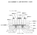
図4はセパレータローラ300の詳細構成図であり、図4(a)は側面図、図4(b)紙葉類の進入側から見た図である。
セパレータローラ300は、同図に示すように、ローラ芯材となるローラカラー301の外周面に、摩擦部材であるゴム輪302を嵌め込んで構成されている。このセパレータローラ300は、繰り出し動作中は回転しないようにロックされ、紙葉類受け入れ時には繰り出しと逆方向(矢印A方向)に図示せぬ駆動手段によって回転駆動される軸303に対して回転自在に嵌め込まれている。
軸303には、弾性部材(コイルバネ)304が巻き付けられており、この弾性部材304の一端は、該軸303の穴304aに嵌め込まれ、もう一端はローラカラー301の側面部の穴304bに嵌め込まれている。
これにより、ローラカラー301は、繰り出しと逆の逆方向(矢印A)に回転するように付勢されている。その回転は、ローラカラー301の側面に立てられたピン305が、軸303に立てられたピン306に当たたることによって停止している。
【0018】
弾性部材304は、進行してきた紙葉類がセパレータローラ300に接触すると、その摩擦によってセパレータローラ300が繰り出し方向に連れ回り(矢印B方向)可能な程度の力に調整されている。
この繰り出し方向(矢印B方向)の、セパレータローラ300の連れ回り可能量は、図5に示す様に、紙葉類先端がセパレータローラに最初に接触する位置から、フィードローラとセパレータローラのオーバーラップ最深部までの回転角度(β度)以下になるよう、ローラカラー301の側面に設けられたピン307によって規制されており、ここではβ≧αを満たすα度で設定されている。
即ち、セパレータローラ300が繰り出し動作で進行してきた紙葉類の摩擦で搬送方向に連れ回りせしめると、ピン307が軸側のピン306に当たり、それ以上回転できなくなる。従って、それ以降は従来例と同様、セパレータローラ300は複数枚の紙葉類の進行にブレーキ力をあたえる摩擦部材として機能する。
【0019】
次に、本実施例による繰り出し機構の動作を説明する。
図1において、ステージ230に積載された紙葉類210の束は、矢印S方向に押圧されており、ピックローラ220の矢印A方向の回転に伴って、積載された紙葉類の上部の数枚が繰り出し方向に進行する。
同時に、フィードローラ240も矢印A方向に駆動回転され、最初は摩擦係数の小さい樹脂面が1枚目の紙葉類211に接触していて搬送力を生じていないが、フィードローラ240の回転に伴ってそのゴム部241が1枚目の紙葉類に搬送力を付与し始める。
従来例と同様に、2枚目212、場合によっては3枚目の紙葉類が、1枚目の紙葉類211の進行に引きずられて、ビルスライダ270に案内されてフィードローラ240とセパレータローラ300のオーバーラップ間に進入してゆく。
【0020】
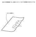
そして、図5の動作詳細説明図に示すように、紙葉類の先端はセパレータローラ300に衝突するが、この時、セパレータローラ300は既述の構成によって紙葉類との摩擦力によって繰り出し方向(矢印B)に連れ回り回転する。
この連れ回り回転によって、紙葉類先端にかかる力が緩和されるとともに、紙葉類先端がセパレータローラ300の接線方向にスムースに向くことができる。
繰り出し動作が進行し、1枚目の紙葉類211、場合によっては2枚目の紙葉類によってセパレータローラ300がα度連れ回されると、図6に示す状態になってセパレータローラ300の連れ回り回転は停止される。
以降、セパレータローラ300は連れ回り回転しないので、紙葉類の進行を阻止するように機能して2枚目以降の紙葉類が停止し、セパレータローラ300より大きい摩擦力を持つフィードローラ240の回転によって、1枚目の紙葉類のみが繰り出されてゆく。
【0021】
1枚目の紙葉類が繰り出された後、2枚目紙葉類先端が引き続きセパレータローラ300に乗り上げているときは、セパレータローラは図6に示した状態、即ちα度、またはその角度以下、回転した状態を保持したままである。
引き続き、2枚目の紙葉類の繰り出し動作が行われる場合は、紙葉類先端は既にセパレータローラの接線方向に向いているので、詰まることは無い。
繰り出し動作が繰り返され、セパレータローラ300に乗り上げている紙葉類が無くなると、弾性部材304の働きによってセパレータローラ300は連れ回りと逆の方向(矢印A)に回転し、図5に示す初期位相に戻る。
以上の動作を繰り返すことにより、コシが無くなったボロボロの紙葉類でも、紙詰まりを起こすことが無い、信頼性の高い繰り出し動作を行うことができる。
【0022】
(付記1) 積層されている紙葉類を、1枚ずつに分離して繰り出す紙葉類繰り出し装置であって、
複数枚の紙葉類が搬送されることを摩擦によって防ぐための円筒形を有する摩擦部材と、
外周の一部が上記円筒形を有する摩擦部材とオーバーラップして配置され、該紙葉類を繰り出すためのフィードローラとを備え、
前記円筒形を有する摩擦部材が、紙葉類の通過に伴って繰り出し方向に連れ回り可能に構成された
ことを特徴とする紙葉類の繰り出し装置。
(付記2) 上記円筒形状を有する摩擦部材の連れ回り量は、紙葉類が該円筒形摩擦部材に最初に接触する位置から、上記オーバーラップの最深部までの回転角度以下になるように構成されている
ことを特徴とする付記1の紙葉類の繰り出し装置。
(付記3)上記円筒形を有する摩擦部材は、それを支持する軸が繰り出し動作を行う前にどの位相で停止しても、紙葉類が該円筒形摩擦部材に最初に接触する位置から、上記オーバーラップの最深部までの回転角度以下になるように構成されたことを特徴とする
ことを特徴とする付記2の紙葉類の繰り出し装置。
(付記4) 上記円筒形状を有する摩擦部材は、弾性部材によって常に繰り出しと逆の方向に回転力を付勢されている
ことを特徴とする付記1,2または付記3の紙葉類の繰り出し装置。
(付記5) 上記弾性部材は、繰り出し動作時には、紙葉類と円筒形状を有する摩擦部材との間の摩擦力によって、該摩擦部材を繰り出し方向に連れ回りさせることのできる弾性定数に設定されている
ことを特徴とする付記4の紙葉類の繰り出し装置。
(付記6) 上記弾性部材は、紙葉類繰り出し後において、紙葉類が該摩擦部材に最初に接触する位置からオーバーラップの最深部までの範囲内に、次に繰り出す紙葉類の先端が存在する場合、
上記円筒形状を有する摩擦部材が、前記紙葉類が該摩擦部材に最初に接触する角度まで戻らない程度の弾性定数に設定されている
ことを特徴とする付記4または付記5の紙葉類の繰り出し装置。
(付記7) 上記円筒形を有する摩擦部材は、繰り出し動作と逆方向に回転駆動された場合に、紙葉類を繰り出しと逆方向に搬送することができるように構成されている
ことを特徴とする付記1,2,3,4,5または付記6の紙葉類の繰り出し装置。
【0023】
【発明の効果】
以上、説明したように、本発明によれば、使い古されてボロボロになり、コシが殆ど無くなったような紙葉類に対しても、紙詰まりを起こすこと無く正確に一枚ずつ繰り出す信頼性の高い紙葉類繰り出し装置を提供することができる。
このため、金融機関等においては、紙幣詰まりが引き起こす現金自動取引装置の休止率を改善して経営効率をアップするとともに、顧客サービスの向上を図ることができ、多大な効果がある。
また印字装置、或いはスキャナ等の自動読み取り装置では、紙詰まり等によって人手を煩わせることがなくなるので事務効率をアップすることができ、経費節減等の効果がある。
【図面の簡単な説明】
【図1】本発明の実施例の紙葉類繰り出し装置の構成を説明する図(側視図)である。
【図2】図1のフィードローラ240とセパレータローラ300の部分を拡大した図である。
【図3】図1を紙葉類の繰り出し方向(排出側)から見た正面図である。
【図4】本発明の実施例のセパレータローラ300詳細構成図である。
【図5】本発明の実施例の動作詳細説明図(セパレータ衝突時)である。
【図6】本発明の実施例の動作詳細説明図(セパレータ分離時)である。
【図7】従来の紙葉類繰り出し装置の概要示す側視図である。
【図8】図7を紙葉類の繰り出し方向(排出側)から見た正面図である。
【図9】従来の紙葉類繰り出し装置の動作説明図(側視図)である。
【図10】従来の紙葉類繰り出し装置の動作説明図(正面図)である。
【図11】従来の紙葉類繰り出し装置における1枚目の紙葉類の変形を示す図である。
【符号の説明】
210 紙葉類
220 ピックローラ
222 軸
221 ゴム部
223 樹脂部
230 ステージ
241 ゴム部
240 フィードローラ
242 樹脂部
243 回転軸
260 側壁
270 ビルスライダ
300 セパレータローラ
301 ローラカラー
302 ゴム輪
303 軸
304 弾性部材(コイルバネ)
304a,304b 穴
305 ピン
306 ピン
307 ピン[0001]
TECHNICAL FIELD OF THE INVENTION
The present invention relates to an automatic teller machine used in financial institutions and the like, a document printing device, or an automatic document reading device such as a scanner, a sheet feeding device in a sheet transport processing device such as a printing device, and in particular, The present invention relates to a sheet feeding device for separating and feeding sheets stacked and stored on a stage or a stacker one by one.
[0002]
[Prior art]
In an automatic teller machine of a financial institution, an automatic document reading device such as a form printing device and a scanner, and a printing device, it is necessary to separate and feed out the sheets stacked on a stage or a stacker one by one.
Conventionally, for example, the following configuration has been used as the paper sheet feeding device.
FIG. 7 is a side view schematically showing a conventional paper sheet feeding device, and FIG. 8 is a front view of FIG. 7 as viewed from the paper sheet feeding direction (discharge side).
In FIG. 7, reference numeral 110 denotes a bundle of paper sheets stacked on a stage 130 which can be pressed in the direction of arrow S, and reference numeral 111 denotes a first paper sheet. Reference numeral 120 denotes a pick roller for advancing the paper sheet in the feeding direction. The pick roller 120 is fixed to a
Reference numeral 150 denotes a separator roller for stopping the advance of the sheets other than the first sheet when a plurality of sheets advance in the feeding direction. It is locked so as not to be entrained by a class, and is supported by a rotating
[0003]
A feed roller 140 is paired with a separator roller 150 to separate and convey paper sheets. The feed roller 140 is attached to a rotating shaft 143 that can be driven in the direction of arrow A, and has a resin portion 142 having a small friction and a large friction. A plurality of
The outer diameter of the
Reference numeral 170 denotes a bill slider arranged so as to sandwich the separator roller 150. This is a guide plate for guiding the leading end of the fed paper sheet to the overlap portion, and has a contact surface with the paper sheet. Are formed to have a smooth state with low friction.
[0004]
Next, the operation of such a feeding device will be described. FIG. 9 is a diagram illustrating a state in which the paper sheets stacked on the stage 130 are being fed.
In FIG. 9, when the pick roller 120 rotates in the direction of arrow A, the first sheet 111 in contact with the feed roller 140 advances in the feeding direction. The second sheet moves in the feeding direction by the frictional force of the first sheet. In some cases, the third sheet moves in the feeding direction while being dragged by the second sheet. At the same time, the feed roller 140 is driven and rotated in the direction of arrow A.
Initially, the outer peripheral surface, which is the resin portion 142 of the feed roller 140, is merely in contact with the first sheet and slips, but as the rotation of the feed roller progresses, the
At this time, since the pick roller 120 is rotated and the outer peripheral surface of the resin portion 123 is in contact with the first sheet, no conveyance force by the pick roller 120 is generated. The pick roller 120 stops in this state, and does not generate a subsequent conveying force.
[0005]
The leading edge of the fed first paper sheet 111 advances along the bill slider 170 and enters between the overlap of the feed roller 140 and the separator roller 150.
FIGS. 10 and 11 show a state in which the sheet 111 has entered between the overlaps. In this state, the portion C in FIG. 11 is pressed by the feed roller 140, and the leading end of the sheet is a separator roller. Since it is pushed up by 150, as shown in FIG. 11, the paper sheet 111 is bent and deformed in a wave shape.
As described above, since the separator roller 150 cannot rotate in the paper sheet feeding direction, it functions as a member that prevents the paper sheet from advancing. At the same time, when the third paper sheet that has entered the overlap comes into contact with the separator roller, the frictional force prevents the third paper sheet from advancing. This is because the frictional force on the third sheet by the separator roller 150 is larger than the advancing force due to the friction between the second sheet and the third sheet.
Even if the second sheet continues to advance due to the frictional force from the first sheet, since the contact surface of the separator roller 150 has an arc shape, the overlap amount gradually increases with the advance of the sheet. As a result, the stopping force of the separator roller 150 is increased due to the frictional force received from the third sheet and the stopping force due to the frictional force of the separator roller 150.
[0006]
The first sheet 111 is prevented from moving by the frictional force of the second sheet and the stopping force by the frictional force of the separator roller 150. Is larger, the paper is transported in the feeding direction.
As the rotation of the feed roller 140 progresses, the outer peripheral portion of the resin portion 142 having low friction comes into contact with the paper sheet, the conveyance force to the paper sheet is lost, and the feed roller 140 stops in that state.
Then, only the first sheet is pulled out and transported by a transport device (not shown). With the above operation, only the first sheet is taken out of the stacked sheets and transported. When feeding out a plurality of sheets, this operation is sequentially repeated for the required number of sheets.
Also, at the time of deposit processing in the automatic teller machine, paper sheets enter in a direction opposite to the payout, so that the separator roller 150 is rotated in the reverse direction to the payout direction to make the separator roller 150 function as a transport roller. .
[0007]
Further, in the above-mentioned sheet feeding device, in order to feed the sheets one by one accurately without causing double feeding or chaining, the overlap amount of the inner feed roller is set in the latter half of the feeding operation. There has been proposed a device in which the overlap amount of the outer feed rollers is made smaller than that of the outside feed rollers (for example, see Patent Document 1).
Among the plurality of feed rollers fixed to the same rotating shaft, the one described in Patent Literature 1 has, for example, the rubber portions of two feed rollers arranged on the inner side are more outward than the rubber portions of the feed rollers. In the latter half of the feeding operation, the rubber portion of the inner feed roller is separated from the paper sheet earlier than the rubber portion of the outer feed roller. Thus, in the latter half of the feeding operation, the overlap amount of the inner feed roller can be made smaller than the overlap amount of the outer feed roller. For this reason, the conveyance force given to the second and subsequent sheets by the first sheet can be reduced, and the progress of the second and subsequent sheets can be reliably prevented by the separator.
[0008]
[Patent Document 1]
JP 2002-19985 A
[0009]
[Problems to be solved by the invention]
Overseas, there are countries and regions in which distribution tickets with worn out and worn-out paper stiffness have almost disappeared, such as those that do not appear in the market in Japan first in Japan. Problems may arise with the use of the conventional feeding device shown.
In other words, when such a circulation ticket enters the payout mechanism, when the leading edge of the paper sheet collides with the rubber surface of the separator roller, it is bent and crushed by friction because there is no stiffness, and paper jam occurs. May be caused. This applies a conveying force to the sheet in a state where the separator roller hinders the advance of the sheet leading edge by pushing the sheet with the feed roller from the rear side slightly away from the sheet leading edge, and there is no stiffness. This is because paper sheets cannot maintain their own shape.
The circulation tickets in Japan are collected and exchanged before they are worn out so that they are almost eliminated, and therefore, the condition is considerably better than those of overseas circulation tickets.
[0010]
In the above-mentioned conventional feeding device, after the leading end of the paper sheet collides with the separator roller, it must change its direction in the tangential direction of the outer peripheral surface of the roller to get over the separator. In the case of a domestic circulation ticket, even if it is pushed out from the feed roller and its tip receives resistance from the separator roller, it sticks with the stiffness of the paper itself, slides on the separator roller while maintaining its own shape, and the tangential line of the separator roller By changing the direction of the tip in the direction, you can get over without causing paper jam.
However, in the case of an overseas circulation ticket with almost no paper stiffness, if the paper is pushed from behind by the feed roller in a state where the paper is in contact with the separator roller and receives resistance, the shape cannot be maintained, and the tip is bent and bent. It is easy to cause crushing and paper jam.
In such an overlap type sheet feeding device, the first sheet is corrugated by the overlap as shown in FIG. 10 and is folded along the separator roller 150 indicated by θ in FIG. , The apparent rigidity at the leading end of the paper sheet increases.
In the case of domestic distribution tickets, even a distribution ticket whose condition is not so good can secure sufficient rigidity and does not cause much problem. However, in the case of an overseas circulation ticket in a poor state, there is a case in which the rigidity of the paper sheet cannot be ensured even if it is three-dimensionally deformed as shown in FIGS. It is becoming.
[0011]
Once the banknotes are jammed and the device is paused, the operator must remove the jammed banknotes and restore it. Obstacles. Further, even in a manned store, the suspension of the ATM causes an extra time for the attendant, and causes the customer to wait until the ATM is restored. As described above, the suspension of the ATM causes a decrease in customer service and management efficiency.
In a printing apparatus and a document reading apparatus, once a paper jam occurs, labor becomes troublesome and a reduction in office efficiency is caused. As described above, in the paper sheet feeding device, if the feeding is not performed accurately without causing the paper jam, a large loss or disadvantage is caused.
[0012]
In order to solve these problems, it is only necessary to reduce the amount of overlap or reduce the friction coefficient of the separator roller so that the load applied to the leading edge of the bill is reduced. Since the force for stopping the movement of the kind is also weakened, double feed, in which two or more sheets are fed out together, is likely to occur.
The risk of double-feeding is higher for paper sheets with normal stiffness (such as government-seal tickets and domestic circulation tickets). Conversely, if the amount of overlap is increased, overseas distribution tickets with weak stiffness are more likely to be clogged, and paper sheets with ordinary stiffness (such as government-sealed tickets and domestic circulation tickets) will have garbled and scratched tips And the risk of non-feeding when the friction coefficient of the feed roller is reduced due to wear or paper dust increases.
In order to prevent the tip of paper leaf having a stiffness such as a government sealed ticket from hitting the separator, the rubber on the surface where the paper leaf tip hits the separator is apparent to prevent the tip of paper leaf from being scraped or scratched. Although a configuration in which the paper is configured to be stiff has been proposed (for example, Japanese Patent Application No. 2000-333651), paper sheets that are worn out and have almost lost rigidity are not assumed.
[0013]
In order to solve these problems, it is considered possible to use a device that determines the paper quality of the paper sheet to be fed and adjusts the amount of overlap dynamically and instantaneously. I will invite you.
Heretofore, there has been no way to solve these problems without increasing costs.
The present invention has been made in view of the above-mentioned drawbacks of the prior art, and the object of the present invention is to provide a wide range of services from a stiff and flexible overseas distribution ticket to a domestic solid government sealed ticket with almost no increase in cost. An object of the present invention is to provide a highly reliable paper sheet feeding device which is compatible with paper sheets having a paper quality and has no paper jam or other feeding obstacles.
[0014]
[Means for Solving the Problems]
In order to solve the above-described problem, in the present invention, in the paper sheet feeding device having the above-described configuration, the separator roller is configured to be rotatable in the feeding direction as the paper sheet passes.
Specifically, as shown in FIG. 4, the separator roller 300 is configured by fitting a rubber ring 302 as a friction member on the outer peripheral surface of a roller collar 301 as a roller core material.
It is locked so as not to rotate during the feeding operation, and is rotatably fitted to a
Further, the amount of rotation is regulated by stopping the pin 305 standing on the side surface of the roller collar against the pin 306 standing on the
The elastic member 304 is adjusted to a force that can be swiveled by the friction of the paper sheets that have advanced, and the amount of swivel of the separator roller 300 in the feeding direction (the direction of arrow B) is shown in FIG. As shown in FIG. 5, the distance from the position where the leading end of the paper sheet first contacts the separator roller to the deepest part of the overlap between the feed roller and the separator roller (β degrees when the rotation center P is set) is set to be less than or equal to It is regulated by a pin 307 provided on the side surface of the roller collar 301.
In other words, when the separator roller 300 rotates in the transport direction and the pin 307 hits the pin 306 on the shaft side, it cannot be further rotated, so that the separator roller 300 exerts a braking force on the advance of a plurality of sheets after that. It functions as a friction member.
Further, after the sheet is fed, the elastic member 304 has a leading edge of the next sheet to be fed within a range from a position where the sheet first contacts the separator roller 300 to a deepest portion of the overlap. In this case, the separator roller 300 is set to have an elastic constant that does not return to an angle at which the paper sheet first contacts the friction member.
In addition, even if the separator roller 300 stops at any phase before the
With these configurations, when the paper sheet comes into contact with the separator roller during the feeding operation and tries to get over the paper sheet, the separator roller 300 is rotated in the transport direction (arrow B) due to the friction of the paper sheet, so that the front end of the paper sheet is smooth. In the direction of the tangential direction of the separator roller 300, even in a used ticket such as an extremely weakly used circulation ticket that normally loses the friction of the separator roller and the tip is crushed to cause a jam, paper jam does not occur. A highly reliable device can be provided with a simple configuration.
It should be noted that even if the leading edge of the paper sheet smoothly enters the overlap portion, the maximum separating force (force to stop the advancement of the paper sheet) is actually applied to the deepest portion of the overlapping sheet, and the leading edge of the paper sheet is there. , And stops as a friction member to apply a braking force to a plurality of sheets, so that paper sheets do not overlap.
Since the present invention is configured as described above, when the paper sheet tip collides with the separator roller and gets over it, in a process in which the rigidity of the paper sheet is most required, the paper sheet is tangential to the separator roller. A highly reliable paper feeder that can smoothly move the front end and reduce the resistance applied to the front end of paper sheets, and can feed out even a battered overseas circulation ticket without weak papers. It can be provided with a simple configuration.
[0015]
BEST MODE FOR CARRYING OUT THE INVENTION
Hereinafter, the configuration of a paper sheet feeding device according to the present invention will be described with reference to the drawings.
FIG. 1 is a side view illustrating a configuration of a paper sheet feeding device according to an embodiment of the present invention, FIG. 2 is an enlarged view of a feed roller 240 and a separator roller 300 shown in FIG. 1, and FIG. FIG. 1 is a front view of the sheet No. 1 as viewed from a sheet feeding direction (discharge side).
1, 2, and 3, except for the separator 300, it has the same configuration as that shown in FIGS. 7 and 8.
1, 2, and 3, reference numeral 210 denotes a bundle of paper sheets stacked on a stage 230 that can be pressed in the direction of arrow S, and reference numeral 211 denotes a first paper sheet.
The pick roller 220 for advancing the paper sheet in the feeding direction is fixed to the shaft 222 rotatable in the direction of arrow A, and includes the resin portion 223 having a small friction and the rubber portion 221 having a large friction as described above. ing.
In addition, a separator roller 300 is provided to prevent advance of the sheets other than the first sheet when a plurality of sheets advance in the feeding direction.
As described later, the separator roller 300 is configured to be able to rotate in the feeding direction with the passage of the paper sheet, and is configured to be able to rotate and drive the separator roller in a direction opposite to the feeding when receiving the bill. I have.
As described above, for the separator roller 300, a material having a value slightly higher than the friction coefficient between paper sheets, such as a rubber material generally having a hardness of about 70 to 80 degrees, is used.
[0016]
Reference numeral 240 denotes a feed roller which is paired with the separator roller 300 and separates and conveys paper sheets. The feed roller 240 is attached to a rotating shaft 243 that can be driven in the direction of arrow A, and has a resin portion 242 having a small friction and a large friction. As shown in FIG. 2, a plurality of rubber portions 241 are arranged coaxially in the same phase.
The outer diameter of the rubber portion 241 is slightly larger than the outer peripheral surface of the resin portion 242 as described above. As described above, the positional relationship between the separator roller 300 and the feed roller 240 is such that a part of the outer peripheral surface of the separator roller 300 projects from the outer peripheral surface of the feed roller 240 and overlaps with the feed roller. The feed roller 240 rotates in the direction of arrow A to feed out the paper sheet.
Further, similarly to the above, a bill slider 270 which is a guide plate for guiding the leading end of the paper sheet to the overlap portion is provided, and a
[0017]
FIG. 4 is a detailed configuration diagram of the separator roller 300. FIG. 4A is a side view, and FIG. 4B is a diagram viewed from the entrance side of the paper sheet.
As shown in the drawing, the separator roller 300 is configured by fitting a rubber ring 302 as a friction member on the outer peripheral surface of a roller collar 301 as a roller core material. The separator roller 300 is locked so as not to rotate during the feeding operation, and is rotatable with respect to a
An elastic member (coil spring) 304 is wound around the
Thereby, the roller collar 301 is urged to rotate in the opposite direction (arrow A) opposite to the feeding. The rotation is stopped by the pin 305 erected on the side surface of the roller collar 301 hitting the pin 306 erected on the
[0018]
The elastic member 304 is adjusted to such a force that the separator roller 300 can rotate in the feeding direction (in the direction of arrow B) due to the friction when the advanced paper sheet comes into contact with the separator roller 300.
The amount of rotation of the separator roller 300 in the feeding direction (the direction of the arrow B) is, as shown in FIG. 5, from the position where the leading edge of the paper sheet first contacts the separator roller, the overlap between the feed roller and the separator roller. The rotation angle (β degrees) to the deepest part is regulated by a pin 307 provided on the side surface of the roller collar 301, and is set to α degrees that satisfies β ≧ α.
That is, when the separator roller 300 is caused to rotate in the transport direction by the friction of the paper sheet that has been advanced by the feeding operation, the pin 307 hits the pin 306 on the shaft side, and cannot be further rotated. Accordingly, thereafter, as in the conventional example, the separator roller 300 functions as a friction member that applies a braking force to the advance of a plurality of sheets.
[0019]
Next, the operation of the feeding mechanism according to the present embodiment will be described.
In FIG. 1, the bundle of paper sheets 210 loaded on the stage 230 is pressed in the direction of arrow S, and the number of paper sheets loaded on the stage 230 increases as the pick roller 220 rotates in the direction of arrow A. The sheet advances in the feeding direction.
At the same time, the feed roller 240 is also driven and rotated in the direction of the arrow A. At first, a resin surface having a small coefficient of friction is in contact with the first sheet 211 to generate no conveying force. Accordingly, the rubber portion 241 starts giving a conveying force to the first sheet.
As in the conventional example, the second sheet 212 and, in some cases, the third sheet are dragged by the advance of the first sheet 211 and guided by the bill slider 270 to feed the feed roller 240 and the separator. It enters between the overlaps of the rollers 300.
[0020]
Then, as shown in the detailed operation diagram of FIG. 5, the leading end of the paper sheet collides with the separator roller 300. At this time, the separator roller 300 is moved in the feeding direction by the frictional force with the paper sheet by the above-described configuration. (The arrow B).
By this co-rotation, the force applied to the leading end of the paper sheet is reduced, and the leading end of the paper sheet can be smoothly directed in the tangential direction of the separator roller 300.
When the feeding operation proceeds and the separator roller 300 is rotated by α degrees by the first sheet 211 and, in some cases, the second sheet, the state shown in FIG. The entrainment rotation is stopped.
Thereafter, since the separator roller 300 does not rotate together with the feed roller 240, the second and subsequent sheets stop so that the paper sheet stops moving, and the feed roller 240 having a frictional force greater than that of the separator roller 300 is stopped. By rotation, only the first sheet is fed out.
[0021]
When the leading edge of the second sheet continues to ride on the separator roller 300 after the first sheet is fed, the separator roller is in the state shown in FIG. , While maintaining the rotated state.
Subsequently, when the feeding operation of the second sheet is performed, the leading end of the sheet is already in the tangential direction of the separator roller, so that the sheet is not jammed.
When the feeding operation is repeated and there are no more paper sheets running on the separator roller 300, the elastic member 304 rotates the separator roller 300 in the direction opposite to the entrainment (arrow A), and the initial phase shown in FIG. Return to
By repeating the above operation, a highly reliable feeding operation that does not cause a paper jam can be performed even on a tattered sheet with no stiffness.
[0022]
(Supplementary Note 1) A sheet feeding device that separates and feeds stacked sheets one by one,
A friction member having a cylindrical shape for preventing a plurality of sheets from being conveyed by friction,
A part of the outer periphery is disposed so as to overlap with the friction member having the cylindrical shape, and a feed roller for feeding out the paper sheet is provided.
The friction member having the cylindrical shape is configured to be rotatable in the feeding direction with the passage of the paper sheet.
A paper sheet feeding device characterized by the above-mentioned.
(Supplementary Note 2) The rotation amount of the friction member having the cylindrical shape is configured to be equal to or less than the rotation angle from the position where the paper sheet first contacts the cylindrical friction member to the deepest portion of the overlap. Have been
A paper sheet feeding device according to claim 1, characterized in that:
(Supplementary Note 3) The friction member having the cylindrical shape, even if the shaft supporting it stops at any phase before performing the feeding operation, from the position where the sheets first contact the cylindrical friction member, It is characterized in that the rotation angle is not more than the rotation angle up to the deepest part of the overlap.
2. The paper sheet feeding device according to claim 2, wherein:
(Supplementary Note 4) The friction member having the cylindrical shape is always urged by an elastic member in a direction opposite to the direction in which the friction member is extended.
The sheet feeding device according to any one of appendices 1, 2 and 3 characterized by the above-mentioned.
(Supplementary Note 5) During the feeding operation, the elastic member is set to have an elastic constant capable of rotating the friction member in the feeding direction by a frictional force between the paper sheet and the friction member having a cylindrical shape. Is
4. The sheet feeding device according to claim 4, wherein
(Supplementary Note 6) After the sheet is fed, the tip of the next sheet to be fed is within a range from the position where the sheet first contacts the friction member to the deepest portion of the overlap. If there,
The friction member having the cylindrical shape is set to an elastic constant that does not return to an angle at which the paper sheet first contacts the friction member.
4. The sheet feeding device according to claim 4 or claim 5, wherein
(Supplementary Note 7) The friction member having a cylindrical shape is configured to be able to convey paper sheets in a direction opposite to the feeding operation when the friction member is rotationally driven in a direction opposite to the feeding operation.
The paper feeding device according to any one of appendices 1, 2, 3, 4, 5 and 6 characterized by the above-mentioned.
[0023]
【The invention's effect】
As described above, according to the present invention, the reliability of accurately feeding out one sheet at a time without causing paper jams even for paper sheets that are worn out and worn out and have almost no stiffness. A high paper sheet feeding device can be provided.
Therefore, in a financial institution or the like, the stoppage rate of the automatic teller machine caused by the banknote jam can be improved to improve the management efficiency, and the customer service can be improved.
In a printing device or an automatic reading device such as a scanner, there is no need for labor due to a paper jam or the like, so that office efficiency can be improved, and there is an effect of reducing costs.
[Brief description of the drawings]
FIG. 1 is a diagram (side view) illustrating a configuration of a paper sheet feeding device according to an embodiment of the present invention.
FIG. 2 is an enlarged view of a part of a feed roller 240 and a separator roller 300 of FIG.
FIG. 3 is a front view of FIG. 1 as viewed from a paper sheet feeding direction (discharge side).
FIG. 4 is a detailed configuration diagram of a separator roller 300 according to the embodiment of the present invention.
FIG. 5 is a detailed explanatory diagram of the operation of the embodiment of the present invention (at the time of collision with a separator).
FIG. 6 is a detailed explanatory diagram of the operation of the embodiment of the present invention (when the separator is separated).
FIG. 7 is a side view schematically showing a conventional paper sheet feeding device.
FIG. 8 is a front view of FIG. 7 as viewed from a sheet feeding direction (discharge side).
FIG. 9 is an operation explanatory view (side view) of a conventional paper sheet feeding device.
FIG. 10 is an operation explanatory view (front view) of a conventional paper sheet feeding device.
FIG. 11 is a diagram showing a deformation of the first sheet in the conventional sheet feeding device.
[Explanation of symbols]
210 Paper
220 Pick roller
222 axes
221 Rubber part
223 resin part
230 stages
241 rubber part
240 feed roller
242 resin part
243 rotation axis
260 Side wall
270 Building Slider
300 separator roller
301 roller color
302 rubber ring
303 axes
304 elastic member (coil spring)
304a, 304b hole
305 pin
306 pin
307 pin
Claims (5)
複数枚の紙葉類が搬送されることを摩擦によって防ぐための円筒形を有する摩擦部材と、
外周の一部が上記円筒形を有する摩擦部材とオーバーラップして配置され、該紙葉類を繰り出すためのフィードローラとを備え、
前記円筒形を有する摩擦部材が、紙葉類の通過に伴って繰り出し方向に連れ回り可能に構成された
ことを特徴とする紙葉類の繰り出し装置。A sheet feeding device that separates and feeds stacked sheets one by one,
A friction member having a cylindrical shape for preventing a plurality of sheets from being conveyed by friction,
A part of the outer periphery is disposed so as to overlap with the friction member having the cylindrical shape, and a feed roller for feeding out the paper sheet is provided.
The paper sheet feeding device, wherein the cylindrical friction member is configured to be rotatable in the feeding direction as the paper sheet passes.
ことを特徴とする請求項1の紙葉類の繰り出し装置。The rotation amount of the friction member having the cylindrical shape is configured to be equal to or less than the rotation angle from the position where the paper sheet first contacts the cylindrical friction member to the deepest portion of the overlap. The paper sheet feeding device according to claim 1, wherein:
ことを特徴とする請求項1の紙葉類の繰り出し装置。The friction member having a cylindrical shape is provided with a structure in which the overlap of the overlapped member is started from a position where the sheet first comes into contact with the cylindrical friction member, even if the shaft supporting the shaft stops at any phase before performing the feeding operation. 2. The sheet feeding device according to claim 1, wherein the rotation angle is equal to or less than the rotation angle up to the deepest portion.
ことを特徴とする請求項1,2または請求項3の紙葉類の繰り出し装置。4. The paper sheet feeding device according to claim 1, wherein said friction member having a cylindrical shape is constantly biased by an elastic member in a direction opposite to the direction in which the friction member is fed.
上記円筒形状を有する摩擦部材が、前記紙葉類が該摩擦部材に最初に接触する角度まで戻らない程度の弾性定数に設定されている
ことを特徴とする請求項4または請求項5の紙葉類の繰り出し装置。The elastic member, after feeding out the paper sheet, in the range from the position where the paper sheet first contacts the friction member to the deepest part of the overlap, when the tip of the next paper sheet to be fed out exists,
6. The paper sheet according to claim 4, wherein the friction member having the cylindrical shape is set to an elastic constant that does not return to an angle at which the paper sheet first contacts the friction member. Kind of feeding device.
Priority Applications (1)
| Application Number | Priority Date | Filing Date | Title |
|---|---|---|---|
| JP2003128762A JP4145191B2 (en) | 2003-05-07 | 2003-05-07 | Paper sheet feeding device |
Applications Claiming Priority (1)
| Application Number | Priority Date | Filing Date | Title |
|---|---|---|---|
| JP2003128762A JP4145191B2 (en) | 2003-05-07 | 2003-05-07 | Paper sheet feeding device |
Publications (2)
| Publication Number | Publication Date |
|---|---|
| JP2004331307A true JP2004331307A (en) | 2004-11-25 |
| JP4145191B2 JP4145191B2 (en) | 2008-09-03 |
Family
ID=33504789
Family Applications (1)
| Application Number | Title | Priority Date | Filing Date |
|---|---|---|---|
| JP2003128762A Expired - Fee Related JP4145191B2 (en) | 2003-05-07 | 2003-05-07 | Paper sheet feeding device |
Country Status (1)
| Country | Link |
|---|---|
| JP (1) | JP4145191B2 (en) |
-
2003
- 2003-05-07 JP JP2003128762A patent/JP4145191B2/en not_active Expired - Fee Related
Also Published As
| Publication number | Publication date |
|---|---|
| JP4145191B2 (en) | 2008-09-03 |
Similar Documents
| Publication | Publication Date | Title |
|---|---|---|
| JP4415002B2 (en) | Paper sheet feeding mechanism | |
| JP3560223B2 (en) | Paper sheet separation and feeding device | |
| US10380821B2 (en) | Temporary paper money storage device | |
| KR20080002509A (en) | Structure for preventing stack roller rotation of atm | |
| JP2001504425A (en) | Sheet feeder | |
| JP4691586B2 (en) | Paper sheet separation mechanism | |
| US20110101598A1 (en) | Method of operating a document feeding mechanism to reduce chance of a document jam condition and an apparatus therefor | |
| JP2007112601A (en) | Paper sheet separation device | |
| JP4415060B2 (en) | Paper sheet feeding mechanism | |
| WO2019073632A1 (en) | Paper sheet separating and transporting device, paper sheet separating and transporting method, and paper sheet handling device | |
| JP2004331307A (en) | Delivery device for paper sheet | |
| JP4968918B2 (en) | Sheet feeding apparatus and image forming apparatus | |
| JPS63282032A (en) | Sheet pay-out device | |
| JP2002019985A (en) | Sheet delivery device | |
| JP2009274773A (en) | Paper sheets feed mechanism, recirculation type bill storing device, bill processor, and bill handling device | |
| JP2010052884A (en) | Paper sheet handling device | |
| JP4040958B2 (en) | Paper sheet feeding device | |
| JPH08151154A (en) | Paper sheet handling device | |
| JP3810884B2 (en) | Paper sheet feeder | |
| JP2001067527A (en) | Paper sheet medium batch feeding device | |
| JP3223641B2 (en) | Paper handling equipment | |
| JP2002179275A (en) | Sheet conveying device | |
| JP2008186314A (en) | Paper sheet feeding device and paper sheet stacking device | |
| JP2001160167A (en) | Circulating type paper sheet stacker unit | |
| JP2002104673A (en) | Sheet sending-out device |
Legal Events
| Date | Code | Title | Description |
|---|---|---|---|
| A621 | Written request for application examination |
Free format text: JAPANESE INTERMEDIATE CODE: A621 Effective date: 20060424 |
|
| A977 | Report on retrieval |
Free format text: JAPANESE INTERMEDIATE CODE: A971007 Effective date: 20080311 |
|
| A131 | Notification of reasons for refusal |
Free format text: JAPANESE INTERMEDIATE CODE: A131 Effective date: 20080318 |
|
| A521 | Written amendment |
Free format text: JAPANESE INTERMEDIATE CODE: A523 Effective date: 20080515 |
|
| TRDD | Decision of grant or rejection written | ||
| A01 | Written decision to grant a patent or to grant a registration (utility model) |
Free format text: JAPANESE INTERMEDIATE CODE: A01 Effective date: 20080617 |
|
| A01 | Written decision to grant a patent or to grant a registration (utility model) |
Free format text: JAPANESE INTERMEDIATE CODE: A01 |
|
| A61 | First payment of annual fees (during grant procedure) |
Free format text: JAPANESE INTERMEDIATE CODE: A61 Effective date: 20080617 |
|
| R150 | Certificate of patent or registration of utility model |
Free format text: JAPANESE INTERMEDIATE CODE: R150 |
|
| FPAY | Renewal fee payment (event date is renewal date of database) |
Free format text: PAYMENT UNTIL: 20110627 Year of fee payment: 3 |
|
| FPAY | Renewal fee payment (event date is renewal date of database) |
Free format text: PAYMENT UNTIL: 20120627 Year of fee payment: 4 |
|
| FPAY | Renewal fee payment (event date is renewal date of database) |
Free format text: PAYMENT UNTIL: 20120627 Year of fee payment: 4 |
|
| FPAY | Renewal fee payment (event date is renewal date of database) |
Free format text: PAYMENT UNTIL: 20130627 Year of fee payment: 5 |
|
| FPAY | Renewal fee payment (event date is renewal date of database) |
Free format text: PAYMENT UNTIL: 20130627 Year of fee payment: 5 |
|
| LAPS | Cancellation because of no payment of annual fees |