JP2004325108A - Instrument for vehicle - Google Patents
Instrument for vehicle Download PDFInfo
- Publication number
- JP2004325108A JP2004325108A JP2003116787A JP2003116787A JP2004325108A JP 2004325108 A JP2004325108 A JP 2004325108A JP 2003116787 A JP2003116787 A JP 2003116787A JP 2003116787 A JP2003116787 A JP 2003116787A JP 2004325108 A JP2004325108 A JP 2004325108A
- Authority
- JP
- Japan
- Prior art keywords
- rotation speed
- speed
- coefficient
- predetermined
- detected
- Prior art date
- Legal status (The legal status is an assumption and is not a legal conclusion. Google has not performed a legal analysis and makes no representation as to the accuracy of the status listed.)
- Pending
Links
- 230000005540 biological transmission Effects 0.000 claims description 38
- 238000001514 detection method Methods 0.000 claims 13
- 238000000034 method Methods 0.000 description 16
- 238000010586 diagram Methods 0.000 description 3
- 230000007935 neutral effect Effects 0.000 description 3
- 230000001133 acceleration Effects 0.000 description 1
- 230000000694 effects Effects 0.000 description 1
- 239000000446 fuel Substances 0.000 description 1
Images
Abstract
Description
【0001】
【発明の属する技術分野】
本発明は、車両の原動機回転数を補正して表示する車両用計器に関する。
【0002】
【従来の技術】
従来、回転数のメモリを表示した文字板と、該文字板上を車両の原動機の回転数にもとづいて回動する指針とを備えた計器(いわゆるタコメータ)が周知である。このようなタコメータの文字板には、原動機の耐久性に影響を及ぼす恐れのある回転数以下の所定の回転数範囲(いわゆるレッドゾーン)が、たとえば赤色の印刷で表示されている。つまり原動機の回転数が高くなり、原動機の耐久性に影響を及ぼす恐れのある回転数(いわゆるオーバーレブ回転数)へ到達する可能性があることを運転者に認識させるために、オーバーレブ回転数から所定の余裕回転数を引いた回転数以上をレッドゾーンとして文字板に表示している。
【0003】
また車両に用いられる自動変速機として、低速域では高い加速を得るために、たとえば1速から2速への変速などの低い変速段(以下ギアポジション)でのシフトアップは原動機回転数が高い領域で行い、一方、高速域では燃費を向上させるために、たとえば2速から3速への変速などの高いギアポジションでのシフトアップは原動機回転数が低い領域で行うなど、シフトアップ回転数がギアポジションによって異なるものがある。
【0004】
【発明が解決しようとする課題】
このような従来のタコメータにあっては、上記のようなシフトアップ回転数がギアポジションによって異なる自動変速機を用いた場合、たとえばタコメータのレッドゾーン開始回転数を1速から2速へのシフトアップ回転数に設定した場合、2速から3速へシフトアップを行うと、タコメータの表示回転数はレッドゾーンの開始回転数よりも低い回転数の位置でシフトアップが行われる。またタコメータのレッドゾーン開始回転数を2速から3速へのシフトアップ回転数に設定した場合、1速から2速へシフトアップを行うと、タコメータ表示回転数はレッドゾーンの開始回転数以上の位置でシフトアップが行われ、運転者に違和感を与えるという問題があった。
【0005】
そこで本発明はこのような問題点に鑑み、ギアポジションによって変速時の回転数が異なる自動変速機を用いた車両においても、運転者に違和感を与えることが無いように原動機の回転数を表示する計器を提供することを目的とする。
【0006】
【課題を解決するための手段】
本発明は、原動機に接続された変速機を介して駆動輪を駆動する車両の、原動機の原動機回転数を補正して表示する車両用計器であって、原動機の原動機回転数Xを検出する回転数検出手段と、変速機の変速段を検出する変速段検出手段と、該変速段検出手段によって検出された変速段と、回転数検出手段によって検出された原動機回転数Xとにもとづいて、原動機回転数Xを補正して表示回転数Yとする表示回転数算出手段とを有し、該表示回転数算出手段によって算出された表示回転数Yを表示するものとした。
【0007】
【発明の効果】
本発明によれば、たとえばレッドゾーン開始回転数を超えないように計器に表示する回転数を設定するなど、表示回転数を自動変速機の変速段と原動機回転数Xとにもとづいて設定することができるので、ギアポジションによって変速時の回転数が異なる自動変速機を搭載した車両の原動機の回転数を表示する際にも、運転者に違和感を与えることが無い。
【0008】
【発明の実施の形態】
次に本発明の実施の形態を実施例により説明する。
まず第一の実施例について説明する。
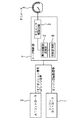
図1に本発明における第一の実施例の構成を示す。
エンジン(不図示)の制御を行うエンジンコントローラ1と、自動変速機(不図示)の変速制御を行うATコントローラ5とがメータ制御部7に接続される。
エンジンコントローラ1は、たとえばエンジンのクランクシャフトに設けられた回転速センサ(不図示)によって検出された回転速度から、エンジンの回転数Xを検出して、メータ制御部7にエンジン回転数信号を出力する。
【0009】
ATコントローラ5は、自動変速機の現在の変速段(ギアポジション)およびATレンジ(パーキングポジションP、リバースポジションR、ニュートラルポジションN、ドライブポジションD、1速レンジ、2速レンジ)を検出し、ギアポジション信号およびATレンジ信号としてメータ制御部7に出力する。
【0010】
メータ制御部7は、エンジンの回転数を表示するタコメータ4が接続されている。
またメータ制御部7は、エンジンコントローラ1から出力されたエンジン回転数信号と、ATコントローラ5から出力されたギアポジション信号およびATレンジ信号と、後述する係数とにもとづいて、タコメータ4に表示する回転数である表示回転数Yを算出し、算出した表示回転数Yにもとづいてタコメータ4の指針を駆動する。
【0011】
次にメータ制御部7の構成について詳述する。
メータ制御部7は、表示回転数演算部2、タコメータ駆動回路3および係数記憶部8から構成されている。
係数記憶部8は、ギアポジションに応じたシフトアップ回転数A(A1、A2、A3)を記憶している。本実施例では、1速(1速から2速へ)のシフトアップ回転数A1を6500rpm、2速(2速から3速へ)のシフトアップ回転数A2を6250rpm、3速(3速から4速へ)のシフトアップ回転数A3を6000rpmとして記憶している。
【0012】
表示回転数演算部2は、あらかじめ定められたレッドゾーン開始回転数R(本実施例では6000rpmとする)を記憶するとともに、ATコントローラ5から出力されたギアポジション信号にもとづいて現在のギアポジションに応じた係数(ここでは係数としてシフトアップ回転数を設定するものとし、シフトアップ回転数A1を係数Z1、同様にシフトアップ回転数A2を、係数Z2とする)を係数記憶部8から読み出し、読み出した係数とエンジンコントローラ1から読み出したエンジン回転数信号とから、タコメータ4に表示する表示回転数を後述する計算式にもとづいて算出し、表示回転数信号としてタコメータ駆動回路3に出力する。
タコメータ駆動回路3は、表示回転数演算部2から出力された表示回転数信号にもとづいてタコメータ4の指針を駆動するモータ(不図示)を制御して、表示回転数Yをタコメータ4に表示する。
【0013】
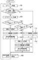
次に図2のフローチャートを用いて、表示回転数演算部2で行われる処理内容について説明する。
なおこの処理は、車両のイグニッションがオンされた後イグニッションがオフされるまでの間繰り返し実行される。
ステップ101において、表示回転数演算部2はATコントローラ5から出力されたATレンジ信号を読み込み、現在の自動変速機のATレンジを判別する。
【0014】
ステップ102において、ステップ101において判別したATレンジがドライブポジションD(D)、2速レンジ(2速)または1速レンジ(1速)のいずれかであるかどうかを判定し、ATレンジがドライブポジションD、2速レンジまたは1速レンジのいずれかである場合には、ステップ103へ進み、そうでない場合、すなわちパーキングポジションP、リバースポジションR、ニュートラルポジションNである場合には、ステップ113へ進む。
【0015】
ステップ103において、ATコントローラ5から出力されたギアポジション信号を読み込む。
ステップ104において、読み込んだギアポジション信号にもとづいて現在の自動変速機のギアポジションが1速であるかどうかを判別し、1速である場合にはステップ105へ進む。また1速で無い場合、すなわちギアポジションが2速、3速または4速である場合にはステップ109へ進む。
【0016】
ステップ105において、ギアポジション1速に対応する係数、すなわち、1速から2速へのシフトアップ回転数A1(係数Z1=6500rpm)を、係数記憶部8から読み出し、ステップ106へ進む。
ステップ106では、エンジンコントローラ1から出力されるエンジンの回転数信号を読み込み、エンジン回転数Xとして取得する。
【0017】
ステップ107において、係数記憶部8から読み出したギアポジション1速に対応する係数A1(6500rpm)と、あらかじめ記憶しているレッドゾーン開始回転数R(6000rpm)とATコントローラ5から取得したエンジン回転数Xとから、次式を用いてタコメータ4に表示する表示回転数Yを算出する。

【0018】
ステップ108では、ステップ107や後述するステップ112、ステップ114において算出された表示回転数Yをタコメータ駆動回路3に出力する。
これによってタコメータ4には、シフトアップ時にもレッドゾーン開始回転数Rを超えないようなエンジン回転数が表示される。
【0019】
一方ステップ109において、現在の自動変速機のギアポジションが2速であるかどうかを判別する。ギアポジションが2速である場合にはステップ110へ進み、そうでない場合、すなわちギアポジションが3速または4速である場合には、ステップ113へ進む。
【0020】
ステップ110では、ギアポジション2速に対応する係数、すなわち、2速から3速へのシフトアップ回転数A2(係数Z2=6250rpm)を、係数記憶部8から読み出し、ステップ111へ進む。
ステップ111では、エンジンコントローラ1から出力されるエンジンの回転数信号を読み込み、エンジン回転数Xとして取得する。
【0021】
ステップ112において、係数記憶部8から読み出したギアポジション2速に対応する係数Z2(6250rpm)と、あらかじめ記憶しているレッドゾーン開始回転数R(6000rpm)とATコントローラ5から取得したエンジン回転数Xとから、上述の式(1)と同様に、次式を用いてタコメータ4に表示する表示回転数Yを算出する。
表示回転数Y=6000/6250×6250=6000rpmとなり、シフトアップ時の表示回転数Yはレッドゾーン開始回転数R(6000rpm)を超えることはない。
【0022】
一方、ステップ102においてATレンジがパーキングポジションP、リバースポジションR、ニュートラルポジションNであると判別された場合、あるいはステップ109においてギアポジションが3速または4速であると判別された場合は、ステップ113においてエンジン回転数Xを読み込む。
【0023】
ステップ114において、エンジン回転数Xを表示回転数Yとして算出し、ステップ108において表示回転数Yをタコメータ駆動回路3に出力する。
これによって、3速から4速へのシフトアップ回転数は6000rpmであるから、シフトアップ時の表示回転数Yはレッドゾーン開始回転数(6000rpm)を超えることはない。
【0024】
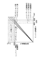
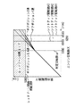
次に図3を用いて、エンジン回転数とタコメータ4に表示される回転数との関係を示す。
自動変速機の現在のギアポジションが1速である場合、上述の式(1)を用いて算出された表示回転数Yにしたがってタコメータ4を駆動するので、自動変速機が1速から2速へシフトアップする際にエンジン回転数Xがシフトアップ回転数A1(6500rpm)となった場合にも、タコメータ4に表示される回転数がレッドゾーン開始回転数R(6000rpm)を超えることがない。
また自動変速機の現在のギアポジションが2速である場合も同様に、上述の式(2)を用いて表示回転数Yを算出することにより、タコメータ4に表示される回転数がレッドゾーン開始回転数R(6000rpm)を超えることがない。
【0025】
さらに自動変速機の現在のギアポジションが3速、4速である場合には、3速から4速へシフトアップする際のシフトアップ回転数A3が6000rpmであるので、タコメータ4に表示される回転数がレッドゾーン開始回転数R(6000rpm)を超えることがない。
なお本実施例において、ステップ106、ステップ111およびステップ113が本発明における回転数検出手段を構成し、ステップ104およびステップ109が本発明における変速段検出手段を構成する。またステップ107、ステップ112およびステップ114が本発明における表示回転数算出手段を構成する。さらに係数記憶部8が本発明における係数記憶手段を構成し、ステップ105およびステップ110が本発明における係数選択手段を構成する。
【0026】
本実施例は以上のように構成され、タコメータ4にエンジン回転数を表示する際に、自動変速機のギアポジションに応じた係数を取得し、式(1)を用いて実際のエンジン回転数に補正を加えて、タコメータ4に補正後のエンジン回転数を表示する。これにより、レッドゾーン開始回転数Rよりもシフトアップ回転数が高回転である場合にも、シフトアップ時にタコメータ4に表示される回転数がレッドゾーン開始回転数を超えることが無くなり、運転者がタコメータ4を視認した際にも違和感を感じることが無い。
【0027】
また自動変速機のシフトアップ回転数を、係数記憶部8に記憶させる係数に設定することにより、各ギアポジションにおいてシフトアップ回転数が異なる場合にも、各ギアポジションにおいてもタコメータ4に表示する回転数がレッドゾーン開始回転数Rを超えることが無い。
【0028】
なお本実施例においては、係数記憶部8に記憶する係数をギアポジションに応じたシフトアップ回転数としたが、レッドゾーン開始回転数Rをギアポジションに応じたシフトアップ回転数A1またはA2で除算した値を記憶するようにしてもよい。つまり、レッドゾーン開始回転数Rとギアポジションに応じたシフトアップ回転数A1またはA2は予め定められた値である事から、レッドゾーン開始回転数R/シフトアップ回転数A1、およびレッドゾーン開始回転数R/シフトアップ回転数A2の値を係数記憶部8に記憶しておき、現在の自動変速機のギアポジションに応じて適宜これらの係数を読み込むようにしてもよい。
これによって表示回転数演算部2の演算負荷を少なくすることができる。
【0029】
次に第二の実施例について説明する。
なお第二の実施例は、上記第一の実施例における表示回転数演算部2での処理内容を変更したものであり、全体構成についての説明を省略する。
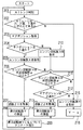
図4のフローチャートを用いて、表示回転数演算部2で行われる処理内容について説明する。なお本実施例におけるステップ201からステップ204は、第一の実施例におけるステップ101からステップ104と同じであるため説明を省略する。
ステップ205において、表示回転数演算部2はエンジンコントローラ1から出力されるエンジン回転数信号を読み込み、エンジン回転数Xとして取得する。
【0030】
ステップ206において、エンジン回転数Xが所定回転数α(本実施例においては5000rpm)以上であるかどうかを判別し、エンジン回転数Xが所定回転数α以上の場合はステップ207へ進み、所定回転数α未満の場合はステップ215へ進む。
ステップ207において、ギアポジション1速に対応する係数Z1(シフトアップ回転数A1=6500rpm)を、係数記憶部8から読み出し、ステップ208へ進む。
【0031】
ステップ208において、係数記憶部8から読み出したギアポジション1速に対応する係数Z1(6500rpm)と、あらかじめ記憶しているレッドゾーン開始回転数R(6000rpm)とATコントローラ5から取得したエンジン回転数Xとから、次式を用いてタコメータ4に表示する表示回転数Yを算出する。
表示回転数Y=(レッドゾーン回転数R−所定回転数α)/(係数Z1−所定回転数α)×(エンジンの回転数X−所定回転数α)+所定回転数α(3)
【0032】
すなわち、エンジン回転数Xが6500rpmである場合、
表示回転数Y=(6000−5000)/(6500−5000)×(6500−5000)+5000=6000rpmであり、シフトアップ時の表示回転数Yはレッドゾーン開始回転数(6000rpm)を超えることは無い。
【0033】
ステップ209では、ステップ208や後述するステップ214、ステップ216において算出された表示回転数Yをタコメータ駆動回路3に出力する。
これによってタコメータ4には、シフトアップ時にもレッドゾーン開始回転数Rを超えないようなエンジン回転数が表示される
【0034】
一方、ステップ204にて現在の自動変速機のギアポジションが1速ではないと判別された場合、すなわちギアポジションが2速、3速、4速のいずれかである場合にはステップ210へ進み、エンジンコントローラ1から出力されるエンジンの回転数信号を読み込み、エンジン回転数Xとして取得する。
【0035】
ステップ211において、取得したエンジン回転数Xが所定回転数α以上であるかどうかを判別し、エンジン回転数Xが所定回転数α以上であればステップ212へ進む。エンジン回転数が所定回転数α未満の場合にはステップ215へ進む。
【0036】
ステップ212において、現在の自動変速機のギアポジションが2速であるかどうかを判別する。ギアポジションが2速である場合にはステップ213へ進み、そうでない場合、すなわちギアポジションが3速または4速である場合には、ステップ215へ進む。
【0037】
ステップ213において、ギアポジション2速に対応する係数、すなわち、2速から3速へのシフトアップ回転数A2(係数Z2=6250rpm)を、係数記憶部8から読み出し、ステップ214へ進む。
【0038】
ステップ214において、係数記憶部8から読み出したギアポジション2速に対応する係数Z2(6250rpm)と、あらかじめ記憶しているレッドゾーン開始回転数R(6000rpm)とATコントローラ5から取得したエンジン回転数Xとから、上述の式(3)と同様に、次式を用いてタコメータ4に表示する表示回転数Yを算出する。
表示回転数Y=(レッドゾーン開始回転数R−所定回転数α)/(係数Z2−所定回転数α)×(エンジンの回転数X−所定回転数α)+所定回転数α(4)
【0039】
すなわち、エンジン回転数Xが6250rpmである場合、
表示回転数Y=(6000−5000)/(6250−5000)×(6250−5000)+5000=6000rpmとなり、シフトアップ時の表示回転数Yはレッドゾーン開始回転数(6000rpm)を超えることはない。
【0040】
一方、ステップ215において、エンジンコントローラ1から出力されるエンジンの回転数信号を読み込み、エンジン回転数Xとして取得する。
ステップ216において、エンジン回転数Xを表示回転数Yとしてタコメータ駆動回路3へ出力し、ステップ209において表示回転数Yをタコメータに表示する。3速から4速へのシフトアップ回転数A3は6000rpmであるので、シフトアップ時の表示回転数Yはレッドゾーン開始回転数(6000rpm)を超えることはない。
【0041】
次に図5を用いて、エンジン回転数とタコメータ4に表示される回転数との関係を示す。
自動変速機の現在のギアポジションが1速である場合、エンジン回転数Xが所定回転数αとなるまでは、エンジン回転数Xを表示回転数Yとして設定するが、エンジン回転数Xが所定回転数α(5000rpm)以上となった場合には、上述の式(3)を用いて算出された表示回転数Yにしたがってタコメータ4を駆動するので、自動変速機が1速から2速へシフトアップする際にシフトアップ回転数A1(6500rpm)となった場合にも、タコメータ4に表示される回転数がレッドゾーン開始回転数R(6000rpm)を超えることがない。
【0042】
また自動変速機の現在のギアポジションが2速である場合も同様に、エンジン回転数Xが所定回転数α以上となった場合には、上述の式(4)を用いて表示回転数Yを算出することにより、タコメータ4に表示される回転数がレッドゾーン開始回転数R(6000rpm)を超えることがない。
さらに自動変速機の現在のギアポジションが3速、4速である場合には、3速から4速へシフトアップする際のシフトアップ回転数A3が6000rpmであるので、タコメータ4に表示される回転数がレッドゾーン開始回転数R(6000rpm)を超えることがない。
【0043】
なお本実施例において、ステップ205、ステップ210およびステップ215が本発明における回転数検出手段を構成し、ステップ204およびステップ212が本発明における変速段検出手段を構成する。またステップ208、ステップ214およびステップ216が本発明における表示回転数算出手段を構成する。さらに係数記憶部8が本発明における係数記憶手段を構成し、ステップ207およびステップ213が本発明における係数選択手段を構成する。
【0044】
本実施例は以上のように構成され、エンジン回転数Xが所定回転数α以上となった場合にのみ、エンジン回転数Xと各ギアポジションに対応する係数Z1およびZ2(シフトアップ回転数A1およびA2)と、所定回転数αと、予め定められたレッドゾーン開始回転数Rとにもとづいて表示回転数Yを算出する。これにより、エンジン回転数Xが所定回転数α未満の場合にはエンジン回転数Xを表示回転数Yとする事ができ、表示回転数演算部2の演算負荷を軽減しつつ、エンジン回転数が所定回転数以上の場合にも、タコメータ4に表示される回転数がレッドゾーン開始回転数Rを超えることが無い。
【0045】
なお本実施例において、係数記憶部8に記憶する係数をギアポジションに応じたシフトアップ回転数としたが、レッドゾーン回転数Rから所定回転数αを減算した値を、各ギアポジションに応じたシフトアップ回転数A1またはA2から所定回転数αを減算した値で除算した値を記憶するようにしてもよい。
すなわち、レッドゾーン回転数Rと各ギアポジションに応じたシフトアップ回転数A1またはA2、および所定回転数αはあらかじめ定められた値である事から、(R−α)/(A1−α)および(R−α)/(A2−α)の値を係数記憶部8に記憶しておき、自動変速機の現在の各ギアポジションに応じてこれらの係数を読み込むようにしてもよい。
【0046】
また上記各実施例における自動変速機が、運転者が任意にギアチェンジが可能なマニュアルモード付きの自動変速機である場合にも、自動変速機がマニュアルモードの1速、2速の状態の時に、上記の各実施例に示した1速レンジ、2速レンジの時と同じ処理を行いタコメータ4を駆動することにより、エンジン回転数が所定回転数以上の場合にも、タコメータ4に表示される回転数がレッドゾーン開始回転数Rを超えることが無い。
さらに上記各実施例において、自動変速機の変速段は4段として説明したが、変速段数はこれに限定されるものではなく、さらにギアポジションが1速および2速の時にのみエンジン回転数Xの補正を行うものとしたが、適宜表示回転数の補正を行うギアポジションを設定することができる。
【図面の簡単な説明】
【図1】本発明における第一の実施例を示す図である。
【図2】表示回転数演算部で行う処理の流れを示すフローチャートである。
【図3】エンジン回転数と表示回転数との関係を示す図である。
【図4】表示回転数演算部で行う処理の流れを示すフローチャートである。
【図5】エンジン回転数と表示回転数との関係を示す図である。
【符号の説明】
1 エンジンコントローラ
2 表示回転数演算部
3 タコメータ駆動回路
4 タコメータ
5 ATコントローラ
7 メータ制御部
8 係数記憶部[0001]
TECHNICAL FIELD OF THE INVENTION
The present invention relates to a vehicle instrument for correcting and displaying a rotation speed of a motor of a vehicle.
[0002]
[Prior art]
2. Description of the Related Art Conventionally, an instrument (a so-called tachometer) provided with a dial displaying a memory of a rotation speed and a pointer that rotates on the dial based on the rotation speed of a motor of a vehicle is known. On the dial of such a tachometer, a predetermined rotation speed range (a so-called red zone) lower than the rotation speed that may affect the durability of the prime mover is displayed by, for example, red printing. That is, in order to make the driver aware that the rotation speed of the prime mover may increase and reach a rotation speed (so-called overrev rotation speed) that may affect the durability of the prime mover, a predetermined value is set based on the overrev rotation speed. The number of revolutions equal to or less than the marginal number of revolutions is displayed on the dial as a red zone.
[0003]
As an automatic transmission used in a vehicle, in order to obtain high acceleration in a low speed range, upshifting in a low gear (hereinafter referred to as a gear position) such as a shift from a first speed to a second speed is performed in a region where the prime mover speed is high. On the other hand, in order to improve fuel efficiency in the high-speed range, upshifting in a high gear position, such as shifting from second gear to third gear, is performed in a region where the rotation speed of the prime mover is low. Some are different depending on the position.
[0004]
[Problems to be solved by the invention]
In such a conventional tachometer, when an automatic transmission in which the above-described upshift speed differs depending on the gear position is used, for example, the tachometer red zone start speed is shifted from the first speed to the second speed. In the case where the rotation speed is set, when shifting up from the second speed to the third speed is performed, the display rotation speed of the tachometer is shifted up at a position where the rotation speed is lower than the start rotation speed of the red zone. Also, when the tachometer red zone start rotation speed is set to the upshift rotation speed from the second speed to the third speed, if the upshift from the first speed to the second speed is performed, the tachometer display rotation speed is equal to or more than the start rotation speed of the red zone. There has been a problem that the upshift is performed at the position, which gives the driver an uncomfortable feeling.
[0005]
In view of the above problems, the present invention displays the rotational speed of the prime mover so that the driver does not feel uncomfortable even in a vehicle using an automatic transmission whose rotational speed varies depending on the gear position. It is intended to provide an instrument.
[0006]
[Means for Solving the Problems]
The present invention relates to a vehicle instrument for correcting and displaying a prime mover rotational speed of a prime mover of a vehicle that drives driving wheels via a transmission connected to the prime mover, wherein the rotational speed detects a prime mover rotational speed X of the prime mover. A speed detecting means for detecting a speed of the transmission; a speed detecting means for detecting a speed of the transmission; a motor speed based on a speed X detected by the speed detecting means; Display rotation speed calculating means for correcting the rotation speed X to obtain the display rotation speed Y, and displaying the display rotation speed Y calculated by the display rotation speed calculation device.
[0007]
【The invention's effect】
According to the present invention, the display speed is set based on the gear position of the automatic transmission and the motor speed X, for example, by setting the speed displayed on the instrument so as not to exceed the red zone start speed. Therefore, when displaying the rotation speed of the motor of a vehicle equipped with an automatic transmission having a different rotation speed at the time of shifting depending on the gear position, the driver does not feel uncomfortable.
[0008]
BEST MODE FOR CARRYING OUT THE INVENTION
Next, embodiments of the present invention will be described with reference to examples.
First, a first embodiment will be described.
FIG. 1 shows the configuration of the first embodiment of the present invention.
An engine controller 1 that controls an engine (not shown) and an
The engine controller 1 detects an engine speed X from a speed detected by a speed sensor (not shown) provided on a crankshaft of the engine, for example, and outputs an engine speed signal to the meter control unit 7. I do.
[0009]
The
[0010]
The tachometer 4 for displaying the number of revolutions of the engine is connected to the meter control unit 7.
The meter control unit 7 also controls the rotation displayed on the tachometer 4 based on the engine speed signal output from the engine controller 1, the gear position signal and the AT range signal output from the
[0011]
Next, the configuration of the meter control unit 7 will be described in detail.
The meter control unit 7 includes a display rotation
The
[0012]
The display rotation
The
[0013]
Next, the contents of processing performed by the display rotation
Note that this process is repeatedly executed after the ignition of the vehicle is turned on until the ignition is turned off.
In
[0014]
In
[0015]
In
In
[0016]
In step 105, the coefficient corresponding to the first gear position, that is, the upshift rotation speed A1 from the first gear to the second gear (coefficient Z1 = 6500 rpm) is read from the
In step 106, an engine speed signal output from the engine controller 1 is read and acquired as an engine speed X.
[0017]
In
[0018]
In
As a result, the tachometer 4 displays an engine speed that does not exceed the red zone start speed R even when upshifting.
[0019]
On the other hand, in
[0020]
In
In
[0021]
In
The display rotation speed Y = 6000/6250 × 6250 = 6000 rpm, and the display rotation speed Y at the time of shift-up does not exceed the red zone start rotation speed R (6000 rpm).
[0022]
On the other hand, if it is determined in
[0023]
In
As a result, the shift-up rotation speed from the third speed to the fourth speed is 6000 rpm, so that the display rotation speed Y at the time of shift-up does not exceed the red zone start rotation speed (6000 rpm).
[0024]
Next, the relationship between the engine speed and the speed displayed on the tachometer 4 will be described with reference to FIG.
When the current gear position of the automatic transmission is the first speed, the tachometer 4 is driven in accordance with the display rotation speed Y calculated using the above equation (1), so that the automatic transmission shifts from the first speed to the second speed. Even when the engine speed X becomes the upshift speed A1 (6500 rpm) when upshifting, the speed displayed on the tachometer 4 does not exceed the red zone start speed R (6000 rpm).
Similarly, when the current gear position of the automatic transmission is the second speed, the display speed Y is calculated by using the above-described equation (2), so that the rotation speed displayed on the tachometer 4 starts the red zone. It does not exceed the rotation speed R (6000 rpm).
[0025]
Further, when the current gear position of the automatic transmission is the third speed and the fourth speed, the upshift rotation speed A3 at the time of shifting up from the third speed to the fourth speed is 6000 rpm. The number does not exceed the red zone start rotational speed R (6000 rpm).
In this embodiment, steps 106, 111, and 113 constitute a rotation speed detecting means in the present invention, and steps 104 and 109 constitute a gear position detecting means in the present invention.
[0026]
The present embodiment is configured as described above. When displaying the engine speed on the tachometer 4, a coefficient corresponding to the gear position of the automatic transmission is obtained, and the actual engine speed is calculated using the equation (1). After the correction, the tachometer 4 displays the corrected engine speed. As a result, even when the upshift speed is higher than the red zone start speed R, the speed displayed on the tachometer 4 during the upshift does not exceed the red zone start speed, and the driver is not instructed. Even when the tachometer 4 is visually recognized, no uncomfortable feeling is felt.
[0027]
Also, by setting the shift-up rotation speed of the automatic transmission to a coefficient to be stored in the
[0028]
In this embodiment, the coefficient stored in the
As a result, the calculation load on the display rotation
[0029]
Next, a second embodiment will be described.
In the second embodiment, the processing performed by the display rotation
With reference to the flowchart of FIG. 4, the processing performed by the display rotation
In
[0030]
In
In step 207, a coefficient Z1 (shift-up rotation speed A1 = 6500 rpm) corresponding to the first gear position is read from the
[0031]
In
Display rotational speed Y = (Red zone rotational speed R−predetermined rotational speed α) / (coefficient Z1−predetermined rotational speed α) × (engine rotational speed X−predetermined rotational speed α) + predetermined rotational speed α (3)
[0032]
That is, when the engine speed X is 6500 rpm,
Display rotation speed Y = (6000-5000) / (6500-5000) × (6500-5000) + 5000 = 6000 rpm, and the display rotation speed Y at the time of shift-up does not exceed the red zone start rotation speed (6000 rpm). .
[0033]
In
As a result, the tachometer 4 displays an engine speed that does not exceed the red zone start speed R even when upshifting.
On the other hand, if it is determined in
[0035]
In
[0036]
In
[0037]
In
[0038]
In step 214, the coefficient Z2 (6250 rpm) corresponding to the second gear position read from the
Display speed Y = (Red zone start speed R-predetermined speed α) / (coefficient Z2−predetermined speed α) × (engine speed X−predetermined speed α) + predetermined speed α (4)
[0039]
That is, when the engine speed X is 6250 rpm,
The display rotation speed Y = (6000-5000) / (6250-5000) × (6250-5000) + 5000 = 6000 rpm, and the display rotation speed Y at the time of shift-up does not exceed the red zone start rotation speed (6000 rpm).
[0040]
On the other hand, in
At
[0041]
Next, the relationship between the engine speed and the speed displayed on the tachometer 4 will be described with reference to FIG.
When the current gear position of the automatic transmission is the first speed, the engine speed X is set as the display speed Y until the engine speed X reaches the predetermined speed α, but the engine speed X is changed to the predetermined speed. If the number α (5000 rpm) or more is reached, the tachometer 4 is driven according to the display rotational speed Y calculated using the above equation (3), so that the automatic transmission shifts up from the first gear to the second gear. In this case, the speed displayed on the tachometer 4 does not exceed the red zone start rotation speed R (6000 rpm) even when the upshift speed A1 (6500 rpm) is reached.
[0042]
Similarly, when the current gear position of the automatic transmission is the second speed, if the engine speed X is equal to or higher than the predetermined speed α, the display speed Y is calculated using the above-described equation (4). By calculating, the rotation speed displayed on the tachometer 4 does not exceed the red zone start rotation speed R (6000 rpm).
Further, when the current gear position of the automatic transmission is the third speed and the fourth speed, the upshift rotation speed A3 at the time of shifting up from the third speed to the fourth speed is 6000 rpm. The number does not exceed the red zone start rotational speed R (6000 rpm).
[0043]
In this embodiment, steps 205, 210, and 215 constitute the rotation speed detecting means of the present invention, and steps 204 and 212 constitute the gear position detecting means of the present invention.
[0044]
The present embodiment is configured as described above, and only when the engine speed X becomes equal to or higher than the predetermined speed α, the coefficients Z1 and Z2 (the shift-up speeds A1 and A2) corresponding to the engine speed X and each gear position. A2), the predetermined rotation speed α, and the predetermined red zone start rotation speed R, the display rotation speed Y is calculated. As a result, when the engine speed X is less than the predetermined speed α, the engine speed X can be used as the display speed Y, and the engine speed can be reduced while reducing the calculation load of the
[0045]
In the present embodiment, the coefficient stored in the
That is, since the red zone rotation speed R, the upshift rotation speed A1 or A2 according to each gear position, and the predetermined rotation speed α are predetermined values, (R−α) / (A1−α) and The value of (R-α) / (A2-α) may be stored in the
[0046]
Also, in the case where the automatic transmission in each of the above embodiments is an automatic transmission with a manual mode in which the driver can arbitrarily change gears, when the automatic transmission is in the first speed and the second speed in the manual mode. By driving the tachometer 4 by performing the same processing as in the case of the first speed range and the second speed range described in each of the above embodiments, the tachometer 4 is displayed even when the engine speed is equal to or higher than the predetermined speed. The rotation speed does not exceed the red zone start rotation speed R.
Further, in each of the above embodiments, the shift speed of the automatic transmission has been described as four, but the number of shift speeds is not limited to this, and only when the gear position is the first speed and the second speed, the engine speed X Although the correction is performed, a gear position for correcting the display rotation speed can be appropriately set.
[Brief description of the drawings]
FIG. 1 is a diagram showing a first embodiment of the present invention.
FIG. 2 is a flowchart illustrating a flow of a process performed by a display rotation speed calculation unit.
FIG. 3 is a diagram showing a relationship between an engine speed and a display speed.
FIG. 4 is a flowchart illustrating a flow of a process performed by a display rotation speed calculation unit.
FIG. 5 is a diagram showing a relationship between an engine speed and a display speed.
[Explanation of symbols]
DESCRIPTION OF SYMBOLS 1
Claims (9)
前記原動機の原動機回転数Xを検出する回転数検出手段と、
前記変速機の変速段を検出する変速段検出手段と、
該変速段検出手段によって検出された変速段と、前記回転数検出手段によって検出された原動機回転数Xとにもとづいて、前記原動機回転数Xを補正して表示回転数Yとする表示回転数算出手段とを有し、
該表示回転数算出手段によって算出された表示回転数Yを表示する車両用計器。A vehicle instrument for driving a driving wheel via a transmission connected to a prime mover, for correcting and displaying the prime mover rotation speed of the prime mover,
Rotation number detecting means for detecting a motor rotation number X of the motor;
Speed-gear detecting means for detecting the speed of the transmission;
A display rotation speed calculation unit that corrects the rotation speed of the prime mover based on the shift speed detected by the shift speed detection unit and the rotation speed of the prime mover detected by the rotation speed detection unit to obtain a display rotation speed Y; Means,
A vehicle instrument for displaying the display rotation speed Y calculated by the display rotation speed calculation means.
前記変速段検出手段によって検出された変速段にもとづいて、前記係数記憶手段に記憶された係数を選択する係数選択手段とを備え、
前記表示回転数算出手段は、前記回転数検出手段によって検出された原動機回転数Xと前記係数選択手段によって選択された係数とにもとづいて、前記原動機回転数Xを補正することを特徴とする請求項1記載の車両用計器。Coefficient storage means for storing a plurality of coefficients in advance corresponding to the gears of the transmission;
A coefficient selection unit that selects a coefficient stored in the coefficient storage unit based on the gear position detected by the gear position detection unit,
The display rotational speed calculating means corrects the prime mover rotational speed X based on a prime mover rotational speed X detected by the rotational speed detecting means and a coefficient selected by the coefficient selecting means. Item 4. The vehicle meter according to Item 1.
前記係数記憶手段に記憶された係数は、前記変速機の変速段に対応したあらかじめ定められた回転数Aであって、
前記表示回転数演算手段は、前記回転数検出手段によって検出された原動機回転数Xに、レッドゾーン開始回転数Rを前記係数選択手段によって選択された前記回転数Aで除算した値を乗算することによって前記原動機回転数Xを補正することを特徴とする請求項1または2記載の車両用計器。The red zone start rotation speed of the instrument is R,
The coefficient stored in the coefficient storage means is a predetermined rotation speed A corresponding to a shift speed of the transmission,
The display rotation speed calculation means multiplies the prime mover rotation speed X detected by the rotation speed detection means by a value obtained by dividing a red zone start rotation speed R by the rotation speed A selected by the coefficient selection means. 3. The vehicle instrument according to claim 1, wherein the motor rotation speed X is corrected by the following.
前記係数記憶手段に記憶された係数は、前記レッドゾーン開始回転数Rを、前記変速機の変速段に対応したあらかじめ定められた回転数Aで除算した値R/Aであって、
前記表示回転数算出手段は、前記回転数検出手段によって検出された原動機回転数Xに、前記係数選択手段によって選択された係数を乗算することによって前記原動機回転数Xを補正することを特徴とする請求項1または2記載の車両用計器。The red zone start rotation speed of the instrument is R,
The coefficient stored in the coefficient storage means is a value R / A obtained by dividing the red zone start rotational speed R by a predetermined rotational speed A corresponding to a shift speed of the transmission.
The display rotation speed calculation means corrects the motor rotation speed X by multiplying the motor rotation speed X detected by the rotation speed detection means by a coefficient selected by the coefficient selection means. The vehicle instrument according to claim 1.
前記回転数検出手段によって検出された前記原動機回転数Xが所定回転数α未満である場合には、前記回転数検出手段によって検出された原動機回転数Xを前記表示回転数Yとして算出し、
前記回転数検出手段によって検出された原動機回転数Xが所定回転数α以上である場合には、前記回転数検出手段によって検出された原動機回転数Xを補正することを特徴とする請求項1、2、3または4のいずれか1に記載の車両用計器。The display rotation speed calculation means,
When the motor rotation speed X detected by the rotation speed detection means is less than a predetermined rotation speed α, the motor rotation speed X detected by the rotation speed detection means is calculated as the display rotation speed Y,
The motor rotation speed X detected by the rotation speed detection means is corrected when the motor rotation speed X detected by the rotation speed detection means is equal to or greater than a predetermined rotation speed α. The vehicle instrument according to any one of 2, 3, or 4.
前記回転数検出手段によって検出された原動機回転数Xが所定回転数α以上である場合には、レッドゾーン開始回転数Rと前記所定回転数αとの差を、前記回転数Aと前記所定回転数αとの差で除算した値に、
前記回転数検出手段によって検出された原動機回転数Xと前記所定回転数αとの差を乗算した値(R−α)/(A−α)×(X−α)に、前記所定回転数αを加算することによって前記原動機回転数Xを補正することを特徴とする請求項6記載の車両用計器。The coefficient stored in the coefficient storage means is a predetermined rotation speed A corresponding to a shift speed of the transmission,
When the prime mover rotational speed X detected by the rotational speed detecting means is equal to or greater than a predetermined rotational speed α, the difference between the red zone start rotational speed R and the predetermined rotational speed α is determined by comparing the rotational speed A with the predetermined rotational speed α. To the value divided by the difference from the number α,
The value (R−α) / (A−α) × (X−α) obtained by multiplying the difference between the prime mover rotational speed X detected by the rotational speed detecting means and the predetermined rotational speed α is added to the predetermined rotational speed α. The vehicle instrument according to claim 6, wherein the motor rotation speed X is corrected by adding the following.
前記回転数検出手段によって検出された原動機回転数Xが前記所定回転数α以上である場合には、前記係数選択手段によって選択された係数に、前記回転数検出手段によって検出された原動機回転数Xと前記所定回転数αとの差を乗算した値(R−α)/(A−α)×(X−α)に、前記所定回転数αを加算することによって前記原動機回転数Xを補正することを特徴とする請求項6記載の車両用計器。The coefficient stored in the coefficient storage means is a value (R-α) obtained by dividing the difference between the red zone start rotation speed R and the predetermined rotation speed α by the difference between the rotation speed A and the predetermined rotation speed α. / (A-α),
When the motor rotation speed X detected by the rotation speed detection means is equal to or greater than the predetermined rotation speed α, the motor selected by the coefficient selection means includes the motor rotation speed X detected by the rotation speed detection means. The motor rotation speed X is corrected by adding the predetermined rotation speed α to a value (R−α) / (A−α) × (X−α) obtained by multiplying the difference between the rotation speed X and the predetermined rotation speed α. 7. The vehicle instrument according to claim 6, wherein:
Priority Applications (1)
| Application Number | Priority Date | Filing Date | Title |
|---|---|---|---|
| JP2003116787A JP2004325108A (en) | 2003-04-22 | 2003-04-22 | Instrument for vehicle |
Applications Claiming Priority (1)
| Application Number | Priority Date | Filing Date | Title |
|---|---|---|---|
| JP2003116787A JP2004325108A (en) | 2003-04-22 | 2003-04-22 | Instrument for vehicle |
Publications (1)
| Publication Number | Publication Date |
|---|---|
| JP2004325108A true JP2004325108A (en) | 2004-11-18 |
Family
ID=33496886
Family Applications (1)
| Application Number | Title | Priority Date | Filing Date |
|---|---|---|---|
| JP2003116787A Pending JP2004325108A (en) | 2003-04-22 | 2003-04-22 | Instrument for vehicle |
Country Status (1)
| Country | Link |
|---|---|
| JP (1) | JP2004325108A (en) |
Cited By (7)
| Publication number | Priority date | Publication date | Assignee | Title |
|---|---|---|---|---|
| JP2009220678A (en) * | 2008-03-14 | 2009-10-01 | Fuji Heavy Ind Ltd | Engine speed display device |
| KR100933189B1 (en) | 2005-05-16 | 2009-12-22 | 엘지전자 주식회사 | Vacuum cleaner |
| JP2015160592A (en) * | 2014-02-28 | 2015-09-07 | マツダ株式会社 | Vehicular engine speed indicator and engine speed display method for the same |
| CN105522927A (en) * | 2014-10-17 | 2016-04-27 | 现代自动车株式会社 | Cluster control system of vehicle and method thereof |
| KR20160066130A (en) * | 2014-12-01 | 2016-06-10 | 현대자동차주식회사 | Apparatus for displaying engine RPM |
| EP3351416A4 (en) * | 2015-09-16 | 2018-07-25 | Nissan Motor Co., Ltd. | Rotational speed display device |
| US10175143B2 (en) | 2016-03-18 | 2019-01-08 | Toyota Jidosha Kabushiki Kaisha | Display of a meter during an upshift |
-
2003
- 2003-04-22 JP JP2003116787A patent/JP2004325108A/en active Pending
Cited By (12)
| Publication number | Priority date | Publication date | Assignee | Title |
|---|---|---|---|---|
| KR100933189B1 (en) | 2005-05-16 | 2009-12-22 | 엘지전자 주식회사 | Vacuum cleaner |
| JP2009220678A (en) * | 2008-03-14 | 2009-10-01 | Fuji Heavy Ind Ltd | Engine speed display device |
| JP2015160592A (en) * | 2014-02-28 | 2015-09-07 | マツダ株式会社 | Vehicular engine speed indicator and engine speed display method for the same |
| CN105522927A (en) * | 2014-10-17 | 2016-04-27 | 现代自动车株式会社 | Cluster control system of vehicle and method thereof |
| KR101619244B1 (en) | 2014-10-17 | 2016-05-10 | 현대자동차 주식회사 | Cluster control system of vehicle and method thereof |
| US9975428B2 (en) | 2014-10-17 | 2018-05-22 | Hyundai Motor Company | Cluster control system of vehicle and method thereof |
| CN105522927B (en) * | 2014-10-17 | 2019-07-23 | 现代自动车株式会社 | The instrument disk control system and its control method of vehicle |
| KR20160066130A (en) * | 2014-12-01 | 2016-06-10 | 현대자동차주식회사 | Apparatus for displaying engine RPM |
| KR101637754B1 (en) * | 2014-12-01 | 2016-07-08 | 현대자동차주식회사 | Apparatus for displaying engine RPM |
| US9701317B2 (en) | 2014-12-01 | 2017-07-11 | Hyundai Motor Company | Apparatus for displaying engine RPM |
| EP3351416A4 (en) * | 2015-09-16 | 2018-07-25 | Nissan Motor Co., Ltd. | Rotational speed display device |
| US10175143B2 (en) | 2016-03-18 | 2019-01-08 | Toyota Jidosha Kabushiki Kaisha | Display of a meter during an upshift |
Similar Documents
| Publication | Publication Date | Title |
|---|---|---|
| JP5005586B2 (en) | Engine speed display device | |
| JP6008047B2 (en) | Vehicle engine speed display device and control method for vehicle engine speed display device | |
| JP5915377B2 (en) | Automatic transmission control method and automatic transmission system | |
| JP4748254B2 (en) | Fuel-saving driving recommendation device | |
| JP2016060460A (en) | Meter display control unit | |
| JP6350595B2 (en) | Meter display control device | |
| JP2004325108A (en) | Instrument for vehicle | |
| JP2002195087A (en) | Engine control device of automobile | |
| GB2535700A (en) | A method for reducing the amount of fuel used by an engine of a motor vehicle | |
| JP4979981B2 (en) | Vehicle driving force control device | |
| JP3832241B2 (en) | Vehicle driving force control device | |
| US10604014B1 (en) | Tachometer display system and method for display | |
| JP2021151168A (en) | Virtual shift control device of electric vehicle | |
| JP6086040B2 (en) | Vehicle engine speed display device and control method for vehicle engine speed display device | |
| JP5696570B2 (en) | Shift instruction control device | |
| JP4275133B2 (en) | Vehicle display device | |
| JP2006153556A (en) | Rev counter | |
| JP5677824B2 (en) | Control device for automatic transmission | |
| JP6206649B2 (en) | Vehicle engine speed display device and control method for vehicle engine speed display device | |
| JP2005090610A (en) | Control device for continuously variable transmission for vehicle | |
| JP4694414B2 (en) | Vehicle driving force control device | |
| KR100461415B1 (en) | a device and the method for display of shift gears in manual transmission | |
| JP6086041B2 (en) | Vehicle engine speed display device and control method for vehicle engine speed display device | |
| CN107727876B (en) | Predictive tachometer module and method of generating a predictive tachometer curve | |
| JP5968006B2 (en) | Vehicle control device |
Legal Events
| Date | Code | Title | Description |
|---|---|---|---|
| A621 | Written request for application examination |
Free format text: JAPANESE INTERMEDIATE CODE: A621 Effective date: 20060224 |
|
| A977 | Report on retrieval |
Free format text: JAPANESE INTERMEDIATE CODE: A971007 Effective date: 20080619 |
|
| A131 | Notification of reasons for refusal |
Free format text: JAPANESE INTERMEDIATE CODE: A131 Effective date: 20080812 |
|
| A02 | Decision of refusal |
Free format text: JAPANESE INTERMEDIATE CODE: A02 Effective date: 20081209 |