JP2004316632A - Fuel feeder - Google Patents
Fuel feeder Download PDFInfo
- Publication number
- JP2004316632A JP2004316632A JP2003324870A JP2003324870A JP2004316632A JP 2004316632 A JP2004316632 A JP 2004316632A JP 2003324870 A JP2003324870 A JP 2003324870A JP 2003324870 A JP2003324870 A JP 2003324870A JP 2004316632 A JP2004316632 A JP 2004316632A
- Authority
- JP
- Japan
- Prior art keywords
- tank
- fuel
- sub
- supply device
- fuel supply
- Prior art date
- Legal status (The legal status is an assumption and is not a legal conclusion. Google has not performed a legal analysis and makes no representation as to the accuracy of the status listed.)
- Granted
Links
- 239000000446 fuel Substances 0.000 title claims abstract description 120
- 239000002828 fuel tank Substances 0.000 claims abstract description 102
- 238000005192 partition Methods 0.000 claims description 7
- 239000007788 liquid Substances 0.000 claims description 4
- 230000015556 catabolic process Effects 0.000 abstract 1
- 238000006731 degradation reaction Methods 0.000 abstract 1
- 230000007423 decrease Effects 0.000 description 3
- 238000000034 method Methods 0.000 description 3
- 230000002093 peripheral effect Effects 0.000 description 3
- 238000001514 detection method Methods 0.000 description 2
- 238000009434 installation Methods 0.000 description 2
- 230000000994 depressogenic effect Effects 0.000 description 1
- 238000010586 diagram Methods 0.000 description 1
Images
Classifications
-
- Y—GENERAL TAGGING OF NEW TECHNOLOGICAL DEVELOPMENTS; GENERAL TAGGING OF CROSS-SECTIONAL TECHNOLOGIES SPANNING OVER SEVERAL SECTIONS OF THE IPC; TECHNICAL SUBJECTS COVERED BY FORMER USPC CROSS-REFERENCE ART COLLECTIONS [XRACs] AND DIGESTS
- Y02—TECHNOLOGIES OR APPLICATIONS FOR MITIGATION OR ADAPTATION AGAINST CLIMATE CHANGE
- Y02T—CLIMATE CHANGE MITIGATION TECHNOLOGIES RELATED TO TRANSPORTATION
- Y02T10/00—Road transport of goods or passengers
- Y02T10/10—Internal combustion engine [ICE] based vehicles
- Y02T10/12—Improving ICE efficiencies
Landscapes
- Cooling, Air Intake And Gas Exhaust, And Fuel Tank Arrangements In Propulsion Units (AREA)
Abstract
Description
本発明は、エンジンに燃料を供給する燃料供給装置に関する。 The present invention relates to a fuel supply device that supplies fuel to an engine.
サブタンク内に燃料タンク内の燃料を供給することにより、燃料タンク内の燃料が減少しても、サブタンク内に収容された燃料ポンプによりサブタンク内の燃料を吸引し吐出する燃料供給装置が知られている(特許文献1参照)。また、複数の構成部品をシェル内に収容し、1つの穴から燃料タンク内に取り付けられる燃料供給装置が知られている(特許文献2参照)。 A fuel supply device that sucks and discharges fuel in a sub-tank by a fuel pump housed in the sub-tank even when the fuel in the fuel tank is reduced by supplying the fuel in the fuel tank into the sub-tank has been known. (See Patent Document 1). Further, there is known a fuel supply device in which a plurality of components are housed in a shell and mounted in a fuel tank through one hole (see Patent Document 2).
しかしながら、特許文献1に開示されている燃料供給装置の場合、サブタンクが例えばジェットポンプの導入部などのように径方向外側へ突出する突出部を有する場合がある。この場合、サブタンクを燃料タンクの内部に設置するとき、突出部は開口部を有する燃料タンクと干渉しやすい。また、特許文献2に示されるような燃料供給装置でも、シェルが突出部を有する場合は同様の問題が生じる。突出部と燃料タンクとが干渉すると、燃料タンクの内部へのサブタンクの設置は困難となり、工数の増加を招く。一方、突出部と燃料タンクとの干渉を防止するため、サブタンクの突出部に応じて燃料タンクの開口部を拡大することも考えられる。しかし、燃料タンクの開口部を拡大すると、燃料タンクの強度の低下を招くとともに、燃料タンクと燃料供給装置との間のシール部の全長が長くなる。そのため、燃料あるいは燃料タンクの内部で気化した燃料の漏れを招きやすいという問題がある。 However, in the case of the fuel supply device disclosed in Patent Literature 1, the sub-tank may have a protruding portion that protrudes radially outward, such as an introduction portion of a jet pump. In this case, when the sub-tank is installed inside the fuel tank, the protruding portion easily interferes with the fuel tank having the opening. Further, even in a fuel supply device as disclosed in Patent Document 2, a similar problem occurs when the shell has a protruding portion. If the protrusion and the fuel tank interfere with each other, it becomes difficult to install the sub-tank inside the fuel tank, resulting in an increase in man-hours. On the other hand, in order to prevent interference between the protrusion and the fuel tank, it is conceivable to enlarge the opening of the fuel tank in accordance with the protrusion of the sub tank. However, if the opening of the fuel tank is enlarged, the strength of the fuel tank is reduced, and the entire length of the seal between the fuel tank and the fuel supply device is increased. Therefore, there is a problem that leakage of fuel or fuel vaporized inside the fuel tank is likely to occur.
そこで、本発明の目的は、燃料タンクの開口部の大型化を招くことなく、燃料タンクの内部へのサブタンクの設置が容易な燃料供給装置を提供することにある。 Therefore, an object of the present invention is to provide a fuel supply device in which a sub-tank can be easily installed inside a fuel tank without increasing the size of the opening of the fuel tank.
請求項1記載の発明では、サブタンクは突出部の径方向反対側に隅部を有している。隅部はサブタンクの径方向内側へ凹んでいる。そのため、サブタンクは突出部の径方向反対側に形成される隅部によって容易に開口部へ挿入される。すなわち、燃料タンクの内部にサブタンクを収容する場合、まずサブタンクの突出部を開口部側へ傾け突出部を開口部から燃料タンクの内部に挿入する。そして、サブタンクの傾きを戻しながらサブタンクの隅部を燃料タンクの内部に挿入する。このとき、サブタンクに隅部を形成することにより、サブタンクと燃料タンクの開口部とは干渉しない。したがって、開口部を大型化することなく、燃料タンクの内部へサブタンクを容易かつ円滑に設置することができる。また、開口部の大型化を招かないため、燃料タンクの強度の低下を防止することができる。さらに、開口部の大型化にともなうシール長の延長を招かない。したがって、燃料あるいは燃料蒸気の燃料タンクの外部への流出の防止を容易に図ることができる。 According to the first aspect of the invention, the sub-tank has a corner on the side opposite to the protrusion in the radial direction. The corner is recessed radially inward of the sub tank. Therefore, the sub tank is easily inserted into the opening by the corner formed on the radially opposite side of the protrusion. That is, when storing the sub-tank inside the fuel tank, first, the protrusion of the sub-tank is inclined toward the opening, and the protrusion is inserted into the fuel tank from the opening. Then, the corner of the sub tank is inserted into the fuel tank while the inclination of the sub tank is being returned. At this time, by forming a corner in the sub tank, the sub tank and the opening of the fuel tank do not interfere with each other. Therefore, the sub-tank can be easily and smoothly installed inside the fuel tank without increasing the size of the opening. Further, since the size of the opening is not increased, a decrease in the strength of the fuel tank can be prevented. Furthermore, the extension of the seal length due to the enlargement of the opening does not occur. Therefore, it is possible to easily prevent the fuel or the fuel vapor from flowing out of the fuel tank.
請求項2記載の発明では、隅部は曲面状に形成されている。そのため、突出部を燃料タンクの内部に挿入した後、サブタンクを回転させることにより、曲面状の隅部と開口部との干渉が低減される。したがって、燃料タンクの内部へサブタンクを容易に設置することができる。
請求項3記載の発明では、突出部はジェットポンプの導入部である。導入部は、サブタンクから径方向外側へ突出している。そのため、サブタンクにジェットポンプの導入部を設置する場合でも、燃料タンクの内部へサブタンクを容易に設置することができる。
According to the second aspect of the present invention, the corner is formed in a curved shape. Therefore, the interference between the curved corner and the opening is reduced by rotating the sub-tank after inserting the protrusion into the fuel tank. Therefore, the sub-tank can be easily installed inside the fuel tank.
According to the third aspect of the present invention, the projecting portion is an introduction portion of the jet pump. The introduction portion projects radially outward from the sub tank. Therefore, even when the introduction part of the jet pump is installed in the sub tank, the sub tank can be easily installed inside the fuel tank.
請求項4記載の発明では、ジェットポンプは燃料ポンプが収容されるサブタンクの主室部と隔壁により仕切られた副室部に収容されている。例えば、エンジン停止中に、副室部の燃料が燃料タンクに逆流し副室部の燃料が空になる場合でも、主室部と副室部とは仕切られているので、主室部の燃料は燃料タンクに逆流しない。そのため、エンジン停止中においても主室部には燃料が充満されている。したがって、エンジンの始動時、燃料ポンプは主室部の燃料を吸引し速やかに吐出することができる。
請求項5記載の発明では、突出部は検出手段のアーム部およびフロート部である。アーム部およびフロート部は、サブタンクから径方向外側へ突出している。そのため、サブタンクに検出手段のアーム部およびフロート部を設置する場合でも、燃料タンクの内部へサブタンクを容易に設置することができる。
According to the fourth aspect of the present invention, the jet pump is housed in the sub-chamber section divided by the partition from the main chamber section of the sub-tank in which the fuel pump is housed. For example, even when the fuel in the sub-chamber flows back to the fuel tank and the fuel in the sub-chamber is emptied while the engine is stopped, the main chamber and the sub-chamber are separated from each other. Does not flow back into the fuel tank. Therefore, even when the engine is stopped, the main chamber is filled with fuel. Therefore, when the engine is started, the fuel pump can suck the fuel in the main chamber and quickly discharge it.
In the invention described in claim 5, the protruding portions are the arm portion and the float portion of the detecting means. The arm and the float protrude radially outward from the sub tank. Therefore, even when the arm portion and the float portion of the detection means are installed in the sub tank, the sub tank can be easily installed inside the fuel tank.
請求項6記載の発明では、サブタンクは支持部材を支持するサブタンクの支持部を有している。支持部は、例えばサブタンクの側部、またはサブタンクの反底部側を塞ぐ蓋部材と一体に設置されている。そのため、サブタンクは開口部を塞ぐ蓋部材に対し蓋部材の軸方向へ往復移動可能となる。例えば、サブタンクと蓋部材とを支持部材で支持した状態でサブタンクを燃料タンクの底部へ押し付けることにより、燃料タンクの内部の燃料の残量に応じてサブタンクの位置は調整される。したがって、燃料タンクの内部の燃料の残量にかかわらず、燃料タンクの外部へ燃料を吐出することができる。
請求項7記載の発明では、支持部はサブタンクの側部よりも径方向内側に設置されている。そのため、支持部および支持部材はサブタンクの径方向外側へ突出しない。これにより、支持部材によりサブタンクと蓋部材とを支持する場合でも、サブタンクの投影面積は変化しない。その結果、開口部を大型化する必要がない。
In the invention according to claim 6, the sub-tank has a support portion of the sub-tank for supporting the support member. The support portion is provided integrally with, for example, a lid member that closes a side portion of the sub tank or a side opposite to the bottom of the sub tank. Therefore, the sub-tank can reciprocate in the axial direction of the lid member with respect to the lid member closing the opening. For example, by pressing the sub-tank against the bottom of the fuel tank while the sub-tank and the lid member are supported by the support member, the position of the sub-tank is adjusted according to the remaining amount of fuel inside the fuel tank. Therefore, fuel can be discharged to the outside of the fuel tank regardless of the remaining amount of fuel inside the fuel tank.
In the invention according to claim 7, the support portion is installed radially inward of the side portion of the sub tank. Therefore, the support portion and the support member do not protrude outward in the radial direction of the sub tank. Thus, even when the support member supports the sub tank and the lid member, the projected area of the sub tank does not change. As a result, there is no need to increase the size of the opening.
請求項8記載の発明では、支持部材はサブタンクの切欠部に設置されている。切欠部はサブタンクの側部から径方向内側へ凹んでいる。そのため、支持部はサブタンクの径方向外側へ突出しない。これにより、支持部材によりサブタンクと蓋部材とを支持する場合でも、サブタンクの投影面積は変化しない。その結果、開口部を大型化する必要がない。
請求項9記載の発明では、切欠部の蓋部材と反対側の端部は底部の径方向外側に開口している。サブタンクの径方向内側に支持部を設置する場合、サブタンクに隅部を形成すると、支持部材の反蓋部材側の端部とサブタンクの隅部とが接触しやすくなる。そのため、支持部材の移動が制限され、蓋部材とサブタンクとの間の相対的な移動距離が低減される。そこで、請求項9記載の発明では、サブタンクの径方向内側へ凹んだ切欠部に支持部を設置するとともに、切欠部の反蓋部材側の端部が底部の径方向外側に開口している。これにより、サブタンクに隅部を形成する場合でも、支持部材の反蓋部材側の端部がサブタンクの隅部に接触することはない。したがって、蓋部材とサブタンクとの間の移動距離を十分に確保することができる。
In the invention described in claim 8, the support member is provided in the notch of the sub tank. The notch is recessed radially inward from the side of the sub tank. Therefore, the support portion does not protrude outward in the radial direction of the sub tank. Thus, even when the support member supports the sub tank and the lid member, the projected area of the sub tank does not change. As a result, there is no need to increase the size of the opening.
According to the ninth aspect of the present invention, the end of the notch opposite to the lid member opens radially outward of the bottom. In the case where the support portion is installed on the radially inner side of the sub-tank, if the corner portion is formed in the sub-tank, the end portion of the support member on the side opposite to the lid member and the corner portion of the sub-tank are easily contacted. Therefore, the movement of the support member is restricted, and the relative movement distance between the lid member and the sub tank is reduced. In view of this, in the invention according to claim 9, the support portion is provided in the notch recessed inward in the radial direction of the sub tank, and the end of the notch on the side opposite to the lid member opens radially outward of the bottom. Thus, even when a corner is formed in the sub tank, the end of the support member on the side opposite to the lid member does not contact the corner of the sub tank. Therefore, the moving distance between the lid member and the sub tank can be sufficiently ensured.
(第1実施形態)
本発明の第1実施形態による燃料供給装置を図1に示す。
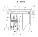
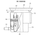
燃料供給装置10は蓋部材としてのフランジ20、サブタンク30、図示しないポンプモジュール、プレッシャレギュレータ、ならびにサクションフィルタなどを備えている。フランジ20は、燃料タンク11の上壁に形成される開口部12を覆っている。サブタンク30は燃料タンク11内に収容されている。燃料タンク11は図示しないドライブシャフトを避ける凹部を有する鞍型に形成されている。燃料タンク11は、サブタンク30を収容している一方のタンク部と移送用ジェットポンプ50により燃料がサブタンク30に移送される他方のタンク部とを有している。
(1st Embodiment)
FIG. 1 shows a fuel supply device according to a first embodiment of the present invention.
The
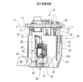
フランジ20は円盤状であり、径方向の両端部に圧入部21を有している。圧入部21には、支持部材としてのシャフト22の一方の端部が圧入されている。シャフト22の他端は、図2に示すようにサブタンク30に形成されている支持部31に緩く挿入されている。サブタンク30は底部32および側部33を有するほぼ円筒状に形成されている。支持部31は、サブタンク30の側部33から径方向内側へ円弧状に凹んだ切欠部34に形成されている。サブタンク30の切欠部34に支持部31を設置することにより、支持部31ならびに支持部31に挿入されるシャフト22はサブタンク30から径方向外側に突出していない。
The
切欠部34は、サブタンク30の側部33の周方向の一部において径方向内側に凹んで形成されている。切欠部34は、サブタンク30の軸方向へ伸びて形成されている。第1実施形態の場合、切欠部34は、サブタンク30の径方向において概ね両端部にそれぞれ一か所ずつ設置されている。サブタンク30は、径方向内側に凹んでいる切欠部34に支持部31を有している。支持部31は、筒状に形成されており、内周側に穴部35を有している。穴部35は、内径がシャフト22の外径よりもやや大きく形成されている。これにより、支持部31は、シャフト22を往復移動可能に支持する。
The
図1に示すように、スプリング23は、一方の端部がフランジ20に接し、他方の端部がサブタンク30に接しており、フランジ20とサブタンク30とが互いに離れる方向に荷重を加えている。これにより、燃料供給装置10を収容する燃料タンク11が温度変化による内圧の変化や燃料量の変化によって膨張または収縮しても、サブタンク30の底部32はスプリング23の押し付け力により燃料タンク11の底部に常に押し付けられる。
サブタンク30の内側は隔壁36により主室部41と副室部42とに区画されている。主室部41には図示しないポンプモジュール、プレッシャレギュレータおよびサクションフィルタが収容される。副室部42には移送用ジェットポンプ50が収容される。突出部としての導入部51は、隔壁36とともに副室部42を形成するサブタンク30の側部33から径方向外側に突出している。導入部51は副室部42に連通している。導入部51には図示しない燃料移送管が取り付けられる。燃料移送管は、反導入部側の端部が燃料タンク11の他方のタンク部へ伸びている。
As shown in FIG. 1, the
The inside of the
図2に示すように、吸引用ジェットポンプ60はサブタンク30の外側に取り付けられている。吸引用ジェットポンプ60は、燃料供給装置10が設置されている燃料タンク11の一方のタンク部内からサブタンク30内へ燃料を供給する。図示しない燃料ポンプで加圧された燃料が流れる昇圧部の途中から取り出された燃料は、吸引用ジェットポンプ60に供給される。吸引用ジェットポンプ60に供給された燃料は、サブタンク30に形成されている吸入口61へ向けて噴射される。吸引用ジェットポンプ60から吸入口61へ向けて高圧の燃料を噴射することにより、サブタンク30の吸入口61側には吸引圧が生じる。これにより、燃料タンク11の一方のタンク部内の燃料はサブタンク30の主室部41内へ吸入される。その結果、燃料タンク11の一方のタンク部内の燃料の液面が低下しても、サブタンク30の主室部41の内部は燃料によって充満される。なお、プレッシャレギュレータから排出される余剰燃料、またはエンジン側からリターンされる余剰燃料を吸引用ジェットポンプ60へ供給し、余剰燃料を吸引用ジェットポンプ60から吸入口61へ向けて噴出する構成としても良い。
As shown in FIG. 2, the
移送用ジェットポンプ50は、副室部42内に取り付けられている。移送用ジェットポンプ50はサブタンク30の副室部42に燃料タンク11の他のタンク部から燃料を移送する。図示しない燃料ポンプの昇圧部の途中から取り出された燃料は移送用ジェットポンプ50に供給される。供給された燃料を移送用ジェットポンプ50から噴射することにより、燃料タンク11の他のタンク部内の燃料は導入部51を経由してサブタンク30の副室部42に吸入される。副室部42に吸入された燃料が副室部42に充満すると、副室部42の燃料は隔壁36を乗り越えて主室部41にあふれ出る。これにより、主室部41は副室部42からあふれ出る燃料により充満される。
The
サブタンク30は、側部33の底部32側に径方向内側へ凹んでいる隅部37を有している。隅部37は、サブタンク30から突出する導入部51の径方向において反対側に形成されている。隅部37は、サブタンク30の周方向において半周程度にわたって形成されている。隅部37は、曲面状に形成されている。隅部37は、図1に示すようにサブタンク30の中心軸を含む平面で切断したとき、断面が例えば二次曲線、三次以上の多次曲線、円弧状の曲線、楕円曲線、指数曲線あるいはトロコイド曲線など任意の曲線状とすることができる。第1実施形態の場合、隅部37の曲面の中心あるいは焦点は、サブタンク30の内側に位置する。そのため、第1実施形態の場合、隅部37はサブタンク30の径方向外側へ膨らんだ曲面状に形成されている。
The sub-tank 30 has a
次に、上述の燃料供給装置10を燃料タンク11に設置する方法について説明する。
シャフト22によりフランジ20と一体に組み付けられたサブタンク30は、燃料タンク11の上壁に形成された開口部12から燃料タンク11の内部に設置される。燃料タンク11の開口部12は、内径がフランジ20の外径よりも小さく形成されている。また、サブタンク30は、外径が開口部12の内径よりもやや小さく形成されている。そのため、サブタンク30は開口部12を通過するものの、フランジ20は開口部12を通過しない。
Next, a method for installing the above-described
The sub-tank 30 integrated with the
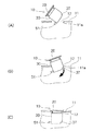
サブタンク30を燃料タンク11の内部に設置する場合、図3(A)に示すようにまず燃料供給装置10を傾け、サブタンク30から突出する導入部51を開口部12に挿入する。導入部51を開口部12に挿入すると、図3(B)に示すように開口部12から燃料供給装置10のサブタンク30を燃料タンク11の内部へ挿入する。そして、燃料供給装置10の傾きを戻しながらサブタンク30の隅部37を燃料タンク11の内部へ挿入しつつ燃料供給装置10を回転させる。これにより、フランジ20は上方へ位置し、サブタンク30は下方へ位置する。このとき、サブタンク30は隅部37を有しているため、燃料供給装置10を回転させても、サブタンク30の隅部37は開口部12を形成する燃料タンク11の内周壁11aに接触しない。そのため、サブタンク30と燃料タンク11とが干渉することなく、サブタンク30は燃料タンク11の内部に収容される。サブタンク30が燃料タンク11内に収容されると、図3(C)に示すように開口部12はフランジ20により塞がれる。フランジ20を燃料タンク11に固定することにより、燃料供給装置10の取り付けは完了する。
When the sub-tank 30 is installed inside the
本発明の第1実施形態では、サブタンク30に隅部37を形成している。これにより、サブタンク30から径方向外側に導入部51などが突出する場合でも、燃料供給装置10を燃料タンク11の内部に収容する際に導入部51と燃料タンク11とが干渉することがない。また、導入部51と燃料タンク11との干渉が防止されるため、サブタンク30から突出する導入部51にあわせて開口部12を拡大する必要はない。したがって、開口部12の大型化を招くことなく、サブタンク30を燃料タンク11の内部へ容易かつ円滑に設置することができる。また、開口部12の大型化を招かないため、燃料タンク11の強度の低下が防止される。さらに、開口部12の大型化にともなってシール長は延長されない。したがって、液密および気密性を高めることができ、燃料あるいは燃料蒸気の燃料タンク11の外部への漏れを容易に防止することができる。
In the first embodiment of the present invention, the
本発明の第1実施形態では、燃料タンク11への燃料供給装置10の設置は、導入部51の挿入、燃料供給装置10の回転、ならびにフランジ20の固定という簡単な工程で実施される。したがって、燃料タンク11を燃料供給装置10へ設置するための工数を低減することができる。
また、本発明の第1実施形態では、サブタンク30の内部は隔壁36により主室部41と副室部42とに仕切られている。そのため、例えばエンジンを停止することにより、副室部42に蓄えられた燃料が燃料タンク11に逆流し副室部42が空になる場合でも、主室部41に蓄えられている燃料は燃料タンク11へ逆流しない。これにより、エンジン停止中であっても、主室部41は燃料で満たされている。したがって、エンジンの始動時、燃料ポンプは主室部41の燃料を吸引し、速やかに吐出することができる。
さらに、本発明の第1実施形態では、シャフト22はサブタンク30の支持部31に支持されている。支持部31は、サブタンク30の側部33よりも径方向内側に凹んだ切欠部34に設置されている。そのため、支持部31、ならびに支持部31に支持されるシャフト22は、サブタンク30の径方向外側へ突出しない。したがって、サブタンク30の投影面積は低減され、サブタンク30を挿入するための開口部12を拡大する必要がない。
In the first embodiment of the present invention, the installation of the
In the first embodiment of the present invention, the inside of the sub-tank 30 is partitioned into a
Further, in the first embodiment of the present invention, the
(第2、3実施形態)
本発明による第2実施形態および第3実施形態をそれぞれ図4または図5に示す。なお、第1実施形態と実質的に同一の部位には同一の符号を付し、説明を省略する。
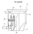
図4に示す第2実施形態では、サブタンク70の隅部71の形状が第1実施形態と異なる。第2実施形態では、隅部71は、曲面状に形成されているものの、曲面の中心あるいは焦点はサブタンク70の外側に位置する。そのため、隅部71は、サブタンク30の径方向内側へ窪んだ曲面状に形成されている。
第2実施形態では、サブタンク70の隅部71は第1実施形態と比較してより径方向内側へ凹んでいる。そのため、導入部51などサブタンク70から突出する部材の突出量が大きいときでも、サブタンク70と燃料タンク11との干渉が防止される。したがって、開口部12の大型化を招くことなく、燃料タンク11の内部へサブタンク70を容易かつ円滑に設置することができる。
(Second and third embodiments)
FIGS. 4 and 5 show a second embodiment and a third embodiment according to the present invention, respectively. Note that the same reference numerals are given to substantially the same portions as those in the first embodiment, and description thereof will be omitted.
In the second embodiment shown in FIG. 4, the shape of the
In the second embodiment, the
図5に示す第3実施形態では、サブタンク72の隅部73の形状が第1実施形態と異なる。第3実施形態では、隅部73は、サブタンク72の中心軸を含む平面で切断したとき、断面が複数の平面を接続した階段状に形成されている。第3実施形態の場合、隅部73は、サブタンク72の径方向内側へ凹んだ階段状に形成されている。
第3実施形態では、サブタンク72の隅部73は第1実施形態と比較して一部がより径方向内側へ凹んでいる。そのため、導入部51などサブタンク72から突出する部材の突出量が大きいときでも、サブタンク72と燃料タンク11との干渉が防止される。したがって、開口部12の大型化を招くことなく、燃料タンク11の内部へサブタンク72を容易かつ円滑に設置することができる。
In the third embodiment shown in FIG. 5, the shape of the
In the third embodiment, a part of the
(第4実施形態)
本発明の第4実施形態による燃料供給装置を図6に示す。なお、第1実施形態と実質的に同一の構成部位には同一の符号を付し、説明を省略する。
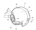
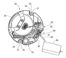
第4実施形態では、図6に示すように燃料供給装置10は検出手段としてのセンダゲージ80を備えている。センダゲージ80は、燃料タンク11の内部における燃料の残量を検出する。センダゲージ80は、パターン部81、支持部82、アーム部83およびフロート部84を有している。パターン部81は、サブタンク30の周方向の一部に形成されている平面状の段差部38に設置されている。パターン部81は、抵抗値の異なる複数の電気抵抗が形成されている回路パターンを有している。支持部82は、アーム部83の一方の端部を支持しており、アーム部83とともにパターン部81に対し相対的に回転可能である。支持部82には図示しない接触部が設置されており、接触部はパターン部81の回路パターンと接触する。アーム部83の他方の端部にはフロート部84が設置されている。フロート部84は、燃料タンク11に蓄えられている燃料に浮遊する。
(Fourth embodiment)
FIG. 6 shows a fuel supply device according to a fourth embodiment of the present invention. The same components as those in the first embodiment are denoted by the same reference numerals, and description thereof is omitted.
In the fourth embodiment, as shown in FIG. 6, the
燃料に浮遊するフロート部84は燃料タンク11に蓄えられている燃料の液面に応じて燃料タンク11の内部を上下に移動する。フロート部84を支持するアーム部83は支持部82により回転可能に支持されているため、フロート部84の上下にともなって支持部82は正方向または逆方向へ回転する。これにより、支持部82の接触部とパターン部81の回路パターンとの接触状態が変化する。その結果、パターン部81で検出される抵抗値が変化し、検出された抵抗値に基づいて燃料タンク11の内部における燃料の液面位置が検出される。
センダゲージ80のアーム部83およびフロート部84は、図7に示すようにサブタンク30の径方向外側に突出している。すなわち、第4実施形態では、アーム部83およびフロート部84がサブタンク30から突出する突出部を構成する。
The
The
第4実施形態による燃料供給装置10を燃料タンク11に設置する場合、まず燃料供給装置10を傾け、サブタンク30から突出するセンダゲージ80のアーム部83およびフロート部84を開口部12に挿入する。アーム部83およびフロート部84を開口部12に挿入すると、開口部12から燃料供給装置10のサブタンク30を燃料タンク11の内部へ挿入する。そして、燃料供給装置10の傾きを戻しながらサブタンク30の隅部37を燃料タンク11の内部へ挿入しつつ燃料供給装置10を回転させる。これにより、フランジ20は開口部12を塞ぐ上方へ位置し、サブタンク30は下方へ位置する。このとき、サブタンク30は隅部37を有しているため、燃料供給装置10を回転させても、サブタンク30の隅部37に対応する位置は開口部12を形成する燃料タンク11の内周壁に接触しない。そのため、サブタンク30と燃料タンク11とが干渉することなく、サブタンク30は燃料タンク11の内部に収容される。サブタンク30が燃料タンク11内に収容されると、開口部12はフランジ20により塞がれる。フランジ20を燃料タンク11に固定することにより、燃料供給装置10の取り付けは完了する。
When the
また、第4実施形態では、サブタンク30の切欠部34は少なくとも一つが隅部37に対応する位置に配置されている。隅部37に対応する位置に配置される切欠部34は、反フランジ側の端部が隅部37よりも径方向外側に開口している。これにより、切欠部34に形成されている支持部31にシャフト22を挿入すると、シャフト22の反フランジ側の端部22aは底部32の径方向外側すなわち隅部37よりも径方向外側に位置する。切欠部34は、サブタンク30の径方向内側へ凹んで形成されるとともに、軸方向の両端部は開口している。そのため、支持部31に挿入されているシャフト22の反フランジ側の端部22aは、隅部37の径方向外側を自由に移動可能である。すなわち、シャフト22の反フランジ側の端部22aは、隅部37を形成することにより径方向内側へ凹んでいるサブタンク30と干渉することなく、自由に移動可能である。
In the fourth embodiment, at least one of the
サブタンク30の隅部37を径方向内側に凹ませた場合、切欠部34の反フランジ側の端部を開放しないと、支持部31に支持されているシャフト22の反フランジ側の端部22aは隅部37においてサブタンク30の内壁に接触する。その結果、シャフト22の移動は制限され、フランジ20とサブタンク30との間隔は一定以上小さくすることができない。
これに対し、第4実施形態では、切欠部34の反フランジ側の端部を開放しているため、シャフト22の反フランジ側の端部22aは隅部37の径方向外側を経由してサブタンク30の底部32の径方向外側に露出する。これにより、シャフト22は反フランジ側の端部22aが燃料タンク11の底部と接するまで自由に移動可能となる。これにより、フランジ20とサブタンク30との間隔は小さくなり、燃料供給装置10の最低高さが低減される。
When the
On the other hand, in the fourth embodiment, since the end of the
本発明の第4実施形態では、サブタンク30に隅部37を形成している。これにより、サブタンク30から径方向外側にセンダゲージ80のアーム部83およびフロート部84が突出する場合でも、燃料供給装置10を燃料タンク11の内部に収容する際にアーム部83およびフロート部84と燃料タンク11とが干渉することがない。また、サブタンク30から突出するアーム部83およびフロート部84にあわせて開口部12を拡大する必要はない。したがって、開口部12の大型化を招くことなく、燃料タンク11の内部へサブタンク30を容易かつ円滑に設置することができる。
In the fourth embodiment of the present invention, the
第4実施形態では、切欠部34の反フランジ側の端部は開口している。そのため、支持部31に支持されるシャフト22は反フランジ側の端部22aが燃料タンク11の底部に接するまで移動する。これにより、フランジ20とサブタンク30との間隔は小さくすることができる。その結果、燃料供給装置10の最低高さが低減され、燃料タンク11の高さの低減が図られる。したがって、燃料供給装置10の小型化とともに、燃料タンク11の設置スペースを低減することができる。
In the fourth embodiment, the end of the
(その他の実施形態)
上述の複数の実施形態では、例えば図2に示す第1実施形態のようにサブタンク30の側部33に切欠部34を形成し、切欠部34に支持部31を設置する例について説明した。しかし、他の実施形態として、サブタンクを、側部と底部とを有する有底筒状のサブタンク本体と、サブタンク本体のフランジ側の開口を塞ぐ蓋部材とから構成し、この蓋部材に支持部を設置してもよい。この場合、蓋部材に設置される支持部は、蓋部材の反フランジ側からサブタンク本体の底部方向へ伸びて形成される。また、この蓋部材から伸びる支持部は、サブタンク本体に形成されている切欠部に挿入してもよい。これにより、上述の第4実施形態と同様にシャフトの端部が隅部に接触することが防止される。
(Other embodiments)
In the above-described plurality of embodiments, for example, as in the first embodiment illustrated in FIG. 2, an example has been described in which the
以上、説明した複数の実施形態では、実施形態ごとに個別に説明した。しかし、本発明の燃料供給装置には、複数の実施形態を組み合わせて適用してもよい。また、本発明の複数の実施形態では、シャフトをフランジの径方向において両端部に二本配置する例について説明した。しかし、シャフトは周方向において等間隔または不等間隔で二本以上に配置してもよく、径方向の両端部に限らず、周方向において隣接して配置してもよい。さらに、複数の実施形態では、隅部を曲面状または階段状に形成する場合について説明したが、例えば傾斜面などの平面状に隅部を形成してもよく、隅部の形状は任意に選定することができる。 The plurality of embodiments described above have been individually described for each embodiment. However, a plurality of embodiments may be combined and applied to the fuel supply device of the present invention. In the embodiments of the present invention, two shafts are arranged at both ends in the radial direction of the flange. However, two or more shafts may be arranged at equal or unequal intervals in the circumferential direction, and may be arranged not only at both ends in the radial direction but also adjacent to each other in the circumferential direction. Further, in the plurality of embodiments, the case where the corner is formed in a curved surface or a step shape has been described, but the corner may be formed in a plane such as an inclined surface, and the shape of the corner is arbitrarily selected. can do.
10 燃料供給装置、11 燃料タンク、12 開口部、20 フランジ(蓋部材)、22 シャフト(支持部材)、30、70、72 サブタンク、31 支持部、32 底部、33 側部、34 切欠部、36 隔壁、37、71、73 隅部、41 主室部、42 副室部、50 移送用ジェットポンプ、51 導入部(突出部)、80 センダゲージ(検出手段)、82 支持部、83 アーム部(突出部)、84 フロート部(突出部)
Claims (9)
底部ならびに前記底部に接続される側部を有し、前記燃料タンクの内部に収容されるサブタンクと、
前記側部から径方向外側に突出している突出部とを備え、
前記サブタンクは、前記突出部とほぼ径方向反対側における前記側部の前記底部側が径方向内側へ凹んでいる隅部を有することを特徴とする燃料供給装置。 A fuel supply device installed inside the fuel tank from an opening of the fuel tank,
A sub-tank having a bottom and a side connected to the bottom, and housed inside the fuel tank;
A protrusion protruding radially outward from the side portion,
The fuel supply device according to claim 1, wherein the sub-tank has a corner in which the bottom side of the side portion is radially inwardly recessed on a side substantially radially opposite to the protruding portion.
前記突出部は、前記ジェットポンプから噴射される燃料によって前記燃料タンクから前記サブタンクの内部へ燃料を導入する導入部であることを特徴とする請求項1または2記載の燃料供給装置。 A jet pump that is housed inside the sub-tank and supplies fuel to the inside of the sub-tank,
3. The fuel supply device according to claim 1, wherein the projecting portion is an introduction portion that introduces fuel from the fuel tank into the sub-tank by using fuel injected from the jet pump. 4.
前記突出部は、前記アーム部および前記フロート部であることを特徴とする請求項1記載の燃料供給装置。 The fuel tank includes a support portion installed on the side portion, an arm portion protruding radially outward of the sub tank from the support portion, and a float portion installed on a side opposite to the support portion of the arm portion. Detecting means for detecting the liquid level of the fuel,
The fuel supply device according to claim 1, wherein the projecting portions are the arm portion and the float portion.
前記サブタンクと前記蓋部材とを前記サブタンクの軸方向へ往復移動可能に支持する支持部材とを備え、
前記サブタンクは、前記支持部材を支持する支持部を有することを特徴とする請求項1から5のいずれか一項記載の燃料供給装置。 A lid member for closing the opening,
A support member that supports the sub tank and the lid member so as to be able to reciprocate in the axial direction of the sub tank,
The fuel supply device according to any one of claims 1 to 5, wherein the sub-tank has a support portion that supports the support member.
Priority Applications (1)
| Application Number | Priority Date | Filing Date | Title |
|---|---|---|---|
| JP2003324870A JP4143839B2 (en) | 2003-04-04 | 2003-09-17 | Fuel supply device |
Applications Claiming Priority (2)
| Application Number | Priority Date | Filing Date | Title |
|---|---|---|---|
| JP2003101491 | 2003-04-04 | ||
| JP2003324870A JP4143839B2 (en) | 2003-04-04 | 2003-09-17 | Fuel supply device |
Publications (2)
| Publication Number | Publication Date |
|---|---|
| JP2004316632A true JP2004316632A (en) | 2004-11-11 |
| JP4143839B2 JP4143839B2 (en) | 2008-09-03 |
Family
ID=33478895
Family Applications (1)
| Application Number | Title | Priority Date | Filing Date |
|---|---|---|---|
| JP2003324870A Expired - Fee Related JP4143839B2 (en) | 2003-04-04 | 2003-09-17 | Fuel supply device |
Country Status (1)
| Country | Link |
|---|---|
| JP (1) | JP4143839B2 (en) |
Cited By (2)
| Publication number | Priority date | Publication date | Assignee | Title |
|---|---|---|---|---|
| JP2008175094A (en) * | 2007-01-16 | 2008-07-31 | Denso Corp | Fuel pump module |
| JP2015021483A (en) * | 2013-07-23 | 2015-02-02 | 愛三工業株式会社 | Sensor device |
-
2003
- 2003-09-17 JP JP2003324870A patent/JP4143839B2/en not_active Expired - Fee Related
Cited By (2)
| Publication number | Priority date | Publication date | Assignee | Title |
|---|---|---|---|---|
| JP2008175094A (en) * | 2007-01-16 | 2008-07-31 | Denso Corp | Fuel pump module |
| JP2015021483A (en) * | 2013-07-23 | 2015-02-02 | 愛三工業株式会社 | Sensor device |
Also Published As
| Publication number | Publication date |
|---|---|
| JP4143839B2 (en) | 2008-09-03 |
Similar Documents
| Publication | Publication Date | Title |
|---|---|---|
| JP6124605B2 (en) | Fuel tank degasser | |
| US7316222B2 (en) | Fuel feed apparatus having fuel pump | |
| US6886542B2 (en) | Fuel feed apparatus having sub-tank | |
| JP2009501104A (en) | Tank supply pipe | |
| JP2010116793A (en) | Fuel supply device | |
| JP2004138046A (en) | Fuel supply system | |
| CN118404976A (en) | Fuel tank valve device | |
| JP2012136974A (en) | Fuel supply device | |
| JP2004316632A (en) | Fuel feeder | |
| US20120063938A1 (en) | Fuel feed apparatus | |
| JP4123520B2 (en) | Fuel supply device | |
| JP5745878B2 (en) | Fuel supply device | |
| JP2005214122A (en) | Fuel supply device | |
| KR100704347B1 (en) | Structure for mounting electric pump in automobile fuel tank, and each suction filter | |
| JP6979798B2 (en) | Fuel pump and fuel supply system | |
| CN116457599B (en) | Valve device for fuel tank | |
| JP4329037B2 (en) | Fuel supply device | |
| JP2005240653A (en) | Fuel supply device | |
| JP2004359076A (en) | Fuel tank for automobile | |
| JP7202826B2 (en) | fuel supply | |
| JP2008175094A (en) | Fuel pump module | |
| JP3937158B2 (en) | Fuel supply device | |
| JP2005083249A (en) | Mounting structure of component with built-in tank | |
| JP2004293524A (en) | Fuel supply device | |
| JP5483972B2 (en) | Mounting structure for fuel tank components |
Legal Events
| Date | Code | Title | Description |
|---|---|---|---|
| A621 | Written request for application examination |
Free format text: JAPANESE INTERMEDIATE CODE: A621 Effective date: 20051018 |
|
| A977 | Report on retrieval |
Free format text: JAPANESE INTERMEDIATE CODE: A971007 Effective date: 20071018 |
|
| A131 | Notification of reasons for refusal |
Free format text: JAPANESE INTERMEDIATE CODE: A131 Effective date: 20071022 |
|
| A521 | Request for written amendment filed |
Free format text: JAPANESE INTERMEDIATE CODE: A523 Effective date: 20071221 |
|
| A131 | Notification of reasons for refusal |
Free format text: JAPANESE INTERMEDIATE CODE: A131 Effective date: 20080214 |
|
| A521 | Request for written amendment filed |
Free format text: JAPANESE INTERMEDIATE CODE: A523 Effective date: 20080407 |
|
| TRDD | Decision of grant or rejection written | ||
| A01 | Written decision to grant a patent or to grant a registration (utility model) |
Free format text: JAPANESE INTERMEDIATE CODE: A01 Effective date: 20080521 |
|
| A01 | Written decision to grant a patent or to grant a registration (utility model) |
Free format text: JAPANESE INTERMEDIATE CODE: A01 |
|
| A61 | First payment of annual fees (during grant procedure) |
Free format text: JAPANESE INTERMEDIATE CODE: A61 Effective date: 20080603 |
|
| R150 | Certificate of patent or registration of utility model |
Free format text: JAPANESE INTERMEDIATE CODE: R150 Ref document number: 4143839 Country of ref document: JP Free format text: JAPANESE INTERMEDIATE CODE: R150 |
|
| FPAY | Renewal fee payment (event date is renewal date of database) |
Free format text: PAYMENT UNTIL: 20110627 Year of fee payment: 3 |
|
| FPAY | Renewal fee payment (event date is renewal date of database) |
Free format text: PAYMENT UNTIL: 20110627 Year of fee payment: 3 |
|
| FPAY | Renewal fee payment (event date is renewal date of database) |
Free format text: PAYMENT UNTIL: 20120627 Year of fee payment: 4 |
|
| FPAY | Renewal fee payment (event date is renewal date of database) |
Free format text: PAYMENT UNTIL: 20120627 Year of fee payment: 4 |
|
| FPAY | Renewal fee payment (event date is renewal date of database) |
Free format text: PAYMENT UNTIL: 20130627 Year of fee payment: 5 |
|
| FPAY | Renewal fee payment (event date is renewal date of database) |
Free format text: PAYMENT UNTIL: 20140627 Year of fee payment: 6 |
|
| R250 | Receipt of annual fees |
Free format text: JAPANESE INTERMEDIATE CODE: R250 |
|
| R250 | Receipt of annual fees |
Free format text: JAPANESE INTERMEDIATE CODE: R250 |
|
| R250 | Receipt of annual fees |
Free format text: JAPANESE INTERMEDIATE CODE: R250 |
|
| R250 | Receipt of annual fees |
Free format text: JAPANESE INTERMEDIATE CODE: R250 |
|
| R250 | Receipt of annual fees |
Free format text: JAPANESE INTERMEDIATE CODE: R250 |
|
| R250 | Receipt of annual fees |
Free format text: JAPANESE INTERMEDIATE CODE: R250 |
|
| R250 | Receipt of annual fees |
Free format text: JAPANESE INTERMEDIATE CODE: R250 |
|
| LAPS | Cancellation because of no payment of annual fees |