JP2004312401A - Apparatus and method for reproducing - Google Patents
Apparatus and method for reproducing Download PDFInfo
- Publication number
- JP2004312401A JP2004312401A JP2003103532A JP2003103532A JP2004312401A JP 2004312401 A JP2004312401 A JP 2004312401A JP 2003103532 A JP2003103532 A JP 2003103532A JP 2003103532 A JP2003103532 A JP 2003103532A JP 2004312401 A JP2004312401 A JP 2004312401A
- Authority
- JP
- Japan
- Prior art keywords
- state
- audio
- video
- user
- reproduction
- Prior art date
- Legal status (The legal status is an assumption and is not a legal conclusion. Google has not performed a legal analysis and makes no representation as to the accuracy of the status listed.)
- Pending
Links
Images

Classifications
-
- H—ELECTRICITY
- H04—ELECTRIC COMMUNICATION TECHNIQUE
- H04N—PICTORIAL COMMUNICATION, e.g. TELEVISION
- H04N5/00—Details of television systems
- H04N5/44—Receiver circuitry for the reception of television signals according to analogue transmission standards
- H04N5/57—Control of contrast or brightness
-
- H—ELECTRICITY
- H04—ELECTRIC COMMUNICATION TECHNIQUE
- H04N—PICTORIAL COMMUNICATION, e.g. TELEVISION
- H04N5/00—Details of television systems
- H04N5/44—Receiver circuitry for the reception of television signals according to analogue transmission standards
- H04N5/60—Receiver circuitry for the reception of television signals according to analogue transmission standards for the sound signals
-
- H—ELECTRICITY
- H04—ELECTRIC COMMUNICATION TECHNIQUE
- H04N—PICTORIAL COMMUNICATION, e.g. TELEVISION
- H04N21/00—Selective content distribution, e.g. interactive television or video on demand [VOD]
- H04N21/40—Client devices specifically adapted for the reception of or interaction with content, e.g. set-top-box [STB]; Operations thereof
- H04N21/43—Processing of content or additional data, e.g. demultiplexing additional data from a digital video stream; Elementary client operations, e.g. monitoring of home network or synchronising decoder's clock; Client middleware
- H04N21/431—Generation of visual interfaces for content selection or interaction; Content or additional data rendering
- H04N21/4318—Generation of visual interfaces for content selection or interaction; Content or additional data rendering by altering the content in the rendering process, e.g. blanking, blurring or masking an image region
-
- H—ELECTRICITY
- H04—ELECTRIC COMMUNICATION TECHNIQUE
- H04N—PICTORIAL COMMUNICATION, e.g. TELEVISION
- H04N21/00—Selective content distribution, e.g. interactive television or video on demand [VOD]
- H04N21/40—Client devices specifically adapted for the reception of or interaction with content, e.g. set-top-box [STB]; Operations thereof
- H04N21/43—Processing of content or additional data, e.g. demultiplexing additional data from a digital video stream; Elementary client operations, e.g. monitoring of home network or synchronising decoder's clock; Client middleware
- H04N21/434—Disassembling of a multiplex stream, e.g. demultiplexing audio and video streams, extraction of additional data from a video stream; Remultiplexing of multiplex streams; Extraction or processing of SI; Disassembling of packetised elementary stream
- H04N21/4341—Demultiplexing of audio and video streams
-
- H—ELECTRICITY
- H04—ELECTRIC COMMUNICATION TECHNIQUE
- H04N—PICTORIAL COMMUNICATION, e.g. TELEVISION
- H04N21/00—Selective content distribution, e.g. interactive television or video on demand [VOD]
- H04N21/40—Client devices specifically adapted for the reception of or interaction with content, e.g. set-top-box [STB]; Operations thereof
- H04N21/43—Processing of content or additional data, e.g. demultiplexing additional data from a digital video stream; Elementary client operations, e.g. monitoring of home network or synchronising decoder's clock; Client middleware
- H04N21/439—Processing of audio elementary streams
-
- H—ELECTRICITY
- H04—ELECTRIC COMMUNICATION TECHNIQUE
- H04N—PICTORIAL COMMUNICATION, e.g. TELEVISION
- H04N21/00—Selective content distribution, e.g. interactive television or video on demand [VOD]
- H04N21/40—Client devices specifically adapted for the reception of or interaction with content, e.g. set-top-box [STB]; Operations thereof
- H04N21/43—Processing of content or additional data, e.g. demultiplexing additional data from a digital video stream; Elementary client operations, e.g. monitoring of home network or synchronising decoder's clock; Client middleware
- H04N21/44—Processing of video elementary streams, e.g. splicing a video clip retrieved from local storage with an incoming video stream, rendering scenes according to MPEG-4 scene graphs
- H04N21/4402—Processing of video elementary streams, e.g. splicing a video clip retrieved from local storage with an incoming video stream, rendering scenes according to MPEG-4 scene graphs involving reformatting operations of video signals for household redistribution, storage or real-time display
-
- H—ELECTRICITY
- H04—ELECTRIC COMMUNICATION TECHNIQUE
- H04N—PICTORIAL COMMUNICATION, e.g. TELEVISION
- H04N21/00—Selective content distribution, e.g. interactive television or video on demand [VOD]
- H04N21/40—Client devices specifically adapted for the reception of or interaction with content, e.g. set-top-box [STB]; Operations thereof
- H04N21/43—Processing of content or additional data, e.g. demultiplexing additional data from a digital video stream; Elementary client operations, e.g. monitoring of home network or synchronising decoder's clock; Client middleware
- H04N21/442—Monitoring of processes or resources, e.g. detecting the failure of a recording device, monitoring the downstream bandwidth, the number of times a movie has been viewed, the storage space available from the internal hard disk
- H04N21/44213—Monitoring of end-user related data
- H04N21/44218—Detecting physical presence or behaviour of the user, e.g. using sensors to detect if the user is leaving the room or changes his face expression during a TV program
-
- H—ELECTRICITY
- H04—ELECTRIC COMMUNICATION TECHNIQUE
- H04N—PICTORIAL COMMUNICATION, e.g. TELEVISION
- H04N5/00—Details of television systems
- H04N5/44—Receiver circuitry for the reception of television signals according to analogue transmission standards
-
- H—ELECTRICITY
- H04—ELECTRIC COMMUNICATION TECHNIQUE
- H04N—PICTORIAL COMMUNICATION, e.g. TELEVISION
- H04N21/00—Selective content distribution, e.g. interactive television or video on demand [VOD]
- H04N21/40—Client devices specifically adapted for the reception of or interaction with content, e.g. set-top-box [STB]; Operations thereof
- H04N21/41—Structure of client; Structure of client peripherals
- H04N21/426—Internal components of the client ; Characteristics thereof
- H04N21/42646—Internal components of the client ; Characteristics thereof for reading from or writing on a non-volatile solid state storage medium, e.g. DVD, CD-ROM
-
- H—ELECTRICITY
- H04—ELECTRIC COMMUNICATION TECHNIQUE
- H04N—PICTORIAL COMMUNICATION, e.g. TELEVISION
- H04N21/00—Selective content distribution, e.g. interactive television or video on demand [VOD]
- H04N21/40—Client devices specifically adapted for the reception of or interaction with content, e.g. set-top-box [STB]; Operations thereof
- H04N21/47—End-user applications
- H04N21/485—End-user interface for client configuration
Abstract
Description
【0001】
【発明の属する技術分野】
この発明は、例えばテレビジョン受像機に適用可能な再生装置および再生方法に関する。
【0002】
【従来の技術】
テレビジョン受像機を見ながら勉強したり、読書したりすることがある。このような状態は、所謂「ながら」の状態である。
【0003】
ユーザの生体情報と個人認証とを使用して、テレビジョン受像機の輝度等の設定をユーザ毎の好みの輝度レベルに設定することが下記の特許文献1に記載されている。
【0004】
【特許文献1】
特開平10−211177号公報
【0005】
【発明が解決しようとする課題】
「ながら」の状態は、テレビジョン受像機の視聴と、勉強等の他の作業との両方にユーザの関心が向けられている状態である。「ながら」の状態から文章を書く等の他の作業へ集中する状態(「集中」と適宜表記する)に変化する場合が生じる。この「集中」の状態では、テレビジョン受像機の映像や、音声が集中の邪魔と感じられることがある。上記特許文献1には、「ながら」と「集中」とで、再生される映像または音響の再生特性を変化させることについては、何ら記載されていない。
【0006】
したがって、この発明の目的は、「ながら」の状態と「集中」の状態に応じて、映像および音響の少なくとも一方の再生特性を変化させるようにした再生装置および再生方法を提供することにある。
【0007】
【課題を解決するための手段】
上述した課題を解決するために、請求項1の発明は、映像および音声を再生する再生装置であって、ユーザの視線を検出する視線検出手段と、視線検出手段によって得られた検出情報から再生される映像および音声に対するユーザの関心の程度を判定する判定手段と、判定手段から得られた判定結果によって映像および音声の少なくとも一方の再生特性を変化させる制御手段とを有する再生装置である。請求項7の発明は、判定ステップから得られた判定結果によって映像および音声の少なくとも一方の再生特性を変化させる制御ステップとを有する再生方法である。
【0008】
この発明では、ユーザの視線の対象を判別することによって再生される映像および音声に対するユーザの関心の程度を判定する。関心の程度には、再生される映像および音声をユーザが視聴する第1の状態(通常の視聴状態)と、他の作業を行いながら、再生される映像および音声をユーザが視聴する第2の状態(「ながら」状態)と、他の作業に集中する第3の状態(「集中」状態)とが含まれる。この判定結果に基づいて、各状態に適応して映像および音声の少なくとも一方の再生特性が制御される。
【0009】
【発明の実施の形態】
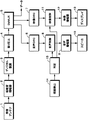
以下、この発明によるデータ再生装置の一実施形態について図1を参照して説明する。図1は、全体としてディジタル放送を受信するテレビジョン受像機を全体として示す。参照符号1は、受信アンテナを示し、受信アンテナ1の受信信号が低雑音増幅器2において、復調に必要なレベルまで増幅される。低雑音増幅器2の出力信号がディジタル復調器3に供給される。
【0010】
ディジタル復調器3は、搬送波の振幅や、位相に埋め込まれている情報を取り出す。ディジタル復調器3は、例えば搬送波再生回路、同期検波回路、シンボルタイミング回路、符号判別回路から構成されている。ディジタル復調器3の出力信号が誤り訂正回路4に供給される。送信側で誤り訂正符号が付加され、誤り訂正回路4において伝送路で生じた符号誤りが訂正される。誤り訂正回路4の出力信号がデマルチプレクサ5に供給される。
【0011】
デマルチプレクサ5は、多重化されている映像、音声およびデータをそれぞれ分離して出力する。分離された音声情報が音声デコーダ6にて復号される。分離された映像情報が映像デコーダ7にて復号される。例えば映像デコーダ7は、MPEG2(Moving Picture Experts Group Phase 2)の復号を行う。なお、ディジタル放送の場合では、送信データに対してスクランブルを施して特定の視聴者のみが受信が可能とされていることが多く、その場合には、スクランブルを解除するためのデスクランブラが設けられる。
【0012】
音声デコーダ6からのディジタル音声信号が音声制御器8および音声増幅器9を介してスピーカ10に供給される。実際には、ステレオの左右チャンネルに対応して二つの音声信号路が設けられている。映像デコーダ7からのディジタル映像信号が映像制御器11および映像増幅器12を介してディスプレイ13に供給される。必要に応じて映像信号処理回路が設けられる。ディスプレイ13は、CRT(Cathode Ray Tube)、FPD(Flat Panel Display)等である。音声制御器8および映像制御器11のそれぞれには、ディジタル信号をアナログ信号へ変換するD/A変換器が設けられている。後述するような音声および映像の再生特性の制御は、ディジタル的およびアナログ的の何れによっても可能である。
【0013】
参照符号14は、ユーザの視線がテレビジョン受像機のディスプレイ13側を向いているか否かを検出する視線検出器である。すなわち、視線検出器14は、視線の対象がディスプレイか、それ以外かを検出する。視線がディスプレイ側に向いている時には、ユーザがテレビジョン受像機による音声および映像を視聴している視聴状態、および勉強、読書等の他の作業をしながら音声および映像を視聴している「ながら」状態かの何れかと推定できる。一方、視線がディスプレイに向いていない時には、他の作業にのみ関心が向いている「集中」状態と推定できる。
【0014】
視線検出器14からの検出信号が判定部15に供給され、判定部15から音声制御器8および映像制御器11のそれぞれに対する制御信号が発生する。判定部15は、通常の視聴状態、「ながら」状態および「集中」状態の3個の状態の何れであるかを判定し、各状態に適応して音声信号および映像信号の再生特性を制御する制御信号を生成する。どのような制御を行うかは、予め設定されていると共に、ユーザが制御の内容を変更することが可能とされている。
【0015】
音声制御器8は、判定部15からの制御信号によって、例えば音量レベルを制御するものである。視聴状態における音量が最適(通常の放送受信時のレベルまたはそれ以上のレベルを意味する)とされ、「集中」状態における音量が最小(音声のオフを含む)とされ、「ながら」状態における音量が両方の間のレベルとされる。
【0016】
音声制御器8は、周波数帯域を可変したり、所定周波数帯域の強調または抑制を行うものであっても良い。例えば視聴状態における帯域幅が最も広く(通常の放送受信時の帯域幅またはそれ以上広い帯域を意味する)され、「集中」状態における帯域幅が最も狭くされ、「ながら」状態における帯域幅が両方の間の帯域幅とされる。高域側の成分をカットし、または低域側の成分をカットすることによって、帯域幅が狭くされる。さらに、低域側の成分および高域側の成分のブースト量を制御するようにしても良い。すなわち、「集中」状態が最もブースト量が少なくされる。さらに、2以上の音声制御方法を組み合わせるようにしても良い。
【0017】
映像制御器11は、判定部15からの制御信号によって、映像の再生特性例えば輝度レベルを制御するものである。視聴状態における輝度レベルが最適(通常の放送受信時の輝度レベルまたはそれ以上の輝度レベルを意味する)とされ、「集中」状態における輝度レベルが最小(映像のオフを含む)とされ、「ながら」状態における輝度レベルが両方の間のレベルとされる。映像制御器11は、解像度を制御するものであっても良い。例えば視聴状態における解像度が最適(通常の放送受信時の解像度またはそれ以上高い解像度を意味する)とされ、「集中」状態における解像度が最も低いものとされ、「ながら」状態における解像度が両方の間のものとされる。輝度レベルおよび解像度以外にコントラストを制御しても良い。さらに、集中時には、テレビジョン映像を表示しないで、代わりの映像(風景等)を表示するようにしても良い。
【0018】
視線検出器14は、一例として、テレビジョン受像機等の再生装置にCCD等の撮像素子を取り付け、撮像画像を解析することによって、ユーザがディスプレイ13を注視しているのか(視聴状態)、時々ディスプレイを見ているのか(「ながら」状態)、または全然見ていないのか(「集中」状態)を判定する構成とされている。視線検出器14では、5分、10分等の所定の時間間隔毎にユーザがディスプレイ側を見ている時間の長さが検出される。
【0019】
視線検出器14の他の構成としては、ユーザのなるべく眼の近くに装着された発光ダイオード等の発光素子と、テレビジョン受像機に設けられ、発光素子からの光を受光する受光部とからなる構成も可能である。ユーザの視線がテレビジョン受像機のディスプレイ側に向いている時にのみ、発光ダイオードからの光を受光部が受光できる。また、ユーザの頭、顔等に方向センサーを設け、正面のディスプレイ側を向いているか否かを検出し、検出した結果をテレビジョン受像機にワイヤレスで伝送しても良い。
【0020】
視線検出器14は、ユーザの視線の対象を検出する以外に視線の変化を検出する構成であっても良い。すなわち、視線の動きの程度から「ながら」状態、視聴状態および「集中」状態が判定される。例えばユーザの視線が比較的静止している場合を視聴状態であると判定し、視線が動いている場合を「ながら」状態であると判定する。「集中」状態は、視線がディスプレイに向いていないことから検出される。
【0021】
図2は、この発明の一実施形態における判定部15における処理の流れを示すフローチャートである。ステップS1において、視線検出器14による視線検出がなされる。ステップS2において、検出結果からテレビジョン受像機のディスプレイを見ている割合が検出される。一例として所定時間毎にディスプレイを見ている時間の長さの合計が算出される。
【0022】
ステップS3では、ディスプレイを見ている割合がかなり高い(例えば90%以上)か否かが判定される。90%以上であると判定されると、ステップS4において、通常のテレビジョン放送を視聴している状態に映像信号および音声信号が制御される(図2では標準再生と表記されている)。この視聴状態では、映像信号および音声信号がユーザにとって最適な再生特性で再生される。
【0023】
ステップS3で、90%以上でないと判定された場合には、次に、ステップS5において、例えば10%以上か否かが判定される。そうであると判定されると、「ながら」状態と判定され、ステップS6において、映像信号および音声信号の再生特性が「ながら」に適応したものに制御される。ステップS5において、ディスプレイを見ている割合が10%以上でないと判定されると、「集中」状態と判定され、ステップS7において、映像信号および音声信号の再生特性が「集中」状態に適応したものに制御される。
【0024】
上述したこの発明の一実施形態では、テレビジョンを視聴しながら、他の作業をしている「ながら」の状態において、他の作業に集中したい時には、再生される映像および音声の少なくとも一方が集中を妨げないような特性でもって再生される。この切り替えは、自動的になされるので、ユーザがキー等を操作する必要がない。
【0025】
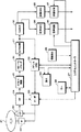
次にこの発明をディスク再生装置に対して適用した他の実施形態について、図3を参照して説明する。図3において、参照符号21が例えばマスタリング、レプリケーションの工程で作成されたディスク例えば例えばDVD(Digital Versatile Disc) を示す。参照符号22がディスク21を回転駆動するスピンドルモータであり、23がディスク21に記録された信号を再生するための光ピックアップである。
【0026】
光ピックアップ23は、レーザ光をディスク21に照射する半導体レーザ、対物レンズ等の光学系、ディスク21からの戻り光を受光するディテクタ、フォーカスおよびトラッキング機構等からなる。さらに、光ピックアップ23は、スレッド機構(図示しない)によって、ディスク21の径方向に送られる。光ピックアップ23は、光ディスク21の信号面に半導体レーザの光ビームを集光しつつ、光ディスク21上にスパイラル状に形成されたトラック上にデータを記録する。光ピックアップ23全体がスレッド機構により移動される。
【0027】
光ピックアップ23の例えば4分割ディテクタからの出力信号がRF部24に供給される。RF部24は、4分割ディテクタの各ディテクタの出力信号を演算することによって、再生(RF)信号、フォーカスエラー信号、トラッキングエラー信号を生成する。再生信号がEFMプラス復調部25に供給され、EFMプラスの復調の処理を受ける。EFMプラスにおいては、8ビットのデータシンボルを16チャンネルビットのコードワードへ変換される。この変換のためのコード変換テーブルとして、4種類のテーブルが用意されている。各テーブルは、その時の状態1〜状態4に応じて選択され、また、各テーブルでは、コードワードが選択された後の状態(次の状態)が規定されている。
【0028】
フォーカスエラー信号、トラッキングエラー信号がサーボ部26に供給される。サーボ部26は、RF信号の再生クロックに基づいてスピンドルモータ22の回転動作を制御したり、光ピックアップ23のフォーカスサーボ、トラッキングサーボを制御する。サーボ部26に対して再生装置全体の動作を制御するシステムコントローラ27からの制御信号が供給され、ディスク21上の所望の位置にアクセスすることが可能とされている。システムコントローラ27と関連してユーザが操作するキー28および表示部29が設けられている。表示部29は、液晶からなり、動作モード、再生位置等を表示する。
【0029】
EFMプラス復調部25からのディジタルデータは、RS−PC(Reed−Solomon Product Code)デコーダ30に供給され、エラー訂正の処理を受ける。RS−PCは、リード・ソロモン符号と積符号とを組み合わせた誤り訂正符号である。RS−PCデコーダ30の出力信号がセクタ分解回路31に供給される。セクタ分解回路31の出力信号がデマルチプレクサ32およびアドレスデコーダ33に供給される。
【0030】
アドレスデコーダ33によって再生アドレスが得られ、再生アドレスがサーボ部26、システムコントローラ27および表示部29に供給される。サーボ部26において再生アドレスを使用してディスク上の目標位置へのアクセスが制御される。表示部29において、再生中の位置が表示される。
【0031】
デマルチプレクサ32において、符号化音声データと符号化映像データとが分離される。符号化音声データが音声デコーダ34において復号され、音声デコーダ34からの音声データが音声制御器36に供給される。音声制御器36は、システムコントローラ27からの制御信号によって音声の再生特性を制御する。符号化映像データが映像デコーダ35において復号され、映像デコーダ35からの映像データが映像制御器37に供給される。映像制御器37は、システムコントローラ27からの制御信号によって音声の再生特性を制御する。
【0032】
音声制御器36および映像制御器37のそれぞれには、ディジタル信号をアナログ信号へ変換するD/A変換器が設けられている。ディジタル的およびアナログ的の何れかの処理によって、上述した一実施形態におけるのと同様に、音声信号および映像信号の再生特性が制御される。音声制御器36から出力された音声信号が図示しないが、音声増幅器を介してスピーカに供給され、映像制御器37から出力された映像信号が図示しないが、映像増幅器を介してディスプレイに供給される。
【0033】
上述した一実施形態におけるものと同様の視線検出器38が設けられ、視線検出器38からの検出信号がシステムコントローラ27に供給される。システムコントローラ27は、図2を参照して説明した処理と同様の処理を行い、ディスプレイを見ている割合に応じて、現在のユーザの状態が視聴状態、「ながら」状態、「集中」状態の何れであるかを判別し、判別結果に応じた制御信号を生成する。音声および映像に対する制御は、上述した一実施形態におけるものと同様になされる。
【0034】
上述したこの発明の他の実施形態においても、ディスク21に記録されている映画等のビデオソフトを鑑賞しながら他の作業を行っている「ながら」の状態において、他の作業に集中したい時には、再生される映像および音声の少なくとも一方が集中を妨げないような特性でもって再生される。この切り替えは、自動的になされるので、ユーザがキー等を操作する必要がない。
【0035】
この発明は、上述したこの発明の一実施形態等に限定されるものでは無く、この発明の要旨を逸脱しない範囲内で様々な変形や応用が可能である。例えばテレビジョン受像機およびディスク再生装置に限らず、VTR、プロジェクタ、パーソナルコンピュータ等の再生装置に対してもこの発明を適用できる。
【0036】
【発明の効果】
以上の説明から明らかなように、この発明によれば、「ながら」の状態において、他の作業に集中したい時には、再生される映像および音声の少なくとも一方が集中を妨げないような特性でもって再生されるように、自動的に切り替えることができる。また、通常の映像および音声を鑑賞している視聴状態と、「ながら」の状態との自動的な切り替えを行うことができる。
【図面の簡単な説明】
【図1】この発明の一実施形態による再生装置の構成を示すブロック図である。
【図2】この発明の一実施形態の動作を説明するためのフローチャートである。
【図3】この発明の他の実施形態による再生装置の構成を示すブロック図である。
【符号の説明】
5・・・デマルチプレクサ、6・・・音声デコーダ、7・・・映像デコーダ、8・・・音声制御器、11・・・映像制御器、14・・・視線検出器、15・・・判定部、21・・・光ディスク、25・・・EFMプラス復調部、27・・・システムコントローラ、32・・・デマルチプレクサ、34・・・音声デコーダ、35・・・映像デコーダ、36・・・音声制御器、37・・・映像制御器、38・・・視線検出器[0001]
TECHNICAL FIELD OF THE INVENTION
The present invention relates to a reproducing apparatus and a reproducing method applicable to, for example, a television receiver.
[0002]
[Prior art]
Sometimes I study or read while watching a television receiver. Such a state is a so-called "while" state.
[0003]
Japanese Patent Application Laid-Open Publication No. H11-64131 describes that the setting such as the brightness of a television receiver is set to a desired brightness level for each user using the biometric information of the user and personal authentication.
[0004]
[Patent Document 1]
Japanese Patent Application Laid-Open No. 10-212177
[Problems to be solved by the invention]
The “while” state is a state in which the user is interested in both viewing of the television receiver and other work such as studying. There is a case where the state changes from “while” to a state where the user concentrates on other work such as writing a text (denoted as “concentration” as appropriate). In this “concentration” state, the video and audio of the television receiver may be felt as disturbing the concentration.
[0006]
SUMMARY OF THE INVENTION It is therefore an object of the present invention to provide a reproducing apparatus and a reproducing method in which at least one of video and audio reproduction characteristics is changed according to a state of "while" and a state of "concentration".
[0007]
[Means for Solving the Problems]
In order to solve the above-mentioned problem, an invention according to
[0008]
According to the present invention, the degree of interest of the user in the reproduced video and audio is determined by determining the target of the user's line of sight. The degree of interest includes a first state in which the user views the reproduced video and audio (normal viewing state), and a second state in which the user views the reproduced video and audio while performing other operations. A state ("while" state) and a third state ("concentration" state) that concentrates on other work are included. Based on the determination result, the reproduction characteristics of at least one of video and audio are controlled in accordance with each state.
[0009]
BEST MODE FOR CARRYING OUT THE INVENTION
Hereinafter, an embodiment of a data reproducing apparatus according to the present invention will be described with reference to FIG. FIG. 1 shows a television receiver as a whole for receiving digital broadcasting.
[0010]
The
[0011]
The demultiplexer 5 separates and outputs multiplexed video, audio, and data. The separated audio information is decoded by the audio decoder 6. The separated video information is decoded by the video decoder 7. For example, the video decoder 7 decodes MPEG2 (Moving Picture Experts Group Phase 2). In the case of digital broadcasting, transmission data is often scrambled so that only a specific viewer can receive the data. In this case, a descrambler for descrambling is provided. .
[0012]
A digital audio signal from the audio decoder 6 is supplied to a
[0013]
Reference numeral 14 is a line-of-sight detector that detects whether or not the user's line of sight is facing the
[0014]
The detection signal from the line-of-sight detector 14 is supplied to the
[0015]
The audio controller 8 controls, for example, a volume level according to a control signal from the
[0016]
The audio controller 8 may change the frequency band, or may emphasize or suppress a predetermined frequency band. For example, the bandwidth in the viewing state is the widest (meaning the bandwidth at the time of normal broadcast reception or wider), the bandwidth in the “concentrated” state is the narrowest, and the bandwidth in the “while” state is both Between the bandwidth. By cutting high-frequency components or low-frequency components, the bandwidth is narrowed. Further, the boost amounts of the low-frequency component and the high-frequency component may be controlled. That is, the boost amount is minimized in the “concentration” state. Further, two or more voice control methods may be combined.
[0017]
The
[0018]
As an example, the eye gaze detector 14 attaches an image sensor such as a CCD to a playback device such as a television receiver, and analyzes the captured image to determine whether the user is watching the display 13 (viewing state). It is configured to determine whether the user is looking at the display ("while" state) or not at all ("concentration" state). The line-of-sight detector 14 detects the length of time the user is looking at the display at predetermined time intervals such as 5 minutes, 10 minutes, or the like.
[0019]
Another configuration of the line-of-sight detector 14 includes a light-emitting element such as a light-emitting diode mounted as close as possible to the user's eyes, and a light-receiving unit provided in the television receiver and receiving light from the light-emitting element. A configuration is also possible. The light receiving unit can receive light from the light emitting diode only when the user's line of sight is facing the display side of the television receiver. Alternatively, a direction sensor may be provided on the user's head, face, or the like to detect whether or not the user is facing the front display side, and the detection result may be wirelessly transmitted to the television receiver.
[0020]
The line of sight detector 14 may be configured to detect a change in the line of sight in addition to detecting the target of the line of sight of the user. That is, the “while” state, the viewing state, and the “concentration” state are determined based on the degree of the line of sight movement. For example, a case where the user's line of sight is relatively stationary is determined to be the viewing state, and a case where the user's line of sight is moving is determined to be the “while” state. The “concentration” state is detected because the line of sight is not facing the display.
[0021]
FIG. 2 is a flowchart showing a flow of processing in the
[0022]
In step S3, it is determined whether the ratio of viewing the display is considerably high (for example, 90% or more). If it is determined that it is 90% or more, in step S4, the video signal and the audio signal are controlled in a state where a normal television broadcast is being watched (in FIG. 2, it is described as standard reproduction). In this viewing state, the video signal and the audio signal are reproduced with reproduction characteristics optimal for the user.
[0023]
If it is determined in step S3 that it is not 90% or more, then it is determined in step S5 whether it is, for example, 10% or more. If so, it is determined that the state is "while", and in step S6, the reproduction characteristics of the video signal and the audio signal are controlled to those adapted to "while". If it is determined in step S5 that the ratio of watching the display is not 10% or more, it is determined that the state is "concentration", and in step S7, the reproduction characteristics of the video signal and the audio signal are adapted to the "concentration" state. Is controlled.
[0024]
In the embodiment of the present invention described above, in a state of “while” while performing other work while watching television, when it is desired to concentrate on other work, at least one of the reproduced video and audio is concentrated. Is reproduced with characteristics that do not hinder the reproduction. Since this switching is performed automatically, there is no need for the user to operate keys and the like.
[0025]
Next, another embodiment in which the present invention is applied to a disk reproducing apparatus will be described with reference to FIG. In FIG. 3,
[0026]
The
[0027]
An output signal from, for example, a quadrant detector of the
[0028]
The focus error signal and the tracking error signal are supplied to the
[0029]
The digital data from the EFM plus
[0030]
A reproduction address is obtained by the
[0031]
In the
[0032]
Each of the
[0033]
A line-of-
[0034]
In the above-described other embodiment of the present invention, when the user wants to concentrate on other work while performing other work while watching video software such as a movie recorded on the
[0035]
The present invention is not limited to the above-described embodiment of the present invention, and various modifications and applications are possible without departing from the gist of the present invention. For example, the present invention can be applied not only to a television receiver and a disc reproducing device but also to a reproducing device such as a VTR, a projector, and a personal computer.
[0036]
【The invention's effect】
As is apparent from the above description, according to the present invention, when the user wants to concentrate on other work in the "while" state, at least one of the reproduced video and audio is reproduced with a characteristic that does not hinder the concentration. Can be switched automatically as they are. In addition, it is possible to automatically switch between a viewing state in which normal video and audio are being watched and a “while” state.
[Brief description of the drawings]
FIG. 1 is a block diagram showing a configuration of a playback device according to an embodiment of the present invention.
FIG. 2 is a flowchart for explaining the operation of one embodiment of the present invention.
FIG. 3 is a block diagram showing a configuration of a reproducing apparatus according to another embodiment of the present invention.
[Explanation of symbols]
5 Demultiplexer, 6 Audio decoder, 7 Video decoder, 8 Audio controller, 11 Video controller, 14 Eye gaze detector, 15 Judgment Unit, 21 optical disk, 25 EFM plus demodulator, 27 system controller, 32 demultiplexer, 34 audio decoder, 35 video decoder, 36 audio Controller, 37 ... Video controller, 38 ... Eye gaze detector
Claims (12)
ユーザの視線を検出する視線検出手段と、
上記視線検出手段によって得られた検出情報から再生される映像および音声に対するユーザの関心の程度を判定する判定手段と、
上記判定手段から得られた判定結果によって上記映像および音声の少なくとも一方の再生特性を変化させる制御手段とを有する再生装置。A playback device that plays back video and audio,
Gaze detection means for detecting the gaze of the user;
Determining means for determining the degree of interest of the user in video and audio reproduced from the detection information obtained by the eye-gaze detecting means;
A control unit configured to change a reproduction characteristic of at least one of the video and the audio based on a determination result obtained from the determination unit.
上記視線検出手段は、視線の対象を検出する手段である再生装置。In claim 1,
A reproduction apparatus, wherein the line-of-sight detection means is means for detecting a line-of-sight target.
上記視線検出手段は、視線の変化を検出する手段である再生装置。In claim 1,
A reproduction apparatus, wherein the line-of-sight detecting means is a means for detecting a change in the line of sight.
上記判定手段は、再生される映像および音声をユーザが視聴する第1の状態と、他の作業を行いながら、上記再生される映像および音声をユーザが視聴する第2の状態と、上記他の作業に集中する第3の状態との少なくとも2つを判別する再生装置。In claim 1,
The determination means includes: a first state in which the user views the reproduced video and audio; a second state in which the user views the reproduced video and audio while performing other operations; A playback device that determines at least two of a third state in which the user concentrates on work;
上記制御手段は、音声の再生特性を制御するデータ再生装置。In claim 1,
The control means is a data reproducing device for controlling a reproduction characteristic of audio.
上記制御手段は、映像の再生特性を制御するデータ再生装置。In claim 1,
The above-mentioned control means is a data reproducing device for controlling a reproduction characteristic of a video.
ユーザの視線を検出する視線検出ステップと、
上記視線検出ステップによって得られた検出情報から再生される映像および音声に対するユーザの関心の程度を判定する判定ステップと、
上記判定ステップから得られた判定結果によって上記映像および音声の少なくとも一方の再生特性を変化させる制御ステップとを有する再生方法。A playback method for playing back video and audio,
A gaze detection step of detecting a gaze of the user;
A determining step of determining a degree of interest of the user in video and audio reproduced from the detection information obtained by the eye-gaze detecting step;
A control step of changing at least one of the video and audio reproduction characteristics according to a result of the determination obtained from the determination step.
上記視線検出ステップは、視線の対象を検出するステップである再生方法。In claim 7,
The eye gaze detecting step is a step of detecting an eye gaze target.
上記視線検出ステップは、視線の変化を検出するステップである再生方法。In claim 7,
The reproduction method, wherein the gaze detection step is a step of detecting a change in gaze.
上記判定ステップは、再生される映像および音声をユーザが視聴する第1の状態と、他の作業を行いながら、上記再生される映像および音声をユーザが視聴する第2の状態と、上記他の作業に集中する第3の状態との少なくとも2つを判別する再生方法。In claim 7,
The determination step includes a first state in which the user views the reproduced video and audio, a second state in which the user views the reproduced video and audio while performing other operations, and the other state. A reproduction method for discriminating at least two of a third state in which the user concentrates on work.
上記制御ステップは、音声の再生特性を制御するデータ再生方法。In claim 7,
The control step is a data reproduction method for controlling a reproduction characteristic of audio.
上記制御ステップは、映像の再生特性を制御するデータ再生方法。In claim 7,
The control step is a data reproduction method for controlling reproduction characteristics of an image.
Priority Applications (7)
| Application Number | Priority Date | Filing Date | Title |
|---|---|---|---|
| JP2003103532A JP2004312401A (en) | 2003-04-08 | 2003-04-08 | Apparatus and method for reproducing |
| PCT/JP2004/004716 WO2004091199A1 (en) | 2003-04-08 | 2004-03-31 | Reproduction device and reproduction method |
| CA002487396A CA2487396A1 (en) | 2003-04-08 | 2004-03-31 | Reproduction device and reproduction method |
| EP04724870.3A EP1613069B1 (en) | 2003-04-08 | 2004-03-31 | Reproduction device and reproduction method |
| KR1020047019937A KR20060002710A (en) | 2003-04-08 | 2004-03-31 | Reproduction device and reproduction method |
| US10/512,084 US7415191B2 (en) | 2003-04-08 | 2004-03-31 | Reproduction device and reproduction method |
| CN200480000324XA CN1698354B (en) | 2003-04-08 | 2004-03-31 | Reproduction device and reproduction method |
Applications Claiming Priority (1)
| Application Number | Priority Date | Filing Date | Title |
|---|---|---|---|
| JP2003103532A JP2004312401A (en) | 2003-04-08 | 2003-04-08 | Apparatus and method for reproducing |
Publications (2)
| Publication Number | Publication Date |
|---|---|
| JP2004312401A true JP2004312401A (en) | 2004-11-04 |
| JP2004312401A5 JP2004312401A5 (en) | 2005-06-16 |
Family
ID=33156828
Family Applications (1)
| Application Number | Title | Priority Date | Filing Date |
|---|---|---|---|
| JP2003103532A Pending JP2004312401A (en) | 2003-04-08 | 2003-04-08 | Apparatus and method for reproducing |
Country Status (7)
| Country | Link |
|---|---|
| US (1) | US7415191B2 (en) |
| EP (1) | EP1613069B1 (en) |
| JP (1) | JP2004312401A (en) |
| KR (1) | KR20060002710A (en) |
| CN (1) | CN1698354B (en) |
| CA (1) | CA2487396A1 (en) |
| WO (1) | WO2004091199A1 (en) |
Cited By (6)
| Publication number | Priority date | Publication date | Assignee | Title |
|---|---|---|---|---|
| US20090097822A1 (en) * | 2006-05-15 | 2009-04-16 | Kyoji Hirata | Method for optimizing the reading by a user equipment of mcch (mbms point-to-multipoint control channel) information |
| JP2010154395A (en) * | 2008-12-26 | 2010-07-08 | Sony Corp | Information processing apparatus and method, and program |
| JP2011166572A (en) * | 2010-02-12 | 2011-08-25 | Nec Personal Products Co Ltd | Apparatus for estimation of program preference, image viewing system, program viewing confirmation method, and program |
| JP2016502201A (en) * | 2012-11-29 | 2016-01-21 | マイクロソフト テクノロジー ライセンシング,エルエルシー | Resource management for head mounted display |
| US9967690B2 (en) | 2010-11-05 | 2018-05-08 | Sony Corporation | Acoustic control apparatus and acoustic control method |
| JP2018107576A (en) * | 2016-12-26 | 2018-07-05 | ヤマハ株式会社 | Reproduction control method and system |
Families Citing this family (11)
| Publication number | Priority date | Publication date | Assignee | Title |
|---|---|---|---|---|
| JP2008258749A (en) * | 2007-04-02 | 2008-10-23 | Funai Electric Co Ltd | Thin television set and audio apparatus |
| RU2501095C2 (en) * | 2007-11-20 | 2013-12-10 | Конинклейке Филипс Электроникс Н.В. | Power-saving transmissive display |
| JP5299866B2 (en) * | 2009-05-19 | 2013-09-25 | 日立コンシューマエレクトロニクス株式会社 | Video display device |
| US8255820B2 (en) | 2009-06-09 | 2012-08-28 | Skiff, Llc | Electronic paper display device event tracking |
| JP5263092B2 (en) | 2009-09-07 | 2013-08-14 | ソニー株式会社 | Display device and control method |
| EP2333778A1 (en) * | 2009-12-04 | 2011-06-15 | Lg Electronics Inc. | Digital data reproducing apparatus and method for controlling the same |
| CN102054510A (en) * | 2010-11-08 | 2011-05-11 | 武汉大学 | Video preprocessing and playing method and system |
| JP5772069B2 (en) * | 2011-03-04 | 2015-09-02 | ソニー株式会社 | Information processing apparatus, information processing method, and program |
| CN104052949B (en) * | 2013-03-14 | 2019-03-29 | 联想(北京)有限公司 | Volume adjusting method, device and electronic equipment |
| KR102098277B1 (en) | 2013-06-11 | 2020-04-07 | 삼성전자주식회사 | Visibility improvement method based on eye tracking, machine-readable storage medium and electronic device |
| EP3037915B1 (en) * | 2014-12-23 | 2017-08-16 | Nokia Technologies OY | Virtual reality content control |
Family Cites Families (17)
| Publication number | Priority date | Publication date | Assignee | Title |
|---|---|---|---|---|
| US4513317A (en) * | 1982-09-28 | 1985-04-23 | The United States Of America As Represented By The Administrator Of The National Aeronautics And Space Administration | Retinally stabilized differential resolution television display |
| US4836670A (en) * | 1987-08-19 | 1989-06-06 | Center For Innovative Technology | Eye movement detector |
| US4931865A (en) * | 1988-08-24 | 1990-06-05 | Sebastiano Scarampi | Apparatus and methods for monitoring television viewers |
| JPH0818950A (en) * | 1994-06-29 | 1996-01-19 | Sharp Corp | Video intercom |
| US6078349A (en) * | 1995-06-07 | 2000-06-20 | Compaq Computer Corporation | Process and system for increasing the display resolution of a point-to-point video transmission relative to the actual amount of video data sent |
| JPH099229A (en) | 1995-06-15 | 1997-01-10 | Oki Electric Ind Co Ltd | Multi-spot conference system |
| JPH09275533A (en) * | 1996-04-08 | 1997-10-21 | Sony Corp | Signal processor |
| US6353764B1 (en) * | 1997-11-27 | 2002-03-05 | Matsushita Electric Industrial Co., Ltd. | Control method |
| JPH11288259A (en) * | 1998-02-06 | 1999-10-19 | Sanyo Electric Co Ltd | Method and device for power saving control |
| JP3488092B2 (en) * | 1998-08-06 | 2004-01-19 | 松下電器産業株式会社 | Broadcast receiving apparatus and receiving program selection method |
| JP2001100870A (en) | 1999-09-28 | 2001-04-13 | Toshiba Corp | Information processor |
| JP2001128134A (en) * | 1999-11-01 | 2001-05-11 | Atr Media Integration & Communications Res Lab | Presentation device |
| WO2001084838A1 (en) | 2000-04-28 | 2001-11-08 | Swisscom Mobile Ag | Method and system for video conferences |
| JP3644502B2 (en) * | 2001-02-06 | 2005-04-27 | ソニー株式会社 | Content receiving apparatus and content presentation control method |
| US7171108B1 (en) * | 2001-07-31 | 2007-01-30 | Keen Personal Media, Inc. | Audiovisual system to interrupt viewing of a first audiovisual program to provide notification of a second audiovisual program of interest to the user |
| US7284201B2 (en) * | 2001-09-20 | 2007-10-16 | Koninklijke Philips Electronics N.V. | User attention-based adaptation of quality level to improve the management of real-time multi-media content delivery and distribution |
| US7003139B2 (en) * | 2002-02-19 | 2006-02-21 | Eastman Kodak Company | Method for using facial expression to determine affective information in an imaging system |
-
2003
- 2003-04-08 JP JP2003103532A patent/JP2004312401A/en active Pending
-
2004
- 2004-03-31 US US10/512,084 patent/US7415191B2/en active Active
- 2004-03-31 CN CN200480000324XA patent/CN1698354B/en not_active Expired - Fee Related
- 2004-03-31 EP EP04724870.3A patent/EP1613069B1/en not_active Expired - Fee Related
- 2004-03-31 WO PCT/JP2004/004716 patent/WO2004091199A1/en active Application Filing
- 2004-03-31 CA CA002487396A patent/CA2487396A1/en not_active Abandoned
- 2004-03-31 KR KR1020047019937A patent/KR20060002710A/en not_active Application Discontinuation
Cited By (9)
| Publication number | Priority date | Publication date | Assignee | Title |
|---|---|---|---|---|
| US20090097822A1 (en) * | 2006-05-15 | 2009-04-16 | Kyoji Hirata | Method for optimizing the reading by a user equipment of mcch (mbms point-to-multipoint control channel) information |
| US8290341B2 (en) * | 2006-05-15 | 2012-10-16 | Nec Corporation | Video playing device, video playing method, and video playing program having automatic video selections based upon user concentration |
| JP2010154395A (en) * | 2008-12-26 | 2010-07-08 | Sony Corp | Information processing apparatus and method, and program |
| US9179191B2 (en) | 2008-12-26 | 2015-11-03 | Sony Corporation | Information processing apparatus, information processing method, and program |
| JP2011166572A (en) * | 2010-02-12 | 2011-08-25 | Nec Personal Products Co Ltd | Apparatus for estimation of program preference, image viewing system, program viewing confirmation method, and program |
| US9967690B2 (en) | 2010-11-05 | 2018-05-08 | Sony Corporation | Acoustic control apparatus and acoustic control method |
| JP2016502201A (en) * | 2012-11-29 | 2016-01-21 | マイクロソフト テクノロジー ライセンシング,エルエルシー | Resource management for head mounted display |
| US9851787B2 (en) | 2012-11-29 | 2017-12-26 | Microsoft Technology Licensing, Llc | Display resource management |
| JP2018107576A (en) * | 2016-12-26 | 2018-07-05 | ヤマハ株式会社 | Reproduction control method and system |
Also Published As
| Publication number | Publication date |
|---|---|
| US20050207725A1 (en) | 2005-09-22 |
| EP1613069A1 (en) | 2006-01-04 |
| CA2487396A1 (en) | 2004-10-21 |
| US7415191B2 (en) | 2008-08-19 |
| EP1613069A4 (en) | 2006-04-12 |
| CN1698354B (en) | 2010-06-16 |
| WO2004091199A1 (en) | 2004-10-21 |
| KR20060002710A (en) | 2006-01-09 |
| EP1613069B1 (en) | 2020-02-26 |
| CN1698354A (en) | 2005-11-16 |
Similar Documents
| Publication | Publication Date | Title |
|---|---|---|
| JP2004312401A (en) | Apparatus and method for reproducing | |
| US20070031119A1 (en) | Playback apparatus | |
| US6119259A (en) | Method and apparatus of improving reliability of a descrambling operation in a DVD player | |
| JP4103146B2 (en) | Digital broadcast receiver | |
| JPWO2007094143A1 (en) | Information processing apparatus, method thereof, program thereof, recording medium recording the program, DJ playback apparatus, and playback apparatus | |
| JP4031918B2 (en) | Playback device | |
| KR20060007639A (en) | Data reproducing device for controlling display state of subtitle and method thereof | |
| JP2006261892A (en) | Television receiving set and its program reproducing method | |
| JP2003046951A5 (en) | ||
| JP4187001B2 (en) | Optical disc recording / reproducing apparatus | |
| JP3668212B2 (en) | Digital information receiving apparatus and digital information receiving method | |
| US20060083140A1 (en) | Disk apparatus and adjusting method thereof | |
| US20080005762A1 (en) | Data broadcast playback apparatus and method of the same | |
| JP4480971B2 (en) | Optical disk playback device | |
| JP2007213661A (en) | Audio reproducing device | |
| JP2612693B2 (en) | Video signal processing device for disk playback device | |
| JP3734084B2 (en) | Optical disk playback device | |
| KR20070121358A (en) | Dynamic video output method of combo device and its system | |
| KR100501931B1 (en) | Method for adjusting the optimized aspect ratio according to dvd input source and dvd-player using the same | |
| KR100584172B1 (en) | Apparatus and method for converting subtitle data of optical disc to voice | |
| JP2003143526A (en) | Dvd player | |
| JP2007213662A (en) | Sound reproducing device | |
| JP2010166352A (en) | Copying device | |
| JP2007234089A (en) | Recording and reproducing device | |
| JP2010124417A (en) | Information reproduction device and information reproduction method |
Legal Events
| Date | Code | Title | Description |
|---|---|---|---|
| A521 | Written amendment |
Free format text: JAPANESE INTERMEDIATE CODE: A523 Effective date: 20040921 |
|
| A621 | Written request for application examination |
Free format text: JAPANESE INTERMEDIATE CODE: A621 Effective date: 20040921 |
|
| A131 | Notification of reasons for refusal |
Free format text: JAPANESE INTERMEDIATE CODE: A131 Effective date: 20060221 |
|
| A02 | Decision of refusal |
Free format text: JAPANESE INTERMEDIATE CODE: A02 Effective date: 20060620 |