JP2004307252A - Quartz glass sealed body - Google Patents
Quartz glass sealed body Download PDFInfo
- Publication number
- JP2004307252A JP2004307252A JP2003102537A JP2003102537A JP2004307252A JP 2004307252 A JP2004307252 A JP 2004307252A JP 2003102537 A JP2003102537 A JP 2003102537A JP 2003102537 A JP2003102537 A JP 2003102537A JP 2004307252 A JP2004307252 A JP 2004307252A
- Authority
- JP
- Japan
- Prior art keywords
- glass
- quartz glass
- sealing
- quartz
- sealed body
- Prior art date
- Legal status (The legal status is an assumption and is not a legal conclusion. Google has not performed a legal analysis and makes no representation as to the accuracy of the status listed.)
- Pending
Links
Images


Classifications
-
- C—CHEMISTRY; METALLURGY
- C03—GLASS; MINERAL OR SLAG WOOL
- C03C—CHEMICAL COMPOSITION OF GLASSES, GLAZES OR VITREOUS ENAMELS; SURFACE TREATMENT OF GLASS; SURFACE TREATMENT OF FIBRES OR FILAMENTS MADE FROM GLASS, MINERALS OR SLAGS; JOINING GLASS TO GLASS OR OTHER MATERIALS
- C03C27/00—Joining pieces of glass to pieces of other inorganic material; Joining glass to glass other than by fusing
- C03C27/04—Joining glass to metal by means of an interlayer
- C03C27/042—Joining glass to metal by means of an interlayer consisting of a combination of materials selected from glass, glass-ceramic or ceramic material with metals, metal oxides or metal salts
- C03C27/044—Joining glass to metal by means of an interlayer consisting of a combination of materials selected from glass, glass-ceramic or ceramic material with metals, metal oxides or metal salts of glass, glass-ceramic or ceramic material only
Abstract
Description
【0001】
【発明の属する技術分野】
本発明は石英ガラス封着体、さらに詳細には高気密性を必要とする高真空機器類のビューポートや、耐紫外線に優れたセンサー類のレンズ及び光通信部品用に関する石英ガラス封着体に関する。
【0002】
【従来の技術】
従来の金属に石英ガラスを封着するには、各用途によって封着方法が異なり、例えば放電管のような場合には中間ガラスなどを用いずに直接金属(モリブデンやタングステンなどの高融点金属線や箔)にバーナーで約1800℃融着させる方法がある(特開2002−190275号)。
【0003】
また中間ガラスを用いる場合は、金属との膨張差が桁違いに異なるためグレイティッドシールが採用されている。すなわち石英ガラス側はホウ珪酸系の石英ガラスに近い低膨張タイプにし、漸次金属側に向かって高膨張にし、封着すべき外周金属接合界面では金属にあわせる方式の複合傾斜機能積層ガラスが考えられている。またレンズ関連では、中間ガラスとして鉛系の低融点ガラスを用いるものや接合する箇所にメタライズを施してはんだシールする方式などがある(特開2001−240428号)。
【0004】
石英ガラスを用いた石英ガラス封着体は光学特性、耐環境性能、耐熱高強度特性など他に類をみない秀でた性能を有するため、多様な分野で用いられている。
【0005】
【特許文献1】
特開2002−190275号
【特許文献2】
特開2001−240428号
【0006】
【発明が解決しようとする課題】
前述の従来法である直接石英を金属に融着させる方法では、接合金属が高融点かつ低膨張であるモリブデンやタングステン及びそれらの合金に限定され、融点が1400〜1500℃前後の一般的なステンレスやFe及びFe/Ni合金などの金属の封着には用いることは出来ない。
【0007】
更に石英ガラスの組み立て加工精度、特に表面の平坦性が要求される場合にはバーナーワークでは前記平坦性を保持することは出来ない問題がある。このようなことから石英を直接融着する技術は放電管のような高融点の導入線や箔などにメカ的な加圧を併用しながら成形する管状タイプが主であり応用範囲が限定され自由度が少ない問題を有している。
【0008】
また金属と石英ガラスを接合するのに旧来からのグレティッドシール法の複合傾斜機能積層ガラスがある。これは大きな差を有する金属と石英を中間ガラスなるもので接合するときに、膨張差によるガラス内に生ずる内部応力を最小限にするための手法で、高品質な製品が可能であるが、作業的には各種積層していくガラスの作業温度の違いにより工程がかかり工数アップとともに高価になる問題を有している。
【0009】
従来の高温/高真空装置などののぞき窓やセンサー類のレンズのような外周金属を有した内側に石英をガラスで接合する場合は、低融点ガラスが使用されている。これは低温域で作業でするため熱膨張係数差の軽減につながる効果があり実用化されている。しかしながら鉛が添加されているため環境問題から、鉛レスの低融点ガラスが開発されだしてきているが、いずれにしても高気密/高強度/高耐熱を要求されるような高信頼性製品にはなし得ないのが現状である。
【0010】
本発明は上述の課題を解決するためなされたものであり、融点が1400〜1500℃のステンレスあるいは鉄、Fe/Ni/Co合金、Fe/Ni合金などに容易に石英ガラスを封着可能で、基本的に鉛を含まない封着ガラス層を備えた石英ガラス封着体を提供することを目的とする。
【0011】
【課題を解決するための手段】
上記課題を解決するために、中空円筒状の外周金属の内壁に封着ガラスを介して石英ガラスを気密に封着した三重円筒構造の石英ガラス封着体において、前記封着ガラスは前記石英ガラスと外周金属の中間に位置する熱膨張係数を有するホウ珪酸系ガラスであることを特徴を有する。
【0012】
さらに、本発明による石英ガラス封着体は、前記封着体において、石英ガラスの外径をa、ホウ珪酸系ガラスの外径をb、そして外周金属の外径をcとしたとき、
b≧1.10a及びc≧1.04b
であることを特徴を有する。
【0013】
また前記封着体の外周金属はFe−Ni−Co合金、、Fe/Ni合金、ステンレス、鉄を採用し、封着ガラスの熱膨張係数は20〜40×10−7/Kであることを特徴を有する。
【0014】
本発明の石英ガラスの封着は単層の封着ガラスを用いて封着されるので、石英ガラスを直接融着する温度域まで上げる必要が無く金属の選定において白由度が広まり、ステンレス、Fe、Fe/Ni合金、Fe/Ni/Co合金などの材料が使用できかつ一回の封着作業で完成し、石英ガラスの軟化しない作業温度であるので表面の平坦度を維持し、組み立て精度の向上になる。
【0015】
更に封着ガラスとしてホウ珪酸系の無鉛硬質ガラスの採用によって環境に影響を与えずかつ高耐熱・高強度・高気密を有した高信頼性製品に対応してる。
【0016】
本発明の石英ガラスの封着は、三重円筒構造を基本にしており従来の内部応力の影響を逆に利用してガラスに圧縮応力を残留させたコンプレッションシールタイプである。
【0017】
【発明の実施の態様】
以下に発明の実施の態様を図および表を参照しながら説明する。
【0018】
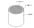
図1及び図2は、本発明による石英ガラス封着体の一実施態様の斜視図及び断面図であるが、この図より明らかなように、中空円筒状の外周金属1の内壁に封着ガラス2を介して、石英ガラス3を封着した構造になっている。
【0019】
図3は、本発明による石英ガラス封着体の他の態様の断面図であるが、この図の石英ガラス封着体は中空円筒本体11の端部12が直角に折曲された構造の外周金属1を備えている。そして前記端部12の端面13に封着ガラス2を介して石英ガラス3を封着した構造になっている。
【0020】
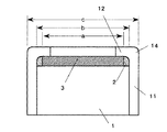
図4は本発明による他の態様であって、図3に示すのと同様に中空円筒の端部が折曲された構造の外周金属1に石英ガラス3を封着したもので、円筒本体11の折曲部14の円筒本体11と端部12の内壁にかけて封着ガラス2を設け、この封着ガラス2を介して石英ガラス3を封着した構造になっている。
【0021】
図5は本発明による他の態様であって、図4に示すのと同様中空円筒の端部が折曲された構造の外周金属1に石英ガラス3を封着したもので、前記折曲部14の内壁に封着ガラス2を設け、この封着ガラス2を介して石英ガラスを封着した構造を示している。
【0022】
前記図1〜5の石英ガラス封着体において、石英ガラスの外径をa、ホウ珪酸系ガラスの外径をb、そして外周金属の外径をcとしたとき、
b≧1.10a及びc≧1.04b
である。後述の実施例よりも明らかなように、有限要素法によるシミュレーション解析と力学的計算式に基づいた応力計算結果とそして実験結果によって、本発明者は、本関係式を導いた。この関係式から逸脱した石英ガラス封着体は、封着ガラスに引っ張り的な内部応力がかかりクラックやリークの発生する現象が現れる。
【0023】
前記外周金属としては、融点が1400〜1500℃の汎用的な金属であるのがコスト面より好ましく、ステンレスあるいは鉄、Fe/Ni/Co合金、Fe/Ni合金などを有効に使用することができる。このような金属の熱膨張係数は40〜185×10−7/Kであるのがよい。上記の範囲を逸脱すると、ホウ珪酸系ガラスの熱膨張係数との差が大きくなりクラックなどを生じやすくなる。
【0024】
ホウ珪酸系ガラスの熱膨張係数は、好ましくは20〜40×10−7/Kである。上述の熱膨張率係数を逸脱すると、石英ガラスの膨張係数約5.5×10−7/Kおよび前記外周金属の熱膨張係数との差が大きくなりクラックなどを生じやすくなるからである。
【0025】
【実施例】
図1は、本発明に関わる石英ガラス封着体の基本的な実験構造を示し、表1及び2には、図1中のa,b及びc寸法を各種組み合わせした内容を示している。表1は外周金属の外径/内径が8.3φ/7.7φという同サイズのものを用いて石英ガラスのサイズを変化させたb/a比率変化である。
【0026】
また表2は石英ガラス外径サイズを固定し、外周金属の外径/内径であるc/b比を変化させている。
【0027】
使用する材料は、外周金属としてコバール(Fe/Ni/Co合金)とSUS304(ステンレス)の二種、封着ガラスはコーニング社のホウ珪酸系ガラスコード7070を用いた。外周金属のコバールおよびSUS304の熱膨張係数は、それぞれ50×10−7/K、184×10−7/Kであり、コーニング7070(ホウ珪酸ガラス)の熱膨張係数は32×10−7/Kであった。
【0028】
表1の14種類並びに表2の10種類を作製し評価した。評価方法としては、ガラス焼成後のガラスクラック検査、ヘリウムリーク試験、更に熱衝撃試験、半田耐熱試験の負荷試験後のガラスクラック検査及びヘリウムリーク試験を評価した。判定基準は、ガラスクラックは30倍の拡大鏡で目視検査し、確認されないものを合格とした。またヘリウムリーク試験はガラス封止部の気密度をヘリウムリークディテクターにて測定し、1×10⁻¹⁰Pa・m3/s以下を合格として判定した。
【0029】
熱衝撃の試験条件は、気相中にて−65℃(30分)→常温(15秒)→+300℃(30分)を1サイクルとして5サイクル実施。また半田耐熱試験は、350℃の溶融半田に10秒間浸漬する。
【0030】
石英サイズ変化試作評価結果を表3に外周金属変化試作評価結果を表4に示した。表3から明らかなように試料1−1〜1−5と1−8〜1−12まではガラス焼成後と熱衝撃、半田耐熱の負荷試験後においてもクラックリークが発生しないことが確認された。これは外周金属の内径と石英ガラスの外径の比(b/a)が1.10以上は合格となり、それ以下では不合格になることを示している。かようなことより石英封着体の三重円筒構造体においてb≧1.10aにする必要がある。
【0031】
表4から明らかなように試料2−1〜2−3、2−6〜2−8において合格であることが確認された。これは外周金属の厚み、すなわち外径と内径の比率変化で1.04以上というc≧1.04bの関係を意味している。表3並びに表4の結果において寸法変化とともに外周金属の材質についても調査しているが両者ともに同様の関係式が成り立った。
【0032】
【表1】

【表2】
【表3】
【表4】
【発明の効果】
以上説明したように本発明による石英ガラス封着体によれば、単層の封着ガラスを用いて封着されるので、石英ガラスを直接融着する温度域まで上げる必要が無く、外周金属の選定において白由度が広まり、Fe/Ni/Co合金、ステンレス、FeまたはFe/Ni合金などの材料が使用できかつ一回の封着作業で完成し、石英ガラスの軟化しない作業温度であるので表面の平坦度を維持し、組み立て精度の向上になる。更に封着ガラスとしてホウ珪酸系の無鉛硬質ガラスの採用によって環境に影響を与えずかつ高耐熱・高強度・高気密を有した高信頼性製品を製造可能である。
【図面の簡単な説明】
【図1】本発明の一実施態様の石英ガラス封着体の基本的な構造を示す斜視図。
【図2】前記実施例の断面図。
【図3】本発明の他の実施態様の断面図
【図4】本発明の他の実施態様の断面図
【図5】本発明の他の実施態様の断面図
【符号の説明】
1 外周金属
2 封着ガラス
3 石英ガラス[0001]
TECHNICAL FIELD OF THE INVENTION
The present invention relates to a quartz glass sealed body, and more particularly, to a quartz glass sealed body for use in a viewport of high vacuum equipment requiring high airtightness, a lens of a sensor excellent in ultraviolet light resistance, and an optical communication component. .
[0002]
[Prior art]
In order to seal quartz glass to a conventional metal, the sealing method differs depending on each application. For example, in the case of a discharge tube, a metal (a high melting point metal wire such as molybdenum or tungsten) is directly used without using an intermediate glass. (Japanese Patent Laid-Open No. 2002-190275).
[0003]
In the case of using an intermediate glass, a graded seal is employed because the difference in expansion from the metal differs by orders of magnitude. In other words, it is conceivable to use a composite gradient functional laminated glass in which the quartz glass side is of a low expansion type close to borosilicate-based quartz glass, is gradually expanded toward the metal side, and is adjusted to the metal at the outer metal joint interface to be sealed. ing. As for lenses, there are a method using a lead-based low-melting glass as an intermediate glass and a method of performing metallization on a joint portion and sealing with solder (Japanese Patent Laid-Open No. 2001-240428).
[0004]
BACKGROUND ART A quartz glass sealed body using quartz glass is used in various fields because it has unparalleled excellent performance such as optical characteristics, environmental resistance performance, heat resistance and high strength characteristics.
[0005]
[Patent Document 1]
JP 2002-190275 A [Patent Document 2]
JP 2001-240428 A
[Problems to be solved by the invention]
In the above-described conventional method of fusing direct quartz to a metal, the joining metal is limited to molybdenum, tungsten, and alloys thereof having a high melting point and low expansion, and a general stainless steel having a melting point of about 1400 to 1500 ° C. It cannot be used for sealing metals such as Fe and Fe / Fe / Ni alloys.
[0007]
Further, when the accuracy of assembling quartz glass, particularly the flatness of the surface is required, there is a problem that the flatness cannot be maintained by a burner work. For this reason, the technology for directly fusing quartz is mainly of the tubular type, which is formed by applying mechanical pressure to a high melting point lead wire or foil, such as a discharge tube, and its application range is limited and free. It has a minor problem.
[0008]
In addition, there is a composite laminated functionally graded glass of a traditional graded sealing method for joining metal and quartz glass. This is a method to minimize the internal stress generated in the glass due to the difference in expansion when joining a metal having a large difference and quartz with an intermediate glass, and it is possible to produce high quality products. Specifically, there is a problem that the process is required due to the difference in the working temperature of the glass to be laminated, and the man-hour is increased and the cost is increased.
[0009]
In the case where quartz is bonded with glass to the inside having an outer peripheral metal such as a viewing window of a conventional high-temperature / high-vacuum apparatus or a lens of a sensor, a low-melting glass is used. Since this is a work in a low temperature range, it has the effect of reducing the difference in thermal expansion coefficient, and has been put to practical use. However, lead-free low-melting glass has been developed due to environmental problems due to the addition of lead, but in any case, it has become a highly reliable product that requires high airtightness / high strength / high heat resistance. It is impossible at present.
[0010]
The present invention has been made to solve the above-described problems, and can easily seal quartz glass to stainless steel or iron having a melting point of 1400 to 1500 ° C., Fe / Ni / Co alloy, Fe / Ni alloy, and the like. It is an object of the present invention to provide a quartz glass sealed body basically provided with a sealing glass layer containing no lead.
[0011]
[Means for Solving the Problems]
In order to solve the above problems, in a quartz glass sealed body having a triple cylindrical structure in which quartz glass is hermetically sealed via a sealing glass to an inner wall of a hollow cylindrical outer peripheral metal, the sealing glass is the quartz glass And a borosilicate glass having a thermal expansion coefficient located between the metal and the outer peripheral metal.
[0012]
Further, the quartz glass sealed body according to the present invention, in the sealed body, when the outer diameter of the quartz glass is a, the outer diameter of the borosilicate glass is b, and the outer diameter of the outer peripheral metal is c,
b ≧ 1.10a and c ≧ 1.04b
It has the characteristic that it is.
[0013]
The outer peripheral metal of the sealing body is made of an Fe-Ni-Co alloy, an Fe / Ni alloy, stainless steel, or iron, and the thermal expansion coefficient of the sealing glass is 20 to 40 × 10 −7 / K. Has features.
[0014]
Since the sealing of the quartz glass of the present invention is sealed using a single-layer sealing glass, it is not necessary to raise the temperature range to directly fuse the quartz glass, and the degree of whiteness in the selection of metal is widened, and stainless steel, Materials such as Fe, Fe / Ni alloy, and Fe / Ni / Co alloy can be used and completed in one sealing operation. The working temperature is such that the quartz glass does not soften, so that the flatness of the surface is maintained and assembly accuracy is maintained. Will be improved.
[0015]
In addition, the adoption of borosilicate lead-free hard glass as the sealing glass enables the use of highly reliable products that do not affect the environment and have high heat resistance, high strength, and high airtightness.
[0016]
The sealing of the quartz glass of the present invention is of a compression seal type in which a compressive stress is left in the glass by utilizing the influence of a conventional internal stress in reverse, based on a triple cylindrical structure.
[0017]
DESCRIPTION OF THE PREFERRED EMBODIMENTS
Hereinafter, embodiments of the present invention will be described with reference to the drawings and tables.
[0018]
1 and 2 are a perspective view and a cross-sectional view of one embodiment of the quartz glass sealing body according to the present invention. As is clear from these figures, the sealing glass is attached to the inner wall of the hollow cylindrical
[0019]
FIG. 3 is a cross-sectional view of another embodiment of the quartz glass sealed body according to the present invention. The quartz glass sealed body shown in FIG. 3 has an outer periphery having a structure in which an
[0020]
FIG. 4 shows another embodiment according to the present invention, in which a
[0021]
FIG. 5 shows another embodiment according to the present invention, wherein a
[0022]
In the quartz glass sealing body of FIGS. 1 to 5, when the outer diameter of the quartz glass is a, the outer diameter of the borosilicate glass is b, and the outer diameter of the outer peripheral metal is c,
b ≧ 1.10a and c ≧ 1.04b
It is. As is clear from the examples described later, the present inventor derived this relational expression based on the simulation analysis by the finite element method, the stress calculation result based on the mechanical calculation formula, and the experimental result. In a quartz glass sealed body deviating from this relational expression, a tensile internal stress is applied to the sealed glass, and a phenomenon in which cracks and leaks occur appears.
[0023]
As the outer peripheral metal, a general-purpose metal having a melting point of 1400 to 1500 ° C. is preferable in terms of cost, and stainless steel or iron, an Fe / Ni / Co alloy, an Fe / Ni alloy, or the like can be effectively used. . The coefficient of thermal expansion of such a metal is preferably from 40 to 185 × 10 −7 / K. If the ratio is outside the above range, the difference from the thermal expansion coefficient of the borosilicate glass becomes large, and cracks and the like are likely to occur.
[0024]
The thermal expansion coefficient of the borosilicate glass is preferably 20 to 40 × 10 −7 / K. If the coefficient of thermal expansion deviates from the coefficient of thermal expansion described above, a difference between the coefficient of thermal expansion of quartz glass of about 5.5 × 10 −7 / K and the coefficient of thermal expansion of the outer peripheral metal becomes large, and cracks and the like are likely to occur.
[0025]
【Example】
FIG. 1 shows a basic experimental structure of a quartz glass sealed body according to the present invention, and Tables 1 and 2 show contents obtained by variously combining dimensions a, b, and c in FIG. Table 1 shows the change in the b / a ratio when the size of the quartz glass was changed using the same outer metal having an outer diameter / inner diameter of 8.3φ / 7.7φ.
[0026]
In Table 2, the outer diameter of the quartz glass is fixed, and the c / b ratio, which is the outer diameter / inner diameter of the outer peripheral metal, is changed.
[0027]
The materials used were Kovar (Fe / Ni / Co alloy) and SUS304 (stainless steel) as the outer peripheral metal, and the borosilicate glass cord 7070 manufactured by Corning was used as the sealing glass. The thermal expansion coefficients of Kovar and SUS304 of the outer peripheral metal are 50 × 10 −7 / K and 184 × 10 −7 / K, respectively, and the thermal expansion coefficient of Corning 7070 (borosilicate glass) is 32 × 10 −7 / K. Met.
[0028]
14 types in Table 1 and 10 types in Table 2 were prepared and evaluated. As an evaluation method, a glass crack inspection after firing the glass, a helium leak test, a thermal shock test, a glass crack inspection after a load test of a solder heat resistance test, and a helium leak test were evaluated. As a criterion, a glass crack was visually inspected with a magnifying glass of 30 times, and a glass crack which was not confirmed was accepted. In the helium leak test, the airtightness of the glass sealing portion was measured with a helium leak detector, and 1 × 10 −10 Pa · m 3 / s or less was determined to be acceptable.
[0029]
The test conditions for the thermal shock were five cycles with one cycle of -65 ° C (30 minutes) → normal temperature (15 seconds) → + 300 ° C (30 minutes) in the gas phase. In the solder heat test, the sample is immersed in molten solder at 350 ° C. for 10 seconds.
[0030]
Table 3 shows the results of the evaluation of the prototype of the change in quartz size, and Table 4 shows the results of the evaluation of the prototype of the change in the outer peripheral metal. As is clear from Table 3, it was confirmed that cracks did not occur in Samples 1-1 to 1-5 and 1-8 to 1-12 even after firing the glass and after performing a thermal shock and a solder heat resistance load test. . This indicates that when the ratio (b / a) of the inner diameter of the outer peripheral metal to the outer diameter of the quartz glass (b / a) is 1.10. Therefore, it is necessary to satisfy b ≧ 1.10a in the triple cylindrical structure of the quartz sealing body.
[0031]
As is clear from Table 4, it was confirmed that samples 2-1 to 2-3 and 2-6 to 2-8 were acceptable. This implies a relationship of c ≧ 1.04b, where the thickness of the outer peripheral metal, that is, the change in the ratio between the outer diameter and the inner diameter is 1.04 or more. In the results of Tables 3 and 4, the material of the outer peripheral metal was examined together with the dimensional change, but the same relational expression was established in both cases.
[0032]
[Table 1]
[Table 2]
[Table 3]
[Table 4]
【The invention's effect】
As described above, according to the quartz glass sealing body of the present invention, since the sealing is performed using a single-layer sealing glass, there is no need to raise the temperature to a temperature range in which the quartz glass is directly fused. Since the degree of whitening spreads in the selection, materials such as Fe / Ni / Co alloy, stainless steel, Fe or Fe / Ni alloy can be used, and it is completed in one sealing operation, and the working temperature is such that quartz glass does not soften. The flatness of the surface is maintained, and the assembling accuracy is improved. Furthermore, by employing a borosilicate-based lead-free hard glass as the sealing glass, it is possible to manufacture a highly reliable product that does not affect the environment and has high heat resistance, high strength, and high airtightness.
[Brief description of the drawings]
FIG. 1 is a perspective view showing a basic structure of a quartz glass sealed body according to one embodiment of the present invention.
FIG. 2 is a sectional view of the embodiment.
FIG. 3 is a sectional view of another embodiment of the present invention. FIG. 4 is a sectional view of another embodiment of the present invention. FIG. 5 is a sectional view of another embodiment of the present invention.
1
Claims (5)
b≧1.10a及びc≧1.04b
であることを特徴とする請求項1記載の石英ガラス封着体。When the outer diameter of the quartz glass is a, the outer diameter of the borosilicate glass is b, and the outer diameter of the outer peripheral metal is c,
b ≧ 1.10a and c ≧ 1.04b
The sealed quartz glass body according to claim 1, wherein:
Priority Applications (1)
| Application Number | Priority Date | Filing Date | Title |
|---|---|---|---|
| JP2003102537A JP2004307252A (en) | 2003-04-07 | 2003-04-07 | Quartz glass sealed body |
Applications Claiming Priority (1)
| Application Number | Priority Date | Filing Date | Title |
|---|---|---|---|
| JP2003102537A JP2004307252A (en) | 2003-04-07 | 2003-04-07 | Quartz glass sealed body |
Publications (1)
| Publication Number | Publication Date |
|---|---|
| JP2004307252A true JP2004307252A (en) | 2004-11-04 |
Family
ID=33465936
Family Applications (1)
| Application Number | Title | Priority Date | Filing Date |
|---|---|---|---|
| JP2003102537A Pending JP2004307252A (en) | 2003-04-07 | 2003-04-07 | Quartz glass sealed body |
Country Status (1)
| Country | Link |
|---|---|
| JP (1) | JP2004307252A (en) |
Cited By (1)
| Publication number | Priority date | Publication date | Assignee | Title |
|---|---|---|---|---|
| JP2015020143A (en) * | 2013-07-23 | 2015-02-02 | 住友電気工業株式会社 | Fluid separation material and fluid separation module |
-
2003
- 2003-04-07 JP JP2003102537A patent/JP2004307252A/en active Pending
Cited By (1)
| Publication number | Priority date | Publication date | Assignee | Title |
|---|---|---|---|---|
| JP2015020143A (en) * | 2013-07-23 | 2015-02-02 | 住友電気工業株式会社 | Fluid separation material and fluid separation module |
Similar Documents
| Publication | Publication Date | Title |
|---|---|---|
| JP5546460B2 (en) | Structure of diaphragm pressure measuring cell | |
| US10712182B2 (en) | Methods for fabricating an apparatus having a hermetic seal | |
| KR101753730B1 (en) | Hermetic glass-to-metal seal assembly and method of manufacturing hermetic glass-to-metal seal assembly | |
| CN105910751B (en) | Parallel-plate dry-type capacitance pressure sensor | |
| US7395716B2 (en) | Variable capacitance measuring device | |
| JPH0524469B2 (en) | ||
| JPH02161328A (en) | Pressure sensor and manufacture thereof | |
| JPS586716B2 (en) | Method for butt-brazing ceramic and stainless steel | |
| JPH01284807A (en) | Optical fiber through part and manufacture thereof | |
| JP2004307252A (en) | Quartz glass sealed body | |
| JPH06119893A (en) | Vacuum vessel having beryllium foil | |
| US2394984A (en) | Structure and method of making | |
| JPWO2005121045A1 (en) | Brittle materials-metal structures | |
| US9625342B2 (en) | Sensor housing apparatus providing a hermetic seal | |
| CN107957312A (en) | The capacitive pressure transducer of corrugated moving electrode | |
| US20090079346A1 (en) | High intensity discharge lamp having composite leg | |
| JPH09292298A (en) | Manufacture of pressure sensor | |
| JP2003194418A (en) | Vacuum plane solar heat collecting device and its manufacturing method | |
| JP2013102032A (en) | Glass sealing type thermistor and method for manufacturing the same | |
| JPH09293434A (en) | Vacuum valve | |
| CN116892956A (en) | Cylindrical sapphire atomic air chamber shell and preparation method thereof | |
| Chhibber | Glass–Metal Joints For Solar Thermal Application: Associated Fabrication Problems And Structural Integrity Issues | |
| TW583738B (en) | Housing and frame of hermetic package | |
| JPH02284772A (en) | Method for connecting capillary with block body | |
| KR20190131209A (en) | Quartz vacuum system |
Legal Events
| Date | Code | Title | Description |
|---|---|---|---|
| A621 | Written request for application examination |
Free format text: JAPANESE INTERMEDIATE CODE: A621 Effective date: 20060317 |
|
| RD02 | Notification of acceptance of power of attorney |
Free format text: JAPANESE INTERMEDIATE CODE: A7422 Effective date: 20071228 |
|
| RD04 | Notification of resignation of power of attorney |
Effective date: 20071228 Free format text: JAPANESE INTERMEDIATE CODE: A7424 |
|
| A977 | Report on retrieval |
Effective date: 20081106 Free format text: JAPANESE INTERMEDIATE CODE: A971007 |
|
| A131 | Notification of reasons for refusal |
Free format text: JAPANESE INTERMEDIATE CODE: A131 Effective date: 20081118 |
|
| A02 | Decision of refusal |
Effective date: 20090407 Free format text: JAPANESE INTERMEDIATE CODE: A02 |