【0001】
【発明の属する技術分野】
本発明は、タイヤを装着するホイールに関し、さらに詳しくは、タイヤの空気室内における気柱共鳴(空洞共鳴)を防止するホイール用共振防止器具に関する。
【0002】
【従来の技術】
従来、タイヤの空気室内における気柱共鳴を防止することによって、自動車が走行時に発生するロードノイズを低減するホイールが知られている(例えば、特許文献1)。このホイールには、例えば金属板からなる蓋部材が、リムのウエルの窪みで構成される周溝を覆うように当該リムに固着されることによって、ウエルと蓋部材との間に気室が形成されている。また、このホイールには、タイヤが装着された際に、前記気室が共鳴消音器を構成するように、この気室とタイヤの空気室とを連通する連通部(隙間、孔等)が形成されている。
このホイールによれば、共鳴消音器がタイヤの空気室内における気柱共鳴を防止するので、ロードノイズが低減される。
【0003】
【特許文献1】
特開2002−79802号公報(段落番号(0084)乃至(0111)及び図1乃至図4等参照)
【0004】
【発明が解決しようとする課題】
しかしながら、このホイールでは、リムの周溝、つまりウエルが蓋部材で覆われているので、この蓋部材が障害となって、周溝にタイヤレバーといった工具を差し込む余地がなく、タイヤの取り付けや取り外しが困難を極めている。
また、このホイールでは、気室を形成するために、複数の蓋部材を前記した周溝に沿ってそれぞれ固着しなければならないので、ホイールの製造工程が煩雑化する。
また、このホイールでは、蓋部材とリムとを固着するために使用される溶接材料や接着剤といった固着材料の量(重み)が蓋部材ごとに相違するので、ホイールのアンバランス量が増大する。その結果、タイヤを取り付けた際のホイールバランスの調整が煩雑化する。
【0005】
そこで、本発明は、タイヤの空気室内における気柱共鳴を防止し、しかもタイヤの取り付け、取り外し及びホイールバランスの調整が簡単なホイールを簡単な工程で製造することができるホイール用共振防止器具を提供することを課題とする。
【0006】
【課題を解決するための手段】
前記課題を解決するために、請求項1に記載のホイール用共振防止器具は、ホイールの周方向に並ぶように配置される複数の共鳴消音器と、隣り合う前記共鳴消音器同士を連結する弾性連結部材とを備えることを特徴とする。
【0007】
このホイール用共振防止器具では、当該ホイール用共振防止器具がリムの外周面を巻回するように適度な張力をもってホイールに装着されると、各弾性連結部材の緊縮力によって、各共鳴消音器はリムの外周面に向けて付勢される。その結果、複数の共鳴消音器が、固着材料を使用しなくてもリムの外周面上に簡単に装着される。
【0008】
また、タイヤの取り付けや取り外しに際して、タイヤのビード部や工具が共鳴消音器に干渉しても、弾性連結部材が伸縮することによって、共鳴消音器の配置位置が可逆的に変位するため、共鳴消音器は、タイヤの取り付けや取り外しの障害にならない。
【0009】
また、このようなホイール用共振防止器具によれば、前記ホイール用共振防止器具が、リムの外周面に巻回されていることを特徴とする車両用ホイールが提供される。
【0010】
このような車両用ホイールでは、前記共鳴消音器がタイヤの空気室内における気柱共鳴を防止するので、車両が走行する際のロードノイズが低減される。
【0011】
【発明の実施の形態】
次に、本発明の実施の形態に係るホイール用共振防止器具について適宜図面を参照しながら説明する。
【0012】
参照する図面において、図1は、本実施の形態に係るホイール用共振防止器具が組み付けられたホイールの斜視図、図2は、図1のホイール用共振防止器具の部分斜視図、図3(a)は、図1のホイール用共振防止器具に使用されるレゾネータの平面図、図3(b)は、図3(a)のA−A線における断面図、図4は、タイヤの空気室に配置された図1のホイール用共振防止器具の模式図、図5は、図1のホイール用共振防止器具に使用されるレゾネータの周波数補正線図(グラフ)、図6は、図1のホイール用共振防止器具に使用される弦巻バネの平面図である。
【0013】
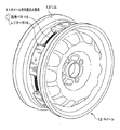
図1に示すように、本実施の形態に係るホイール用共振防止器具11は、ホイール12のリム13の外周面を巻回するように配置される環状体である。
【0014】
このホイール用共振防止器具11は、図2を併せて参照すると明らかなように、リム13のウエル14の底面をその周面に沿うように配置される複数のレゾネータ16と、隣り合うレゾネータ16同士を連結する弦巻バネ15とを備えている。なお、レゾネータ16は、特許請求の範囲にいう「共鳴消音器」に相当し、弦巻バネ15は、特許請求の範囲にいう「弾性連結部材」に相当する。
【0015】
レゾネータ16は、後記するようにヘルムホルツ共鳴消音器として機能するものであり、図3(a)及び図3(b)に示すように、その内部に気室17を有する箱状体である。この箱状体の天井部には、気室17の内外を連通する連通孔18が形成されている。この連通孔18は、レゾネータ16の表面の開口部19から気室17に向かって延びる首部21で取り囲まれている。
【0016】
このようなレゾネータ16の両端部のそれぞれには、弦巻バネ15(図2参照)の一端が取り付けられる連結部20が形成されている。本実施の形態では、この連結部20は、貫通孔20aを有する切片で構成されている。
【0017】
このレゾネータ16は、図4に示すように、タイヤ23の空気室24内における気柱共鳴周波数fTと後記式(1)で示されるレゾネータ16の共鳴周波数fRが一致するように、開口部19の面積S、気室17の体積V、首部21の長さL及びホイール12(図2参照)の周方向における気室17の長さDが規定されているヘルムホルツ共鳴消音器である。なお、式(1)中、Cはタイヤ23の空気室24における音速を表し、αは、図5に示す補正係数であって、タイヤ23の空気室24における気柱の単位長さあたりの気室17(図3(b)参照)の長さDで定義される「気室17の長さ比」(図5参照)に関連づけられた変数である。
【0018】
【数1】
【0019】
すなわち、このレゾネータ16は、前記式(1)及び図5を満足する範囲内で、開口部19の面積S、気室17の体積V、首部21の長さL及び気室17の長さDをそれぞれ適宜に設定することによって、周波数fTのタイヤの共振を防止するようになっている。
【0020】
本実施の形態では、このレゾネータ16が弾性ゴムで構成されているとともに、ホイール用共振防止器具11は、その周長が、このホイール用共振防止器具11に負荷をかけない状態(レゾネータ16及び弦巻バネ15が伸びていない状態)で、ウエル14(図2参照)の底面の周長未満に設定されている。このホイール用共振防止器具11におけるレゾネータ16の個数は、2以上であればよい。
【0021】
弦巻バネ15は、図6に示すように、その両端部にそれぞれ連結部20の貫通孔20a(図3(b)参照)に掛けられる鉤15aを備えている。
【0022】
次に、ホイール12への本実施の形態に係るホイール用共振防止器具11の組み付け方法について適宜図面を参照しながら説明する。
【0023】
参照する図面において、図7は、ホイール用共振防止器具の組み付け方法の説明図である。
【0024】
このホイール用共振防止器具11の組み付けは、図7に示すように、環状のホイール用共振防止器具11が、リムフランジ22を越えることができる程度にその周長を広げ、そして、リムフランジ22を越えさせてホイール用共振防止器具11をウエル14の底面に配置するだけで終了する。
【0025】
そして、ウエル14の底面に配置されたホイール用共振防止器具11は、その周長がウエル14の底面の周長未満に設定されているので、レゾネータ16が弦巻バネ15の緊縮力によってウエル14の方向に向かう付勢力でウエル14の底面に組み付けられる。また、弾性材料で構成されているレゾネータ16は、前記した緊縮力で湾曲することによってウエル14の底面に沿うように配置される。
【0026】
このようにして組み付けられたホイール用共振防止器具11のレゾネータ16は、前記式(1)で規定される開口部19の面積S、気室17の体積V及び首部21の長さL並びに補正係数α(図5参照)及びタイヤ23の気柱の長さから導かれる気室17の長さDで設計されているので、タイヤ23の空気室24内における気柱共鳴が防止されてロードノイズが低減される。
【0027】
このような本実施の形態に係るホイール用共振防止器具11では、タイヤ23(図4参照)の取り付けや取り外しに際して、タイヤ23のビード部や工具がレゾネータ16に干渉しても、弦巻バネ15が伸縮することによって、レゾネータ16の配置位置が可逆的に変位する。また、弾性材料からなるレゾネータ16は、タイヤ23のビード部や工具が干渉すると弾性変形する。その結果、レゾネータ16は、タイヤ23の取り付けや取り外しの障害にならない。
【0028】
また、本実施の形態に係るホイール用共振防止器具11によれば、このホイール用共振防止器具11をウエル14に嵌め込むだけで容易にタイヤの気柱共鳴を防止するホイール12を製造することができる。
【0029】
また、本実施の形態に係るホイール用共振防止器具11によれば、弦巻バネ15の緊縮力でホイール用共振防止器具11が組み付けられているので、従来のホイールのように、他の部材(蓋部材等)を固着して既存のホイールの構造に変更を加える必要がない。したがって、ホイール用共振防止器具11を取り外すだけで、もとのホイール12に容易に復元することができる。
【0030】
また、本実施の形態に係るホイール用共振防止器具11によれば、レゾネータ16同士が弦巻バネ15で連結されているので、このホイール用共振防止器具11の周長を容易に広げることができる。したがって、ウエル14の底面にホイール用共振防止器具11を配置する際に、ホイール用共振防止器具11を容易にリムフランジ22を越えさせてウエル14の底面に配置することができる。
【0031】
また、本実施の形態に係るホイール用共振防止器具11によれば、ホイール用共振防止器具11がウエル14の底面に配置されると、弦巻バネ15の緊縮力でホイール用共振防止器具11がウエル14の底面に組み付けられるので、ホイール用共振防止器具11の組み付けに、溶接材料や接着剤といった固着材料を要しない。その結果、従来のホイールのように、固着材料がウエル14上で不均一に分布して、ホイール12のアンバランス量が増大することは避けられる。したがって、このホイール用共振防止器具11によれば、ホイールバランスの調整を簡単に行うことができる。
【0032】
また、本実施の形態に係るホイール用共振防止器具11によれば、タイヤ23のサイズの違いによって共鳴周波数が変化しても、前記式(1)に基づいて、ホイール用共振防止器具11のレゾネータ16の設計を変更すれば、リム13の形状によってホイール用共振防止器具11の形状が限定されることなく、様々な形状のホイール用共振防止器具11を製造することができる。
【0033】
以上、本発明のホイール用共振防止器具を実施の形態に基づいて具体的に説明したが、本発明は、この実施の形態に何ら制限されるものではない。
【0034】
例えば、本実施の形態では、環状のホイール用共振防止器具11を例示したが、本発明はこれに限定されるものではなく、帯状体であって、その両端にこれら端同士を連結する連結具を有するものであってもよい。
【0035】
また、本実施の形態に係るホイール用共振防止器具11は、底部を有すレゾネータ16(図3(b)参照)を備えているが、本発明はこれに限定されるものではなく、このレゾネータ16に代えて、例えば図8に示すように、レゾネータ25の底が、気室17の平面形状と同じ形状で開口しているものであってもよい。このレゾネータ25を使用したホイール用共振防止器具は、レゾネータ25の気室17の開口部26がウエル14(図2参照)の底面と向き合うように配置される。このようにホイール用共振防止器具がウエル14上に配置されることによって、ウエル14の底面で気室17の開口部26が塞がれて、レゾネータ25がヘルムホルツ共鳴消音器として機能する。
【0036】
また、本発明に係るホイール用共振防止器具に使用されるレゾネータは、図9に示すように、ウエル14(図2参照)の底面に沿って延びるように、レゾネータ33からレゾネータ33の周囲に向けて張り出すフランジ32を備えるとともに、このフランジ32に連結部20が形成されていてもよい。このようなレゾネータ33を備えるホイール用共振防止器具によれば、レゾネータ33が、よりウエル14の底面に近接した箇所で弦巻バネ15(図2参照)によって引っ張られるので、レゾネータ33をより安定してウエル14の底面に組み付けることができる。
【0037】
また、本発明に係るホイール用共振防止器具に使用されるレゾネータは、図10に示すように、レゾネータ37の底が、気室17の平面形状と同じ形状で開口しており、そして、ウエル14(図2参照)の底面に沿って延びるようにレゾネータ37からその周囲に向けて張り出すフランジ32を備えるとともに、このフランジ32に連結部20が形成されていてもよい。このレゾネータ37を備えるホイール用共振防止器具によれば、前記レゾネータ25(図8参照)と同様に、開口部38がウエル14の底面で塞がれるので、レゾネータ37をヘルムホルツ共鳴消音器として機能させることができるとともに、前記レゾネータ33(図9参照)を備えるホイール用共振防止器具と同様に、フランジ32に取り付けられた連結部20によって、レゾネータ37をより安定してウエル14の底面に組み付けることができる。
【0038】
また、このレゾネータ37のフランジ32には、図11に示すように、ウエル14の底面と向き合う面にウエル14の底面との密着性を高める密着補助層39を設けてもよい。この密着補助層39の材料としては、例えば、塩化ビニル、塩化ビニリデン、低密度ポリエチレン、弾性ゴム等の樹脂フィルムや樹脂シートが挙げられる。このような密着補助層39を有するレゾネータ37を備えたホイール用共振防止器具は、ウエル14の底面に対するレゾネータ37の密着力がより高められる。また、密着補助層39でウエル14の底面との密着性が高まると、レゾネータ37は、タイヤの共鳴周波数に基づいて設計したレゾネータ37の共鳴消音性能をより確実に発揮することができる。
【0039】
また、本実施の形態で例示したレゾネータ16及び前記レゾネータ25,33,37では、連通孔18をレゾネータ16,25,33,37の天井部に設けているが、本発明は、これらを使用するものに限定されるものではなく、図12に示すように、4方の側壁部のいずれかに連通孔42が形成されたレゾネータ41を使用したものであってもよい。このようなレゾネータ41を備えたホイール用共振防止器具は、レゾネータ41内に水分が凝集したとしても、凝集した水分が連通孔42から排出されるので、レゾネータ41に水分が滞留することはない。なお、このような連通孔42を設けるにあたって、この連通孔42と前記連結部20との位置関係は、レゾネータ16,25,33,37の共振防止効果を阻害しないように配慮しなければならない。
【0040】
また、レゾネータ16,25,33,37は、リム13の外周面(ウエル14の底面)側が一平面に沿うように形成されているが、本発明は、これらを使用するものに限定されるものではなく、リム13の外周面(ウエル14の底面)側がリム13の外周面(ウエル14の底面)に沿うように湾曲して形成されていてもよい。
【0041】
また、本発明のホイール用共振防止器具は、各レゾネータが同一であっても、あるいは異なっていてもよく、例えばレゾネータ16,25,33,37の開口部19の面積S、気室17の体積V、首部21の長さL及び気室17の長さDが異なるものを組み合わせて配設したホイール用共振防止器具であってもよい。このような異なるレゾネータ16,25,33,37を組み合わせて配設したホイール用共振防止器具は、例えばタイヤ23の形状が自動車の走行状態で変化することによってその共振周波数が変動したとしても、その変動に対応して共鳴消音効果を発揮させることができる。
【0042】
また、本実施の形態に係るホイール用共振防止器具11は、弾性連結部材として弦巻バネ15が使用されているが、本発明はこれに限定されるものでなく、弾性ゴムやその他弾性を有する樹脂等からなる弾性連結部材であってもよい。
【0043】
【発明の効果】
本発明のホイール用共振防止器具によれば、タイヤの空気室内における気柱共鳴を防止し、しかもタイヤの取り付け、取り外し及びホイールバランスの調整が簡単なホイールを簡単な工程で製造することができる。
【図面の簡単な説明】
【図1】本実施の形態に係るホイール用共振防止器具が組み付けられたホイールの斜視図である。
【図2】図1のホイール用共振防止器具の部分斜視図であり、一部に切欠部を含む図である。
【図3】図3(a)は、本実施の形態に係るホイール用共振防止器具に使用されるレゾネータの平面図、図3(b)は、図3(a)のA−A線における断面図である。
【図4】タイヤの空気室内に配置された図1のホイール用共振防止器具の模式図である。
【図5】図1のホイール用共振防止器具に使用されるレゾネータの共鳴周波数の計算式における補正係数αと、このレゾネータの気室の長さ比との関係を示すグラフである。
【図6】図1のホイール用共振防止器具に使用される弦巻バネの側面図である。
【図7】ホイール用共振防止器具の組み付け方法を説明する図である。
【図8】他の実施の形態に係るホイール用共振防止器具に使用されるレゾネータの断面図である。
【図9】他の実施の形態に係るホイール用共振防止器具に使用されるレゾネータの断面図である。
【図10】他の実施の形態に係るホイール用共振防止器具に使用されるレゾネータの断面図である。
【図11】他の実施の形態に係るホイール用共振防止器具に使用されるレゾネータの断面図である。
【図12】他の実施の形態に係るホイール用共振防止器具に使用されるレゾネータの斜視図である。
【符号の説明】
11 ホイール用共振防止器具
12 ホイール
16,25,33,37,41 レゾネータ(共鳴消音器)
15 弦巻バネ(弾性連結部材)[0001]
TECHNICAL FIELD OF THE INVENTION
The present invention relates to a wheel on which a tire is mounted, and more particularly, to a wheel resonance preventing device for preventing air column resonance (cavity resonance) in an air chamber of a tire.
[0002]
[Prior art]
2. Description of the Related Art Conventionally, there has been known a wheel that prevents road column resonance in an air chamber of a tire to reduce road noise generated when a vehicle travels (for example, Patent Document 1). In this wheel, an air chamber is formed between the well and the lid member by fixing a lid member made of, for example, a metal plate to the rim so as to cover a peripheral groove formed by the depression of the well of the rim. Have been. In addition, a communication portion (gap, hole, etc.) for communicating the air chamber with the air chamber of the tire is formed on the wheel so that the air chamber forms a resonance muffler when the tire is mounted. Have been.
According to this wheel, since the resonance silencer prevents air column resonance in the air chamber of the tire, road noise is reduced.
[0003]
[Patent Document 1]
JP-A-2002-79802 (see paragraphs (0084) to (0111) and FIGS. 1 to 4)
[0004]
[Problems to be solved by the invention]
However, in this wheel, since the circumferential groove of the rim, that is, the well, is covered with the lid member, this lid member becomes an obstacle, and there is no room for inserting a tool such as a tire lever into the circumferential groove, and mounting and dismounting of the tire. Is extremely difficult.
Further, in this wheel, in order to form the air chamber, a plurality of lid members must be fixed along the above-mentioned peripheral groove, respectively, so that the manufacturing process of the wheel is complicated.
Further, in this wheel, the amount (weight) of a fixing material such as a welding material or an adhesive used for fixing the lid member and the rim is different for each lid member, so that the unbalance amount of the wheel increases. As a result, adjustment of the wheel balance when the tire is mounted becomes complicated.
[0005]
Therefore, the present invention provides a wheel resonance preventing device capable of preventing air column resonance in an air chamber of a tire and manufacturing a wheel in which a tire can be easily mounted, removed, and adjusted in wheel balance by a simple process. The task is to
[0006]
[Means for Solving the Problems]
In order to solve the above-mentioned problem, the resonance preventing device for a wheel according to claim 1, wherein a plurality of resonance silencers arranged so as to be arranged in a circumferential direction of the wheel and an elasticity for connecting adjacent resonance silencers to each other. And a connecting member.
[0007]
In this device for preventing resonance of a wheel, when the device for preventing resonance of a wheel is mounted on a wheel with an appropriate tension so as to wind around an outer peripheral surface of a rim, each resonance silencer is actuated by a contracting force of each elastic connecting member. It is urged toward the outer peripheral surface of the rim. As a result, a plurality of resonance silencers can be easily mounted on the outer peripheral surface of the rim without using a bonding material.
[0008]
In addition, even when a bead portion or a tool of the tire interferes with the resonance silencer when mounting or dismounting the tire, the position of the resonance silencer is reversibly displaced by expansion and contraction of the elastic connecting member. The container does not hinder tire installation or removal.
[0009]
According to such a resonance preventing device for a wheel, a wheel for a vehicle is provided, wherein the resonance preventing device for a wheel is wound around an outer peripheral surface of a rim.
[0010]
In such a vehicle wheel, since the resonance silencer prevents air column resonance in the air chamber of the tire, road noise when the vehicle travels is reduced.
[0011]
BEST MODE FOR CARRYING OUT THE INVENTION
Next, a resonance preventing device for a wheel according to an embodiment of the present invention will be described with reference to the drawings as appropriate.
[0012]
In the drawings to be referred to, FIG. 1 is a perspective view of a wheel to which a resonance preventing device for a wheel according to the present embodiment is assembled, FIG. 2 is a partial perspective view of the resonance preventing device for a wheel of FIG. 1, and FIG. ) Is a plan view of a resonator used in the wheel resonance preventing device of FIG. 1, FIG. 3B is a cross-sectional view taken along line AA of FIG. 3A, and FIG. FIG. 5 is a schematic diagram of the arranged wheel resonance preventing device of FIG. 1, FIG. 5 is a frequency correction diagram (graph) of the resonator used in the wheel resonance preventing device of FIG. 1, and FIG. It is a top view of a helical spring used for a resonance prevention instrument.
[0013]
As shown in FIG. 1, the resonance preventing device for a wheel 11 according to the present embodiment is an annular body arranged so as to wind around the outer peripheral surface of the rim 13 of the wheel 12.
[0014]
As is apparent from FIG. 2, the resonance preventing device 11 for a wheel includes a plurality of resonators 16 arranged so that the bottom surface of the well 14 of the rim 13 is arranged along the peripheral surface thereof, and a pair of adjacent resonators 16. And a helical spring 15 for connecting the two. The resonator 16 corresponds to a "resonant silencer" in the claims, and the helical spring 15 corresponds to an "elastic connecting member" in the claims.
[0015]
The resonator 16 functions as a Helmholtz resonance silencer as described later, and is a box-shaped body having an air chamber 17 therein as shown in FIGS. 3 (a) and 3 (b). A communication hole 18 communicating between the inside and outside of the air chamber 17 is formed in the ceiling of the box-shaped body. The communication hole 18 is surrounded by a neck 21 extending from the opening 19 on the surface of the resonator 16 toward the air chamber 17.
[0016]
A connecting portion 20 to which one end of the helical spring 15 (see FIG. 2) is attached is formed at each of both ends of the resonator 16. In the present embodiment, the connecting portion 20 is configured by a section having a through hole 20a.
[0017]
As shown in FIG. 4, the resonator 16 has an opening so that the air column resonance frequency f T in the air chamber 24 of the tire 23 and the resonance frequency f R of the resonator 16 represented by the following equation (1) match. This is a Helmholtz resonance silencer in which the area S of the air chamber 19, the volume V of the air chamber 17, the length L of the neck 21 and the length D of the air chamber 17 in the circumferential direction of the wheel 12 (see FIG. 2) are defined. In Expression (1), C represents the sound velocity in the air chamber 24 of the tire 23, α is the correction coefficient shown in FIG. 5, and is the air velocity per unit length of the air column in the air chamber 24 of the tire 23. This is a variable associated with the “length ratio of the air chamber 17” (see FIG. 5) defined by the length D of the chamber 17 (see FIG. 3B).
[0018]
(Equation 1)
[0019]
That is, the resonator 16 has an area S of the opening 19, a volume V of the air chamber 17, a length L of the neck portion 21, and a length D of the air chamber 17 within a range satisfying the expression (1) and FIG. the by setting appropriately respectively, so as to prevent the resonance of the tire of the frequency f T.
[0020]
In the present embodiment, the resonator 16 is made of elastic rubber, and the circumference of the wheel resonance preventing device 11 is in a state where no load is applied to the wheel resonance preventing device 11 (the resonator 16 and the helical winding). In a state where the spring 15 is not extended), it is set to be less than the circumferential length of the bottom surface of the well 14 (see FIG. 2). The number of resonators 16 in the wheel resonance preventing device 11 may be two or more.
[0021]
As shown in FIG. 6, the helical spring 15 has hooks 15a at both ends thereof which are hooked on through holes 20a (see FIG. 3B) of the connecting portion 20, respectively.
[0022]
Next, a method of assembling the wheel resonance preventing device 11 according to the present embodiment to the wheel 12 will be described with reference to the drawings as appropriate.
[0023]
In the drawings to be referred to, FIG. 7 is an explanatory view of an assembling method of the wheel resonance preventing device.
[0024]
As shown in FIG. 7, the assembling of the wheel anti-resonance device 11 is such that the annular wheel anti-resonance device 11 extends its perimeter so as to be able to pass over the rim flange 22, and The operation is completed only by disposing the wheel resonance preventing device 11 on the bottom surface of the well 14 by moving it over.
[0025]
Since the peripheral length of the wheel resonance preventing device 11 arranged on the bottom surface of the well 14 is set to be less than the peripheral length of the bottom surface of the well 14, the resonator 16 is caused to contract by the contraction force of the helical spring 15. It is assembled to the bottom surface of the well 14 by the urging force directed in the direction. Further, the resonator 16 made of an elastic material is arranged along the bottom surface of the well 14 by being curved by the contraction force described above.
[0026]
The resonator 16 of the wheel anti-resonance instrument 11 assembled in this manner has the area S of the opening 19, the volume V of the air chamber 17, the length L of the neck 21, and the correction coefficient defined by the above equation (1). α (see FIG. 5) and the length D of the air chamber 17 derived from the length of the air column of the tire 23, the air column resonance in the air chamber 24 of the tire 23 is prevented, and road noise is reduced. Reduced.
[0027]
In such a wheel resonance preventing device 11 according to the present embodiment, when the tire 23 (see FIG. 4) is attached or detached, even if the bead portion or the tool of the tire 23 interferes with the resonator 16, the helical spring 15 is moved. Due to the expansion and contraction, the arrangement position of the resonator 16 is reversibly displaced. The resonator 16 made of an elastic material is elastically deformed when a bead portion of the tire 23 or a tool interferes. As a result, the resonator 16 does not hinder the attachment or removal of the tire 23.
[0028]
Further, according to the resonance preventing device for a wheel 11 according to the present embodiment, it is possible to easily manufacture the wheel 12 that prevents the air column resonance of the tire by simply fitting the resonance preventing device for a wheel 11 into the well 14. it can.
[0029]
Further, according to the wheel resonance preventing device 11 according to the present embodiment, since the wheel resonance preventing device 11 is assembled by the contraction force of the helical spring 15, other members (lids) like the conventional wheel are used. It is not necessary to fix members or the like to change the structure of the existing wheel. Therefore, the wheel 12 can be easily restored to the original wheel 12 only by removing the wheel resonance preventing device 11.
[0030]
Further, according to the resonance preventing device 11 for a wheel according to the present embodiment, since the resonators 16 are connected to each other by the helical spring 15, the circumference of the resonance preventing device 11 for a wheel can be easily widened. Therefore, when arranging the wheel resonance preventing device 11 on the bottom surface of the well 14, the wheel resonance preventing device 11 can easily be disposed on the bottom surface of the well 14 over the rim flange 22.
[0031]
Further, according to the wheel resonance preventing device 11 according to the present embodiment, when the wheel resonance preventing device 11 is disposed on the bottom surface of the well 14, the wheel resonance preventing device 11 is Since it is assembled to the bottom surface of the mounting member 14, a bonding material such as a welding material or an adhesive is not required for assembling the resonance preventing device 11 for a wheel. As a result, it is possible to prevent the bonding material from being unevenly distributed on the well 14 and increasing the amount of unbalance of the wheel 12 as in the conventional wheel. Therefore, according to the wheel resonance preventing device 11, it is possible to easily adjust the wheel balance.
[0032]
Further, according to the resonance preventing device for a wheel 11 according to the present embodiment, even if the resonance frequency changes due to a difference in the size of the tire 23, the resonator of the resonance preventing device for a wheel 11 based on the equation (1). If the design of 16 is changed, the shape of the wheel resonance preventing device 11 is not limited by the shape of the rim 13, and the wheel resonance preventing device 11 of various shapes can be manufactured.
[0033]
As described above, the resonance preventing device for a wheel according to the present invention has been specifically described based on the embodiment. However, the present invention is not limited to this embodiment.
[0034]
For example, in the present embodiment, the ring-shaped wheel resonance preventing device 11 is exemplified, but the present invention is not limited to this, and is a band-shaped body, and a connecting tool for connecting these ends to both ends thereof. May be provided.
[0035]
Further, the resonance preventing device for a wheel 11 according to the present embodiment includes a resonator 16 having a bottom (see FIG. 3B), but the present invention is not limited to this, and the resonator 16 is not limited thereto. Instead of 16, for example, as shown in FIG. 8, the bottom of the resonator 25 may be open in the same shape as the plane shape of the air chamber 17. The device for preventing resonance of a wheel using the resonator 25 is arranged such that the opening 26 of the air chamber 17 of the resonator 25 faces the bottom surface of the well 14 (see FIG. 2). By arranging the wheel resonance preventing device on the well 14 in this manner, the opening 26 of the air chamber 17 is closed at the bottom surface of the well 14, and the resonator 25 functions as a Helmholtz resonance muffler.
[0036]
Also, as shown in FIG. 9, the resonator used in the wheel resonance preventing device according to the present invention extends from the resonator 33 toward the periphery of the resonator 33 so as to extend along the bottom surface of the well 14 (see FIG. 2). And a connecting portion 20 may be formed on the flange 32. According to the resonance preventing device for a wheel including such a resonator 33, the resonator 33 is pulled by the helical spring 15 (see FIG. 2) at a position closer to the bottom surface of the well 14, so that the resonator 33 is more stably provided. It can be assembled to the bottom of the well 14.
[0037]
Further, as shown in FIG. 10, the resonator used in the resonance prevention device for a wheel according to the present invention has the bottom of the resonator 37 opened in the same shape as the plane shape of the air chamber 17 and the well 14. A flange 32 may be provided extending from the resonator 37 toward the periphery thereof so as to extend along the bottom surface of the flange (see FIG. 2), and the connecting portion 20 may be formed on the flange 32. According to the resonance prevention device for a wheel including the resonator 37, the opening 38 is closed by the bottom surface of the well 14 similarly to the resonator 25 (see FIG. 8), so that the resonator 37 functions as a Helmholtz resonance silencer. In addition to the above, the resonator 37 can be more stably assembled to the bottom surface of the well 14 by the connecting portion 20 attached to the flange 32, similarly to the wheel resonance prevention device including the resonator 33 (see FIG. 9). it can.
[0038]
As shown in FIG. 11, the flange 32 of the resonator 37 may be provided with an adhesion auxiliary layer 39 on the surface facing the bottom surface of the well 14 for improving the adhesion to the bottom surface of the well 14. Examples of the material of the adhesion auxiliary layer 39 include a resin film and a resin sheet such as vinyl chloride, vinylidene chloride, low-density polyethylene, and elastic rubber. In the wheel resonance preventing device including the resonator 37 having the adhesion auxiliary layer 39, the adhesion of the resonator 37 to the bottom surface of the well 14 is further increased. In addition, when the adhesion to the bottom surface of the well 14 is increased by the adhesion auxiliary layer 39, the resonator 37 can more reliably exhibit the resonance silencing performance of the resonator 37 designed based on the resonance frequency of the tire.
[0039]
In the resonator 16 and the resonators 25, 33, and 37 exemplified in the present embodiment, the communication holes 18 are provided in the ceilings of the resonators 16, 25, 33, and 37, but the present invention uses them. However, the present invention is not limited to this, and as shown in FIG. 12, a resonator 41 having a communication hole 42 formed in one of four side walls may be used. In such a device for preventing resonance of a wheel provided with such a resonator 41, even if water is agglomerated in the resonator 41, since the agglomerated water is discharged from the communication hole 42, the water does not stay in the resonator 41. In providing such a communication hole 42, care must be taken so that the positional relationship between the communication hole 42 and the connecting portion 20 does not hinder the resonance preventing effects of the resonators 16, 25, 33, and 37.
[0040]
In addition, the resonators 16, 25, 33, and 37 are formed so that the outer peripheral surface of the rim 13 (the bottom surface of the well 14) is along one plane, but the present invention is limited to those using these. Instead, the outer peripheral surface of the rim 13 (the bottom surface of the well 14) may be curved along the outer peripheral surface of the rim 13 (the bottom surface of the well 14).
[0041]
Moreover, in the resonance preventing device for a wheel according to the present invention, each resonator may be the same or different. For example, the area S of the opening 19 of each of the resonators 16, 25, 33, and 37, the volume of the air chamber 17, and the like. V, a resonance preventing device for a wheel, which is provided by combining components having different lengths L, L, and D, of the air chamber 17 may be used. Such a resonance preventing device for a wheel in which different resonators 16, 25, 33, and 37 are arranged in combination, for example, even if its resonance frequency fluctuates due to a change in the shape of the tire 23 in a running state of the automobile, is not necessary. A resonance silencing effect can be exhibited in response to the fluctuation.
[0042]
Further, in the wheel resonance preventing device 11 according to the present embodiment, the helical spring 15 is used as the elastic connecting member, but the present invention is not limited to this, and elastic rubber or other resin having elasticity is used. It may be an elastic connecting member made of the same.
[0043]
【The invention's effect】
ADVANTAGE OF THE INVENTION According to the resonance prevention apparatus for wheels of this invention, the air column resonance in the air chamber of a tire can be prevented, and also the attachment and detachment of a tire, and the wheel whose adjustment of a wheel balance is easy can be manufactured by a simple process.
[Brief description of the drawings]
FIG. 1 is a perspective view of a wheel to which a resonance preventing device for a wheel according to the present embodiment is assembled.
FIG. 2 is a partial perspective view of the device for preventing resonance of a wheel of FIG. 1 and partially including a cutout portion.
FIG. 3A is a plan view of a resonator used in the wheel resonance preventing device according to the present embodiment, and FIG. 3B is a cross-sectional view taken along line AA in FIG. FIG.
4 is a schematic view of the resonance preventing device for a wheel of FIG. 1 arranged in an air chamber of a tire.
5 is a graph showing a relationship between a correction coefficient α in a formula for calculating a resonance frequency of a resonator used in the resonance preventing device for a wheel of FIG. 1 and a length ratio of an air chamber of the resonator.
FIG. 6 is a side view of a helical spring used in the resonance preventing device for a wheel of FIG. 1;
FIG. 7 is a diagram illustrating a method of assembling the resonance preventing device for a wheel.
FIG. 8 is a cross-sectional view of a resonator used in a resonance preventing device for a wheel according to another embodiment.
FIG. 9 is a cross-sectional view of a resonator used in a resonance preventing device for a wheel according to another embodiment.
FIG. 10 is a sectional view of a resonator used in a wheel resonance preventing device according to another embodiment.
FIG. 11 is a cross-sectional view of a resonator used for a wheel resonance preventing device according to another embodiment.
FIG. 12 is a perspective view of a resonator used in a resonance preventing device for a wheel according to another embodiment.
[Explanation of symbols]
11 Wheel resonance prevention device 12 Wheels 16, 25, 33, 37, 41 Resonator (resonance silencer)
15 Spring wound (elastic connecting member)