JP2004303481A - Light-emitting element and emission display device - Google Patents
Light-emitting element and emission display device Download PDFInfo
- Publication number
- JP2004303481A JP2004303481A JP2003092535A JP2003092535A JP2004303481A JP 2004303481 A JP2004303481 A JP 2004303481A JP 2003092535 A JP2003092535 A JP 2003092535A JP 2003092535 A JP2003092535 A JP 2003092535A JP 2004303481 A JP2004303481 A JP 2004303481A
- Authority
- JP
- Japan
- Prior art keywords
- light
- electrode
- layer
- emitting element
- display device
- Prior art date
- Legal status (The legal status is an assumption and is not a legal conclusion. Google has not performed a legal analysis and makes no representation as to the accuracy of the status listed.)
- Pending
Links
- 239000000758 substrate Substances 0.000 claims description 25
- 229910052751 metal Inorganic materials 0.000 claims description 14
- 239000002184 metal Substances 0.000 claims description 14
- ZOKXTWBITQBERF-UHFFFAOYSA-N Molybdenum Chemical compound [Mo] ZOKXTWBITQBERF-UHFFFAOYSA-N 0.000 claims description 10
- 239000011733 molybdenum Substances 0.000 claims description 10
- WGLPBDUCMAPZCE-UHFFFAOYSA-N Trioxochromium Chemical compound O=[Cr](=O)=O WGLPBDUCMAPZCE-UHFFFAOYSA-N 0.000 claims description 9
- 229910000423 chromium oxide Inorganic materials 0.000 claims description 9
- 229910000476 molybdenum oxide Inorganic materials 0.000 claims description 3
- 239000010409 thin film Substances 0.000 abstract description 21
- 239000007769 metal material Substances 0.000 abstract description 7
- 239000010410 layer Substances 0.000 description 153
- 238000005401 electroluminescence Methods 0.000 description 34
- 238000002347 injection Methods 0.000 description 25
- 239000007924 injection Substances 0.000 description 25
- 239000000463 material Substances 0.000 description 19
- 238000000605 extraction Methods 0.000 description 8
- 239000011159 matrix material Substances 0.000 description 8
- 150000002894 organic compounds Chemical class 0.000 description 8
- 239000011521 glass Substances 0.000 description 7
- 229910052750 molybdenum Inorganic materials 0.000 description 7
- 230000010287 polarization Effects 0.000 description 6
- 230000017525 heat dissipation Effects 0.000 description 5
- 230000005525 hole transport Effects 0.000 description 4
- 239000011229 interlayer Substances 0.000 description 4
- 238000000034 method Methods 0.000 description 4
- 238000002834 transmittance Methods 0.000 description 4
- 229910052782 aluminium Inorganic materials 0.000 description 3
- 239000003990 capacitor Substances 0.000 description 3
- 238000010586 diagram Methods 0.000 description 3
- 238000001704 evaporation Methods 0.000 description 3
- 230000008020 evaporation Effects 0.000 description 3
- 229910052709 silver Inorganic materials 0.000 description 3
- 239000002356 single layer Substances 0.000 description 3
- 239000004372 Polyvinyl alcohol Substances 0.000 description 2
- 230000007423 decrease Effects 0.000 description 2
- 230000006866 deterioration Effects 0.000 description 2
- 230000000694 effects Effects 0.000 description 2
- 239000010408 film Substances 0.000 description 2
- AMGQUBHHOARCQH-UHFFFAOYSA-N indium;oxotin Chemical compound [In].[Sn]=O AMGQUBHHOARCQH-UHFFFAOYSA-N 0.000 description 2
- 229920002451 polyvinyl alcohol Polymers 0.000 description 2
- 230000002265 prevention Effects 0.000 description 2
- 238000001771 vacuum deposition Methods 0.000 description 2
- ZCYVEMRRCGMTRW-UHFFFAOYSA-N 7553-56-2 Chemical compound [I] ZCYVEMRRCGMTRW-UHFFFAOYSA-N 0.000 description 1
- VYZAMTAEIAYCRO-UHFFFAOYSA-N Chromium Chemical compound [Cr] VYZAMTAEIAYCRO-UHFFFAOYSA-N 0.000 description 1
- 229910019923 CrOx Inorganic materials 0.000 description 1
- 229910004205 SiNX Inorganic materials 0.000 description 1
- 229910004298 SiO 2 Inorganic materials 0.000 description 1
- 230000002411 adverse Effects 0.000 description 1
- 229910045601 alloy Inorganic materials 0.000 description 1
- 239000000956 alloy Substances 0.000 description 1
- 229910021417 amorphous silicon Inorganic materials 0.000 description 1
- 230000005540 biological transmission Effects 0.000 description 1
- 230000015572 biosynthetic process Effects 0.000 description 1
- 229910052804 chromium Inorganic materials 0.000 description 1
- 239000011651 chromium Substances 0.000 description 1
- 239000004020 conductor Substances 0.000 description 1
- 239000007772 electrode material Substances 0.000 description 1
- 238000005530 etching Methods 0.000 description 1
- 230000005283 ground state Effects 0.000 description 1
- 239000012535 impurity Substances 0.000 description 1
- 238000007641 inkjet printing Methods 0.000 description 1
- 229910010272 inorganic material Inorganic materials 0.000 description 1
- 239000011147 inorganic material Substances 0.000 description 1
- 239000011630 iodine Substances 0.000 description 1
- 229910052740 iodine Inorganic materials 0.000 description 1
- 238000003475 lamination Methods 0.000 description 1
- 238000005224 laser annealing Methods 0.000 description 1
- 239000004973 liquid crystal related substance Substances 0.000 description 1
- 239000011368 organic material Substances 0.000 description 1
- 230000003647 oxidation Effects 0.000 description 1
- 238000007254 oxidation reaction Methods 0.000 description 1
- 238000000206 photolithography Methods 0.000 description 1
- 229920003023 plastic Polymers 0.000 description 1
- 229910021420 polycrystalline silicon Inorganic materials 0.000 description 1
- 230000000630 rising effect Effects 0.000 description 1
- 238000004528 spin coating Methods 0.000 description 1
- ODHXBMXNKOYIBV-UHFFFAOYSA-N triphenylamine Chemical class C1=CC=CC=C1N(C=1C=CC=CC=1)C1=CC=CC=C1 ODHXBMXNKOYIBV-UHFFFAOYSA-N 0.000 description 1
- 238000007738 vacuum evaporation Methods 0.000 description 1
- YVTHLONGBIQYBO-UHFFFAOYSA-N zinc indium(3+) oxygen(2-) Chemical compound [O--].[Zn++].[In+3] YVTHLONGBIQYBO-UHFFFAOYSA-N 0.000 description 1
Images


Classifications
-
- H—ELECTRICITY
- H10—SEMICONDUCTOR DEVICES; ELECTRIC SOLID-STATE DEVICES NOT OTHERWISE PROVIDED FOR
- H10K—ORGANIC ELECTRIC SOLID-STATE DEVICES
- H10K50/00—Organic light-emitting devices
- H10K50/80—Constructional details
- H10K50/86—Arrangements for improving contrast, e.g. preventing reflection of ambient light
- H10K50/865—Arrangements for improving contrast, e.g. preventing reflection of ambient light comprising light absorbing layers, e.g. light-blocking layers
-
- E—FIXED CONSTRUCTIONS
- E05—LOCKS; KEYS; WINDOW OR DOOR FITTINGS; SAFES
- E05F—DEVICES FOR MOVING WINGS INTO OPEN OR CLOSED POSITION; CHECKS FOR WINGS; WING FITTINGS NOT OTHERWISE PROVIDED FOR, CONCERNED WITH THE FUNCTIONING OF THE WING
- E05F15/00—Power-operated mechanisms for wings
- E05F15/70—Power-operated mechanisms for wings with automatic actuation
- E05F15/73—Power-operated mechanisms for wings with automatic actuation responsive to movement or presence of persons or objects
-
- E—FIXED CONSTRUCTIONS
- E05—LOCKS; KEYS; WINDOW OR DOOR FITTINGS; SAFES
- E05D—HINGES OR SUSPENSION DEVICES FOR DOORS, WINDOWS OR WINGS
- E05D15/00—Suspension arrangements for wings
- E05D15/06—Suspension arrangements for wings for wings sliding horizontally more or less in their own plane
- E05D15/0621—Details, e.g. suspension or supporting guides
- E05D15/0626—Details, e.g. suspension or supporting guides for wings suspended at the top
- E05D15/063—Details, e.g. suspension or supporting guides for wings suspended at the top on wheels with fixed axis
-
- E—FIXED CONSTRUCTIONS
- E05—LOCKS; KEYS; WINDOW OR DOOR FITTINGS; SAFES
- E05F—DEVICES FOR MOVING WINGS INTO OPEN OR CLOSED POSITION; CHECKS FOR WINGS; WING FITTINGS NOT OTHERWISE PROVIDED FOR, CONCERNED WITH THE FUNCTIONING OF THE WING
- E05F15/00—Power-operated mechanisms for wings
- E05F15/60—Power-operated mechanisms for wings using electrical actuators
- E05F15/603—Power-operated mechanisms for wings using electrical actuators using rotary electromotors
- E05F15/632—Power-operated mechanisms for wings using electrical actuators using rotary electromotors for horizontally-sliding wings
-
- E—FIXED CONSTRUCTIONS
- E05—LOCKS; KEYS; WINDOW OR DOOR FITTINGS; SAFES
- E05Y—INDEXING SCHEME RELATING TO HINGES OR OTHER SUSPENSION DEVICES FOR DOORS, WINDOWS OR WINGS AND DEVICES FOR MOVING WINGS INTO OPEN OR CLOSED POSITION, CHECKS FOR WINGS AND WING FITTINGS NOT OTHERWISE PROVIDED FOR, CONCERNED WITH THE FUNCTIONING OF THE WING
- E05Y2201/00—Constructional elements; Accessories therefore
- E05Y2201/60—Suspension or transmission members; Accessories therefore
- E05Y2201/622—Suspension or transmission members elements
- E05Y2201/684—Rails
-
- E—FIXED CONSTRUCTIONS
- E05—LOCKS; KEYS; WINDOW OR DOOR FITTINGS; SAFES
- E05Y—INDEXING SCHEME RELATING TO HINGES OR OTHER SUSPENSION DEVICES FOR DOORS, WINDOWS OR WINGS AND DEVICES FOR MOVING WINGS INTO OPEN OR CLOSED POSITION, CHECKS FOR WINGS AND WING FITTINGS NOT OTHERWISE PROVIDED FOR, CONCERNED WITH THE FUNCTIONING OF THE WING
- E05Y2201/00—Constructional elements; Accessories therefore
- E05Y2201/60—Suspension or transmission members; Accessories therefore
- E05Y2201/622—Suspension or transmission members elements
- E05Y2201/688—Rollers
-
- E—FIXED CONSTRUCTIONS
- E05—LOCKS; KEYS; WINDOW OR DOOR FITTINGS; SAFES
- E05Y—INDEXING SCHEME RELATING TO HINGES OR OTHER SUSPENSION DEVICES FOR DOORS, WINDOWS OR WINGS AND DEVICES FOR MOVING WINGS INTO OPEN OR CLOSED POSITION, CHECKS FOR WINGS AND WING FITTINGS NOT OTHERWISE PROVIDED FOR, CONCERNED WITH THE FUNCTIONING OF THE WING
- E05Y2900/00—Application of doors, windows, wings or fittings thereof
- E05Y2900/10—Application of doors, windows, wings or fittings thereof for buildings or parts thereof
- E05Y2900/13—Application of doors, windows, wings or fittings thereof for buildings or parts thereof characterised by the type of wing
- E05Y2900/132—Doors
-
- H—ELECTRICITY
- H10—SEMICONDUCTOR DEVICES; ELECTRIC SOLID-STATE DEVICES NOT OTHERWISE PROVIDED FOR
- H10K—ORGANIC ELECTRIC SOLID-STATE DEVICES
- H10K50/00—Organic light-emitting devices
- H10K50/80—Constructional details
- H10K50/805—Electrodes
-
- H—ELECTRICITY
- H10—SEMICONDUCTOR DEVICES; ELECTRIC SOLID-STATE DEVICES NOT OTHERWISE PROVIDED FOR
- H10K—ORGANIC ELECTRIC SOLID-STATE DEVICES
- H10K59/00—Integrated devices, or assemblies of multiple devices, comprising at least one organic light-emitting element covered by group H10K50/00
- H10K59/10—OLED displays
- H10K59/12—Active-matrix OLED [AMOLED] displays
-
- H—ELECTRICITY
- H10—SEMICONDUCTOR DEVICES; ELECTRIC SOLID-STATE DEVICES NOT OTHERWISE PROVIDED FOR
- H10K—ORGANIC ELECTRIC SOLID-STATE DEVICES
- H10K59/00—Integrated devices, or assemblies of multiple devices, comprising at least one organic light-emitting element covered by group H10K50/00
- H10K59/80—Constructional details
- H10K59/805—Electrodes
Abstract
Description
【0001】
【発明の属する技術分野】
本発明は、表示装置などに用いられる発光素子の構造、特にその背面側の構造に関する。
【0002】
【従来の技術】
発光素子として、最近、エレクトロルミネッセンス(Electroluminescence:以下EL)素子が注目されており、このEL素子を用いた表示装置は、液晶表示装置(LCD)やCRTなどの表示装置に代わる装置等として研究が進められている。
【0003】
EL素子の内、発光材料として有機化合物を用いたいわゆる有機EL素子は、正孔注入電極(陽極)と電子注入電極(陰極)の間に有機発光分子を含む発光素子層を挟んだ構造を備える。より具体的には、透明なガラス基板上に、正孔注入電極としてITO(Indium Tin Oxide)からなる透明導電層が形成され、正孔注入電極の上に単層又は多層からなる発光素子層が積層され、この発光素子層の上に電子注入電極としてAl、Ag、MgAgなどの不透明な金属電極が形成されている。
【0004】
このような構造において、正孔注入電極から注入される正孔と、電子注入電極から注入される電子が、発光素子層中で再結合し、層内に含まれる有機発光分子が励起され、この分子が基底状態に戻る際に放射される光を透明な正孔注入電極及びガラス基板を透過させ、外部に取り出している。
【0005】
ここで、光射出側(観察側)に対して背面側に位置する金属電極は、通常、反射性の高い金属材料が採用されるため、その発光素子側の表面において、基板及び透明電極を通過して素子内に入射してくる外光の反射が発生する。この外光の反射は、表示装置において特に黒表示をする場合に、コントラストを低下させる大きな原因となり、また、金属電極の観察面(反射面)に周囲の像が映り込み、表示画像の視認性が低下するなど、表示品質の低下が起きる。
【0006】
このような金属電極の反射による表示品質低下を防止する簡便な方法として、LCDにおいて用いられている偏光層を透明なガラス基板や、透明な正孔注入電極のガラス基板側、即ち素子の観察面(光取り出し面)側に配置することが、例えば下記特許文献1に開示されている。
【0007】
【特許文献1】
特開平7−142170号公報
【発明が解決しようとする課題】
上記特許文献1に記載されているように、素子の光取り出し面側に偏光層を配置することで、素子外部から素子内に入射し、背面側の金属電極で反射されて再び素子から射出される光をこの偏光層で遮蔽することができる。
【0008】
即ち、素子外部から偏光層を通過して素子内に入射した光は、偏光層の偏光方向に平行な直線偏光であり、この直線偏光が金属電極で反射されるとその偏光方向が90°逆になる。従って、金属電極で反射された光の偏光方向は、偏光層の偏光方向異なるため、偏光層を通過できず遮断されるためである。
【0009】
このように偏光層を設けることで、光取り出し面に反射光が射出されることが防止され、コントラスト低下を抑制することができる。しかし、素子の光取り出し側に偏光層が存在するため、発光層からの光も偏光層を通過しなければ外部に取り出すことができない。偏光板は、発光層での発光光のうち偏光層の偏光方向に平行な偏光方向の光しか通過させないので、発光光の多くがこの偏光層を通過できずに吸収されることとなる。従って、偏光層を設けることで発光光の利用効率が大幅に低下してしまい、素子外に実際に取り出す光量を増やすためには、有機EL素子の発光輝度を増大させる必要があり、そのためには正孔注入電極と電子注入電極間(発光素子層)に流す電流量を増やなければならない。
【0010】
しかし、有機EL素子では、発光分子などの有機化合物を含む発光素子層に流す電流が多いほど、輝度低下速度が大きくなって素子寿命を早めてしまうという問題がある。一方で、電流量を増やさずに高い輝度を得るためには高効率発光が可能な新規有機発光材料を、また、電流量が増大しても長寿命な素子を実現するためには耐久性の高い新規有機発光材料の開発を待たねばならない。
【0011】
上記課題に対し、本発明は、高コントラストかつ長寿命で高輝度の発光素子及び発光表示装置を提供する。
【0012】
【課題を解決するための手段】
本発明は、第1電極と第2電極との間に発光素子層を備えた発光素子において、前記第1電極と前記第2電極の内、一方は光射出側電極として、外部への光射出側に配置され、該光射出側電極の背面側に位置する背面側電極は、発光素子層側から入射する光を一部透過する半透過電極より構成され、該半透過電極の背面側に反射防止層が設けられている。
【0013】
本発明の他の観点では、第1電極と第2電極との間に発光素子層を備えて構成される発光素子を備える発光表示装置であって、前記第1電極は、装置の外部への光射出側に配置される透明基板の上に形成され、前記発光素子層から射出される光を透過可能な電極であり、前記第2電極は、前記発光素子層を挟んで前記第1電極と対向するように前記第1電極の背面側に形成され、前記発光素子層側から入射する光を一部透過する半透過電極であり、前記第2電極の背面側に反射防止層が設けられている。
【0014】
本発明の他の観点では、陽極と陰極との間に発光素子層を備えるエレクトロルミネッセンス素子を備える表示装置において、前記陽極は、外部への光射出側となる透明基板の上に形成され、前記発光素子層から射出される光を透過可能な電極を備え、前記陰極は、前記発光素子層を挟んで前記陽極と対向するように該陽極の背面側に形成され、前記発光素子層から射出される光を一部透過可能な半透過電極を備え、前記陰極の背面側には反射防止層が形成されている。
【0015】
このように、発光素子の光射出側電極に対して背面側に位置する背面電極として半透過性の電極を採用し、この背面電極のさらに背面側に低反射層又は反射防止層を設けることで、素子に入射する外光を背面側電極の表面で反射させず透過させ反射率の低い反射防止層で吸収することができる。発光素子層から透明な光射出側電極に進んだ光は、光射出側電極を透過し、また透明基板を透過することができ、最小限の損失で効率的に素子外に光を射出することができる。このため、発光素子層からの発光光の内、背面電極側に進んだ光は、外光と同様反射されずに反射防止層で吸収されるものの、外光の反射によるコントラスト低下が防止でき、背面電極側に進んだ光が損失となること以上にコントラスト向上による表示品質向上、例えば見易くかつ視認される実際の輝度の高い発光素子を実現できる。
【0016】
本発明の他の観点では、上記発光素子又は表示装置において、前記半透過電極には、光を透過可能に薄膜化されている金属層、又は光を通過させる開口を備えた網目状金属層が用いられている。
【0017】
本発明の他の観点では、上記発光素子又は表示装置において、前記半透過電極には、20nm以下の厚さのAg層又はMgAg層が用いられている。
【0018】
このように金属層を薄く又は開口部を設けた構成とすることで、光を透過可能とすると共に電極材料自体を変更することなく採用することができ、電極として必要な機能を発揮させることができる。
【0019】
本発明の他の観点では、上記発光素子又は表示装置において、前記低反射層または反射防止層には、モリブデン又は酸化クロムが用いられている。
【0020】
反射防止層にモリブデンや酸化クロムを採用することで、背面側電極のさらに背面側に容易に表面における光反射率の低い層を形成でき、半透過性の背面電極を透過してきた外光が反射して再び素子から射出させることを防止できる。
【0021】
【発明の実施の形態】
以下、本発明の好適な実施の形態(以下、実施形態)について、図面に基づいて説明する。
【0022】
本発明の実施形態に係る発光素子としては、例えばEL素子が挙げられる。図1は、EL素子を例に本発明の実施形態に係る素子の概略断面構造を示している。基板10としては、ガラスや、プラスチックなどの透明基板が用いられており、この透明基板10の上方にEL素子の各要素が積層されている。この例では、EL素子50は、発光材料として有機化合物を用いた有機EL素子であり、第1電極20と第2電極22との間に、有機化合物を含む発光素子層30が形成されている。
【0023】
図1に示す有機EL素子50では、ITO(Indium Tin Oxide)やIZO(Indium Zinc Oxide)などの透明導電材料からなり、ここでは正孔注入機能を備えた透明電極(光透過性電極、但し光透過性のやや低い半透過性電極でも良い)である第1電極20が、透明基板10の上に直接、又はバッファ層や有機EL素子を駆動するトランジスタ等を介して形成されている。第1電極20の上の発光素子層30は、有機化合物を含む単層又は多層構造を備え、この発光素子層30の上に電子注入機能を備える半透過性の第2電極22が、第1電極20と対向するように形成されている。またこの第2電極22の上層、即ち、観察側となる透明基板10から見て第2電極22の更に背面側に入射光の反射率の低い酸化クロム(CrOx:xは任意の数)層やモリブデン(Mo)層などからなる反射防止層46が形成されている。
【0024】
発光素子層30は、用いられる有機化合物の機能等に応じて様々な構造が採用可能であるが、例えば、発光機能・正孔輸送機能・電子輸送機能の全てを備える有機発光層の単層構造、正孔注入電極(陽極)20側から順に正孔輸送層/発光層/電子輸送層が積層された3層構造などが挙げられる。図1に示す発光素子層30は、正孔注入電極20の上に、CFx等を含む正孔注入層32、NPBなどのトリフェニルアミンの誘導体等を含む正孔輸送層34、目的とする発光色に応じた有機発光分子を含む発光層36、Alq等を含む電子輸送層38、LiF等からなる電子注入層40の積層構造を備える。
【0025】
発光層36は、R,B,G光を得るために、それぞれ適切な材料が用いられている。
【0026】
なお、発光素子層30を、低分子系有機化合物を含む層で構成する場合、各層は例えば真空蒸着法にてそれぞれ所望の厚さに形成することができ、また高分子化合物を含む層によって構成する場合は、インクジェット印刷法や、スピンコート法などを用いて形成することができる。
【0027】
第2電極22は図1の例では、陰極として機能しており、発光素子層30に電子を効率的に注入する機能が求められる。このような電子注入機能の高い材料は、仕事関数が小さく、通常、光透過率の低い金属材料が適している。例えば上記Al、Ag、MgAg合金などが挙げられる。しかし、電極として機能させることを重視し、例えば200nm程度の厚さに形成したAl層やAg層を電極として用いると、発光素子層30側の表面で反射が起き、上述のように、外光の反射によるコントラスト低下が発生する。
【0028】
そこで、本実施形態では、まず、第2電極22に、電子注入材料として適切な例えばAl、Ag、AgMg層を採用する場合、その厚さを例えば5nm〜40nm程度の薄膜とすることで光透過性を確保することができる。例えば、20nm程度の薄膜とすることで、電子注入機能を損なわずに50%以上の光透過性、即ち半透過電極を実現している。Alなどの金属材料は上記発光素子層30の各層と同様に例えば真空蒸着法などによって形成することができ、蒸着時間の制御等により所望の厚さの薄膜となるように精度良く制御することができる。
【0029】
また、Alなどの遮光性の金属材料を第2電極22の材料として用い、かつ半透過性を実現するための他の方法として、図2に示すように金属第2電極22の少なくとも1画素中など単位表示領域内に光の通過可能な開口を備えた網目状(格子状も含む)としてもよい。各開口部は、円、多角形などその形状は特に問わないが、金属層を形成してからフォトリソグラフィなどによって選択的エッチング除去して形成する場合のエッチング残りが少なく、かつ単位領域内における開口面積ができる限り等しいことが表示品質のばらつきを防ぐ等の観点で好ましい。
【0030】
なお、半透過性の第2電極22については、上記金属材料に限られず、特に薄膜化しなくても十分な光透過性を備えた導電性で仕事関数の小さい材料であれば採用することができる。
【0031】
本実施形態では、このような半透過機能を備える第2電極22を覆って上述のように反射防止層46を形成し、第2電極22を透過する光をこの反射防止光46で吸収し反射を防止する。反射防止層46の材料として採用可能な酸化クロムやモリブデンのいずれも、真空蒸着によって第2電極22を形成した後、蒸着源を反射防止材料に変更し、連続して蒸着を行うことで容易に積層形成することができる。ここで、反射防止層46の材料として、モリブデンを採用した場合には反射防止層46の反射率は20%程度以下とすることができ、酸化クロムを採用した場合、5%程度以下とすることができる。
【0032】
ここで、反射防止層46としてどの程度の反射率の材料を選択するかについては、要求輝度や、発光素子層30における発光分子の発光輝度及び発光効率を考慮し、また第2電極22の光透過率も勘案して決定することが好ましい。しかし、コントラスト向上のためには、この反射防止層46の光反射率は、50%未満、より好ましくは30%以下であることが好ましい。第2電極22を透過して反射防止層46に到達する光には、発光素子層30で得られた発光光も含まれており、発光輝度の比較的低い材料を採用している場合や、素子に対する要求輝度が高い場合には、発光光の有効利用が望まれる。従って、ある程度、光(発光光)を反射して素子外に射出できるよう、例えば、20%程度の反射率が得られるモリブデンを反射防止層46の材料として選択することが好ましい。反対に、十分な発光輝度が達成されている発光材料を採用した場合や、例えば外光の非常に強い環境化で使用されコントラスト確保が最優先される場合などには、反射の非常に少ない酸化クロムを反射防止層46の材料として用いることが好ましい。
【0033】
ここで、反射防止層46の材料としては、必ずしも上述のような金属元素を含む材料には限られないが、半透過性の第2電極22の背面側にモリブデンや酸化クロム等を用いた反射防止層46を設けることで、外光の反射防止だけでなく、放熱機能の発揮も可能となる。即ち、モリブデン層や酸化クロム層であれば、比較的高い熱伝導性を有し、電流駆動により発光する際に発光素子層30で発生する熱を高熱伝導性の第2電極22からこの反射防止層46を介して素子外部に逃がすことができる。有機EL素子50において熱は有機化合物を含む発光素子層30の劣化に大きく影響を及ぼすことが知られているが、本実施形態のように素子の放熱性低下させず、或いは、向上することができることは素子寿命、品質向上の観点で効果が高い。
【0034】
上述の特許文献1のように、素子の観察側、例えば第1電極とガラス基板との間や、ガラス基板表面に偏光層を設けた場合、外光の不要な反射を防止することは可能となる。しかし、偏光層はPVA(ポリビニールアルコール)を主成分とするフィルムの分子鎖に沿ってヨウ素などを配列させて構成されており放熱性が低い。その上、この偏光層が発光素子層のすぐ近くに配置されることとなり、また、素子に入射する外光だけでなく、素子の発光光の多くをこの偏光層が吸収するため、偏光層周辺の温度は、上昇傾向を持つ。従って、偏光層を素子の観察側に設けることは素子の放熱性を高めるという観点で、むしろ逆効果となる。これに対して、本実施形態のように素子背面の電極22を半透過型とし、その背面側電極22のさらに外側に放熱性のある反射防止層46を設けることで、外光の反射を防止しながら素子の放熱を図り、高輝度、光コントラストで長寿命及び高信頼性の有機EL素子を実現できる。
【0035】
以上に説明した本実施形態に係る発光素子の一例としての反射防止層を備えた有機EL素子の構造は、この素子を各表示画素に採用した平面発光表示装置などに適用できる。平面表示装置においては、各画素に各表示素子を駆動するスイッチ素子を備えるアクティブマトリクス型表示装置とこのようなスイッチ素子のないシンプルな構造な単純マトリクス型表示装置が知られているが、本実施形態の有機EL素子は、いずれのタイプの表示装置にも適用可能である。
【0036】
単純マトリクス型表示装置に適用した場合、上記図1に示すように透明基板10上に形成された透明な(但し、半透明でも良い)第1電極20及び発光素子層30を挟んでその上に形成された半透明の第2電極22がそれぞれストライプ状で互いにほぼ直交するように形成し、第1電極20と第2電極22とから正孔と電子を間の発光素子層30に注入して発光させる。もちろん、第2電極22の上には反射防止層46を形成する。
【0037】
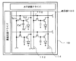
一方アクティマトリクス型表示装置に適用した場合、透明基板10の上に薄膜トランジスタを画素毎に形成し、絶縁層でこの薄膜トランジスタを覆い、絶縁層の上に、薄膜トランジスタに接続され画素毎に個別パターンに形成された透明な第1電極20、発光素子層30、半透明で各画素共通の第2電極22を順に積層し、この共通第2電極22の上に更に反射防止層46を形成した構成が採用可能である。図3は、このようなアクティブマトリクス型の有機EL表示装置の概略回路構成を示し、図4はこのような有機EL表示装置における1画素内での一部断面構造を示す。
【0038】
まず、透明基板10上には、複数の画素がマトリクス状に配列された表示部120が形成されており、各画素にはそれぞれ有機EL素子(EL)50と、この有機EL素子50での発光を画素毎に制御するためのスイッチ素子(ここでは薄膜トランジスタ:TFT)、及び表示データを保持する保持容量Cscが設けられている。
【0039】
図3の例では、各画素には第1及び第2薄膜トランジスタTr1,Tr2が形成され、第1トランジスタTr1は、走査ライン110に接続され、走査信号が印加されてオン制御されたとき、対応するデータライン112に印加されている表示内容に応じた電圧信号が第1薄膜トランジスタTr1を介して第2薄膜トランジスタTr2のゲートに印加され、また2つの薄膜トランジスタTr1,Tr2の間に接続された保持容量Cscによって一定期間保持される。そして、第2薄膜トランジスタTr2は、この保持容量Cscで保持されてゲートに印加される電圧に応じた電流を電源ライン114からこの第2薄膜トランジスタTr2に接続された有機EL素子の陽極(正孔注入電極)20に供給する。有機EL素子50は、この供給される電流量に応じた輝度で発光し、発光光は、第2電極22の背面側の反射防止層46で多少失われるものの大半が透明な第1電極20及び透明基板10を通過して外部に射出される。
【0040】
図4は、図3に示すようなアクティブマトリクス型有機EL表示装置の1画素における第2薄膜トランジスタTr2とこれに接続された有機EL素子50の概略断面構造を示している。図4に示す例では、第1薄膜トランジスタTr1は省略しているが、薄膜トランジスタTr2とほぼ同様の構造を備えており、薄膜トランジスタTr1、Tr2のいずれもその能動層120に、非晶質シリコンをレーザアニールにて多結晶化した多結晶シリコンを用いている。また本実施形態においてこの薄膜トランジスタTr1及びTr2は、能動層120を覆って形成されたゲート絶縁層130の上方にゲート電極132を備えるいわゆるトップゲート型TFTであり、能動層120のゲート電極132の下に位置する領域はチャネル領域120c、チャネル領域120cの両側には所定導電型の不純物がドープされたソース領域120s及びドレイン領域120dが形成されている。
【0041】
ゲート電極132を覆う基板のほぼ全面には層間絶縁層134が形成され、層間絶縁層134に開口されたコンタクトホールを介してソース領域120s、ドレイン領域120dの一方には電源ライン114が接続され、他方にはコネクタ電極136が接続されている。また、これら全てを覆うように無機材料又は有機材料からなる第1平坦化絶縁層(通常の層間絶縁膜でも良い)138が形成され、この平坦化絶縁層138の上に有機EL素子50の第1電極20が積層され、第1電極20の端部を覆うように第2平坦化絶縁層140が積層されている。なお、第1電極20は、第1平坦化絶縁層138に形成されたコンタクトホールにおいてコンタクト電極136と接続されている。第1電極20の上には、既に説明したとおり、発光素子層30、第2電極22及び反射防止層46がこの順に形成されている。
【0042】
以上のような構成において、表示装置の光取り出し側は透明基板10側であり、トップゲート型の上記第1及び第2薄膜トランジスタTr1、Tr2は、光が照射されるとリークの起きやすい多結晶シリコンからなる能動層120が光取り出し側に位置することになる。従って、外光の照射によるリーク電流発生を防止するため、図4に示すように、少なくとも第1及び第2薄膜トランジスタTr1,Tr2の基板10との間に、例えば能動層側からSiO2、SiNxの積層構造からなる絶縁層150を挟んで遮光層160を形成しておくことが好ましい。そして、この遮光層160は、図4の構成例では、最も光取り出し側に近い位置に形成され、また、通常遮光層は金属材料を用いて形成されるため、その表面反射率が高いと上述のようにコントラスト低下や、表示品質などに悪影響を及ぼす可能性がある。従って、背面側の反射防止層46と同様に、表面反射率の低い遮光性材料、例えば酸化クロムやモリブデンなどを用いて形成することがより好ましい。
【0043】
このように、薄膜トランジスタTr1、Tr2の形成領域であって光取り出し側に形成される遮光層160として光反射率の低い反射防止遮光層を形成し、また、背面側に形成される第2電極22を半透過性として反射率を下げ、更に第2電極22の背面側に反射率の低い反射防止層46を設けることにより、コントラストの非常に高い表示を可能とすると共に、高輝度で信頼性の高い有機EL表示装置を実現することができる。
【0044】
【発明の効果】
以上説明したように、本発明によれば、背面側の電極での外光反射を抑制することができ、コントラストの高い発光素子及びこの発光素子を用いた表示装置を実現することができる。
【図面の簡単な説明】
【図1】本発明の実施形態に係る有機EL素子の概略断面構造を示す図である。
【図2】本発明の実施形態に係る有機EL素子の半透過性の第2電極の構成例を示す図である。
【図3】本発明の実施形態に係るアクティブマトリクス型有機EL表示装置の概略回路構成を示す図である。
【図4】図3に示す表示装置に1画素内の一部断面を示す図である。
【符号の説明】
10 透明基板、20 第1電極(正孔注入電極)、22 第2電極(電子注入電極)、30 発光素子層、32 正孔注入層、34 正孔輸送層、36 発光層、38 電子輸送層、40 電子注入層、46 反射防止層、50 有機EL素子、100 表示部、110 走査ライン、112 データライン、114電源ライン、120 能動層、130 ゲート絶縁層、132 ゲート電極、134 層間絶縁層、136 コンタクト電極、138 第1平坦化絶縁層、140 第2平坦化絶縁層、150絶縁層、160 遮光層。[0001]
TECHNICAL FIELD OF THE INVENTION
The present invention relates to a structure of a light emitting element used for a display device or the like, and particularly to a structure on a back side thereof.
[0002]
[Prior art]
As a light-emitting element, recently, an electroluminescence (EL) element has attracted attention, and a display device using this EL element has been studied as an alternative to a display device such as a liquid crystal display device (LCD) or a CRT. Is underway.
[0003]
Of the EL elements, a so-called organic EL element using an organic compound as a light-emitting material has a structure in which a light-emitting element layer containing organic light-emitting molecules is interposed between a hole injection electrode (anode) and an electron injection electrode (cathode). . More specifically, a transparent conductive layer made of ITO (Indium Tin Oxide) is formed as a hole injection electrode on a transparent glass substrate, and a single-layer or multilayer light-emitting element layer is formed on the hole injection electrode. An opaque metal electrode such as Al, Ag, or MgAg is formed as an electron injection electrode on the light emitting element layer.
[0004]
In such a structure, holes injected from the hole injection electrode and electrons injected from the electron injection electrode are recombined in the light emitting element layer, and the organic light emitting molecules contained in the layer are excited. Light emitted when the molecule returns to the ground state passes through the transparent hole injection electrode and the glass substrate and is extracted to the outside.
[0005]
Here, since the metal electrode located on the back side with respect to the light emission side (observation side) is usually made of a highly reflective metal material, it passes through the substrate and the transparent electrode on the surface on the light emitting element side. As a result, reflection of external light entering the element occurs. This reflection of external light is a major cause of lowering the contrast, particularly in the case of black display in the display device. In addition, the surrounding image is reflected on the observation surface (reflection surface) of the metal electrode, and the visibility of the display image is improved. The display quality deteriorates, for example, the display quality decreases.
[0006]
As a simple method for preventing the deterioration of the display quality due to the reflection of the metal electrode, a polarizing layer used in an LCD may be formed on a transparent glass substrate or on the glass substrate side of a transparent hole injection electrode, that is, the observation surface of the element. The arrangement on the (light extraction surface) side is disclosed in, for example,
[0007]
[Patent Document 1]
JP-A-7-142170 [Problems to be Solved by the Invention]
As described in
[0008]
That is, light that has passed through the polarizing layer from the outside of the element and entered the element is linearly polarized light parallel to the polarization direction of the polarizing layer. When this linearly polarized light is reflected by the metal electrode, the polarization direction is reversed by 90 °. become. Therefore, the polarization direction of the light reflected by the metal electrode is different from the polarization direction of the polarizing layer, so that the light cannot pass through the polarizing layer and is blocked.
[0009]
By providing the polarizing layer in this way, it is possible to prevent reflected light from being emitted to the light extraction surface, and to suppress a decrease in contrast. However, since the polarizing layer exists on the light extraction side of the device, light from the light emitting layer cannot be extracted to the outside unless it passes through the polarizing layer. Since the polarizing plate transmits only light having a polarization direction parallel to the polarization direction of the polarizing layer among the light emitted from the light emitting layer, most of the emitted light cannot be passed through the polarizing layer and is absorbed. Therefore, the use efficiency of the emitted light is significantly reduced by providing the polarizing layer, and it is necessary to increase the emission luminance of the organic EL element in order to increase the amount of light actually extracted outside the element. The amount of current flowing between the hole injection electrode and the electron injection electrode (the light emitting element layer) must be increased.
[0010]
However, in the organic EL element, there is a problem that as the current flowing through the light-emitting element layer containing an organic compound such as a light-emitting molecule increases, the luminance reduction rate increases and the element life is shortened. On the other hand, a new organic light-emitting material capable of high-efficiency light emission is required to obtain high brightness without increasing the amount of current, and durability is required to realize a long-life element even when the amount of current is increased. We have to wait for the development of high-priced organic light-emitting materials.
[0011]
In order to solve the above-described problems, the present invention provides a light-emitting element and a light-emitting display device with high contrast, long life, and high luminance.
[0012]
[Means for Solving the Problems]
The present invention provides a light-emitting element including a light-emitting element layer between a first electrode and a second electrode, wherein one of the first electrode and the second electrode serves as a light-emitting side electrode and emits light to the outside. The rear electrode disposed on the rear side of the light-emitting side electrode is composed of a semi-transmissive electrode that partially transmits light incident from the light-emitting element layer side, and is reflected on the rear side of the semi-transmissive electrode. A prevention layer is provided.
[0013]
According to another aspect of the present invention, there is provided a light-emitting display device including a light-emitting element including a light-emitting element layer between a first electrode and a second electrode, wherein the first electrode is connected to the outside of the device. An electrode formed on a transparent substrate disposed on a light emitting side and capable of transmitting light emitted from the light emitting element layer, wherein the second electrode is interposed between the first electrode and the light emitting element layer. A semi-transmissive electrode formed on the back side of the first electrode so as to face and partially transmitting light incident from the light-emitting element layer side; and an anti-reflection layer provided on the back side of the second electrode. I have.
[0014]
In another aspect of the present invention, in a display device including an electroluminescent element including a light emitting element layer between an anode and a cathode, the anode is formed on a transparent substrate that is a light emission side to the outside, An electrode capable of transmitting light emitted from the light emitting element layer, the cathode is formed on the back side of the anode so as to face the anode with the light emitting element layer interposed therebetween, and is emitted from the light emitting element layer. And a semi-transmissive electrode capable of partially transmitting light, and an anti-reflection layer is formed on the back side of the cathode.
[0015]
As described above, by adopting a semi-transparent electrode as a back electrode located on the back side with respect to the light emission side electrode of the light emitting element, a low reflection layer or an anti-reflection layer is provided on the back side of the back electrode. In addition, external light incident on the element can be transmitted without being reflected on the surface of the back electrode, and can be absorbed by the antireflection layer having a low reflectance. Light that travels from the light-emitting element layer to the transparent light-emitting side electrode can pass through the light-emitting side electrode and through the transparent substrate, and efficiently emit light out of the element with minimal loss. Can be. Therefore, of the light emitted from the light emitting element layer, the light that has proceeded to the back electrode side is not reflected like the external light but is absorbed by the antireflection layer, but the contrast can be prevented from lowering due to the reflection of the external light, The display quality can be improved by improving the contrast more than the loss of the light that has proceeded to the back electrode side. For example, a light-emitting element that is easy to see and can be visually recognized and has high actual luminance can be realized.
[0016]
In another aspect of the present invention, in the light-emitting element or the display device, the semi-transmissive electrode includes a metal layer thinned to allow light to pass therethrough, or a mesh-like metal layer having an opening through which light passes. Used.
[0017]
According to another aspect of the present invention, in the light emitting element or the display device, an Ag layer or a MgAg layer having a thickness of 20 nm or less is used for the transflective electrode.
[0018]
By making the metal layer thin or having a configuration in which an opening is provided in this way, light can be transmitted and the electrode material itself can be adopted without being changed, and a function required as an electrode can be exhibited. it can.
[0019]
In another aspect of the present invention, in the light emitting element or the display device, molybdenum or chromium oxide is used for the low reflection layer or the antireflection layer.
[0020]
By adopting molybdenum and chromium oxide for the anti-reflection layer, a layer with low light reflectance on the surface can be easily formed on the back side of the back side electrode, and external light transmitted through the semi-transparent back electrode is reflected. Thus, it is possible to prevent the light from being emitted again from the element.
[0021]
BEST MODE FOR CARRYING OUT THE INVENTION
Hereinafter, preferred embodiments of the present invention (hereinafter, embodiments) will be described with reference to the drawings.
[0022]
Examples of the light emitting element according to the embodiment of the present invention include an EL element. FIG. 1 shows a schematic cross-sectional structure of an element according to an embodiment of the present invention, taking an EL element as an example. As the
[0023]
The
[0024]
Various structures can be adopted for the light emitting
[0025]
The light emitting layer 36 is made of an appropriate material in order to obtain R, B, and G light.
[0026]
In the case where the light-emitting
[0027]
In the example of FIG. 1, the second electrode 22 functions as a cathode, and is required to have a function of efficiently injecting electrons into the light emitting
[0028]
Therefore, in the present embodiment, first, when an appropriate Al, Ag, AgMg layer is used as an electron injection material for the second electrode 22, for example, the thickness of the second electrode 22 is reduced to about 5 nm to about 40 nm to achieve light transmission. Property can be ensured. For example, by forming a thin film having a thickness of about 20 nm, a light transmittance of 50% or more, that is, a semi-transmissive electrode is realized without impairing the electron injection function. A metal material such as Al can be formed by, for example, a vacuum evaporation method or the like in the same manner as the respective layers of the light emitting
[0029]
As another method for using a light-shielding metal material such as Al as the material of the second electrode 22 and realizing semi-transparency, as shown in FIG. For example, a mesh shape (including a grid shape) having an opening through which light can pass in a unit display area may be used. Each opening has any shape, such as a circle or a polygon. However, when a metal layer is formed and then selectively etched and removed by photolithography or the like, there is little etching residue and an opening in a unit region. It is preferable that the areas are equal as much as possible from the viewpoint of preventing a variation in display quality.
[0030]
The semi-transmissive second electrode 22 is not limited to the above-described metal material, and may be any material that is conductive and has a small work function with sufficient light transmittance without being thinned. .
[0031]
In the present embodiment, the anti-reflection layer 46 is formed as described above so as to cover the second electrode 22 having such a semi-transmission function, and the light transmitted through the second electrode 22 is absorbed by the anti-reflection light 46 and reflected. To prevent Any of chromium oxide and molybdenum that can be used as the material of the anti-reflection layer 46 can be easily formed by forming the second electrode 22 by vacuum evaporation, changing the evaporation source to an anti-reflection material, and performing continuous evaporation. It can be formed by lamination. Here, when molybdenum is used as the material of the anti-reflection layer 46, the reflectance of the anti-reflection layer 46 can be about 20% or less, and when chromium oxide is used, it is about 5% or less. Can be.
[0032]
Here, the degree of reflectance of the material to be selected as the anti-reflection layer 46 is determined in consideration of required luminance, luminous luminance and luminous efficiency of luminous molecules in the
[0033]
Here, the material of the antireflection layer 46 is not necessarily limited to the material containing a metal element as described above, but the reflection using molybdenum, chromium oxide, or the like is provided on the back side of the semi-transmissive second electrode 22. By providing the prevention layer 46, not only the reflection of external light can be prevented but also a heat dissipation function can be exhibited. That is, a molybdenum layer or a chromium oxide layer has a relatively high thermal conductivity, and prevents heat generated in the light emitting
[0034]
When a polarizing layer is provided on the observation side of the element, for example, between the first electrode and the glass substrate or on the surface of the glass substrate as in
[0035]
The structure of the organic EL element including the antireflection layer as an example of the light emitting element according to the embodiment described above can be applied to a flat light emitting display device or the like employing this element for each display pixel. In the flat display device, an active matrix type display device having a switch element for driving each display element in each pixel and a simple matrix type display device having a simple structure without such a switch element are known. The organic EL element of the embodiment can be applied to any type of display device.
[0036]
When applied to a simple matrix display device, as shown in FIG. 1, a transparent (but may be translucent)
[0037]
On the other hand, when applied to an active matrix type display device, a thin film transistor is formed for each pixel on the
[0038]
First, a
[0039]
In the example of FIG. 3, first and second thin film transistors Tr1 and Tr2 are formed in each pixel, and the first transistor Tr1 is connected to the
[0040]
FIG. 4 shows a schematic sectional structure of the second thin film transistor Tr2 and the
[0041]
An interlayer insulating layer 134 is formed on substantially the entire surface of the substrate covering the gate electrode 132, and a
[0042]
In the above configuration, the light extraction side of the display device is on the
[0043]
As described above, an anti-reflection light-shielding layer having a low light reflectance is formed as the light-
[0044]
【The invention's effect】
As described above, according to the present invention, it is possible to suppress the reflection of external light on the rear electrode, and to realize a light emitting element with high contrast and a display device using the light emitting element.
[Brief description of the drawings]
FIG. 1 is a view showing a schematic sectional structure of an organic EL device according to an embodiment of the present invention.
FIG. 2 is a diagram showing a configuration example of a semi-permeable second electrode of the organic EL element according to the embodiment of the present invention.
FIG. 3 is a diagram showing a schematic circuit configuration of an active matrix organic EL display device according to an embodiment of the present invention.
4 is a diagram showing a partial cross section of one pixel in the display device shown in FIG.
[Explanation of symbols]
DESCRIPTION OF
Claims (6)
前記第1電極と前記第2電極の内、
一方は光射出側電極として、外部への光射出側に配置され、
該光射出側電極の背面側に位置する背面側電極は、発光素子層側から入射する光を一部透過する半透過電極より構成され、
該半透過電極の背面側に反射防止層が設けられていることを特徴とする発光素子。In a light-emitting element including a light-emitting element layer between a first electrode and a second electrode,
Among the first electrode and the second electrode,
One is disposed on the light emission side to the outside as a light emission side electrode,
The back side electrode located on the back side of the light emitting side electrode is configured by a semi-transmissive electrode that partially transmits light incident from the light emitting element layer side,
A light-emitting device, wherein an anti-reflection layer is provided on the back side of the transflective electrode.
前記第1電極は、装置の外部への光射出側に配置される透明基板の上に形成され、前記発光素子層から射出される光を透過可能な電極であり、
前記第2電極は、前記発光素子層を挟んで前記第1電極と対向するように該第1電極の背面側に形成され、前記発光素子層側から入射する光を一部透過する半透過電極であり、
前記第2電極の背面側に反射防止層が設けられていることを特徴とする発光表示装置。A light-emitting display device including a light-emitting element including a light-emitting element layer between a first electrode and a second electrode,
The first electrode is formed on a transparent substrate disposed on a light emission side to the outside of the device, and is an electrode capable of transmitting light emitted from the light emitting element layer,
The second electrode is formed on the back side of the first electrode so as to face the first electrode with the light emitting element layer interposed therebetween, and is a semi-transmissive electrode that partially transmits light incident from the light emitting element layer side. And
A light-emitting display device, wherein an anti-reflection layer is provided on the back side of the second electrode.
前記陽極は、外部への光射出側となる透明基板の上に形成され、前記発光素子層から射出される光を透過可能な電極を備え、
前記陰極は、前記発光素子層を挟んで前記陽極と対向するように該陽極の背面側に形成され、前記発光素子層から射出される光を一部透過可能な半透過電極を備え、
前記陰極の背面側には反射防止層が形成されていることを特徴とする表示装置。In a display device including an electroluminescent element including a light emitting element layer between the anode and the cathode,
The anode is formed on a transparent substrate on the light emission side to the outside, and includes an electrode capable of transmitting light emitted from the light emitting element layer,
The cathode is formed on the back side of the anode so as to face the anode with the light emitting element layer interposed therebetween, and includes a semi-transmissive electrode capable of partially transmitting light emitted from the light emitting element layer,
A display device, wherein an anti-reflection layer is formed on the back side of the cathode.
前記半透過電極には、光を透過可能に薄膜化されている金属層、又は光を通過させる開口を備えた網目状金属層が用いられていることを特徴とする発光素子又は表示装置。The light emitting device or the display device according to any one of claims 1 to 3,
A light emitting element or a display device, wherein the semi-transmissive electrode includes a metal layer thinned to allow light to pass therethrough or a mesh-like metal layer having an opening through which light passes.
前記半透過電極には、20nm以下の厚さのAg層又はMgAg層が用いられていることを特徴とする発光素子又は表示装置。The light emitting device or the display device according to any one of claims 1 to 3,
A light emitting element or a display device, wherein an Ag layer or a MgAg layer having a thickness of 20 nm or less is used for the transflective electrode.
前記反射防止層には、モリブデン又は酸化クロムが用いられていることを特徴とする発光素子又は表示装置。The light-emitting element or the display device according to any one of claims 1 to 5,
A light-emitting element or a display device, wherein molybdenum or chromium oxide is used for the antireflection layer.
Priority Applications (5)
| Application Number | Priority Date | Filing Date | Title |
|---|---|---|---|
| JP2003092535A JP2004303481A (en) | 2003-03-28 | 2003-03-28 | Light-emitting element and emission display device |
| TW093105490A TWI247555B (en) | 2003-03-28 | 2004-03-03 | Light emitting element and display device |
| US10/807,656 US20040206960A1 (en) | 2003-03-28 | 2004-03-24 | Light emitting element and light emitting display |
| KR1020040020656A KR100584068B1 (en) | 2003-03-28 | 2004-03-26 | Light-emitting element, display device and light-emitting display device |
| CNA2004100316087A CN1535096A (en) | 2003-03-28 | 2004-03-29 | Lighting assembly and lighting display device |
Applications Claiming Priority (1)
| Application Number | Priority Date | Filing Date | Title |
|---|---|---|---|
| JP2003092535A JP2004303481A (en) | 2003-03-28 | 2003-03-28 | Light-emitting element and emission display device |
Publications (2)
| Publication Number | Publication Date |
|---|---|
| JP2004303481A true JP2004303481A (en) | 2004-10-28 |
| JP2004303481A5 JP2004303481A5 (en) | 2006-04-20 |
Family
ID=33156630
Family Applications (1)
| Application Number | Title | Priority Date | Filing Date |
|---|---|---|---|
| JP2003092535A Pending JP2004303481A (en) | 2003-03-28 | 2003-03-28 | Light-emitting element and emission display device |
Country Status (5)
| Country | Link |
|---|---|
| US (1) | US20040206960A1 (en) |
| JP (1) | JP2004303481A (en) |
| KR (1) | KR100584068B1 (en) |
| CN (1) | CN1535096A (en) |
| TW (1) | TWI247555B (en) |
Cited By (5)
| Publication number | Priority date | Publication date | Assignee | Title |
|---|---|---|---|---|
| JP2009230960A (en) * | 2008-03-21 | 2009-10-08 | Toshiba Corp | Display device and illumination device using organic electroluminescent element |
| US8039120B2 (en) | 2005-03-07 | 2011-10-18 | Samsung Mobile Display Co., Ltd. | Organic electroluminescence device and method of manufacturing the same |
| KR101156436B1 (en) | 2010-01-19 | 2012-06-18 | 삼성모바일디스플레이주식회사 | Optical film and organic light emitting display apparatus having the same |
| JP2013224976A (en) * | 2012-04-19 | 2013-10-31 | Toshiba Corp | Display device |
| KR20190132378A (en) | 2017-03-29 | 2019-11-27 | 지오마텍 가부시키가이샤 | Electrode for organic electroluminescence element, organic electroluminescence element, organic electroluminescence display device, and method for manufacturing electrode for organic electroluminescence element |
Families Citing this family (28)
| Publication number | Priority date | Publication date | Assignee | Title |
|---|---|---|---|---|
| JP2004355813A (en) * | 2003-05-27 | 2004-12-16 | Tohoku Pioneer Corp | Self-luminous display equipment and information equipment using the same |
| KR100704258B1 (en) * | 2004-06-02 | 2007-04-06 | 세이코 엡슨 가부시키가이샤 | Organic el device and electronic apparatus |
| TWI266129B (en) * | 2004-11-30 | 2006-11-11 | Sanyo Electric Co | Lighting device and reflection type liquid crystal display device using the same |
| TWI341948B (en) * | 2005-05-20 | 2011-05-11 | Epson Imaging Devices Corp | Display device |
| TW200641465A (en) * | 2005-05-20 | 2006-12-01 | Sanyo Epson Imaging Devices Co | Display device |
| US7429753B2 (en) * | 2005-05-20 | 2008-09-30 | Sanyo Electric Co., Ltd. | Display device |
| TWI340607B (en) | 2005-08-12 | 2011-04-11 | Au Optronics Corp | Organic electroluminescent display panel and fabricating method thereof |
| CN1753586B (en) * | 2005-08-26 | 2011-08-24 | 友达光电股份有限公司 | Organic electroluminescence display device manufacturing method |
| JP2009133914A (en) * | 2007-11-28 | 2009-06-18 | Sony Corp | Display apparatus |
| KR101545315B1 (en) * | 2008-09-17 | 2015-08-20 | 삼성디스플레이 주식회사 | Organic light emitting diode display |
| JP4930501B2 (en) | 2008-12-22 | 2012-05-16 | ソニー株式会社 | Display device and electronic device |
| KR101125570B1 (en) | 2009-12-04 | 2012-03-22 | 삼성모바일디스플레이주식회사 | Organic light emitting diode device |
| KR101714539B1 (en) * | 2010-08-24 | 2017-03-23 | 삼성디스플레이 주식회사 | Organic light emitting display device |
| KR101804360B1 (en) * | 2011-03-21 | 2017-12-05 | 삼성디스플레이 주식회사 | Organic light emitting display apparatus |
| CN104183749A (en) * | 2013-05-22 | 2014-12-03 | 海洋王照明科技股份有限公司 | Inversed organic light emission diode, display screen and terminal |
| CN103474450A (en) * | 2013-09-11 | 2013-12-25 | 京东方科技集团股份有限公司 | Display panel and manufacturing method thereof and display device |
| KR102207914B1 (en) * | 2014-10-10 | 2021-01-27 | 삼성디스플레이 주식회사 | Organic light emitting display device |
| KR102495112B1 (en) | 2015-03-26 | 2023-02-03 | 삼성디스플레이 주식회사 | Organic light emitting display apparatus and manufacturing method thereof |
| CN208488734U (en) | 2015-08-21 | 2019-02-12 | 3M创新有限公司 | Transparent conductor including metal trace |
| WO2017043242A1 (en) | 2015-09-10 | 2017-03-16 | シャープ株式会社 | Organic electroluminescence device, lighting device and display device |
| US9680132B1 (en) * | 2015-11-30 | 2017-06-13 | Industrial Technology Research Institute | Display device and optical film |
| KR20170085157A (en) * | 2016-01-13 | 2017-07-24 | 삼성디스플레이 주식회사 | Organic light emitting display device |
| CN106067514A (en) * | 2016-08-11 | 2016-11-02 | 华南理工大学 | A kind of translucent organic solar batteries and preparation method thereof |
| JP2018067371A (en) * | 2016-10-17 | 2018-04-26 | 株式会社Joled | Display device and electronic apparatus |
| JP6884849B2 (en) * | 2017-03-03 | 2021-06-09 | 日本化薬株式会社 | Image display device |
| CN110767660B (en) * | 2018-07-24 | 2022-09-16 | 京东方科技集团股份有限公司 | Array substrate, preparation method thereof and display panel |
| WO2021102664A1 (en) * | 2019-11-26 | 2021-06-03 | 重庆康佳光电技术研究院有限公司 | Display assembly and electronic device using display assembly |
| CN112768618B (en) * | 2021-01-07 | 2023-01-24 | 苏州清越光电科技股份有限公司 | Display panel, preparation method thereof and display device |
Family Cites Families (4)
| Publication number | Priority date | Publication date | Assignee | Title |
|---|---|---|---|---|
| JP2000040591A (en) * | 1998-07-21 | 2000-02-08 | Sony Corp | Organic electroluminescence element |
| US6291839B1 (en) * | 1998-09-11 | 2001-09-18 | Lulileds Lighting, U.S. Llc | Light emitting device having a finely-patterned reflective contact |
| KR100491143B1 (en) * | 2001-12-26 | 2005-05-24 | 삼성에스디아이 주식회사 | Flat Panel Display with Black Matrix and Method for fabricating the Same |
| JP3972670B2 (en) * | 2002-02-06 | 2007-09-05 | 豊田合成株式会社 | Light emitting device |
-
2003
- 2003-03-28 JP JP2003092535A patent/JP2004303481A/en active Pending
-
2004
- 2004-03-03 TW TW093105490A patent/TWI247555B/en active
- 2004-03-24 US US10/807,656 patent/US20040206960A1/en not_active Abandoned
- 2004-03-26 KR KR1020040020656A patent/KR100584068B1/en active IP Right Grant
- 2004-03-29 CN CNA2004100316087A patent/CN1535096A/en active Pending
Cited By (7)
| Publication number | Priority date | Publication date | Assignee | Title |
|---|---|---|---|---|
| US8039120B2 (en) | 2005-03-07 | 2011-10-18 | Samsung Mobile Display Co., Ltd. | Organic electroluminescence device and method of manufacturing the same |
| JP2009230960A (en) * | 2008-03-21 | 2009-10-08 | Toshiba Corp | Display device and illumination device using organic electroluminescent element |
| KR101156436B1 (en) | 2010-01-19 | 2012-06-18 | 삼성모바일디스플레이주식회사 | Optical film and organic light emitting display apparatus having the same |
| US8550667B2 (en) | 2010-01-19 | 2013-10-08 | Samsung Display Co., Ltd. | Optical film and organic light emitting display apparatus including the same |
| JP2013224976A (en) * | 2012-04-19 | 2013-10-31 | Toshiba Corp | Display device |
| US8987712B2 (en) | 2012-04-19 | 2015-03-24 | Kabushiki Kaisha Toshiba | Display device |
| KR20190132378A (en) | 2017-03-29 | 2019-11-27 | 지오마텍 가부시키가이샤 | Electrode for organic electroluminescence element, organic electroluminescence element, organic electroluminescence display device, and method for manufacturing electrode for organic electroluminescence element |
Also Published As
| Publication number | Publication date |
|---|---|
| KR20040085010A (en) | 2004-10-07 |
| TW200423807A (en) | 2004-11-01 |
| CN1535096A (en) | 2004-10-06 |
| KR100584068B1 (en) | 2006-05-29 |
| TWI247555B (en) | 2006-01-11 |
| US20040206960A1 (en) | 2004-10-21 |
Similar Documents
| Publication | Publication Date | Title |
|---|---|---|
| KR100584068B1 (en) | Light-emitting element, display device and light-emitting display device | |
| KR100989134B1 (en) | Organic light emitting diode display and method of manufacturing the same | |
| KR100949339B1 (en) | Both-sides emission type organic light emitting diode display | |
| KR101002663B1 (en) | Organic light emitting diode display | |
| KR101826849B1 (en) | Organic light emitting diode display | |
| EP2216840B1 (en) | Organic light emitting diode display | |
| KR100959107B1 (en) | Organic light emitting diode display | |
| KR100959108B1 (en) | Organic light emitting diode display | |
| KR101002662B1 (en) | Organic light emitting diode display and method of manufacturing the same | |
| KR102148857B1 (en) | Display device and method for manufacturing the same | |
| KR20140106868A (en) | Organic light emitting display and manufactucring method of the same | |
| KR20100081772A (en) | Organic light emitting diode display | |
| JP4637831B2 (en) | ORGANIC ELECTROLUMINESCENCE ELEMENT, ITS MANUFACTURING METHOD, AND DISPLAY DEVICE | |
| JP2011119223A (en) | Organic light-emitting display device | |
| KR20150009126A (en) | Organic light emitting diode display and method for manufacturing the same | |
| JP2004070351A (en) | Electroluminescence display device | |
| KR101084239B1 (en) | Organic light emitting diode display | |
| KR101432236B1 (en) | Organic light emitting diode display | |
| KR100965250B1 (en) | Organic light emitting diode display | |
| KR101708421B1 (en) | Organic light emitting diode display | |
| KR20190077673A (en) | Organic light emitting display device | |
| KR100611758B1 (en) | OLED, OLED panel and fabricating method of the same | |
| JP5117553B2 (en) | Manufacturing method of display device | |
| KR20200066599A (en) | Organic light emitting display device and manufacturing method thereof | |
| CN116367624A (en) | Display apparatus |
Legal Events
| Date | Code | Title | Description |
|---|---|---|---|
| A521 | Request for written amendment filed |
Free format text: JAPANESE INTERMEDIATE CODE: A523 Effective date: 20060303 |
|
| A621 | Written request for application examination |
Free format text: JAPANESE INTERMEDIATE CODE: A621 Effective date: 20060303 |
|
| A977 | Report on retrieval |
Free format text: JAPANESE INTERMEDIATE CODE: A971007 Effective date: 20081217 |
|
| A131 | Notification of reasons for refusal |
Free format text: JAPANESE INTERMEDIATE CODE: A131 Effective date: 20090106 |
|
| A02 | Decision of refusal |
Free format text: JAPANESE INTERMEDIATE CODE: A02 Effective date: 20090512 |