JP2004291663A - System and method for monitoring vehicle periphery - Google Patents
System and method for monitoring vehicle periphery Download PDFInfo
- Publication number
- JP2004291663A JP2004291663A JP2003082651A JP2003082651A JP2004291663A JP 2004291663 A JP2004291663 A JP 2004291663A JP 2003082651 A JP2003082651 A JP 2003082651A JP 2003082651 A JP2003082651 A JP 2003082651A JP 2004291663 A JP2004291663 A JP 2004291663A
- Authority
- JP
- Japan
- Prior art keywords
- vehicle
- angle
- imaging
- imaging device
- display
- Prior art date
- Legal status (The legal status is an assumption and is not a legal conclusion. Google has not performed a legal analysis and makes no representation as to the accuracy of the status listed.)
- Granted
Links
- 238000012544 monitoring process Methods 0.000 title claims abstract description 47
- 238000000034 method Methods 0.000 title claims description 18
- 238000003384 imaging method Methods 0.000 claims description 66
- 230000008859 change Effects 0.000 claims description 18
- 230000002093 peripheral effect Effects 0.000 abstract 1
- 230000007246 mechanism Effects 0.000 description 11
- 238000012545 processing Methods 0.000 description 8
- 230000008569 process Effects 0.000 description 6
- 230000005540 biological transmission Effects 0.000 description 4
- 230000000694 effects Effects 0.000 description 3
- 238000012790 confirmation Methods 0.000 description 2
- 238000010586 diagram Methods 0.000 description 2
- 230000004044 response Effects 0.000 description 2
- 238000006243 chemical reaction Methods 0.000 description 1
- 238000001514 detection method Methods 0.000 description 1
- 238000004020 luminiscence type Methods 0.000 description 1
- 238000012986 modification Methods 0.000 description 1
- 230000004048 modification Effects 0.000 description 1
Images


Landscapes
- Fittings On The Vehicle Exterior For Carrying Loads, And Devices For Holding Or Mounting Articles (AREA)
- Closed-Circuit Television Systems (AREA)
Abstract
Description
【0001】
【発明の属する技術分野】
本発明は、車両の周辺を撮像して、車室内に設置された表示装置に表示させることで監視を行なうための車両周辺監視システム、及び車両周辺監視方法に関する。
【0002】
【従来の技術】
車両周辺監視システムは、例えば後方などの車両の周辺をカメラで撮像し、その映像を車室内のディスプレイに表示させて運転者が監視を行うために使用される。例えば、特許文献1には、1台のカメラを共用し、至近視界を確保すると共に車両距離の検出精度も確保することを目的として、スイッチを操作することでカメラの画角を広角と狭角とに切り替える構成が開示されている。また、特許文献2には、車両の走行速度や走行方向に応じて適切な監視が行なえるように、カメラの向きを右前方、右後方に切替える構成が開示されている。
【0003】
【特許文献1】
特開平8−301010号公報
【0004】
【特許文献2】
特開平9−295539号公報
【0005】
【発明が解決しようとする課題】
これらの従来技術は、夫々において技術的課題として認識したものを解決するために成されている。例えば、車両の周辺監視における比較的重要なポイントとして、以下の2点がある。
▲1▼低速走行時において、車両の陰になり極めて視認し難くなる車両の後方側極近傍の領域を監視する。
▲2▼高速走行時において、後続車両の状況を、バックミラーなどから得られる情報よりも広範囲で得る。
【0006】
そして、これら▲1▼,▲2▼のポイントを同時にクリアするには、夫々の用途に応じて複数のカメラを配置すれば可能であるが、コストの問題から1台のカメラによることを前提とすると、極めて困難となる。
【0007】
例えば、先ず、▲2▼を満たすことを優先してカメラを略水平に配置しておいた場合、▲1▼を満たすためにカメラの画角を広角に切替えることが考えられる。しかし、その場合、1台のカメラでは、広角表示の一部分でしか極近傍領域を捉えることができない。そして、上記の従来技術では、何れも斯様な問題を解決することは目的とされていない。即ち、特許文献2に開示されているようにカメラの向きを切替えたとしても、上記▲1▼,▲2▼のポイントを同時に満たすことは不可能である。
【0008】
また、特許文献2のようにカメラの向きを切替えるようにすると、運転者は、現在ディスプレイで見ている画像がどのような方向で撮像されたものかを把握し難くなってしまう場合があり、周辺状況の適切な把握が困難になるという問題がある。
【0009】
本発明は上記事情に鑑みてなされたものであり、その第1の目的は、1つの撮像装置によって車両周辺の状況をより多様な形態で監視することができる車両周辺監視システムを提供することにある。
【0010】
また、本発明の第2の目的は、撮像装置による撮像方向が変化した場合に、その変化を車両の乗員が認識し易くなる車両周辺監視システムを提供することにある。
【0011】
【課題を解決するための手段】
請求項1記載の車両周辺監視システムによれば、制御手段は、撮像装置による撮像中心角度を、車両の低速走行時には俯角方向に設定し、車両の高速走行時には略水平方向に設定する。即ち、前者の場合は、低速走行時において車両の陰になり、極めて視認し難くなる車両の後方側極近傍の領域を監視することができる。そして、後者の場合は、高速走行時において後続車両の状況を、バックミラーなどから得られる情報よりも広範囲で得ることができる。従って、車両を運転する場合に安全を確保するため極めて重要な2つの監視態様を、1台の撮像装置を用いて実現することが可能となる。
【0012】
請求項2記載の車両周辺監視システムによれば、制御手段は、撮像装置による撮像中心角度を、車両の後進時にも俯角方向に設定するので、後進時においても安全確認が重要となる車両の後方側極近傍の領域を監視することができる。
【0013】
請求項3記載の車両周辺監視システムによれば、制御手段は、撮像装置による撮像中心角度を変化させることに応じて、表示装置における表示面の角度を変化させる。即ち、撮像装置の角度変化に連動させて表示装置における表示面角度を変化させることで、車両の乗員は、その表示面角度の変化によって撮像装置の撮像中心角度がどのような位置にあるのかを感覚的に把握することができる。従って、表示装置に表示されている画像が、車両の周辺をどのような方向から捉えたものであるのかが容易に判るようになり、監視を容易に行うことができる。
【0014】
請求項4記載の車両周辺監視システムによれば、制御手段は、車両側より与えられる車両情報に基づいて撮像装置による撮像中心角度を変化させると共に、その変化に応じて表示装置における表示面の角度を変化させるので、請求項3と略同様の作用効果を得ることができる。
【0015】
請求項5記載の車両周辺監視システムによれば、制御手段は、撮像装置による撮像中心角度を、車両の低速走行時には俯角方向に設定し、車両の高速走行時には略水平方向に設定するので、請求項4の構成において、請求項1と同様の作用効果を得ることができる。
【0016】
請求項6記載の車両周辺監視システムによれば、制御手段は、撮像装置による撮像中心角度を、車両の後進時にも俯角方向に設定するので、請求項5の構成において、請求項2と同様の作用効果を得ることができる。
【0017】
請求項7記載の車両周辺監視システムによれば、制御手段は、表示装置の表示面に対する運転者の視線方向角度と、表示面に対する撮像装置の撮像方向角度とが対称関係で等しくなるように表示面の角度を調整する。このように調整を行なうと、運転者が表示装置の表示面を見る方向に対して鏡像が形成される方向に、撮像装置の撮像方向角度が向いていることになる(ミラー対称)。従って、運転者は、表示装置に表示されている画像が、車両の周辺をどのような方向から捉えたものであるのかを、その時の表示面角度によって一層容易に把握することが可能となる。
【0018】
請求項8記載の車両周辺監視システムによれば、表示装置を広視野角ディスプレイで構成するので、表示面の角度を変化させた場合でも、車両の乗員は表示されている画像を確実に見ることができる。
【0019】
請求項9記載の車両周辺監視システムによれば、制御手段は、車両情報の変化に応じて撮像装置による撮像中心角度を略連続的に変化させるので、表示装置に表示される画像の状態が突然切替わることが無く、車両の乗員にとって、撮像方向の変化を把握し易くすることができる。
【0020】
請求項10記載の車両周辺監視システムによれば、撮像装置を車両の左前方角部に配置する。例えば、右ハンドルの国産車で、特に所謂RV車のように車高が高い車両の場合、車両の左側前方から後方にかけての視界が極めて得難くなってしまう。従って、撮像装置を車両の左前方角部に配置すれば、上記のような形態の車両において得難い視界を良好に確保することができる。
【0021】
【発明の実施の形態】
(第1実施例)
以下、本発明の第1実施例について図1乃至図5を参照して説明する。車両周辺監視システム全体の構成を示す図1において、車両1の後方側には、後方側の撮像を行なうためにCCD(Charge Coupled Device)などで構成されるカメラ(撮像装置)2が配置されている。そのカメラ2は、モータなどのアクチュエータを備えて構成されるにカメラ角度調整機構3より、撮像方向が鉛直方向において変更可能となるように構成されている。
【0022】
カメラ2によって撮像された画像信号は、システムコントローラ4を介して変換され、例えば自発光する素子であるEL(Electronic Luminescence)素子を画素として構成されるディスプレイ(表示装置)5に出力される。ディスプレイ5は、車室内部のインストルメントパネル上に配置されている。このディスプレイ5も、モータなどのアクチュエータを備えて構成されるディスプレイ角度調整機構6によって表示面の角度が鉛直方向において変更可能となるように構成されている。また、ディスプレイ5には、周辺監視システムを動作させるためのスイッチ5Sが設けられている。
そして、システムコントローラ4は、車両1側において各種の車両情報を収集すると共に、その情報に基づいて各種の制御を行うECU(Electronic Control Unit)20より送信される車両情報に基づいて、カメラ角度調整機構3とディスプレイ角度調整機構6に対して制御信号を出力することでカメラ2,ディスプレイ5夫々の角度調整を行なうようになっている。
【0023】
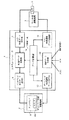
図2は、システムコントローラ4の内部構成を示す機能ブロック図である。システムコントローラ4はマイクロコンピュータで構成されており、図2に示す各機能ブロックはマイコンのハードウエア及びソフトウエアによって実現されるものである。システムコントローラ4は、カメラ2より送信されたNTSC形式のデータをカメラ映像データ受信部7で受信すると、映像データ変換部8によりアナログRGB信号に変換する。そして、変換した信号を、ディスプレイ表示データ送信部9を介してディスプレイ5に出力する。
【0024】
また、システムコントローラ4は、ECU20より送信される車両情報として、ACC信号(ON/OFF)、車両1の走行が前進/後進の何れであるかを示すF/R信号、及び車両速度Vを車両データ受信部10を介して受信して、データ計算部(制御手段)11に出力する。
【0025】
データ計算部11は、車両情報に基づいてカメラ2の角度やディスプレイ5の設定角度を求めると、カメラ,ディスプレイ角度調整データ送信部12,13を介してカメラ,ディスプレイ角度調整機構3,6に角度調整信号を出力するようになっている。また、データ計算部11は、映像データ変換部8に対しても例えばズームアップ、ズームダウンなどを制御するための信号を出力する。
【0026】
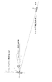
図3及び図4は、カメラ2とディスプレイ5との初期状態での配置関係を示す側面図及び平面図である。図3において、カメラ2は、鉛直面内において俯角方向にθcv(例えば30度)の角度で傾けられ、当初は車両の近傍を撮像するように調整されている。また、ディスプレイ5の表示中心を基準とする基準線(水平)に対して、車両1の運転席に着いた運転者の標準的な視点位置は、仰角方向にθuv(例えば20度)にあるものとする。この場合、ディスプレイ5の表示面の角度θdvは(1)式で設定される。
θdv=(θcv+θuv)/2=25(度) ・・・(1)
【0027】
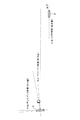
また、カメラ2とディスプレイ5は水平方向については変位せず、図4に示す初期状態のままとなる。即ち、カメラ2は車両1の真後ろを向く状態で固定されている(θch=0度)。そして、ディスプレイ5の表示中心を基準とする基準線に対して、車両1の運転席に着いた運転者の標準的な視点位置は、左方向(図4中の上方向)にθuh(例えば30度)にあるものとする。この場合、ディスプレイ5の表示面の角度θdhは、(2)式で設定される。
θdh=(θch+θuh)/2=15(度) ・・・(2)
【0028】
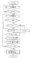
次に、本実施例の作用について図5も参照して説明する。図5は、システムコントローラ4の主にデータ計算部11による処理内容を示すフローチャートである。データ計算部11は、ディスプレイ5に配置されているスイッチ5SがONされると処理を開始する(スタート)。そして、車両データ受信部10を介して車両情報を例えば100ms毎に受信し(ステップS1)、ACC信号がONになると(ステップS2,「YES」)ステップS3に移行して、システム制御を行うために車両情報を受信する。
【0029】
尚、図5のフローチャートには図示しないが、ディスプレイ表示データ送信部9は、図5の処理に並行して、映像データ変換部8によって変換されたデータを一定周期(例えば周波数60Hz)でディスプレイ5に送信するようになっている。
【0030】
データ計算部11は、続くステップS4において車両情報を受信し、F/R信号により車両1の走行方向が後進であるか否かを判断する。そして、後進であれば(「YES」)ステップS6に移行し、後進でなければ(「NO」)ステップS5に移行して、車両速度Vがしきい値VS(例えば20km/h)以下であるか否かを判断する。
【0031】
ステップS5において、車両速度Vがしきい値VS以下であれば(「YES」)、データ計算部11はカメラ角度θcvを30度に設定し(ステップS6)、しきい値VSを超えていれば(「NO」)カメラ角度θcvを0度に設定する(ステップS7)。そして、何れの場合も、データ計算部11はカメラ角度調整データ送信部12を介してカメラ角度調整機構3に角度調整信号を送信する(ステップS8)。すると、カメラ角度調整機構3の作用によって、カメラ2の撮像中心角度は、鉛直面内において俯角方向に30度、又は0度(水平)となるように設定される。
【0032】
即ち、車両1が後進している場合、又は速度20km/h以下で低速走行している場合はカメラ2の方向が俯角となることで、車両1後方の近傍領域が撮像されてディスプレイ5に表示される。従って、運転者は、上記近傍領域における安全確認を良好に行うことができる。
【0033】
一方、車両1が速度20km/hを超えて高速走行している場合はカメラ2の方向が略水平となることで、運転者がバックミラーを介して後方を確認する場合と同様の撮像状態となり、車両1後方におけるより遠方の領域が撮像されてディスプレイ5に表示される。この場合、運転者は、高速走行時において後続車両の状況を、バックミラーなどから得られる情報よりも広範囲で得ることが可能となる。
【0034】
次に、データ計算部11は、ディスプレイ5の角度θdvを設定する(ステップS9)。ディスプレイ角度θdvは(1)式で求められるが、本実施例におけるカメラ角度θcvは30度,0度の何れかであるから、(1)式を演算せずとも、夫々に対応するディスプレイ角度θdv=25度,10度を、例えばメモリから読み出すなどして設定しても良い。
【0035】
そして、データ計算部11は、ディスプレイ角度調整データ送信部13を介してディスプレイ角度調整機構4に角度調整信号を送信する(ステップS10)。すると、ディスプレイ角度調整機構4の作用によって、ディスプレイ5の表示面角度は、鉛直面内において仰角方向に25度、又は10度となるように設定される。
【0036】
それから、データ計算部11は、ディスプレイ5に配置されたスイッチ5SがOFFされたか否かを判断し(ステップS11)、スイッチ5SがONであれば(「NO」)ステップS3に戻り以上の処理を繰り返す。また、スイッチ5SがOFFであれば(「YES」)ステップS12に移行し、カメラ2及びディスプレイ5夫々の鉛直面内角度を初期位置に復帰させる処理を行なった後(即ち、θcv=30度、θdv=25度に設定する)、処理を終了する。
【0037】
以上のように本実施例によれば、システムコントローラ4のデータ計算部11は、ECU20より与えられる車両情報に基づき、車両1の後方側に配置されたカメラ2による撮像中心角度を、車両1の低速走行時には俯角方向に設定し、車両1の高速走行時には略水平方向に設定するようにした。
【0038】
従って、車両1を運転する場合に安全を確保するため極めて重要な2つの監視態様を、1台のカメラ2を用いて実現することが可能となる。また、データ計算部11は、カメラ2による撮像中心角度を車両1の後進時にも俯角方向に設定するので、後進時においても安全確認が重要となる後方側極近傍の領域を監視することができる。
【0039】
更に、データ計算部11は、カメラ2による撮像中心角度を変化させることに応じて、ディスプレイ5における表示面の角度を変化させるので、車両1の乗員は、その表示面角度の変化によってカメラ2の撮像中心角度がどのような位置にあるのかを感覚的に把握することができる。従って、現在ディスプレイ5に表示されている画像が、車両1の周辺をどのような方向から捉えたものであるのかが容易に判るようになり、監視を容易に行うことができる。
【0040】
そして、データ計算部11は、ディスプレイ5の表示面に対する運転者の視線方向角度と、表示面に対するカメラ2の撮像方向角度とが対称関係で等しくなるように表示面の角度を調整するので、運転者がディスプレイ5の表示面を見る方向に対して鏡像が形成される方向にカメラ2の撮像方向角度が向いていることになり、運転者は、現在ディスプレイ5に表示されている画像が、車両1の周辺をどのような方向から捉えたものであるのかを表示面角度によって一層容易に把握することが可能となる。
【0041】
加えて、ディスプレイ5を、自発光するEL素子を画素とすることで広視野角での表示が可能となるように構成したので、表示面の角度を変化させた場合でも、運転者は表示されている画像を確実に視認することができる。
【0042】
(第2実施例)
図6は本発明の第2実施例を示すものであり、第1実施例と同一部分意は同一符号を付して説明を省略し、以下異なる部分についてのみ説明する。第2実施例のシステム構成及び作用は基本的に第2実施例と同様であり、カメラ2の取付け位置を、車両1の左前方に変更したものである。
【0043】
以上のように構成された第2実施例によれば、右ハンドルの国産車で、特に車両1が所謂RV車のように車高が高い場合、車両1の左側前方から後方にかけての視界が極めて得難くなってしまう。従って、カメラ2を図6に示すように配置すれば、車両1の形態が上記のような場合であっても、得難い視界を良好に確保することができる。
【0044】
本発明は上記し且つ図面に記載した実施例にのみ限定されるものではなく、以下のような変形または拡張が可能である。
第1実施例において、ステップS4を削除し、車両速度Vのみに基づいて制御を行っても良い。
ステップS12における初期位置復帰処理は、図5の処理開始時に行っても良いし、ステップS2で「YES」と判断した場合に行っても良い。
また、システムコントローラ4は、車両1の速度Vが0km/h〜20km/hに変化するのに応じて、カメラ角度θcvが俯角30度〜0度まで連続的に変化させるようにしても良い。斯様に構成すれば、ディスプレイ5に表示される画像が突然切替わることが無く、車両1の乗員にとって撮像方向の変化を把握し易くすることができる。
【0045】
しきい値Vsは20km/hに限ることなく、適当な速度を適宜設定して実施すれば良い。
低速走行時又は後進時におけるカメラ角度θcvは、俯角30度に限ることなく、個別の設計に応じて適宜変更すれば良い。
また、θuv,θuhも単なる一例であるから、個別の設計に応じて適宜変更すれば良い。
表示装置の表示面に対する運転者の視線方向角度と、表示面に対する撮像装置の撮像方向角度とが必ずしも対称関係で等しくなるように表示面の角度を調整する必要はない。表示面の角度は、車両の乗員にとって、撮像装置の撮像方向角度が概略的に把握できるような形態で連動させれば良い。
ディスプレイ5の角度をカメラ2の角度に連動して変化させる処理は、必要に応じて行えば良い。
【0046】
カメラ2の角度を鉛直面内で変化させると共に、その他の車両情報に応じ水平面内で変化させても良い(例えば、車両1の右左折時など)。この場合も、必要に応じてディスプレイ5の角度を連動して変化させれば良い。
また、ディスプレイ5の角度をカメラ2の角度に連動して変化させる場合、カメラ2の角度を変化させるのは必ずしも鉛直面内に限ることなく、水平面内で変化させても良い。更に、撮像装置が撮像するのは少なくとも車両の後方を含む条件は必須ではなく、車両の周辺であれば良い。
ディスプレイ5は、例えばナビゲーション装置に使用されているものを利用して構成しても良い。また、本発明のシステムそのものをナビゲーション装置に組み込んで構成しても良い。
カメラ2の撮像中心方向を変化させるだけでなく、車両情報に応じてカメラ2の画角を変化させても良い。
表示装置は、EL素子を画素とするディスプレイ5に限らず、その他、LCDなどで構成しても良い。
【図面の簡単な説明】
【図1】本発明の第1実施例であり、車両周辺監視システムの全体構成を概略的に示す図
【図2】システムコントローラの内部構成を示す機能ブロック図
【図3】カメラとディスプレイとの初期状態での配置関係を示す側面図
【図4】同平面図
【図5】システムコントローラにおいて、主にデータ計算部による処理内容を示すフローチャート
【図6】本発明の第2実施例であり、車両の外観の一部を示す斜視図
【符号の説明】
1は車両、2はカメラ(撮像装置)、3はカメラ角度調整機構、5はディスプレイ(表示装置)、6はディスプレイ角度調整機構、11はデータ計算部(制御手段)、20はECUを示す。[0001]
TECHNICAL FIELD OF THE INVENTION
The present invention relates to a vehicle surroundings monitoring system and a vehicle surroundings monitoring method for monitoring the surroundings of a vehicle by imaging the surroundings of the vehicle and displaying the images on a display device installed in the vehicle interior.
[0002]
[Prior art]
2. Description of the Related Art A vehicle periphery monitoring system is used for a driver to monitor the surroundings of a vehicle, for example, behind the camera, and display the image on a display in a vehicle cabin. For example,
[0003]
[Patent Document 1]
JP-A-8-301010
[Patent Document 2]
Japanese Patent Application Laid-Open No. 9-295538
[Problems to be solved by the invention]
These prior arts are made in order to solve what has been recognized as a technical problem. For example, the following two points are relatively important in monitoring the periphery of a vehicle.
{Circle around (1)} When the vehicle is running at a low speed, a region near the rear pole of the vehicle, which is very difficult to visually recognize because of the shadow of the vehicle, is monitored.
{Circle around (2)} During high-speed running, the status of the following vehicle can be obtained in a wider range than information obtained from a rearview mirror or the like.
[0006]
In order to clear these points (1) and (2) simultaneously, it is possible to arrange a plurality of cameras according to the respective applications. However, it is assumed that one camera is used due to cost problems. Then, it becomes extremely difficult.
[0007]
For example, first, if the camera is arranged substantially horizontally with priority given to satisfying (2), it is conceivable to switch the angle of view of the camera to a wide angle in order to satisfy (1). However, in that case, one camera can capture the very near area only in a part of the wide-angle display. And, none of the above-mentioned prior arts aims at solving such a problem. That is, even if the direction of the camera is switched as disclosed in
[0008]
Further, if the direction of the camera is switched as in
[0009]
SUMMARY OF THE INVENTION The present invention has been made in view of the above circumstances, and a first object of the present invention is to provide a vehicle periphery monitoring system that can monitor the situation around a vehicle in more various forms with one imaging device. is there.
[0010]
It is a second object of the present invention to provide a vehicle periphery monitoring system that makes it easier for a vehicle occupant to recognize a change in the imaging direction of an imaging device when the direction changes.
[0011]
[Means for Solving the Problems]
According to the vehicle periphery monitoring system of the first aspect, the control means sets the imaging center angle of the imaging device to the depression angle direction when the vehicle is traveling at a low speed, and sets the imaging center angle to be substantially horizontal when the vehicle is traveling at a high speed. That is, in the former case, it is possible to monitor an area in the vicinity of the rear pole of the vehicle, which is shaded by the vehicle during low-speed running and becomes extremely difficult to visually recognize. In the latter case, the situation of the following vehicle during high-speed traveling can be obtained in a wider range than the information obtained from the rearview mirror or the like. Therefore, it is possible to realize two monitoring modes, which are extremely important for ensuring safety when driving a vehicle, using one imaging device.
[0012]
According to the vehicle periphery monitoring system according to the second aspect, the control unit sets the imaging center angle of the imaging device in the depression angle direction even when the vehicle is moving backward, so that safety confirmation is important even when the vehicle is moving backward. The area near the lateral pole can be monitored.
[0013]
According to the vehicle periphery monitoring system according to the third aspect, the control means changes the angle of the display surface of the display device in response to changing the center angle of the imaging by the imaging device. That is, by changing the display surface angle of the display device in conjunction with the change in the angle of the imaging device, the occupant of the vehicle can determine what position the imaging center angle of the imaging device is at by the change in the display surface angle. Can be intuitively grasped. Therefore, it is possible to easily understand the direction of the image displayed on the display device from the surroundings of the vehicle, and it is possible to easily perform monitoring.
[0014]
According to the vehicle periphery monitoring system according to the fourth aspect, the control means changes an imaging center angle of the imaging device based on the vehicle information given from the vehicle side, and an angle of a display surface of the display device according to the change. Is changed, so that substantially the same operation and effect as in
[0015]
According to the vehicle periphery monitoring system according to the fifth aspect, the control means sets the imaging center angle of the imaging device to the depression angle direction when the vehicle is running at low speed, and sets the imaging center angle to be substantially horizontal when the vehicle is running at high speed. In the configuration of the fourth aspect, the same operation and effect as the first aspect can be obtained.
[0016]
According to the vehicle periphery monitoring system of the sixth aspect, the control means sets the imaging center angle of the imaging device to the depression angle direction even when the vehicle moves backward, so that in the configuration of the fifth aspect, the same as in the second aspect, The operation and effect can be obtained.
[0017]
According to the vehicle periphery monitoring system of the seventh aspect, the control means displays the driver so that the angle of the driver's line of sight with respect to the display surface of the display device is equal to the angle of the imaging direction of the imaging device with respect to the display surface. Adjust the angle of the surface. When the adjustment is performed in this manner, the imaging direction angle of the imaging device is oriented in a direction in which a mirror image is formed with respect to the direction in which the driver looks at the display surface of the display device (mirror symmetry). Therefore, the driver can more easily grasp the direction of the image displayed on the display device from the surroundings of the vehicle based on the display surface angle at that time.
[0018]
According to the vehicle periphery monitoring system according to the eighth aspect, the display device is configured by the wide viewing angle display, so that even when the angle of the display surface is changed, the occupant of the vehicle can surely see the displayed image. Can be.
[0019]
According to the vehicle periphery monitoring system according to the ninth aspect, the control means changes the imaging center angle of the imaging device substantially continuously according to the change of the vehicle information, so that the state of the image displayed on the display device suddenly changes. It is possible to make it easier for the occupant of the vehicle to grasp the change in the imaging direction without switching.
[0020]
According to the vehicle periphery monitoring system of the tenth aspect, the imaging device is disposed at the left front corner of the vehicle. For example, in the case of a right-hand drive domestic car, particularly in the case of a high vehicle such as a so-called RV car, it becomes extremely difficult to obtain a view from the front left to the rear of the vehicle. Therefore, if the image pickup device is arranged at the left front corner of the vehicle, a field of view that is difficult to obtain in the vehicle of the above-described embodiment can be satisfactorily secured.
[0021]
BEST MODE FOR CARRYING OUT THE INVENTION
(First embodiment)
Hereinafter, a first embodiment of the present invention will be described with reference to FIGS. In FIG. 1 showing the overall configuration of the vehicle periphery monitoring system, a camera (imaging device) 2 composed of a CCD (Charge Coupled Device) or the like is arranged behind the
[0022]
An image signal picked up by the
The
[0023]
FIG. 2 is a functional block diagram showing the internal configuration of the
[0024]
In addition, the
[0025]
When calculating the angle of the
[0026]
3 and 4 are a side view and a plan view showing an arrangement relationship between the
θdv = (θcv + θuv) / 2 = 25 (degrees) (1)
[0027]
Further, the
θdh = (θch + θuh) / 2 = 15 (degrees) (2)
[0028]
Next, the operation of the present embodiment will be described with reference to FIG. FIG. 5 is a flowchart showing processing contents mainly by the data calculation unit 11 of the
[0029]
Although not shown in the flowchart of FIG. 5, the
[0030]
The data calculation unit 11 receives the vehicle information in the following step S4, and determines whether or not the traveling direction of the
[0031]
In step S5, if the vehicle speed V is equal to or less than the threshold VS ("YES"), the data calculation unit 11 sets the camera angle θcv to 30 degrees (step S6), and if it exceeds the threshold VS. (“NO”) The camera angle θcv is set to 0 degrees (step S7). In either case, the data calculation unit 11 transmits an angle adjustment signal to the camera
[0032]
That is, when the
[0033]
On the other hand, when the
[0034]
Next, the data calculation unit 11 sets the angle θdv of the display 5 (Step S9). Although the display angle θdv is obtained by Expression (1), since the camera angle θcv in this embodiment is either 30 ° or 0 °, the corresponding display angle θdv can be obtained without calculating Expression (1). = 25 degrees and 10 degrees may be set, for example, by reading from a memory.
[0035]
Then, the data calculation unit 11 transmits an angle adjustment signal to the display
[0036]
Then, the data calculation unit 11 determines whether or not the
[0037]
As described above, according to the present embodiment, the data calculation unit 11 of the
[0038]
Therefore, it is possible to realize two monitoring modes that are extremely important for ensuring safety when driving the
[0039]
Further, the data calculation unit 11 changes the angle of the display surface of the
[0040]
Then, the data calculation unit 11 adjusts the angle of the display surface so that the angle of the driver's line of sight with respect to the display surface of the
[0041]
In addition, since the
[0042]
(Second embodiment)
FIG. 6 shows a second embodiment of the present invention. The same parts as those in the first embodiment are denoted by the same reference numerals, and description thereof will be omitted. Only different parts will be described below. The system configuration and operation of the second embodiment are basically the same as those of the second embodiment, except that the mounting position of the
[0043]
According to the second embodiment configured as described above, when the vehicle is a right-hand drive domestic vehicle, and particularly when the
[0044]
The present invention is not limited to the embodiment described above and shown in the drawings, and the following modifications or extensions are possible.
In the first embodiment, step S4 may be omitted, and the control may be performed based on only the vehicle speed V.
The initial position return processing in step S12 may be performed at the start of the processing in FIG. 5 or may be performed when “YES” is determined in step S2.
In addition, the
[0045]
The threshold value Vs is not limited to 20 km / h, and may be set at an appropriate speed.
The camera angle θcv at the time of low-speed traveling or reverse traveling is not limited to the depression angle of 30 degrees, and may be appropriately changed according to individual designs.
Also, θuv and θuh are merely examples, and may be appropriately changed according to individual designs.
It is not necessary to adjust the angle of the display surface so that the angle of the driver's line of sight with respect to the display surface of the display device and the angle of the imaging direction of the imaging device with respect to the display surface are necessarily equal in a symmetric relationship. The angles of the display surfaces may be linked in such a manner that the occupant of the vehicle can roughly grasp the imaging direction angle of the imaging device.
The process of changing the angle of the
[0046]
The angle of the
When the angle of the
The
In addition to changing the imaging center direction of the
The display device is not limited to the
[Brief description of the drawings]
FIG. 1 is a first embodiment of the present invention, schematically showing an overall configuration of a vehicle periphery monitoring system; FIG. 2 is a functional block diagram showing an internal configuration of a system controller; FIG. FIG. 4 is a side view showing an arrangement relationship in an initial state. FIG. 4 is a plan view of the same. FIG. 5 is a flowchart mainly showing processing contents of a data calculation unit in a system controller. FIG. 6 is a second embodiment of the present invention. Perspective view showing a part of the appearance of a vehicle.
1 is a vehicle, 2 is a camera (imaging device), 3 is a camera angle adjustment mechanism, 5 is a display (display device), 6 is a display angle adjustment mechanism, 11 is a data calculation unit (control means), and 20 is an ECU.
Claims (20)
車室内に設置され、前記撮像装置によって撮像された画像を表示する表示装置と、
車両側より与えられる車両情報に基づいて前記撮像装置による撮像角度を変化させるように制御する制御手段とを備え、
前記制御手段は、前記撮像装置による撮像中心角度を、車両の低速走行時には俯角方向に設定し、車両の高速走行時には略水平方向に設定することを特徴とする車両周辺監視システム。An imaging device that images at least the rear side of the vehicle and is installed so that the imaging direction can be changed,
A display device that is installed in the passenger compartment and displays an image captured by the imaging device;
Control means for controlling so as to change the imaging angle of the imaging device based on vehicle information given from the vehicle side,
A vehicle periphery monitoring system, wherein the control means sets an imaging center angle of the imaging device in a depression angle direction when the vehicle is running at a low speed, and is set substantially in a horizontal direction when the vehicle is running at a high speed.
前記制御手段は、前記撮像装置による撮像中心角度を変化させることに応じて、前記表示装置における表示面の角度を変化させることを特徴とする請求項1又は2記載の車両周辺監視システム。The display device is also configured so that the angle of the display surface can be changed,
3. The vehicle periphery monitoring system according to claim 1, wherein the control unit changes an angle of a display surface of the display device in accordance with a change in an imaging center angle of the imaging device. 4.
車室内に設置されると共に表示面の角度が変化可能に構成され、前記撮像装置によって撮像された画像を表示する表示装置と、
車両側より与えられる車両情報に基づいて前記撮像装置による撮像中心角度を変化させると共に、その変化に応じて前記表示装置における表示面の角度を変化させる制御手段を備えることを特徴とする車両周辺監視システム。An imaging device that images the periphery of the vehicle and is installed so that the imaging direction can be changed;
A display device installed in the vehicle interior and configured to be capable of changing the angle of the display surface, and displaying an image captured by the imaging device;
Monitoring means for changing a central angle of the image pickup device based on vehicle information provided from a vehicle side and changing an angle of a display surface of the display device according to the change; system.
車室内に設置される表示装置に、前記撮像装置によって撮像された画像を表示し、
車両側より与えられる車両情報に応じて、前記撮像装置による撮像中心角度を、車両の低速走行時には俯角方向に設定し、車両の高速走行時には略水平方向に設定することを特徴とする車両周辺監視方法。At least the rear side of the vehicle is imaged by an imaging device that is installed so that the imaging direction can be changed,
On a display device installed in the vehicle interior, an image captured by the imaging device is displayed,
In accordance with vehicle information given from a vehicle side, a center angle of imaging by the imaging device is set in a depression angle direction when the vehicle is running at a low speed, and is set substantially in a horizontal direction when the vehicle is running at a high speed. Method.
前記撮像装置による撮像中心角度を変化させることに応じて、前記表示装置における表示面の角度を変化させることを特徴とする請求項11又は12記載の車両周辺監視方法。The display device is also configured so that the angle of the display surface can be changed,
The vehicle periphery monitoring method according to claim 11, wherein an angle of a display surface of the display device is changed in accordance with a change in an imaging center angle of the imaging device.
車室内に設置される表示装置に、前記撮像装置によって撮像された画像を表示し
車室内に設置され、表示面の角度が変化可能に構成される表示装置に前記撮像装置によって撮像された画像を表示し、
車両側より与えられる車両情報に基づいて前記撮像装置による撮像角度を変化させ、その変化に応じて、前記表示装置における表示面の角度を変化させることを特徴とする車両周辺監視方法。The periphery of the vehicle is imaged by an imaging device that is installed so that the imaging direction can be changed,
On a display device installed in the vehicle interior, an image captured by the imaging device is displayed and installed in the vehicle interior, and an image captured by the imaging device is displayed on a display device configured to be capable of changing the angle of the display surface. Display,
A method for monitoring the periphery of a vehicle, comprising: changing an imaging angle of the imaging device based on vehicle information provided by a vehicle, and changing an angle of a display surface of the display device according to the change.
Priority Applications (1)
| Application Number | Priority Date | Filing Date | Title |
|---|---|---|---|
| JP2003082651A JP4093094B2 (en) | 2003-03-25 | 2003-03-25 | Vehicle periphery monitoring system and vehicle periphery monitoring method |
Applications Claiming Priority (1)
| Application Number | Priority Date | Filing Date | Title |
|---|---|---|---|
| JP2003082651A JP4093094B2 (en) | 2003-03-25 | 2003-03-25 | Vehicle periphery monitoring system and vehicle periphery monitoring method |
Publications (2)
| Publication Number | Publication Date |
|---|---|
| JP2004291663A true JP2004291663A (en) | 2004-10-21 |
| JP4093094B2 JP4093094B2 (en) | 2008-05-28 |
Family
ID=33398346
Family Applications (1)
| Application Number | Title | Priority Date | Filing Date |
|---|---|---|---|
| JP2003082651A Expired - Fee Related JP4093094B2 (en) | 2003-03-25 | 2003-03-25 | Vehicle periphery monitoring system and vehicle periphery monitoring method |
Country Status (1)
| Country | Link |
|---|---|
| JP (1) | JP4093094B2 (en) |
Cited By (6)
| Publication number | Priority date | Publication date | Assignee | Title |
|---|---|---|---|---|
| JP2006264483A (en) * | 2005-03-23 | 2006-10-05 | Aisin Aw Co Ltd | Visual recognition device for vehicle surrounding |
| WO2007003463A1 (en) * | 2005-07-01 | 2007-01-11 | Siemens Vdo Automotive Ag | Night vision system |
| JP2007300181A (en) * | 2006-04-27 | 2007-11-15 | Denso Corp | Peripheral recognition device, peripheral recognition method, and program |
| KR100956011B1 (en) * | 2008-12-27 | 2010-05-04 | 동의대학교 산학협력단 | Intelligent car view monitoring system |
| US8130269B2 (en) | 2005-03-23 | 2012-03-06 | Aisin Aw Co., Ltd. | Visual recognition apparatus, methods, and programs for vehicles |
| JP2016141303A (en) * | 2015-02-03 | 2016-08-08 | 株式会社デンソー | Visibility support device |
-
2003
- 2003-03-25 JP JP2003082651A patent/JP4093094B2/en not_active Expired - Fee Related
Cited By (8)
| Publication number | Priority date | Publication date | Assignee | Title |
|---|---|---|---|---|
| JP2006264483A (en) * | 2005-03-23 | 2006-10-05 | Aisin Aw Co Ltd | Visual recognition device for vehicle surrounding |
| US8130269B2 (en) | 2005-03-23 | 2012-03-06 | Aisin Aw Co., Ltd. | Visual recognition apparatus, methods, and programs for vehicles |
| WO2007003463A1 (en) * | 2005-07-01 | 2007-01-11 | Siemens Vdo Automotive Ag | Night vision system |
| US20080198227A1 (en) * | 2005-07-01 | 2008-08-21 | Stephan Cieler | Night Vision System |
| US8878932B2 (en) * | 2005-07-01 | 2014-11-04 | Continental Automotive Gmbh | System and method for detecting the surrounding environment of a motor vehicle using as adjustable infrared night vision system |
| JP2007300181A (en) * | 2006-04-27 | 2007-11-15 | Denso Corp | Peripheral recognition device, peripheral recognition method, and program |
| KR100956011B1 (en) * | 2008-12-27 | 2010-05-04 | 동의대학교 산학협력단 | Intelligent car view monitoring system |
| JP2016141303A (en) * | 2015-02-03 | 2016-08-08 | 株式会社デンソー | Visibility support device |
Also Published As
| Publication number | Publication date |
|---|---|
| JP4093094B2 (en) | 2008-05-28 |
Similar Documents
| Publication | Publication Date | Title |
|---|---|---|
| US20190100156A1 (en) | System and method for controlling a display | |
| EP2794353B1 (en) | Vehicle rear monitoring system | |
| US8031225B2 (en) | Surroundings monitoring system for a vehicle | |
| JP6136114B2 (en) | Inner mirror system for vehicles | |
| JP3916958B2 (en) | Vehicle rear monitoring system and monitoring device | |
| CN107399275A (en) | Automotive occupant observing system and method | |
| EP1547866A1 (en) | Surrounding surveillance apparatus and mobile body | |
| KR20150059724A (en) | Display device for visually-depicting fields of view of a commercial vehicle | |
| JP2010130646A (en) | Vehicle periphery checking system | |
| WO2016047087A1 (en) | On-board electronic mirror | |
| JP2011193485A (en) | Camera device mounted on vehicle, and apparatus for monitoring vehicle periphery | |
| JP7622025B2 (en) | IMAGE PROCESSING SYSTEM, IMAGE PROCESSING METHOD, AND COMPUTER PROGRAM | |
| WO2021127199A1 (en) | System and method for capturing and displaying images from a vehicle/trailer camera | |
| JP2024050331A (en) | Mobile body and imaging device installation method | |
| CN204801634U (en) | Side view driving imaging system | |
| JP4093094B2 (en) | Vehicle periphery monitoring system and vehicle periphery monitoring method | |
| JP5195776B2 (en) | Vehicle periphery monitoring device | |
| US20250071232A1 (en) | Imaging apparatus and imaging system | |
| JP7300624B2 (en) | electronic mirror camera system | |
| CN105172679B (en) | Wide-area driving image system | |
| JP2006264574A (en) | In-vehicle camera and in-vehicle camera system | |
| JP7037896B2 (en) | Visual assistance device | |
| JP2006254318A (en) | In-vehicle camera, in-vehicle monitoring device, and front road area imaging method | |
| US8384779B2 (en) | Display device for vehicle | |
| JP2024050334A (en) | Mobile body and imaging device installation method |
Legal Events
| Date | Code | Title | Description |
|---|---|---|---|
| A621 | Written request for application examination |
Free format text: JAPANESE INTERMEDIATE CODE: A621 Effective date: 20050509 |
|
| A977 | Report on retrieval |
Free format text: JAPANESE INTERMEDIATE CODE: A971007 Effective date: 20070711 |
|
| A131 | Notification of reasons for refusal |
Free format text: JAPANESE INTERMEDIATE CODE: A131 Effective date: 20070724 |
|
| A521 | Request for written amendment filed |
Free format text: JAPANESE INTERMEDIATE CODE: A523 Effective date: 20070828 |
|
| TRDD | Decision of grant or rejection written | ||
| A01 | Written decision to grant a patent or to grant a registration (utility model) |
Free format text: JAPANESE INTERMEDIATE CODE: A01 Effective date: 20080212 |
|
| A61 | First payment of annual fees (during grant procedure) |
Free format text: JAPANESE INTERMEDIATE CODE: A61 Effective date: 20080225 |
|
| FPAY | Renewal fee payment (event date is renewal date of database) |
Free format text: PAYMENT UNTIL: 20110314 Year of fee payment: 3 |
|
| R150 | Certificate of patent or registration of utility model |
Free format text: JAPANESE INTERMEDIATE CODE: R150 |
|
| FPAY | Renewal fee payment (event date is renewal date of database) |
Free format text: PAYMENT UNTIL: 20120314 Year of fee payment: 4 |
|
| FPAY | Renewal fee payment (event date is renewal date of database) |
Free format text: PAYMENT UNTIL: 20120314 Year of fee payment: 4 |
|
| FPAY | Renewal fee payment (event date is renewal date of database) |
Free format text: PAYMENT UNTIL: 20130314 Year of fee payment: 5 |
|
| FPAY | Renewal fee payment (event date is renewal date of database) |
Free format text: PAYMENT UNTIL: 20140314 Year of fee payment: 6 |
|
| R250 | Receipt of annual fees |
Free format text: JAPANESE INTERMEDIATE CODE: R250 |
|
| R250 | Receipt of annual fees |
Free format text: JAPANESE INTERMEDIATE CODE: R250 |
|
| LAPS | Cancellation because of no payment of annual fees |