【0001】
【発明の属する技術分野】
本発明は、磁気テープおよびその製造方法に関するものであり、さらに詳細には、互いにオーバーラップし、反対向きに回転する円板状の上刃と下刃の間に、広幅の磁気テープを供給し、その長手方向に沿って、広幅の磁気テープを裁断して、得られる磁気テープの裁断面の不規則な凹凸パターンに起因して、データの記録時あるいはデータの再生時に、磁気テープの裁断面の一部が剥離して、脱落することを効果的に防止することができる磁気テープおよびその製造方法に関するものである。
【0002】
【従来の技術】
通常、磁気テープは、広幅の支持体の一方の面に、磁気記録層を形成し、他方の面に、バックコート層を形成した後、裁断装置の回転する上刃と下刃の間に、広幅の磁気テープを供給して、製品の幅に裁断して、製造されている。
【0003】
しかしながら、互いにオーバーラップし、反対向きに回転する円板状の上刃と下刃の間に、広幅の磁気テープを供給して、製品の幅に裁断し、磁気テープを製造する場合には、裁断面に不規則な凹凸パターンが生じやすいことが知られており、磁気テープの裁断面に、不規則で、大きな凹凸パターンが生じた場合には、磁気テープの裁断面が、ガイド面となるため、磁気テープにデータを記録する際に、磁気テープをガイドするデータ記録装置のガイド部材によって、磁気テープの裁断面をガイドしたとき、あるいは、磁気テープからデータを再生する際に、磁気テープをガイドするデータ再生装置のガイド部材によって、磁気テープの裁断面をガイドしたときに、裁断面の一部が、磁気テープの裁断面から、脱落するという不具合が生じるおそれがある。
【0004】
【発明が解決しようとする課題】
このような不具合の発生を防止し、磁気テープの裁断面の不規則な凹凸パターンが小さくなるように、広幅の磁気テープを裁断し、磁気テープを製造するために、従来、広幅の磁気テープを裁断する円板状の上刃と円板状の下刃とのオーバーラップの程度を調整したり、上刃または下刃に面取りを施すなどの方法が提案されている。
【0005】
このような方法によって、磁気テープの裁断面の不規則な凹凸パターンを、ある程度、改善することができるが、磁気テープの裁断面の不規則な凹凸パターンを改善するために、設定すべき円板状の上刃と円板状の下刃とのオーバーラップの程度は、円板状の上刃と円板状の下刃の径に依存し、裁断に使用する円板状の上刃と円板状の下刃の径に応じて、円板状の上刃と円板状の下刃とのオーバーラップの程度を実験的に設定することが必要不可欠であるし、また、上刃または下刃に面取りを施すだけでは、磁気テープの裁断面の不規則な凹凸パターンを十分に改善することができないため、磁気テープの裁断面の不規則な凹凸パターンに起因して、裁断面の一部が脱落することを効果的に防止し得る方法の開発が望まれていた。
【0006】
したがって、本発明は、互いにオーバーラップし、反対向きに回転する円板状の上刃と下刃の間に、広幅の磁気テープを供給し、その長手方向に沿って、広幅の磁気テープを裁断して、得られる磁気テープの裁断面の不規則な凹凸パターンに起因して、データの記録時あるいはデータの再生時に、磁気テープの裁断面の一部が剥離して、脱落することを効果的に防止することができる磁気テープおよびその製造方法を提供することを目的とするものである。
【0007】
【課題を解決するための手段】
本発明者は、本発明のかかる目的を達成するため、鋭意研究を重ねた結果、上刃と下刃によって、広幅の磁気テープが裁断されて、形成された磁気テープの支持体の上刃側の裁断面の不規則な凹凸パターンが極大になる位置あるいは下刃側の裁断面の不規則な凹凸パターンが極大になる位置が、40≦BU/T×100≦70あるいは40≦BL/T×100≦70(ここに、BUは、バックコート層の表面から、支持体の上刃側の裁断面の不規則な凹凸パターンが極大になる位置までの距離であり、BLは、バックコート層の表面から、支持体の下刃側の裁断面の不規則な凹凸パターンが極大になる位置までの距離、Tは広幅の磁気テープの全厚である。)を満足しているときは、驚くべきことに、磁気テープの厚さ方向における支持体の上刃側の裁断面の不規則な凹凸パターンが極大になる位置と、支持体の下刃側の裁断面の不規則な凹凸パターンが極大になる位置とがほぼ一致し、その結果、磁気テープにデータを記録する際に、磁気テープをガイドするデータ記録装置のガイド部材によって、磁気テープの両裁断面をガイドしたとき、あるいは、磁気テープからデータを再生する際に、磁気テープをガイドするデータ再生装置のガイド部材によって、磁気テープの両裁断面をガイドしたときに、磁気テープの両裁断面を、同じように、データ記録装置のガイド部材あるいはデータ再生装置のガイド部材に当接させ、磁気テープを安定して、走行させることが可能になり、裁断面の不規則な凹凸パターンのいかんにかかわらず、データの記録時あるいはデータの再生時に、磁気テープの裁断面の不規則な凹凸パターンに起因して、磁気テープの裁断面の一部が剥離して、脱落することを効果的に防止し得ることを見出した。
【0008】
本発明者の研究によれば、互いにオーバーラップし、反対向きに回転する円板状の上刃と円板状の下刃によって、広幅の磁気テープを裁断して、生成された磁気テープの支持体の上刃側の裁断面の不規則な凹凸パターンが極大になる位置あるいは支持体の下刃側の裁断面の不規則な凹凸パターンが極大になる位置が、BU/T×100<40あるいはBL/T×100<40の場合、および、支持体の上刃側の裁断面の不規則な凹凸パターンが極大になる位置あるいは支持体の下刃側の裁断面の不規則な凹凸パターンが極大になる位置が、BU/T×100>70あるいはBL/T×100>70の場合には、いずれの場合にも、支持体の上刃側の裁断面の不規則な凹凸パターンが極大になる位置と、支持体の下刃側の裁断面の不規則な凹凸パターンが極大になる位置とが、磁気テープの厚さ方向に対して、大きくずれ、したがって、磁気テープにデータを記録する際あるいは磁気テープからデータを再生する際に、磁気テープをガイドするデータ記録装置あるいはデータ再生装置のガイド部材により、磁気テープの両裁断面をガイドしたときに、磁気テープの両裁断面を、同じように、データ記録装置のガイド部材あるいはデータ再生装置のガイド部材に当接させて、磁気テープを安定して、走行させることができず、その結果、磁気テープにデータを記録する際あるいは磁気テープからデータを再生する際に、磁気テープをガイドするデータ記録装置あるいはデータ再生装置のガイド部材が、磁気テープの裁断面に接触することに起因して、両裁断面の突出部が、磁気テープの裁断面から剥離し、脱落するという不具合が生じることが見出されている。
【0009】
したがって、本発明の前記目的は、広幅の支持体の一方の面に、磁気記録層が形成され、他方の面に、バックコート層が形成された広幅の磁気テープを、互いにオーバーラップし、反対向きに回転する円板状の上刃と円板状の下刃の間に供給し、所定の幅に裁断して、製造された磁気テープの支持体の上刃側の裁断面の不規則な凹凸パターンが極大になる位置あるいは下刃側の裁断面の不規則な凹凸パターンが極大になる位置が、40≦BU/T×100≦70あるいは40≦BL/T×100≦70(ここに、BUは、バックコート層の表面から、支持体の上刃側の裁断面の不規則な凹凸パターンが極大になる位置までの距離であり、BLは、バックコート層の表面から、支持体の下刃側の裁断面の不規則な凹凸パターンが極大になる位置までの距離、Tは広幅の磁気テープの全厚である。)を満足していることを特徴とする磁気テープによって達成される。
【0010】
本明細書において、磁気テープの上刃側の裁断面とは、磁気テープを裁断した後に、上刃に接触している磁気テープの裁断面を指し、磁気テープの下刃側の裁断面とは、磁気テープを裁断した後に、下刃に接触している磁気テープの裁断面を指している。
【0011】
本発明者の研究によれば、互いにオーバーラップし、反対向きに回転する円板状の上刃と円板状の下刃によって、広幅の磁気テープを裁断して、生成された磁気テープの支持体の上刃側の裁断面の不規則な凹凸パターンが極大になる位置あるいは支持体の下刃側の裁断面の不規則な凹凸パターンが極大になる位置が、BU/TとBL/Tとの比が0.9未満の位置にある場合およびBU/TとBL/Tとの比が1.1を越える位置にある場合には、いずれの場合も、磁気テープにデータを記録する際あるいは磁気テープからデータを再生する際に、磁気テープをガイドするデータ記録装置あるいはデータ再生装置のガイド部材によって、磁気テープの両裁断面をガイドしたときに、磁気テープの両裁断面を、同じように、データ記録装置のガイド部材あるいはデータ再生装置のガイド部材に当接させて、磁気テープを安定して、走行させることが困難になり、その結果、磁気テープにデータを記録する際あるいは磁気テープからデータを再生する際に、磁気テープをガイドするデータ記録装置あるいはデータ再生装置のガイド部材が、磁気テープの裁断面に接触することに起因して、両裁断面の突出部が、磁気テープの裁断面から剥離し、脱落するという不具合が生じることが見出されている。
【0012】
これに対して、本発明者の研究によれば、互いにオーバーラップし、反対向きに回転する円板状の上刃と円板状の下刃によって、広幅の磁気テープを裁断して、生成された磁気テープの支持体の上刃側の裁断面の不規則な凹凸パターンが極大になる位置あるいは支持体の下刃側の裁断面の不規則な凹凸パターンが極大になる位置が、BU/TとBL/Tの比が、0.9ないし1.1となる位置にある場合には、磁気テープにデータを記録する際あるいは磁気テープからデータを再生する際に、磁気テープをガイドするデータ記録装置あるいはデータ再生装置のガイド部材によって、磁気テープの両裁断面をガイドしたときに、磁気テープの両裁断面を、同じように、データ記録装置あるいはデータ再生装置のガイド部材に当接させ、磁気テープをきわめて安定して、走行させることができ、裁断面の不規則な凹凸パターンのいかんにかかわらず、データの記録時あるいはデータの再生時に、磁気テープの裁断面の不規則な凹凸パターンに起因して、磁気テープの裁断面の一部が剥離して、脱落することを確実に防止し得ることが見出されている。
【0013】
したがって、本発明の好ましい実施態様においては、前記BU/Tと、前記BL/Tが、0・9≦(BU/T)/(BL/T)≦1.1を満たしている。
【0014】
さらに、本発明者の研究によれば、互いにオーバーラップし、反対向きに回転する円板状の上刃と円板状の下刃との間に供給された広幅の磁気テープの裁断が開始されるときの円板状の上刃と円板状の下刃のなす裁断開始角度を制御することによって、驚くべきことに、磁気テープの厚さ方向における支持体の上刃側の裁断面の不規則な凹凸パターンが極大になる位置と、支持体の下刃側の裁断面の不規則な凹凸パターンが極大になる位置とがほぼ一致するように、磁気テープの裁断面の不規則な凹凸パターンを制御し得ることが見出されている。
【0015】
したがって、本発明の前記目的はまた、広幅の支持体の一方の面に、磁気記録層が形成され、他方の面に、バックコート層が形成された広幅の磁気テープを、互いにオーバーラップし、反対向きに回転する円板状の上刃と円板状の下刃の間に供給して、所定の幅に裁断し、磁気テープを製造する磁気テープの製造方法であって、前記上刃と前記下刃により、前記広幅の磁気テープが裁断されて、形成されるべき磁気テープの前記支持体の上刃側の裁断面の不規則な凹凸パターンが極大になる位置あるいは下刃側の裁断面の不規則な凹凸パターンが極大になる位置が、40≦BU/T×100≦70あるいは40≦BL/T×100≦70(ここに、BUは、前記バックコート層の表面から、前記支持体の前記上刃側の裁断面の不規則な凹凸パターンが極大になる位置までの距離であり、BLは、前記バックコート層の表面から、前記支持体の前記下刃側の裁断面の不規則な凹凸パターンが極大になる位置までの距離、Tは前記広幅の磁気テープの全厚である。)を満足するように、互いにオーバーラップし、反対向きに回転する前記円板状の上刃と前記円板状の下刃との間に供給された前記広幅の磁気テープの裁断が開始されるときの前記円板状の上刃と前記円板状の下刃のなす裁断開始角度を設定し、前記広幅の磁気テープを裁断し、磁気テープを製造することを特徴とする磁気テープの製造方法によって達成される。
【0016】
本発明の好ましい実施態様においては、前記BU/Tと前記BL/Tの比が、0.9ないし1.1となるように、互いにオーバーラップし、反対向きに回転する前記円板状の上刃と前記円板状の下刃との間に供給された前記広幅の磁気テープの裁断が開始されるときの前記円板状の上刃と前記円板状の下刃のなす裁断開始角度を設定し、前記広幅の磁気テープを裁断し、磁気テープを製造するように構成されている。
【0017】
本発明の好ましい実施態様においては、互いにオーバーラップし、反対向きに回転する前記円板状の上刃と前記円板状の下刃との間に供給された前記広幅の磁気テープの裁断が開始されるときの前記円板状の上刃と前記円板状の下刃のなす裁断開始角度を、7°ないし12°に設定して、前記広幅の磁気テープを裁断し、磁気テープを製造するように構成されている。
【0018】
本発明者の研究によれば、互いにオーバーラップし、反対向きに回転する円板状の上刃と円板状の下刃との間に供給された広幅の磁気テープの裁断が開始されるときの円板状の上刃と円板状の下刃のなす裁断開始角度を7°未満の角度に設定して、広幅の磁気テープを裁断し、磁気テープを製造した場合、および、裁断開始角度を12°を越えた角度に設定して、広幅の磁気テープを裁断し、磁気テープを製造した場合には、いずれの場合にも、生成された磁気テープの支持体の上刃側の裁断面の不規則な凹凸パターンが極大になる位置と、支持体の下刃側の裁断面の不規則な凹凸パターンが極大になる位置とが、磁気テープの厚さ方向に対して、大きくずれ、したがって、磁気テープにデータを記録する際あるいは磁気テープからデータを再生する際に、磁気テープをガイドするデータ記録装置あるいはデータ再生装置のガイド部材により、磁気テープの両裁断面をガイドしたときに、磁気テープの両裁断面を、同じように、データ記録装置のガイド部材あるいはデータ再生装置のガイド部材に当接させて、磁気テープを安定して、走行させることができず、その結果、磁気テープにデータを記録する際あるいは磁気テープからデータを再生する際に、磁気テープをガイドするデータ記録装置あるいはデータ再生装置のガイド部材が、磁気テープの裁断面に接触することに起因して、両裁断面の突出部が、磁気テープの裁断面から剥離し、脱落するという不具合が生じることが見出されている。
【0019】
これに対して、本発明者の研究によれば、互いにオーバーラップし、反対向きに回転する円板状の上刃と円板状の下刃との間に供給された広幅の磁気テープの裁断が開始されるときの円板状の上刃と円板状の下刃のなす裁断開始角度を7°ないし12°に設定して、広幅の磁気テープを裁断し、磁気テープを製造した場合には、驚くべきことに、支持体の上刃側の裁断面の不規則な凹凸パターンが極大になる位置と、支持体の下刃側の裁断面の不規則な凹凸パターンが極大になる位置とが、磁気テープの厚さ方向に対して、ほぼ同じ位置になり、その結果、磁気テープにデータを記録する際あるいは磁気テープからデータを再生する際に、磁気テープをガイドするデータ記録装置あるいはデータ再生装置のガイド部材によって、磁気テープの両裁断面をガイドしたときに、磁気テープの両裁断面を、同じように、データ記録装置あるいはデータ再生装置のガイド部材に当接させ、磁気テープを安定して、走行させることができ、裁断面の不規則な凹凸パターンのいかんにかかわらず、データの記録時あるいはデータの再生時に、磁気テープの裁断面の不規則な凹凸パターンに起因して、磁気テープの裁断面の一部が剥離して、脱落することを効果的に防止し得ることが見出されている。
【0020】
本発明のさらに好ましい実施態様においては、互いにオーバーラップし、反対向きに回転する前記円板状の上刃と前記円板状の下刃との間に供給された前記広幅の磁気テープの裁断が開始されるときの前記円板状の上刃と前記円板状の下刃のなす裁断開始角度を、7°ないし10°に設定して、前記広幅の磁気テープを裁断し、磁気テープを製造するように構成されている。
【0021】
本発明者の研究によれば、互いにオーバーラップし、反対向きに回転する円板状の上刃と円板状の下刃との間に供給された広幅の磁気テープの裁断が開始されるときの円板状の上刃と円板状の下刃のなす裁断開始角度を7°ないし10°に設定して、広幅の磁気テープを裁断し、磁気テープを製造した場合には、驚くべきことに、支持体の上刃側の裁断面の不規則な凹凸パターンが極大になる位置と、支持体の下刃側の裁断面の不規則な凹凸パターンが極大になる位置とが、磁気テープの厚さ方向に対して、きわめて近接し、その結果、磁気テープにデータを記録する際あるいは磁気テープからデータを再生する際に、磁気テープをガイドするデータ記録装置あるいはデータ再生装置のガイド部材によって、磁気テープの両裁断面をガイドしたときに、磁気テープの両裁断面を、同じように、データ記録装置あるいはデータ再生装置のガイド部材に当接させ、磁気テープをきわめて安定して、走行させることができ、裁断面の不規則な凹凸パターンのいかんにかかわらず、データの記録時あるいはデータの再生時に、磁気テープの裁断面の不規則な凹凸パターンに起因して、磁気テープの裁断面の一部が剥離して、脱落することを確実に防止し得ることが見出されている。
【0022】
本発明において、前記上刃は、前記下刃に対向する面が面取りされていても、面取りされていなくてもよい。
【0023】
本発明において、磁気テープの種類はとくに限定されるものではなく、コンピュータ用データバックアップテープ、オーディオ用磁気テープ、ビデオ用磁気テープ、8mmビデオ用磁気テープなど磁気テープ一般を含み、単層の磁気記録層が形成されていても、多層の磁気記録層が形成されていてもよい。
【0024】
本発明において、磁気テープは、支持体と、支持体の一方の面に形成された1層または多層の磁気記録層と、支持体の他の面に形成されたバックコート層を備えているが、磁気記録層と支持体との密着性を向上させるために、磁気記録層と支持体の間に、下塗り層が設けられていてもよい。
【0025】
本発明の好ましい実施態様においては、前記磁気テープが、コンピュータ用データバックアップテープとして、構成されている。
【0026】
【発明の実施の形態】
以下、添付図面に基づいて、本発明の好ましい実施態様につき、詳細に説明を加える。
【0027】
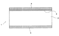
図1は、広幅の磁気テープが、その長手方向に沿って、理想的に裁断されて、生成された磁気テープの略横断面図である。
【0028】
本実施態様にかかる磁気テープ1は、コンピュータ用データバックアップテープとして用いられ、図1に示されるように、コンピュータ用データバックアップテープ1は、支持体2を備え、支持体2の一方の面には、アンダーコート層3と、データを記録する磁気記録層4が形成され、他方の面には、バックコート層5が形成されている。
【0029】
本実施態様においては、コンピュータ用データバックアップテープ1の支持体2は、6.0ないし6.5μm、好ましくは、6.1ないし6.3μmの厚さを有し、支持体2の一方の面に、0.5ないし2.5μmの厚さのアンダーコート層3と、0.05ないし0.5μmの厚さの磁気記録層4が形成され、支持体2の他方の面に、0.4ないし0.7μmの厚さのバックコート層5が形成されている。
【0030】
図1に示されたコンピュータ用データバックアップテープ1は、広幅の支持体2の一方の面に、塗布などにより、アンダーコート層3および磁気記録層4が形成され、支持体2の他方の面に、塗布などにより、バックコート層5が形成された広幅の磁気テープ(図示せず)が、その長手方向に、所定の幅に裁断されて、形成される。
【0031】
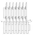
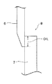
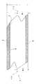
図2は、本発明の好ましい実施態様にかかる磁気テープ裁断装置の略横断面図であり、図3は、図2において、Aで示された部分の略一部拡大断面図である。
【0032】
図2に示されるように、本実施態様にかかる磁気テープ裁断装置は、約6.2μmの厚さを有する広幅の支持体2の一方の面に、約2μmの厚さのアンダーコート層3と、約0.15μmの厚さの磁気記録層4が形成され、支持体2の他方の面に、約0.5μmの厚さのバックコート層5が形成された広幅の磁気テープ(図示せず)を、所定の幅に裁断して、コンピュータ用データバックアップテープ1を製造可能に構成され、それぞれが、円板状の上刃6と、円板状の下刃7を備えた複数の裁断ユニット8を備えており、各裁断ユニット8の円板状の上刃6および下刃7は、回転可能に構成されている。
【0033】
図3に示されるように、本実施態様においては、上刃6として、下刃7に対向する面が、下刃7の上刃6に対向する面と略平行で、下刃7に対向する面と反対側の面に、先端部に向かうにつれて、上刃6の厚さが減少するように、傾斜面が形成された上刃6が用いられている。
【0034】
図3において、OLは、上刃6と下刃7のオーバーラップしている部分の長さである。
【0035】
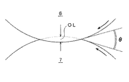
図4は、図1に示された磁気テープ裁断装置を構成する各裁断ユニット8の略縦断面図である。
【0036】
図4に示されるように、本実施態様にかかる磁気テープ裁断装置を構成する各裁断ユニット8においては、円板状の上刃6と、円板状の下刃7は、互いに反対向きに回転され、広幅の磁気テープは、磁気記録層4が上刃側に位置し、バックコート層5が下刃側に位置するように、円板状の上刃6と円板状の下刃7の間に供給され、磁気テープ裁断装置を構成する隣り合った裁断ユニット8の上刃6と下刃7によって、広幅の磁気テープが所定の幅に裁断されて、コンピュータ用データバックアップテープ1が製造される。
【0037】
図5は、広幅の磁気テープが、その長手方向に沿って、所定の幅に裁断されて、生成されたコンピュータ用データバックアップテープ1の略横断面図である。
【0038】
図5に示されるように、広幅の磁気テープが、その長手方向に沿って、所定の幅に裁断されて、生成されたコンピュータ用データバックアップテープ1の支持体2の上刃側の裁断面には、その不規則な凹凸パターンが極大になる上刃側突出部10が形成され、一方、支持体2の下刃側の裁断面には、その不規則な凹凸パターンが極大になる下刃側突出部11が形成される。
【0039】
コンピュータ用データバックアップテープ1の磁気記録層4へのデータの記録にあたっては、コンピュータ用データバックアップテープ1の両側面、すなわち、両裁断面が、データ記録装置のガイド部材によってガイドされて、コンピュータ用データバックアップテープ1がデータ記録装置内を送られ、一方、コンピュータ用データバックアップテープ1の磁気記録層4に記録されたデータの再生にあたっては、コンピュータ用データバックアップテープ1の両裁断面が、データ再生装置のガイド部材によってガイドされて、コンピュータ用データバックアップテープ1がデータ再生装置内を送られるように構成されている。
【0040】
したがって、コンピュータ用データバックアップテープ1の裁断面に、不規則で、大きな凹凸パターンが形成されているときは、データの記録時あるいはデータの再生時に、データ記録装置あるいはデータ再生装置のガイド部材が、コンピュータ用データバックアップテープ1の裁断面の突出部に接触することに起因して、裁断面の突出部が、コンピュータ用データバックアップテープ1から脱落するという不具合を生ずるおそれがある。
【0041】
しかしながら、本発明者の研究によれば、驚くべきことに、上刃6と下刃7によって、広幅の磁気テープが裁断されて、形成されたコンピュータ用データバックアップテープ1の支持体2の上刃6側の裁断面の不規則な凹凸パターンが極大になる位置、すなわち、上刃側突出部10の位置、あるいは、支持体2の下刃7側の裁断面の不規則な凹凸パターンが極大になる位置、すなわち、下刃側突出部11の位置が、40≦BU/T×100≦70あるいは40≦BL/T×100≦70(ここに、BUは、バックコート層5の表面から、支持体2の上刃6側の裁断面の不規則な凹凸パターンが極大になる位置、すなわち、上刃側突出部10の位置までの距離であり、BLは、バックコート層5の表面から、支持体2の下刃7側の裁断面の不規則な凹凸パターンが極大になる位置、すなわち、下刃側突出部11の位置までの距離、Tは広幅の磁気テープの全厚、すなわち、コンピュータ用データバックアップテープ1の全厚である。)を満足している場合には、コンピュータ用データバックアップテープ1の厚さ方向における支持体2の上刃6側の裁断面の不規則な凹凸パターンが極大になる位置、すなわち、上刃側突出部10の位置と、支持体2の下刃7側の裁断面の不規則な凹凸パターンが極大になる位置、すなわち、下刃側突出部11の位置とがほぼ一致し、したがって、コンピュータ用データバックアップテープ1にデータを記録する際に、コンピュータ用データバックアップテープ1をガイドするデータ記録装置のガイド部材によって、コンピュータ用データバックアップテープ1の両裁断面をガイドしたとき、あるいは、コンピュータ用データバックアップテープ1からデータを再生する際に、コンピュータ用データバックアップテープ1をガイドするデータ再生装置のガイド部材によって、コンピュータ用データバックアップテープ1の両裁断面をガイドしたときに、それぞれ、コンピュータ用データバックアップテープ1の両裁断面を、同じように、データ記録装置あるいはデータ再生装置のガイド部材に当接させ、磁気テープを安定して、走行させることが可能になり、その結果、コンピュータ用データバックアップテープ1の両裁断面の不規則な凹凸パターンのいかんにかかわらず、データの記録時あるいはデータの再生時に、コンピュータ用データバックアップテープ1の両裁断面の不規則な凹凸パターンに起因して、コンピュータ用データバックアップテープ1の裁断面の一部が剥離して、脱落することを効果的に防止し得ることが見出されるとともに、互いにオーバーラップし、反対向きに回転する円板状の上刃6と円板状の下刃7との間に供給された広幅の磁気テープの裁断が開始されるときの円板状の上刃6と円板状の下刃7のなす角度(以下、「裁断開始角度」という)θを制御することによって、コンピュータ用データバックアップテープ1の両裁断面の不規則な凹凸パターンが極大になる位置を制御することが可能になることが見出された。
【0042】
したがって、本実施態様においては、上刃6と下刃7によって、広幅の磁気テープが裁断されて、形成されるべきコンピュータ用データバックアップテープ1の支持体2の上刃6側の裁断面の不規則な凹凸パターンが極大になる位置、すなわち、上刃側突出部10の位置、あるいは、支持体2の下刃7側の裁断面の不規則な凹凸パターンが極大になる位置、すなわち、下刃側突出部11の位置が、40≦BU/T×100≦70あるいは40≦BL/T×100≦70を満足するように、上刃6の下刃7のなす裁断開始角度θが設定されている。
【0043】
その結果、上刃6と下刃7により、広幅の磁気テープを裁断して、得られたコンピュータ用データバックアップテープ1においては、コンピュータ用データバックアップテープ1の厚さ方向における支持体2の上刃6側の裁断面の不規則な凹凸パターンが極大になる位置、すなわち、上刃側突出部10の位置と、支持体2の下刃7側の裁断面の不規則な凹凸パターンが極大になる位置、すなわち、下刃側突出部11の位置とがほぼ一致しており、コンピュータ用データバックアップテープ1にデータを記録する際あるいはコンピュータ用データバックアップテープ1からデータを再生する際に、コンピュータ用データバックアップテープ1をガイドするデータ記録装置あるいはデータ再生装置のガイド部材によって、コンピュータ用データバックアップテープ1の両裁断面をガイドしたときに、コンピュータ用データバックアップテープ1の両裁断面を、同じように、データ記録装置あるいはデータ再生装置のガイド部材に当接させ、磁気テープを安定して、走行させることが可能になるから、コンピュータ用データバックアップテープ1の両裁断面の不規則な凹凸パターンのいかんにかかわらず、データの記録時あるいはデータの再生時に、コンピュータ用データバックアップテープ1の両裁断面の不規則な凹凸パターンに起因して、コンピュータ用データバックアップテープ1の裁断面の一部が剥離して、脱落するという不具合が生じることを効果的に防止することが可能になる。
【0044】
好ましくは、上刃6と下刃7によって広幅の磁気テープが裁断されて、形成されたコンピュータ用データバックアップテープ1の支持体2の上刃6側の裁断面の不規則な凹凸パターンが極大になる位置、すなわち、上刃側突出部10の位置、あるいは、支持体2の下刃7側の裁断面の不規則な凹凸パターンが極大になる位置、すなわち、下刃側突出部11の位置が、0.9≦(BU/T)/(BL/T)≦1.1を満たしており、上刃6と下刃7によって、広幅の磁気テープが裁断されて、形成されるべきコンピュータ用データバックアップテープ1の支持体2の上刃6側の裁断面の不規則な凹凸パターンが極大になる位置あるいは支持体2の下刃7側の裁断面の不規則な凹凸パターンが極大になる位置が、0.9≦(BU/T)/(BL/T)≦1.1を満たすように、上刃6と下刃7のなす裁断開始角度θが設定されて、コンピュータ用データバックアップテープ1が製造される。
【0045】
具体的には、上刃6と下刃7のなす裁断開始角度θは、7°ないし12°、好ましくは、7°ないし10°に設定される。
【0046】
ここに、上刃6と下刃7のなす裁断開始角度θは、上刃6と下刃7のオーバーラップしている部分の長さOLを調整することによって、設定される。
【0047】
【実施例】
以下、本発明の効果を、より一層明らかにするため、実施例を掲げる。
【0048】
実施例
幅500mmで、6.1μmの厚さのポリエチレンナフタレート製の広幅の支持体2の一方の面に、2μmの厚さのアンダーコート層3と、0.15μmの厚さの磁気記録層4を形成するとともに、支持体2の他方の面に、0.5μmの厚さのバックコート層5を形成して、広幅の磁気テープを製造した。
【0049】
次いで、それぞれ、径が150mmの上刃6および下刃7を備えた一対の裁断ユニット8を用いて、広幅の磁気テープを裁断して、幅12.65mmのコンピュータ用データバックアップテープ1を生成した。
【0050】
ここに、上刃6としては、上刃6の下刃7に対向する面が、下刃7の上刃6に対向する面と略平行で、下刃7に対向する面と反対側の面に、先端部に向かうにつれて、上刃6の厚さが減少するように、傾斜面が形成された上刃6を用い、一対の裁断ユニットの上刃6と下刃7のオーバーラップしている部分の長さOLを変化させて、上刃6と下刃7のなす裁断開始角度θを変化させ、それぞれの場合に、広幅の磁気テープが裁断されて、生成されたコンピュータ用データバックアップテープ1の両裁断面の厚さ方向の不規則な凹凸パターンを観察し、支持体2の上刃6側の裁断面の不規則な凹凸パターンが極大となる位置および支持体2の下刃7側の裁断面の不規則な凹凸パターンが極大になる位置を求めた。
【0051】
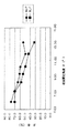
図6は、バックコート層5の表面から、支持体2の上刃6側の裁断面の不規則な凹凸パターンが極大になる位置までの距離BUを、コンピュータ用データバックアップテープ1の全厚Tにより除した値(百分率)と上刃6と下刃7のなす裁断開始角度θとの関係および支持体2の下刃7側の裁断面の不規則な凹凸パターンが極大になる位置までの距離BLを、コンピュータ用データバックアップテープ1の全厚Tにより除した値(百分率)と上刃6と下刃7のなす裁断開始角度θとの関係を示すグラフである。
【0052】
図6から、支持体2の上刃6側の裁断面の不規則な凹凸パターンが極大になる位置および支持体2の下刃7側の裁断面の不規則な凹凸パターンが極大になる位置は、上刃6と下刃7のなす裁断開始角度θにしたがって、変化するが、バックコート層5の表面から、支持体2の上刃6側の裁断面の不規則な凹凸パターンが極大になる位置までの距離BUを、コンピュータ用データバックアップテープ1の全厚Tによって除した値(百分率)が、40%ないし70%の範囲にあるときに、バックコート層5の表面から、支持体2の上刃6側の裁断面の不規則な凹凸パターンが極大になる位置までの距離BUを、コンピュータ用データバックアップテープ1の全厚Tにより除した値(百分率)と、支持体2の下刃7側の裁断面の不規則な凹凸パターンが極大になる位置までの距離BLを、コンピュータ用データバックアップテープ1の全厚Tにより除した値(百分率)とがほぼ一致し、したがって、支持体2の上刃6側の裁断面の不規則な凹凸パターンが極大になる位置と、支持体2の下刃7側の裁断面の不規則な凹凸パターンが極大になる位置とがほぼ一致することがわかる。
【0053】
したがって、バックコート層5の表面から、支持体2の上刃6側の裁断面の不規則な凹凸パターンが極大になる位置までの距離BUを、コンピュータ用データバックアップテープ1の全厚Tにより除した値(百分率)が、40%ないし70%の範囲になるように、上刃6と下刃7のなす裁断開始角度θを設定して、広幅の磁気テープを裁断し、コンピュータ用データバックアップテープ1を生成することによって、コンピュータ用データバックアップテープ1にデータを記録する際あるいはコンピュータ用データバックアップテープ1からデータを再生する際に、コンピュータ用データバックアップテープ1をガイドするデータ記録装置あるいはデータ再生装置のガイド部材によって、コンピュータ用データバックアップテープ1の両裁断面をガイドしたときに、コンピュータ用データバックアップテープ1の両裁断面を、同じように、データ記録装置あるいはデータ再生装置のガイド部材に当接させて、コンピュータ用データバックアップテープ1を安定して、走行させることができるから、コンピュータ用データバックアップテープ1の両裁断面の不規則な凹凸パターンのいかんにかかわらず、データの記録時あるいはデータの再生時に、コンピュータ用データバックアップテープ1の両裁断面の不規則な凹凸パターンに起因して、コンピュータ用データバックアップテープ1の裁断面の一部が剥離して、脱落するという不具合が生じることを効果的に防止し得ることが判明した。
【0054】
また、図6から、上刃6と下刃7のなす裁断開始角度θを、7°ないし12°に設定して、広幅の磁気テープを裁断し、コンピュータ用データバックアップテープ1を生成した場合に、バックコート層5の表面から、支持体2の上刃6側の裁断面の不規則な凹凸パターンが極大になる位置までの距離BUを、コンピュータ用データバックアップテープ1の全厚Tにより除した値(百分率)が、40%ないし70%になるとともに、バックコート層5の表面から、支持体2の下刃7側の裁断面の不規則な凹凸パターンが極大になる位置までの距離BLを、コンピュータ用データバックアップテープ1の全厚Tによって除した値(百分率)も、40%ないし70%になり、上刃6と下刃7のなす裁断開始角度θを7°ないし12°に設定することが好ましいことが判明した。
【0055】
さらに、上刃6と下刃7のなす裁断開始角度θを、7°ないし10°に設定して、広幅の磁気テープを裁断し、コンピュータ用データバックアップテープ1を生成した場合には、支持体2の上刃6側の裁断面の不規則な凹凸パターンが極大になる位置と、支持体2の下刃7側の裁断面の不規則な凹凸パターンが極大になる位置とが、より一層近接し、その結果、コンピュータ用データバックアップテープ1にデータを記録する際あるいはコンピュータ用データバックアップテープ1からデータを再生する際に、コンピュータ用データバックアップテープ1をガイドするデータ記録装置あるいはデータ再生装置のガイド部材によって、コンピュータ用データバックアップテープ1の両裁断面をガイドしたときに、コンピュータ用データバックアップテープ1の両裁断面を、より一層同一に近い態様で、データ記録装置あるいはデータ再生装置のガイド部材に当接させて、コンピュータ用データバックアップテープ1をきわめて安定して、走行させることができるから、コンピュータ用データバックアップテープ1の両裁断面の不規則な凹凸パターンのいかんにかかわらず、データの記録時あるいはデータの再生時に、コンピュータ用データバックアップテープ1の両裁断面の不規則な凹凸パターンに起因して、コンピュータ用データバックアップテープ1の裁断面の一部が剥離して、脱落するという不具合が生じることを確実に防止し得ることが判明した。
【0056】
実施例2
幅500mmで、6.1μmの厚さのポリエチレンナフタレート製の広幅の支持体2の一方の面に、2μmの厚さのアンダーコート層3と、0.15μmの厚さの磁気記録層4を形成するとともに、支持体2の他方の面に、0.5μmの厚さのバックコート層5を形成して、広幅の磁気テープを製造した。
【0057】
次いで、それぞれ、径が150mmの上刃6および下刃7を備えた一対の裁断ユニット8を用いて、広幅の磁気テープを裁断して、幅12.65mmのコンピュータ用データバックアップテープ1を生成した。
【0058】
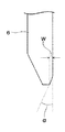
ここに、図7に示されるように、上刃6として、上刃6の下刃7に対向する面が、下刃7の上刃6に対向する面との角度αが4.5°で、面取り幅Wが0.5μmとなるように、面取りされ、下刃7に対向する面と反対側の上刃6の面に、先端部に向かうにつれて、上刃6の厚さが減少するように、傾斜面が形成された上刃6を用い、一対の裁断ユニットの上刃6と下刃7のオーバーラップしている部分の長さOLを変化させて、上刃6と下刃7のなす裁断開始角度θを変化させ、それぞれの場合に、磁気テープが裁断されて、生成されたコンピュータ用データバックアップテープ1の両裁断面の厚さ方向の不規則な凹凸パターンを観察し、支持体2の上刃6側の裁断面の不規則な凹凸パターンが極大になる位置および支持体2の下刃7側の裁断面の不規則な凹凸パターンが極大になる位置を求めた。
【0059】
その結果、上刃6として、面取りされていない上刃6を用いた場合と同様な結果が得られた。
【0060】
本発明は、以上の実施態様に限定されることなく、特許請求の範囲に記載された発明の範囲内で種々の変更が可能であり、それらも本発明の範囲内に包含されるものであることはいうまでもない。
【0061】
たとえば、前記実施態様および前記実施例においては、広幅の磁気テープを裁断して、コンピュータ用データバックアップテープを製造する場合につき、説明を加えたが、本発明は、広幅の磁気テープを裁断して、コンピュータ用データバックアップテープを製造する場合に限定されるものではなく、広幅の磁気テープを裁断して、オーディオ用磁気テープ、ビデオ用磁気テープ、8mmビデオ用磁気テープなど、広く、磁気テープ一般を製造する場合にも適用することができ、磁気記録層4が単層の場合だけでなく、多層の磁気記録層4を備えた磁気テープを製造する場合にも適用することができる。
【0062】
また、前記実施態様においては、上刃6の下刃7に対向する面が、下刃7の上刃6に対向する面と略平行で、下刃7に対向する面と反対側の上刃6の面に、先端部に向かうにつれて、上刃6の厚さが減少するように、傾斜面が形成された上刃6を用いて、広幅の磁気テープを裁断して、コンピュータ用データバックアップテープ1を製造しているが、実施例2と同様に、上刃6として、上刃6の下刃7に対向する面が、下刃7の上刃6に対向する面との角度αが4.5°で、面取り幅Wが0.5μmとなるように、面取りされ、下刃7に対向する面と反対側の上刃6の面に、先端部に向かうにつれて、上刃6の厚さが減少するように、傾斜面が形成された上刃6を用いて、広幅の磁気テープを裁断して、コンピュータ用データバックアップテープ1を製造するようにしてもよい。
【0063】
さらに、前記実施例2においては、下刃7に対向する面が、下刃7の上刃6に対向する面との角度αが4.5°で、面取り幅Wが0.5μmとなるように、面取りされ、下刃7に対向する面と反対側の面に、先端部に向かうにつれて、上刃6の厚さが減少するように、傾斜面が形成された上刃6を用いて、広幅の磁気テープを裁断して、コンピュータ用データバックアップテープを製造しているが、面取りされた上刃6を用いる場合に、下刃7に対向する面が、下刃7の上刃6に対向する面との角度αが4.5°で、面取り幅Wが0.5μmとなるように、面取りされた上刃6を用いることは必ずしも必要でない。
【0064】
【発明の効果】
本発明によれば、互いにオーバーラップし、反対向きに回転する円板状の上刃と下刃の間に、広幅の磁気テープを供給し、その長手方向に沿って、広幅の磁気テープを裁断して、得られる磁気テープの裁断面の不規則な凹凸パターンに起因して、データの記録時あるいはデータの再生時に、磁気テープの裁断面の一部が剥離して、脱落することを効果的に防止することができる磁気テープおよびその製造方法を提供することが可能になる。
【図面の簡単な説明】
【図1】図1は、広幅の磁気テープが、その長手方向に沿って、理想的に裁断されて、生成されたコンピュータ用データバックアップテープの略横断面図である。
【図2】図2は、本発明の好ましい実施態様にかかる磁気テープ裁断装置の略横断面図である。
【図3】図3は、図2において、Aで示された部分の略一部拡大断面図である。
【図4】図3は、図1に示された磁気テープ裁断装置を構成する各裁断ユニットの略縦断面図である。
【図5】図5は、広幅の磁気テープが、その長手方向に沿って、裁断されて、生成されたコンピュータ用データバックアップテープの略横断面図である。
【図6】図6は、バックコート層の表面から、支持体の上刃側の裁断面の不規則な凹凸パターンが極大になる位置までの距離BUを、コンピュータ用データバックアップテープの全厚Tにより除した値(百分率)と上刃と下刃のなす裁断開始角度θとの関係および支持体の下刃側の裁断面の不規則な凹凸パターンが極大になる位置までの距離BLを、コンピュータ用データバックアップテープの全厚Tによって除した値(百分率)と上刃と下刃のなす裁断開始角度θとの関係を示すグラフである。
【図7】図7は、上刃および下刃の略拡大断面図である。
【符号の説明】
1 コンピュータ用データバックアップテープ
2 支持体
3 アンダーコート層
4 磁気記録層
5 バックコート層
6 上刃
7 下刃
8 裁断ユニット
10 上刃側突出部
11 下刃側突出部[0001]
TECHNICAL FIELD OF THE INVENTION
The present invention relates to a magnetic tape and a method for manufacturing the same, and more particularly, to supply a wide magnetic tape between a disk-shaped upper blade and a lower blade that overlap with each other and rotate in opposite directions. Along the longitudinal direction, a wide magnetic tape is cut, and due to an irregular pattern of irregularities of the obtained magnetic tape cut surface, when recording data or reproducing data, the cut surface of the magnetic tape is cut. The present invention relates to a magnetic tape capable of effectively preventing a part of the tape from coming off and falling off, and a method for manufacturing the same.
[0002]
[Prior art]
Normally, the magnetic tape has a magnetic recording layer formed on one surface of a wide support, a back coat layer formed on the other surface, and then between a rotating upper blade and a lower blade of the cutting device. It is manufactured by supplying a wide magnetic tape and cutting it to the width of the product.
[0003]
However, in the case where a wide magnetic tape is supplied between the upper and lower blades of a disk that overlap with each other and rotate in opposite directions, and cut to the width of a product, and a magnetic tape is manufactured, It is known that an irregular concavo-convex pattern is likely to occur on a cut surface, and when an irregular, large concavo-convex pattern occurs on a cut surface of a magnetic tape, the cut surface of the magnetic tape becomes a guide surface. Therefore, when recording data on the magnetic tape, the guide member of the data recording device that guides the magnetic tape guides the cut surface of the magnetic tape, or when reproducing data from the magnetic tape, the magnetic tape is used. When the cut surface of the magnetic tape is guided by the guide member of the data reproducing device to be guided, a problem occurs that a part of the cut surface falls off the cut surface of the magnetic tape. Have it.
[0004]
[Problems to be solved by the invention]
Conventionally, a wide magnetic tape was cut to cut the wide magnetic tape and to manufacture the magnetic tape so as to prevent the occurrence of such a defect and reduce the irregular uneven pattern of the cut surface of the magnetic tape. Methods of adjusting the degree of overlap between the disk-shaped upper blade and the disk-shaped lower blade to be cut and chamfering the upper blade or the lower blade have been proposed.
[0005]
By such a method, the irregular concavo-convex pattern of the cut surface of the magnetic tape can be improved to some extent, but in order to improve the irregular concavo-convex pattern of the cut surface of the magnetic tape, a disc to be set must be set. The degree of overlap between the disk-shaped upper blade and the disk-shaped lower blade depends on the diameter of the disk-shaped upper blade and the disk-shaped lower blade, and differs from the disk-shaped upper blade used for cutting. It is indispensable to experimentally set the degree of overlap between the disk-shaped upper blade and the disk-shaped lower blade according to the diameter of the plate-shaped lower blade. Simply chamfering the blade cannot sufficiently improve the irregular pattern of the cut surface of the magnetic tape, so a part of the cut surface is caused by the irregular pattern of the cut surface of the magnetic tape. It has been desired to develop a method capable of effectively preventing the falling off.
[0006]
Therefore, the present invention provides a wide magnetic tape between the upper blade and the lower blade, which are mutually overlapping and rotate in opposite directions, and cuts the wide magnetic tape along the longitudinal direction. Then, due to the irregular concavo-convex pattern of the cut surface of the magnetic tape obtained, it is possible to effectively prevent a part of the cut surface of the magnetic tape from peeling and falling off during data recording or data reproduction. It is an object of the present invention to provide a magnetic tape and a method for manufacturing the same, which can prevent the occurrence of a magnetic tape.
[0007]
[Means for Solving the Problems]
The inventor of the present invention has conducted intensive studies in order to achieve the object of the present invention. As a result, a wide magnetic tape is cut by an upper blade and a lower blade, and the upper blade side of the formed magnetic tape support is formed. The position where the irregular concavo-convex pattern of the cut surface of the above becomes maximal or the position where the irregular concavo-convex pattern of the cut surface on the lower blade side becomes the maximum is 40 ≦ BU / T × 100 ≦ 70 or 40 ≦ BL / T × 100 ≦ 70 (where BU is the distance from the surface of the back coat layer to the position where the irregular asperity pattern of the cut surface on the upper blade side of the support becomes maximum, and BL is the back coat layer When the distance from the surface to the position where the irregular asperity pattern of the cut surface on the lower blade side of the support is maximized, T is the total thickness of the wide magnetic tape, is surprising. In particular, on the support in the thickness direction of the magnetic tape The position where the irregular uneven pattern of the cutting surface on the blade side is maximized almost coincides with the position where the irregular uneven pattern of the cutting surface on the lower blade side of the support is maximized. When recording data, the guide member of the data recording device that guides the magnetic tape guides the double-sided section of the magnetic tape, or reproduces data from the magnetic tape when reproducing data from the magnetic tape. When the double-sided section of the magnetic tape is guided by the guide member of the device, the double-sided section of the magnetic tape is similarly brought into contact with the guide member of the data recording device or the guide member of the data reproducing device, and It is possible to run the machine stably, regardless of the irregular concavo-convex pattern of the cut surface, when recording data or reproducing data, Due to the irregular raised and depressed pattern of the cut surface of the-loop, part of the cut surface of the magnetic tape is peeled off, were found to be effectively prevented from falling off.
[0008]
According to the study of the present inventor, a wide magnetic tape is cut by a disk-shaped upper blade and a disk-shaped lower blade which overlap with each other and rotate in opposite directions to support the generated magnetic tape. The position where the irregular asperity pattern of the cut surface on the upper blade side of the body becomes maximal or the position where the irregular asperity pattern of the cut surface on the lower blade side of the support becomes maximal is BU / T × 100 <40 or In the case of BL / T × 100 <40, and at the position where the irregular asperity pattern of the cut surface on the upper blade side of the support becomes maximal or the irregular asperity pattern of the cut surface on the lower blade side of the support is maximal Is BU / T × 100> 70 or BL / T × 100> 70, the irregular asperity pattern of the cut surface on the upper blade side of the support becomes maximum in any case. The position and irregularity of the cutting surface on the lower blade side of the support The position at which the magnetic field is maximized greatly deviates from the thickness direction of the magnetic tape.Therefore, when recording data on the magnetic tape or reproducing data from the magnetic tape, the data that guides the magnetic tape is used. When the double-sided section of the magnetic tape is guided by the guide member of the recording apparatus or the data reproducing apparatus, the double-sided section of the magnetic tape is similarly applied to the guide member of the data recording apparatus or the guide member of the data reproducing apparatus. The magnetic tape cannot run stably, and as a result, when recording data on the magnetic tape or reproducing data from the magnetic tape, a data recording device or data guiding the magnetic tape is used. Due to the fact that the guide member of the reproducing device comes into contact with the cut surface of the magnetic tape, the protrusions on both cut surfaces are It has been found that a problem of peeling off from the surface and falling off occurs.
[0009]
Therefore, the object of the present invention is to overlap a wide magnetic tape in which a magnetic recording layer is formed on one surface of a wide support and a back coat layer is formed on the other surface, and the wide magnetic tapes overlap each other. Supply between the disk-shaped upper blade rotating in the direction and the disk-shaped lower blade, cut to a predetermined width, irregularities in the cut surface of the upper blade side of the manufactured magnetic tape support The position where the concave / convex pattern is maximal or the position where the irregular concave / convex pattern of the cut surface on the lower blade side is maximal is 40 ≦ BU / T × 100 ≦ 70 or 40 ≦ BL / T × 100 ≦ 70 (where, BU is the distance from the surface of the back coat layer to the position where the irregular asperity pattern of the cut surface on the upper blade side of the support is maximized, and BL is the distance from the surface of the back coat layer to the position below the support. To the position where the irregular asperity pattern of the cutting surface on the blade side is maximized. Where T is the total thickness of the wide magnetic tape.)
[0010]
In this specification, the cutting surface of the upper blade side of the magnetic tape refers to the cutting surface of the magnetic tape that is in contact with the upper blade after cutting the magnetic tape, and the cutting surface of the lower blade side of the magnetic tape is Refers to the cut surface of the magnetic tape in contact with the lower blade after cutting the magnetic tape.
[0011]
According to the study of the present inventor, a wide magnetic tape is cut by a disk-shaped upper blade and a disk-shaped lower blade which overlap with each other and rotate in opposite directions to support the generated magnetic tape. The position at which the irregular asperity pattern of the cut surface on the upper blade side of the body becomes maximal or the position at which the irregular asperity pattern of the cut surface on the lower blade side of the support becomes maximal is BU / T and BL / T. In the case where the ratio is less than 0.9 and the ratio of BU / T and BL / T exceeds 1.1, in either case, When reproducing data from a magnetic tape, when a double-sided section of the magnetic tape is guided by a data recording device or a guide member of the data reproducing device that guides the magnetic tape, the double-sided section of the magnetic tape is similarly set. , Data recording device It is difficult to make the magnetic tape run stably by contacting the magnetic member or the guide member of the data reproducing apparatus. As a result, when recording data on the magnetic tape or reproducing data from the magnetic tape, The guide member of the data recording device or the data reproducing device that guides the magnetic tape comes into contact with the cut surface of the magnetic tape, so that the protrusions of the cut surfaces are peeled off from the cut surface of the magnetic tape, It has been found that a problem of dropping occurs.
[0012]
On the other hand, according to the research of the present inventor, a wide magnetic tape is cut by a disk-shaped upper blade and a disk-shaped lower blade which overlap with each other and rotate in opposite directions, and are generated. The position where the irregular concavo-convex pattern of the cut surface on the upper blade side of the magnetic tape support becomes maximal or the position where the irregular concavo-convex pattern of the cut surface on the lower blade side of the support becomes maximal is BU / T. And when the ratio of BL / T is 0.9 to 1.1, the data recording that guides the magnetic tape when recording data on the magnetic tape or reproducing data from the magnetic tape. When the double-sided section of the magnetic tape is guided by the guide member of the device or the data reproducing apparatus, the double-sided section of the magnetic tape is similarly brought into contact with the guide member of the data recording apparatus or the data reproducing apparatus, The It can be run very stably, regardless of the irregular pattern of the cut surface, regardless of the irregular pattern of the cut surface, due to the irregular pattern of the cut surface of the magnetic tape when recording or reproducing data. It has been found that a part of the cut surface of the magnetic tape can be reliably prevented from peeling and falling off.
[0013]
Therefore, in a preferred embodiment of the present invention, the BU / T and the BL / T satisfy 0.9 ≦ (BU / T) / (BL / T) ≦ 1.1.
[0014]
Further, according to the study of the present inventor, the cutting of the wide magnetic tape supplied between the disk-shaped upper blade and the disk-shaped lower blade that overlap with each other and rotate in opposite directions is started. Surprisingly, by controlling the cutting start angle between the disc-shaped upper blade and the disc-shaped lower blade when the tape is cut, the cut surface of the upper blade side of the support in the thickness direction of the magnetic tape is not properly adjusted. The irregular asperity pattern of the cut surface of the magnetic tape is such that the position where the regular asperity pattern becomes maximal and the position where the irregular asperity pattern of the cut surface on the lower blade side of the support become substantially the same. It has been found that can be controlled.
[0015]
Therefore, the object of the present invention is also to overlap a wide magnetic tape having a magnetic recording layer formed on one surface of a wide support and a back coat layer formed on the other surface thereof, A method of manufacturing a magnetic tape for supplying a magnetic tape between a disk-shaped upper blade and a disk-shaped lower blade rotating in opposite directions, cutting the same to a predetermined width, and manufacturing the magnetic tape. By the lower blade, the wide magnetic tape is cut, and a position where the irregular concavo-convex pattern of the upper taper side cut surface of the magnetic tape to be formed becomes maximum or the lower blade side cut surface. The position where the irregular uneven pattern is maximized is 40 ≦ BU / T × 100 ≦ 70 or 40 ≦ BL / T × 100 ≦ 70 (where BU is the surface of the back coat layer from the support. The irregular cutting pattern of the cutting surface on the upper blade side Is the distance from the surface of the back coat layer to the position where the irregular asperity pattern of the cut surface on the lower blade side of the support becomes the maximum, T is the total thickness of the wide magnetic tape.) The tape is supplied between the disc-shaped upper blade and the disc-shaped lower blade which are overlapped with each other and rotate in opposite directions. Setting the cutting start angle between the disk-shaped upper blade and the disk-shaped lower blade when the cutting of the wide magnetic tape is started, cutting the wide magnetic tape, and magnetic tape Is achieved by a method for manufacturing a magnetic tape, which comprises:
[0016]
In a preferred embodiment of the present invention, the BU / T and the BL / T overlap with each other and rotate in opposite directions so that the ratio of the BU / T is 0.9 to 1.1. The cutting start angle formed by the disk-shaped upper blade and the disk-shaped lower blade when the cutting of the wide magnetic tape supplied between the blade and the disk-shaped lower blade is started. The magnetic tape is manufactured by setting and cutting the wide magnetic tape.
[0017]
In a preferred embodiment of the present invention, cutting of the wide magnetic tape supplied between the disk-shaped upper blade and the disk-shaped lower blade which overlap with each other and rotate in opposite directions starts. The cutting start angle formed by the disc-shaped upper blade and the disc-shaped lower blade when the cutting is performed is set to 7 ° to 12 °, and the wide magnetic tape is cut to manufacture a magnetic tape. It is configured as follows.
[0018]
According to the study of the present inventor, when cutting of the wide magnetic tape supplied between the disk-shaped upper blade and the disk-shaped lower blade overlapping each other and rotating in opposite directions is started. When the cutting start angle formed by the disc-shaped upper blade and the disc-shaped lower blade is set to an angle of less than 7 °, a wide magnetic tape is cut, and a magnetic tape is manufactured, and the cutting start angle Is set to an angle exceeding 12 °, a wide magnetic tape is cut, and in the case where a magnetic tape is manufactured, in any case, the cut surface on the upper blade side of the support of the generated magnetic tape. The position at which the irregular asperity pattern becomes maximal and the position at which the irregular asperity pattern of the cut surface on the lower blade side of the support becomes maximal are greatly displaced with respect to the thickness direction of the magnetic tape. When recording data on magnetic tape or re-reading data from magnetic tape. When a double-sided section of a magnetic tape is guided by a guide member of a data recording device or a data reproducing apparatus that guides a magnetic tape when producing a magnetic tape, the double-sided section of the magnetic tape is similarly moved to the data recording apparatus. The magnetic tape cannot run stably by contacting the guide member or the guide member of the data reproducing apparatus. As a result, when recording data on the magnetic tape or reproducing data from the magnetic tape, Due to the fact that the guide member of the data recording device or the data reproducing device that guides the magnetic tape comes into contact with the cut surface of the magnetic tape, the protrusions of both cut surfaces are separated from the cut surface of the magnetic tape and fall off. Has been found to occur.
[0019]
On the other hand, according to the research of the present inventor, according to the research of the present invention, the cutting of the wide magnetic tape supplied between the disk-shaped upper blade and the disk-shaped lower blade which overlap each other and rotate in opposite directions. When the cutting start angle formed by the disc-shaped upper blade and the disc-shaped lower blade when starting is set to 7 ° to 12 °, a wide magnetic tape is cut, and a magnetic tape is manufactured. Surprisingly, the position where the irregular asperity pattern of the cut surface on the upper blade side of the support becomes maximal, and the position where the irregular asperity pattern of the cut surface on the lower blade side of the support becomes maximal Is almost at the same position in the thickness direction of the magnetic tape, and as a result, when recording data on the magnetic tape or reproducing data from the magnetic tape, a data recording device or data guiding the magnetic tape is used. Both guides of the magnetic tape are When the cut surface is guided, the two cut surfaces of the magnetic tape are similarly brought into contact with the guide member of the data recording device or the data reproducing device, so that the magnetic tape can run stably, Irrespective of the irregular uneven pattern of the magnetic tape, when recording data or reproducing data, a part of the cut surface of the magnetic tape may peel off due to the irregular uneven pattern of the magnetic tape. Have been found to be effectively prevented from falling off.
[0020]
In a further preferred embodiment of the present invention, cutting of the wide magnetic tape supplied between the disk-shaped upper blade and the disk-shaped lower blade that overlap with each other and rotate in opposite directions is performed. When the cutting start angle formed by the disc-shaped upper blade and the disc-shaped lower blade at the start is set to 7 ° to 10 °, the wide magnetic tape is cut to manufacture a magnetic tape. It is configured to
[0021]
According to the study of the present inventor, when cutting of the wide magnetic tape supplied between the disk-shaped upper blade and the disk-shaped lower blade overlapping each other and rotating in opposite directions is started. When the magnetic tape is manufactured by cutting the wide magnetic tape by setting the cutting start angle between the disc-shaped upper blade and the disc-shaped lower blade to 7 ° to 10 °, it is surprising. In addition, the position where the irregular asperity pattern of the cut surface on the upper blade side of the support becomes maximal and the position where the irregular asperity pattern of the cut surface on the lower blade side of the support become maximal are those of the magnetic tape. Very close to the thickness direction, as a result, when recording data on the magnetic tape or reproducing data from the magnetic tape, by the guide member of the data recording device or data reproducing device that guides the magnetic tape, Guided both sides of magnetic tape Sometimes, the cut surface of the magnetic tape is similarly brought into contact with the guide member of the data recording device or the data reproducing device, and the magnetic tape can run extremely stably, and the cut surface can be irregular. Irrespective of the uneven pattern, a part of the cut surface of the magnetic tape may peel off and drop due to the irregular uneven pattern of the cut surface of the magnetic tape during data recording or data reproduction. Has been found to be reliably prevented.
[0022]
In the present invention, the upper blade may or may not be chamfered on a surface facing the lower blade.
[0023]
In the present invention, the type of magnetic tape is not particularly limited, and includes a general magnetic tape such as a data backup tape for a computer, a magnetic tape for audio, a magnetic tape for video, a magnetic tape for 8 mm video, and a single-layer magnetic recording. Layers may be formed, or multiple magnetic recording layers may be formed.
[0024]
In the present invention, the magnetic tape includes a support, a single or multilayer magnetic recording layer formed on one surface of the support, and a back coat layer formed on the other surface of the support. In order to improve the adhesion between the magnetic recording layer and the support, an undercoat layer may be provided between the magnetic recording layer and the support.
[0025]
In a preferred embodiment of the present invention, the magnetic tape is configured as a data backup tape for a computer.
[0026]
BEST MODE FOR CARRYING OUT THE INVENTION
Hereinafter, preferred embodiments of the present invention will be described in detail with reference to the accompanying drawings.
[0027]
FIG. 1 is a schematic cross-sectional view of a magnetic tape produced by ideally cutting a wide magnetic tape along its longitudinal direction.
[0028]
The magnetic tape 1 according to the present embodiment is used as a computer data backup tape. As shown in FIG. 1, the computer data backup tape 1 includes a support 2. , An undercoat layer 3 and a magnetic recording layer 4 for recording data, and a backcoat layer 5 is formed on the other surface.
[0029]
In this embodiment, the support 2 of the computer data backup tape 1 has a thickness of 6.0 to 6.5 μm, preferably 6.1 to 6.3 μm, and one surface of the support 2 An undercoat layer 3 having a thickness of 0.5 to 2.5 μm and a magnetic recording layer 4 having a thickness of 0.05 to 0.5 μm are formed on the other surface of the support 2. A back coat layer 5 having a thickness of about 0.7 μm is formed.
[0030]
The data backup tape 1 for a computer shown in FIG. 1 has an undercoat layer 3 and a magnetic recording layer 4 formed on one surface of a wide support 2 by coating or the like, and is formed on the other surface of the support 2. A wide magnetic tape (not shown) on which the back coat layer 5 is formed is formed by being cut into a predetermined width in the longitudinal direction by coating or the like.
[0031]
FIG. 2 is a schematic cross-sectional view of a magnetic tape cutting device according to a preferred embodiment of the present invention, and FIG. 3 is a partially enlarged cross-sectional view of a portion indicated by A in FIG.
[0032]
As shown in FIG. 2, the magnetic tape cutting device according to the present embodiment includes an undercoat layer 3 having a thickness of about 2 μm on one surface of a wide support 2 having a thickness of about 6.2 μm. A wide magnetic tape (not shown) in which a magnetic recording layer 4 having a thickness of about 0.15 μm is formed, and a back coat layer 5 having a thickness of about 0.5 μm is formed on the other surface of the support 2. ) Is cut into a predetermined width, so that the computer data backup tape 1 can be manufactured. Each of the cutting units includes a disk-shaped upper blade 6 and a disk-shaped lower blade 7. The upper blade 6 and the lower blade 7 of each cutting unit 8 are rotatable.
[0033]
As shown in FIG. 3, in the present embodiment, as the upper blade 6, the surface facing the lower blade 7 is substantially parallel to the surface facing the upper blade 6 of the lower blade 7 and faces the lower blade 7. An upper blade 6 having an inclined surface is used on the surface opposite to the surface so that the thickness of the upper blade 6 decreases toward the tip.
[0034]
In FIG. 3, OL is the length of the overlapping portion of the upper blade 6 and the lower blade 7.
[0035]
FIG. 4 is a schematic longitudinal sectional view of each cutting unit 8 constituting the magnetic tape cutting device shown in FIG.
[0036]
As shown in FIG. 4, in each of the cutting units 8 constituting the magnetic tape cutting apparatus according to the present embodiment, the disc-shaped upper blade 6 and the disc-shaped lower blade 7 rotate in directions opposite to each other. The wide magnetic tape has a disc-shaped upper blade 6 and a disc-shaped lower blade 7 such that the magnetic recording layer 4 is located on the upper blade side and the back coat layer 5 is located on the lower blade side. The wide magnetic tape is cut into a predetermined width by the upper blade 6 and the lower blade 7 adjacent to each other and constituting the magnetic tape cutting device, and the data backup tape 1 for a computer is manufactured. You.
[0037]
FIG. 5 is a schematic cross-sectional view of a computer data backup tape 1 generated by cutting a wide magnetic tape to a predetermined width along its longitudinal direction.
[0038]
As shown in FIG. 5, a wide magnetic tape is cut to a predetermined width along its longitudinal direction, and a cut surface on the upper blade side of the support 2 of the generated computer data backup tape 1 is formed. Is formed with an upper blade-side protruding portion 10 at which the irregular asperity pattern is maximized, while a lower blade-side at which the irregular asperity pattern is maximized is formed on the cut surface at the lower blade side of the support 2. A protrusion 11 is formed.
[0039]
When recording data on the magnetic recording layer 4 of the computer data backup tape 1, both sides of the computer data backup tape 1, that is, both sides are guided by the guide member of the data recording device, and the computer data backup tape 1 is guided. The backup tape 1 is sent through the data recording device. On the other hand, when reproducing the data recorded on the magnetic recording layer 4 of the computer data backup tape 1, the double-sided cross section of the computer data backup tape 1 The data backup tape 1 for a computer is guided inside the data reproducing apparatus by being guided by the guide member.
[0040]
Therefore, when an irregular, large uneven pattern is formed on the cut surface of the data backup tape 1 for a computer, the guide member of the data recording device or the data reproducing device is moved when recording or reproducing the data. Due to the fact that the projection of the cut surface of the computer data backup tape 1 comes into contact with the projection, the projection of the cut surface may fall off the data backup tape 1 for computer.
[0041]
However, according to the study of the present inventor, surprisingly, the upper blade 6 and the lower blade 7 cut the wide magnetic tape and formed the upper blade 2 of the support 2 of the computer data backup tape 1. The position where the irregular concavo-convex pattern of the cut surface on the 6 side is maximal, that is, the position of the upper blade side protruding portion 10 or the irregular concavo-convex pattern of the cut surface on the lower blade 7 side of the support 2 is maximal Position, that is, the position of the lower blade side protruding portion 11 is 40 ≦ BU / T × 100 ≦ 70 or 40 ≦ BL / T × 100 ≦ 70 (here, BU is supported from the surface of the back coat layer 5. The distance from the surface of the back coat layer 5 to the position at which the irregular uneven pattern of the cut surface on the upper blade 6 side of the body 2 is maximized, that is, the distance to the position of the upper blade side protrusion 10. Irregular cut surface on the lower blade 7 side of body 2 The distance to the position where the maximum unevenness pattern is maximized, that is, the distance to the position of the lower blade side projection 11, and T is the total thickness of the wide magnetic tape, that is, the total thickness of the computer data backup tape 1). In this case, the position where the irregular asperity pattern of the cut surface on the upper blade 6 side of the support 2 in the thickness direction of the computer data backup tape 1 is maximized, that is, the upper blade side protrusion 10 The position almost coincides with the position where the irregular asperity pattern of the cut surface on the side of the lower blade 7 of the support 2 is maximized, that is, the position of the lower blade side protrusion 11. When data is recorded in the data backup tape for computer, the guide member of the data recording device that guides the data backup tape 1 for computer uses the data backup tape for computer. The data backup tape 1 for the computer is guided by the guide member of the data reproducing device that guides the data backup tape 1 for the computer when the double-sided section of the tape 1 is guided or when data is reproduced from the data backup tape 1 for the computer. When the double-sided section of (1) is guided, the double-sided section of the computer data backup tape 1 is similarly brought into contact with the guide member of the data recording device or the data reproducing device, and the magnetic tape is stabilized. As a result, the data backup tape 1 for computer can be used during data recording or data reproduction regardless of the irregular concavo-convex pattern of the double-sided section of the data backup tape 1 for computer. Irregular irregular pattern on both sides It has been found that a part of the cut surface of the computer data backup tape 1 can be effectively prevented from peeling off and falling off due to the rotation of the computer data backup tape 1 and the circles overlapping each other and rotating in the opposite direction. The disk-shaped upper blade 6 and the disk-shaped lower blade 7 when the cutting of the wide magnetic tape supplied between the plate-shaped upper blade 6 and the disk-shaped lower blade 7 is started. By controlling the angle θ (hereinafter referred to as “cutting start angle”) θ, it can be seen that it is possible to control the position at which the irregular pattern of the irregular cross-section on both sides of the computer data backup tape 1 is maximized. Was issued.
[0042]
Therefore, in this embodiment, the wide magnetic tape is cut by the upper blade 6 and the lower blade 7, and the cut surface of the support 2 of the computer data backup tape 1 to be formed on the upper blade 6 side is not changed. The position where the regular concave-convex pattern is maximized, that is, the position of the upper blade-side protruding portion 10, or the position where the irregular concave-convex pattern of the cut surface on the lower blade 7 side of the support 2 is maximized, that is, the lower blade The cutting start angle θ formed by the lower blade 7 of the upper blade 6 is set so that the position of the side protrusion 11 satisfies 40 ≦ BU / T × 100 ≦ 70 or 40 ≦ BL / T × 100 ≦ 70. I have.
[0043]
As a result, the wide magnetic tape is cut by the upper blade 6 and the lower blade 7, and in the obtained computer data backup tape 1, the upper blade 2 of the support 2 in the thickness direction of the computer data backup tape 1 is obtained. The position where the irregular concavo-convex pattern of the cut surface on the 6 side becomes maximum, that is, the position of the upper blade side protruding portion 10 and the irregular concavo-convex pattern of the cut surface on the lower blade 7 side of the support 2 become maximal. The position, that is, the position of the lower blade side protruding portion 11 substantially coincides, and when recording data on the computer data backup tape 1 or reproducing data from the computer data backup tape 1, the computer data A data recording device for guiding the backup tape 1 or a guide member of the data reproducing device allows the data tape for computer to be used. When the double-sided section of the backup tape 1 is guided, the double-sided section of the data backup tape 1 for a computer is similarly brought into contact with the guide member of the data recording device or the data reproducing device to stabilize the magnetic tape. Irrespective of the irregular concavo-convex pattern of the double-sided cross section of the computer data backup tape 1 during data recording or data reproduction, both sides of the computer data backup tape 1 can be run. It is possible to effectively prevent a problem that a part of the cut surface of the computer data backup tape 1 is peeled off and dropped off due to the irregular uneven pattern of the cut surface.
[0044]
Preferably, the wide magnetic tape is cut by the upper blade 6 and the lower blade 7, and the irregular asperity pattern of the cut surface on the upper blade 6 side of the support 2 of the computer data backup tape 1 formed is maximized. Position, that is, the position of the upper blade-side protruding portion 10 or the position where the irregular uneven pattern of the cut surface on the lower blade 7 side of the support 2 is maximized, that is, the position of the lower blade-side protruding portion 11 , 0.9 ≦ (BU / T) / (BL / T) ≦ 1.1, and computer data to be formed by cutting a wide magnetic tape by the upper blade 6 and the lower blade 7 The position where the irregular asperity pattern of the cut surface on the upper blade 6 side of the support 2 of the backup tape 1 is maximized or the position where the irregular asperity pattern of the cut surface on the lower blade 7 side of the support 2 is maximized is , 0.9 ≦ (BU / T) / (BL / ) ≦ 1.1 so as to satisfy, in form cutting start angle θ of the upper blade 6 and the lower blade 7 is set, data backup tape 1 is produced for a computer.
[0045]
Specifically, the cutting start angle θ formed by the upper blade 6 and the lower blade 7 is set to 7 ° to 12 °, preferably, 7 ° to 10 °.
[0046]
Here, the cutting start angle θ between the upper blade 6 and the lower blade 7 is set by adjusting the length OL of the overlapping portion between the upper blade 6 and the lower blade 7.
[0047]
【Example】
Hereinafter, examples will be given to further clarify the effects of the present invention.
[0048]
Example
On one side of a wide support 2 made of polyethylene naphthalate having a width of 500 mm and a thickness of 6.1 μm, an undercoat layer 3 having a thickness of 2 μm and a magnetic recording layer 4 having a thickness of 0.15 μm are provided. At the same time, a backcoat layer 5 having a thickness of 0.5 μm was formed on the other surface of the support 2 to produce a wide magnetic tape.
[0049]
Next, a wide magnetic tape was cut using a pair of cutting units 8 each having an upper blade 6 and a lower blade 7 each having a diameter of 150 mm to produce a computer data backup tape 1 having a width of 12.65 mm. .
[0050]
Here, as the upper blade 6, the surface facing the lower blade 7 of the upper blade 6 is substantially parallel to the surface facing the upper blade 6 of the lower blade 7, and the surface opposite to the surface facing the lower blade 7. In addition, the upper blade 6 having an inclined surface is used so that the thickness of the upper blade 6 decreases toward the tip, and the upper blade 6 and the lower blade 7 of the pair of cutting units overlap. By changing the length OL of the portion, the cutting start angle θ formed by the upper blade 6 and the lower blade 7 is changed, and in each case, the wide magnetic tape is cut, and the generated computer data backup tape 1 is generated. Observing the irregular uneven pattern in the thickness direction of the both cut sections, the position where the irregular uneven pattern of the cut section on the upper blade 6 side of the support 2 becomes maximal and the position of the lower uneven 7 The position where the irregular uneven pattern of the cutting section was maximized was determined.
[0051]
FIG. 6 shows the distance BU from the surface of the back coat layer 5 to the position where the irregular asperity pattern of the cut surface on the upper blade 6 side of the support 2 is maximized, by the total thickness T of the data backup tape 1 for a computer. (Percentage) and the cutting start angle θ formed by the upper blade 6 and the lower blade 7 and the distance to the position where the irregular asperity pattern of the cut surface on the lower blade 7 side of the support 2 is maximized. 6 is a graph showing a relationship between a value (percentage) obtained by dividing BL by the total thickness T of the computer data backup tape 1 and a cutting start angle θ formed by the upper blade 6 and the lower blade 7.
[0052]
From FIG. 6, the position where the irregular asperity pattern of the cut surface on the upper blade 6 side of the support 2 becomes maximal and the position where the irregular asperity pattern of the cut surface on the lower blade 7 side of the support 2 becomes maximal are: Varies according to the cutting start angle θ formed by the upper blade 6 and the lower blade 7, but the irregular asperity pattern of the cut surface on the upper blade 6 side of the support 2 from the surface of the back coat layer 5 is maximized. When a value (percentage) obtained by dividing the distance BU to the position by the total thickness T of the computer data backup tape 1 is in the range of 40% to 70%, the distance between the surface of the back coat layer 5 and the support 2 The value (percentage) obtained by dividing the distance BU to the position where the irregular concavo-convex pattern of the cut surface on the upper blade 6 side is maximized by the total thickness T of the computer data backup tape 1 and the lower blade 7 of the support 2 Irregular uneven putter on the side cut surface Is substantially equal to a value (percentage) obtained by dividing the distance BL to the position where the maximum value is obtained by the total thickness T of the data backup tape 1 for a computer, and therefore, the irregularity of the cut surface on the upper blade 6 side of the support 2 is irregular. It can be seen that the position at which the irregular pattern becomes maximal and the position at which the irregular irregular pattern of the cut surface on the lower blade 7 side of the support 2 becomes maximal coincide.
[0053]
Therefore, the distance BU from the surface of the back coat layer 5 to the position where the irregular asperity pattern of the cut surface on the upper blade 6 side of the support 2 is maximized is divided by the total thickness T of the computer data backup tape 1. The cutting start angle θ between the upper blade 6 and the lower blade 7 is set so that the calculated value (percentage) is in the range of 40% to 70%, and the wide magnetic tape is cut. 1, a data recording device or a data reproducing device that guides the computer data backup tape 1 when recording data on the computer data backup tape 1 or reproducing data from the computer data backup tape 1. Side view of computer data backup tape 1 When guided, the double-sided cross section of the computer data backup tape 1 is similarly brought into contact with the guide member of the data recording device or the data reproducing device, and the computer data backup tape 1 is run stably. Therefore, regardless of the irregular concavo-convex pattern of the double-sided section of the data backup tape 1 for a computer, the irregularity of the double-sided section of the data backup tape 1 for a computer can be made when recording data or reproducing data. It has been found that it is possible to effectively prevent a problem that a part of the cut surface of the computer data backup tape 1 is peeled off and dropped off due to the irregular pattern.
[0054]
Further, from FIG. 6, when the cutting start angle θ formed by the upper blade 6 and the lower blade 7 is set to 7 ° to 12 °, the wide magnetic tape is cut, and the computer data backup tape 1 is generated. The distance BU from the surface of the back coat layer 5 to the position where the irregular concavo-convex pattern of the cut surface on the upper blade 6 side of the support 2 becomes the maximum is divided by the total thickness T of the computer data backup tape 1. Value (percentage) becomes 40% to 70%, and the distance BL from the surface of the back coat layer 5 to the position where the irregular asperity pattern of the cut surface on the lower blade 7 side of the support 2 becomes the maximum is set. The value (percentage) divided by the total thickness T of the computer data backup tape 1 is also 40% to 70%, and the cutting start angle θ formed by the upper blade 6 and the lower blade 7 is set to 7 ° to 12 °. It is good Shii it was found.
[0055]
Further, when the cutting start angle θ formed by the upper blade 6 and the lower blade 7 is set to 7 ° to 10 ° and the wide magnetic tape is cut to produce the data backup tape 1 for a computer, The position where the irregular asperity pattern of the cut surface on the upper blade 6 side of the support 2 becomes maximal and the position where the irregular asperity pattern of the cut surface on the lower blade 7 side of the support 2 becomes maximal are closer to each other. As a result, when data is recorded on the computer data backup tape 1 or when data is reproduced from the computer data backup tape 1, the data recording device or the data reproducing device guides the computer data backup tape 1. When the double-sided section of the computer data backup tape 1 is guided by the member, the computer data The data backup tape 1 for a computer can be run very stably by bringing the two cut sections of the tape 1 into contact with a guide member of a data recording device or a data reproducing device in a more nearly identical manner. Regardless of the irregular concavo-convex pattern of the double-sided cross section of the computer data backup tape 1, the irregular concavo-convex pattern of the double-sided cross section of the computer data backup tape 1 can be obtained during data recording or data reproduction. As a result, it has been found that a problem that a part of the cut surface of the computer data backup tape 1 peels off and falls off can be reliably prevented.
[0056]
Example 2
On one side of a wide support 2 made of polyethylene naphthalate having a width of 500 mm and a thickness of 6.1 μm, an undercoat layer 3 having a thickness of 2 μm and a magnetic recording layer 4 having a thickness of 0.15 μm are provided. At the same time, a backcoat layer 5 having a thickness of 0.5 μm was formed on the other surface of the support 2 to produce a wide magnetic tape.
[0057]
Next, a wide magnetic tape was cut using a pair of cutting units 8 each having an upper blade 6 and a lower blade 7 each having a diameter of 150 mm to produce a computer data backup tape 1 having a width of 12.65 mm. .
[0058]
Here, as shown in FIG. 7, as the upper blade 6, the angle α between the surface facing the lower blade 7 of the upper blade 6 and the surface facing the upper blade 6 of the lower blade 7 is 4.5 °. The upper blade 6 is chamfered so that the chamfer width W is 0.5 μm, and the thickness of the upper blade 6 decreases on the surface of the upper blade 6 opposite to the surface facing the lower blade 7 toward the tip. Then, using the upper blade 6 having an inclined surface formed thereon, changing the length OL of the overlapping portion between the upper blade 6 and the lower blade 7 of the pair of cutting units, The magnetic tape is cut in each case, and an irregular irregular pattern in the thickness direction of both cut sections of the generated computer data backup tape 1 is observed, Position where the irregular asperity pattern of the cut surface on the upper blade 6 side of the support 2 becomes maximal and the position on the lower blade 7 side of the support 2 Irregular uneven pattern of the surface was determined position becomes maximum.
[0059]
As a result, the same result as that obtained when the upper blade 6 without chamfering was used was obtained.
[0060]
The present invention is not limited to the above embodiments, and various changes can be made within the scope of the invention described in the claims, and these are also included in the scope of the present invention. Needless to say.
[0061]
For example, in the above-described embodiment and the above-described embodiment, a case has been described in which a wide magnetic tape is cut to manufacture a data backup tape for a computer, but the present invention cuts a wide magnetic tape. It is not limited to manufacturing data backup tapes for computers, but it is possible to cut wide magnetic tapes and widely use magnetic tapes such as audio magnetic tapes, video magnetic tapes, and 8 mm video magnetic tapes. The present invention is applicable not only to the case where the magnetic recording layer 4 is a single layer, but also to the case where a magnetic tape having a multilayer magnetic recording layer 4 is manufactured.
[0062]
In the above embodiment, the surface of the upper blade 6 facing the lower blade 7 is substantially parallel to the surface of the lower blade 7 facing the upper blade 6, and the upper blade on the opposite side to the surface facing the lower blade 7. 6, a wide magnetic tape is cut using the upper blade 6 having an inclined surface so that the thickness of the upper blade 6 decreases toward the front end portion, and the data backup tape for a computer is cut. As in the second embodiment, the angle α between the surface facing the lower blade 7 of the upper blade 6 and the surface facing the upper blade 6 of the lower blade 7 is 4 as in the second embodiment. At 0.5 °, the thickness of the upper blade 6 is chamfered so that the chamfer width W is 0.5 μm on the surface of the upper blade 6 opposite to the surface facing the lower blade 7, toward the tip. A wide magnetic tape is cut using the upper blade 6 having an inclined surface so as to reduce the 1 may be produced.
[0063]
Further, in the second embodiment, the angle α between the surface facing the lower blade 7 and the surface facing the upper blade 6 of the lower blade 7 is 4.5 °, and the chamfer width W is 0.5 μm. On the surface opposite to the surface facing the lower blade 7, the upper blade 6 having an inclined surface formed so that the thickness of the upper blade 6 decreases toward the tip end, Although a wide magnetic tape is cut to produce a computer data backup tape, when a chamfered upper blade 6 is used, the surface facing the lower blade 7 faces the upper blade 6 of the lower blade 7. It is not necessary to use the chamfered upper blade 6 so that the angle α with the surface to be cut is 4.5 ° and the chamfer width W is 0.5 μm.
[0064]
【The invention's effect】
According to the present invention, a wide magnetic tape is supplied between a disk-shaped upper blade and a lower blade that overlap with each other and rotate in opposite directions, and the wide magnetic tape is cut along the longitudinal direction. Then, due to the irregular concavo-convex pattern of the cut surface of the magnetic tape obtained, it is possible to effectively prevent a part of the cut surface of the magnetic tape from peeling and falling off during data recording or data reproduction. And a method for manufacturing the same.
[Brief description of the drawings]
FIG. 1 is a schematic cross-sectional view of a computer data backup tape generated by ideally cutting a wide magnetic tape along its longitudinal direction.
FIG. 2 is a schematic cross-sectional view of a magnetic tape cutting device according to a preferred embodiment of the present invention.
FIG. 3 is a partially enlarged sectional view of a portion indicated by A in FIG. 2;
4 is a schematic vertical sectional view of each cutting unit constituting the magnetic tape cutting device shown in FIG. 1;
FIG. 5 is a schematic cross-sectional view of a computer data backup tape generated by cutting a wide magnetic tape along its longitudinal direction;
FIG. 6 is a graph showing the distance BU from the surface of the back coat layer to the position where the irregular asperity pattern of the cut surface on the upper blade side of the support becomes the maximum, and the total thickness T of the data backup tape for computer. The relationship between the value (percentage) divided by the above and the cutting start angle θ formed by the upper blade and the lower blade and the distance BL to the position where the irregular asperity pattern of the cut surface on the lower blade side of the support becomes the maximum is calculated by computer. 6 is a graph showing the relationship between a value (percentage) divided by the total thickness T of the data backup tape and the cutting start angle θ formed by the upper blade and the lower blade.
FIG. 7 is a schematic enlarged sectional view of an upper blade and a lower blade.
[Explanation of symbols]
1 Data backup tape for computer
2 Support
3 Undercoat layer
4 Magnetic recording layer
5 Back coat layer
6 Upper blade
7 Lower blade
8 Cutting unit
10 Upper blade side protrusion
11 Lower blade side protrusion