【0001】
【発明の属する技術分野】
この発明は、燃料タンク等の液体容器に蓄えられた燃料等の残量を表示する場合に用いる液面検出装置、主に、自動車等、車両に搭載される液面検出装置に関する。
【0002】
【従来の技術】
従来、図16又は図17に示すような車両に搭載される車両用の液面検出装置が知られている(例えば、特許文献1参照)。
【0003】
まず、構成から説明すると、この従来の液面検出装置としての磁気式液面検出装置11では、液体容器としての燃料タンク1内に、タンク蓋体2の燃料タンク1内に延設されるステー2aと一体となるように、ハウジング部材3が固定されている。
【0004】
このハウジング部材3には、一側面側に凹部3bが形成されると共に、端面が開放された開口部3aが設けられている。
【0005】
また、この開口部3aには、周縁と水密となるように嵌合される蓋体4が設けられている。
【0006】
そして、この蓋体4を開口部3a内側に嵌合することにより、前記ハウジング部材3と共に、前記凹部3bが、回路基板5を収納する密閉収納空間部6となるように構成されている。
【0007】
また、前記ハウジング部材3には、前記燃料タンク1内に延設されたアーム本体7aを有するアーム部7が、基端部7bを回動可能となるように、枢着されて設けられている。
【0008】
このアーム本体7aの自由端7cには、前記燃料タンク1内の燃料の液面の上下動に追従するフロート部材8が設けられている。
【0009】
また、前記アーム部7には、磁界を発生させるマグネット9が、一体となるように設けられていて、前記アーム本体7aの回動に伴って回動するように構成されている。
【0010】
そして、前記ハウジング部材3側の前記マグネット9に対向する位置で、前記基板5の上には、前記アーム本体7aの回動に伴うマグネット9の移動によって変化する磁界強度を検出することにより、燃料の液面の位置を電気信号に変換する磁気センサとしてのホールIC素子10が設けられている。
【0011】
また、このホールIC素子10は、前記回路基板5を介して、前記ハウジング部材3に配策されたリード線12に接続されていて、このリード線12が、前記燃料タンク1のタンク蓋体2に挿通されることにより、燃料タンク1の外部に設けられている燃料計に、増幅又は補正された電気信号を送出するように構成されている。
【0012】
次に、この従来の液面検出装置の作用について説明する。
【0013】
この従来の磁気式液面検出装置11では、燃料タンク1内の燃料の液面が上下動すると、前記フロート部材8が、この液面の上下動に追従して、上下動し、前記アーム本体7aを基端部7bを回動中心として回動させる。
【0014】
この際、前記アーム部7に一体となるように設けられたマグネット9も、アーム本体7aの回動に伴って回動し、前記ハウジング部材3周縁の磁場を変化させる。
【0015】
この磁場の変化は、前記ホールIC素子10によって、電気信号に変換されると共に、前記リード線12を介して送出され、燃料タンク1の外部に設けられている燃料計等に、液量が表示される。
【0016】
【特許文献1】
特開2002−107205号公報(第2−3頁、図1,図3)
【0017】
【発明が解決しようとする課題】
しかしながら、前記従来の車両用の磁気式液面検出装置1では、前記ハウジング部材3の凹部3bに、回路基板5を装着してから、前記蓋体4を用いて、密閉収納空間6が水密となるように閉塞している。
【0018】
このため、回路基板5を前記マグネット9に対向する位置に位置決めして固定する必要が生じる。このように、回路基板5をハウジング部材3側に装着する際には、回路基板5をホールIC素子10が装着されている面の裏面側から目視しながら取付作業を行わなければならず、位置決め精度を良好なものとすることが困難であった。
【0019】
そして、前記リード線12を引き出して、前記回路基板5に接続すると共に、ハンダ付け等を行わなければならず、ハンダ付けの作業性が良好では無いと共に、凹部3b内に残存する余剰のリード線12が、密閉収納空間6内に納められなければならないので、装着作業性が良好であるとは言い難かった。
【0020】
また、前記リード線12は、強い力で引かれると、前記ハウジング部材3から抜けてしまう虞があった。このため、抜け止め部材13等を用いて抜け止め処理を行わなければならず、この点においても、部品点数及び取付工数が増大してしまうといった問題があった。
【0021】
そこで、本発明の目的は、部品点数を増大させることなく、取付作業性が良好で、しかも、位置精度良く、磁気センサを装着できる液面検出装置を提供することにある。
【0022】
【課題を解決するための手段】
本発明は、かかる問題点に着目してなされたもので、請求項1に係る発明では、液体容器内に固定されるハウジング部材と、該ハウジング部材に嵌合されて、該ハウジング部材と共に、回路基板を収納する密閉収納空間部を形成する蓋体と、該ハウジング部材に回動可能に枢着されて前記液体容器内に延設されたアーム本体を有するアーム部と、該アーム本体の自由端に設けられて、前記液体容器内の液面の上下動に追従するフロート部材と、前記アーム部に設けられて、磁界を発生させるマグネットとを有し、前記ハウジング部材側の前記マグネットに対向する位置には、前記アーム本体の回動に伴うマグネットの移動によって変化する磁界強度を検出することにより、液面の位置を電気信号に変換する磁気センサを設けた液面検出装置であって、前記蓋体の前記密閉収納空間部側側面には、前記回路基板が、前記磁気センサが固着された部品固着側側面を、前記マグネット方向に向けて、予め装着されている液面検出装置を特徴としている。
【0023】
このように構成された請求項1記載のものでは、前記蓋体の密閉収納部側側面に予め、前記回路基板が、装着されているので、該蓋体を前記ハウジング部材に嵌合させると、前記磁気センサは、前記マグネットと対向する位置に装着される。
【0024】
このため、前記回路基板をハウジング部材内の凹部に位置決めして固定する必要が無くなり、装着作業性が良好である。
【0025】
また、前記蓋体が前記ハウジング部材に嵌合される際には、水密としなければならないので、前記ハウジング部材に対する嵌合の位置精度も良好である。
【0026】
従って、予め前記回路基板を取付精度良く、該蓋体の密閉収納部側側面に装着しておけば、前記マグネットに対する位置精度も良好なものとすることができる。
【0027】
そして、請求項2に記載されたものでは、前記蓋体には、前記回路基板に一端部を接続すると共に、他端部を前記密閉収納空間の外部に導出する電気配線が予め埋設されている請求項1記載の液面検出装置を特徴としている。
【0028】
このように構成された請求項2記載のものでは、前記電気配線が、他端部を前記密閉収納空間の外部に導出して予め埋設されている。
【0029】
このため、別途、リード線を抜け止めする抜け止め部材等が、不要となり、部品点数が減少するので、取付工数も減少し、装着作業性が良好である。
【0030】
また、前記電気配線の他端部が、外部に導出されているので、前記密閉収納空間の外部で、該他端部との結線を行うことができる。
【0031】
従って、従来のように、前記密閉収納空間内で、基板とリード線との結線を行わなければならないものに比して、作業性が良好であると共に、該密閉収納空間内に余剰リード線を収納する空間スペースを設ける必要も無く、前記ハウジング部材を小型化できる。
【0032】
更に、請求項3に記載されたものでは、前記電気配線は、板状を呈して、前記蓋体内に位置する少なくとも一部を屈曲させている請求項2記載の液面検出装置を特徴としている。
【0033】
このように構成された請求項3記載のものでは、前記電気配線が、前記蓋体内に位置する少なくとも一部を屈曲させた板状を呈しているので、屈曲部分が、抜け止めとなり、更に、前記ハウジング部材から脱落しにくい。
【0034】
しかも、前記板状の電気配線が、前記蓋体を補強するので、該蓋体を前記ハウジング部材に、嵌合させる際に、熱溶着を用いても変形しにくい。
【0035】
また、該板状の電気配線によって、前記蓋体の剛性が向上し、前記回路基板に折れ曲がり方向の力が加わりにくく、前記磁気センサの電気的特性を安定させることができる。
【0036】
【発明の実施の形態1】
図1乃至図15は、この発明の実施の形態1の液面検出装置を示すものである。
【0037】
なお、前記従来例と同一乃至均等な部分については、同一符号を付して説明する。
【0038】
まず、構成から説明すると、この実施の形態1の液面検出装置としての磁気式液面検出装置では、液体容器としての燃料タンク1に、タンク蓋体2の内側から、この燃料タンク1内に向けて延設されるステー2aと一体となるように、ハウジング部材16が固定されている。
【0039】
このハウジング部材16には、一側面側に凹部16bが形成されると共に端面が開放された開口部16aが設けられている。
【0040】
この実施の形態1の開口部16a周縁には、図12に示すように、第1段部16c及びこの第1段部16cよりも外側に位置する第2段部16dが、階段状を呈するように形成されている。
【0041】
このうち、前記第1段部16cには、振動溶着時に溶融して蓋体17と接合する溶着代16eが環状に凸設形成されると共に、更に、この溶着代16eの外側には、溝部16fが環状に凹設形成されている。
【0042】
また、このハウジング部材16には、開口部16aの周縁と水密となるように嵌合される蓋体17が設けられている。
【0043】
この蓋体17の外周縁には、前記第1段部16cと対向することにより、蓋体17の嵌合状態では当接して、前記溶着代16eの溶着によりシールする当接シール面部17cと、この当接シール面部17cよりも外側に位置して、前記第2段部16dと対向することにより、蓋体17の嵌合状態では当接して、シールするフランジ部17dとが、階段状に設けられている。
【0044】
そして、この蓋体17は、前記開口部16aの周縁の内側面16h,16iに、外周面17e,17fが、内接して嵌着されることにより、前記ハウジング部材16に対する蓋体取付位置の位置精度を向上させていると共に、前記ハウジング部材16と共に、前記凹部16b内を水密状態として、回路基板18を収納する密閉収納空間部6が形成されるように構成されている。
【0045】
また、前記ハウジング部材16には、前記燃料タンク1内に延設されたアーム本体7aを有するアーム部7が、基端部7bを回動可能となるように、枢着されて設けられている。
【0046】
このアーム本体7aの自由端7cには、前記燃料タンク1内の燃料Fの液面Sの上下動に追従するフロート部材8が設けられている。
【0047】
また、前記アーム部7には、ブラケット19が設けられている。
【0048】
このブラケット19には、略円盤状を呈して、取付爪部19b,19bによって、磁界を発生させるマグネット9を固定するマグネット取付部19aが設けられている。
【0049】
このマグネット取付部19aは、図2に示すように、前記ハウジング部材16に設けられた脱落防止用の一対の係止爪16g,16gによって、周縁部が係止されることにより、前記基端部7bを中心とする回動が許容されて、しかも、前記基端部7bの軸延設方向に、前記ハウジング部材16から抜けて脱落しないように取り付けられている。
【0050】
また、このブラケット19には、このマグネット取付部19aと一体に設けられて、前記アーム本体7aに、爪部19d,19eによって係止することにより、前記アーム本体7aに対するマグネット取付部19aの相対回転移動を阻止するストッパ部19bが設けられている。
【0051】
そして、前記マグネット9は、前記アーム本体7aの回動に伴って回動するように構成されている。
【0052】
また、前記蓋体17には、図4乃至図6に示すように、前記密閉収納空間6側側面である裏面17aには、所定距離離間されて凸設形成される円盤台座17b,17bに支持されて、前記回路基板18が、固定されている。
【0053】
この回路基板18は、前記磁気センサとしてのホールIC素子10が固着された部品固着側側面18aを、前記マグネット9方向に向けて、予め装着されていることにより、この蓋体17を前記ハウジング部材16に嵌合した状態で、前記ハウジング部材16側の前記マグネット9に対向する位置に、このホールIC素子10を位置させるように構成されている。
【0054】
このホールIC素子10は、前記ハウジング部材16側の前記マグネット9に対向する位置で、前記基板5の上には、前記アーム本体7aの回動に伴うマグネット9の移動によって変化する磁界強度を検出することにより、燃料の液面の位置を電気信号に変換するように構成されている。
【0055】
また、このホールIC素子10は、前記回路基板5を介して、前記蓋体17内に予め埋設される3本の金属端子部材20…の一端部20a…が、接続されている。
【0056】
これらの金属端子部材20…は、各々導電性金属を略棒板状を呈するように形成されていて、長手方向を前記蓋体17の長手方向に沿わせて、この蓋体17の略全長に渡って埋設されると共に、前記一端部20a…の反対側端縁に位置する他端部20b…が、前記密閉収納空間6外部である燃料タンク1内に導出されるように、前記ハウジング部材16部材の下部から下方に向けて突設されている。
【0057】
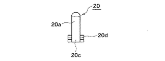
そして、これらの金属端子部材20では、図13乃至図15に示すように、一端部20a近傍に、側面視で、略L字状となるように屈曲されたL字状屈曲部20cが形成されている。
【0058】
また、この実施の形態1の金属端子部材20では、他端部20b近傍に、側面視で、クランク状となるように屈曲されたクランク状屈曲部20dが形成されていて、前記L字状屈曲部20c及びこのクランク状屈曲部20dが、図7乃至図10に示すように、前記蓋体17内で、長手方向両端縁部近傍に各々位置するように、この蓋体17を成型する際に、蓋体17の内部に予め埋設されるように構成されている。
【0059】
更に、この実施の形態1の金属端子部材20には、長手方向に直交する複数のセレーション20e…が形成されていて、更に、これらの金属端子部材20を長手方向に挿抜不能としている。
【0060】
また、これらのセレーション20eは、板状の金属端子部材20の上,下面で交互に略V字状の溝を形成することにより、この金属端子部材20の面内外方向の剛性が低下しないように構成されている。
【0061】
この金属端子部材20の他端部20bには、図2に示すように、前記燃料タンク1の外部に設けられている燃料計等に接続されるリード線12の端縁12aがコネクタソケット12bを介して接続されていて、このリード線12が、前記燃料タンク1のタンク蓋体2に挿通されて導出されることにより、燃料タンク1の外部に設けられている燃料計に、増幅又は補正された電気信号を送出するように構成されている。
【0062】
この実施の形態1では、前記金属端子部材20の他端部20bが、タンク蓋体2とは、反対側に向けて突設されることにより、燃料タンク1内で、前記リード線12…を上方に向けて折曲してから前記タンク蓋体2に挿通させて導出させている。
【0063】
更に、この実施の形態1では、前記蓋体17の裏面17a側に、回路基板18を収納する凹部17gが、凹状に形成されていると共に、この凹部17gの底面部からは、前記金属端子部材20の一端部20a…が、上方に向けて突設されていて、前記回路基板18の一端縁18b近傍に開口形成された端子孔18c…に各々嵌入されている。
【0064】
また、この凹部17gの前記他端部20b近傍に位置する他端縁18d近傍の底面部から上方に向けて突設された円筒状のボス部17gが、前記基板18の他端縁18d近傍に開口形成されたボス孔18eに嵌入されていて、基板18の長手方向両端縁18b,18dで、合計4カ所で固定されている。
【0065】
次に、この実施の形態1の液面検出装置の作用について説明する。
【0066】
このように構成された実施の形態1の液面検出装置では、図1に示すように、前記蓋体17の裏面17a側側面に、前記回路基板18が、予め装着される。
【0067】
この際、この回路基板18のホールIC素子10が固着された部品固着側側面18aを、目視しながら、前記蓋体17に装着出来、位置決め精度が良好である。
【0068】
この蓋体17を図中一点鎖線で示すように、前記ハウジング部材16の開口部16aに嵌合させると、前記ホールIC素子10は、前記マグネット9と対向する位置に装着される。
【0069】
このため、従来のように、前記回路基板18をハウジング部材16内の凹部に位置決めして固定する必要が無くなり、装着作業性が良好である。
【0070】
また、前記蓋体17が前記ハウジング部材16に嵌合される際には、前記開口部16aの周縁の内側面16h,16iに、外周面17e,17fが、内接して嵌着されて、前記第1段部16cと前記当接シール面部17cが対向することにより、前記溶着代16eの溶着によりシールされると共に、前記第2段部16dにフランジ部17dが当接してシールされて、水密となる。
【0071】
このように、前記内側面16h,16iに、外周面17e,17fが、内接して嵌着されるため、蓋体17の面延設方向での前記ハウジング部材16に対する嵌合の位置精度も良好である。
【0072】
また、予め前記回路基板18を、前記蓋体17に装着する際、前記金属端子部材20の一端部20a…が、前記回路基板18の一端縁18b近傍に開口形成された端子孔18c…に各々嵌入されると共に、前記他端部20b寄り他端縁近傍の底面部からは、円筒状のボス部17gが、上方へ向けて突設形成されていて、前記回路基板18の他端縁18d近傍に開口形成されたボス孔18eに嵌入されていて、基板18の長手方向両端縁18b,18dで、合計4カ所で固定されていることとなり、蓋体17に対する取付精度が良好である。
【0073】
しかも、この実施の形態1では、前記回路基板18の部品固着側側面18aに前記ホールIC素子10が固着されているので、蓋体17に回路基板18を取り付ける際に、このホールIC素子10を目視しながら位置合わせを行うことが出来る。このため、更に、このホールIC素子10の取付位置精度を良好なものとすることができる。
【0074】
このように、取付精度良く、前記蓋体17の裏面17aに回路基板18を装着しておけば、前記マグネット9に対するホールIC素子10の位置精度も良好なものとすることができる。
【0075】
また、前記金属端子部材20の一端部20a…を、前記端子孔18c…に各々嵌入してから、各一端部20a…の付け根部近傍を、この回路基板18のプリント配線等に各々ハンダ付けすれば、接続が完了するので、従来のように、リード線を回路基板のプリント配線にハンダ付けするものに比して、ハンダ付け作業性が良好であると共に、接続後の耐久性及び導電性も良好なものとすることができる。
【0076】
更に、従来のように余剰リード線を収納するスペースが不要となり、ハウジング部材16を小型化出来ると共に、レイアウト性も良好なものとすることができる。
【0077】
また、前記金属端子部材20が、他端部20bを前記密閉収納空間6の外部に導出して予め埋設されている。
【0078】
このため、別途、従来のようにリード線を抜け止めする抜け止め部材等が、不要となり、部品点数が減少するので、取付工数も減少し、装着作業性が良好である。
【0079】
また、前記金属端子部材20の他端部20bが、外部に導出されているので、前記密閉収納空間6の外部で、これらの他端部20b…と、前記リード線12の端縁12aに設けられたコネクタソケット12bを、下方から上方に向けて挿入することにより、ワンタッチで接続出来、結線が略終了する。
【0080】
従って、従来のように、前記密閉収納空間6内で、回路基板とリード線との結線を行わなければならないものに比して、作業性が良好である。
【0081】
前記金属端子部材20の他端部20bが、タンク蓋体2とは、反対側に向けて突設されることにより、燃料タンク1内で、前記リード線12…を上方に向けて折曲してから前記タンク蓋体2に挿通させて導出させている。
【0082】
このように、他端部20bが、タンク蓋体2とは、反対側に向けて突設されることにより、リード線12にタンク蓋体2方向に引かれる力が作用しても、抜けない。
【0083】
また、前記金属端子部材20…が、前記蓋体17内に位置する前記L字状屈曲部20c及びこのクランク状屈曲部20dを、各々略L字状及びクランク状に屈曲させた板状を呈しているので、これらのL字状屈曲部20c及びこのクランク状屈曲部20dが、抜け止めとなり、更に、前記ハウジング部材16から脱落しにくい。
【0084】
この実施の形態1では、前記金属端子部材20に、長手方向に直交する複数のセレーション20e…が形成されていて、更に、これらの金属端子部材20が長手方向に挿抜不能である。
【0085】
しかも、前記板状の金属端子部材20が、面内外方向に所定の剛性を有して前記蓋体17を補強するので、この蓋体17を前記ハウジング部材16に、嵌合させる際に、熱溶着を用いても変形しにくい。
【0086】
また、この板状の金属端子部材20によって、前記蓋体17の剛性が向上し、この蓋体17に予め装着される前記回路基板18に折れ曲がり方向の力が加わりにくく、前記ホールIC素子の電気的特性を安定させることができる。
【0087】
以上、図面を参照して、本発明の実施の形態1の液面検出装置を詳述してきたが、具体的な構成は、これらの実施の形態1に限らず、本発明の要旨を逸脱しない程度の設計的変更は、本発明に含まれる。
【0088】
例えば、前記実施の形態1では、前記凹部17gの前記他端部20b近傍に位置する他端縁18d近傍の底面部から上方に向けて突設された円筒状のボス部17gが、前記基板18の他端縁18d近傍に開口形成されたボス孔18eに嵌入されていて、基板18の長手方向両端縁18b,18dで、前記3本の金属端子部材20…の一端部20a…と共に、合計4カ所で固定されているが、特にこれに限らず、例えば、前記ボス部17g及びボス孔18eを省略すると共に、この実施の形態1のボス孔18e位置に、前記3本の金属端子部材20…のうち、中央の金属端子部材20の一端部20aを嵌入する端子孔18cを形成して、3カ所で、位置決め固定しても良く、前記蓋体17の裏面17aに、前記回路基板18が、前記ホールIC素子10が固着された部品固着側側面18aを、前記マグネット9方向に向けて、予め装着されているものであるならばよい。
【0089】
【発明の効果】
上述してきたように、請求項1記載のものでは、前記蓋体の密閉収納部側側面に予め、前記回路基板が、装着されているので、該蓋体を前記ハウジング部材に嵌合させると、前記磁気センサは、前記マグネットと対向する位置に装着される。
【0090】
このため、前記回路基板をハウジング部材内の凹部に位置決めして固定する必要が無くなり、装着作業性が良好である。
【0091】
また、前記蓋体が前記ハウジング部材に嵌合される際には、水密としなければならないので、前記ハウジング部材に対する嵌合の位置精度も良好である。
【0092】
従って、予め前記回路基板を取付精度良く、該蓋体の密閉収納部側側面に装着しておけば、前記マグネットに対する位置精度も良好なものとすることができる。
【0093】
そして、請求項2に記載されたものでは、前記電気配線が、他端部を前記密閉収納空間の外部に導出して予め埋設されている。
【0094】
このため、別途、リード線を抜け止めする抜け止め部材等が、不要となり、部品点数が減少するので、取付工数も減少し、装着作業性が良好である。
【0095】
また、前記電気配線の他端部が、外部に導出されているので、前記密閉収納空間の外部で、該他端部との結線を行うことができる。
【0096】
従って、従来のように、前記密閉収納空間内で、基板とリード線との結線を行わなければならないものに比して、作業性が良好であると共に、該密閉収納空間内に余剰リード線を収納する空間スペースを設ける必要も無く、前記ハウジング部材を小型化できる。
【0097】
更に、請求項3に記載されたものでは、前記電気配線が、前記蓋体内に位置する少なくとも一部を屈曲させた板状を呈しているので、屈曲部分が、抜け止めとなり、更に、前記ハウジング部材から脱落しにくい。
【0098】
しかも、前記板状の電気配線が、前記蓋体を補強するので、該蓋体を前記ハウジング部材に、嵌合させる際に、熱溶着を用いても変形しにくい。
【0099】
また、該板状の電気配線によって、前記蓋体の剛性が向上し、前記回路基板に折れ曲がり方向の力が加わりにくく、前記磁気センサの電気的特性を安定させることができる、という実用上有益な効果を発揮する。
【図面の簡単な説明】
【図1】本発明の実施の形態1の液面検出装置で、全体の構成を説明する分解斜視図である。
【図2】実施の形態1の液面検出装置で、燃料タンク内の構成を説明する正面図である。
【図3】実施の形態1の液面検出装置で、図2中A−A線に沿った位置での断面図である。
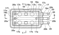
【図4】実施の形態1の液面検出装置で、ハウジング部材に装着される蓋体に予め回路基板を取り付けた構成を説明する上面図である。
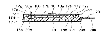
【図5】実施の形態1の液面検出装置で、ハウジング部材に装着される蓋体に予め回路基板を取り付けた構成を説明する図4中B−B線に沿った位置での断面図である。
【図6】実施の形態1の液面検出装置で、ハウジング部材に装着される蓋体に予め回路基板を取り付けた構成を説明する図4中C−C線に沿った位置での断面図である。
【図7】実施の形態1の液面検出装置で、ハウジング部材に装着される蓋体の構成を説明する側面図である。
【図8】実施の形態1の液面検出装置で、ハウジング部材に装着される蓋体の構成を説明する上面図である。
【図9】実施の形態1の液面検出装置で、ハウジング部材に装着される蓋体の構成を説明する図8中D−D線に沿った位置での断面図である。
【図10】実施の形態1の液面検出装置で、ハウジング部材に装着される蓋体の構成を説明する端子が突設された端縁側の正面図である。
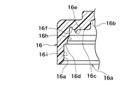
【図11】実施の形態1の液面検出装置で、ハウジング部材の構成を説明する側面図である。
【図12】実施の形態1の液面検出装置で、ハウジング部材の構成を説明する図11中E−E線に沿った位置での断面図である。
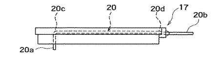
【図13】実施の形態1の液面検出装置で、金属端子部材の上面図である。
【図14】実施の形態1の液面検出装置で、金属端子部材の側面図である。
【図15】実施の形態1の液面検出装置で、金属端子部材の正面図である。
【図16】従来例の液面検出装置で、燃料タンク内の構成を説明する正面図である。
【図17】従来例の液面検出装置で、図16中F−F線に沿った位置での断面図である。
【符号の説明】
1 燃料タンク
6 密閉収納空間
7 アーム部
7a アーム部本体
9 マグネット
10 ホールIC素子
15 磁気式液面検出装置(液面検出装置)
16 ハウジング部材
17 蓋体
17a 裏面(密閉収納空間側側面)
18 回路基板
18a 部品固着側側面
20 金属端子部材(電気配線)
20c L字状屈曲部
20d クランク状屈曲部[0001]
TECHNICAL FIELD OF THE INVENTION
The present invention relates to a liquid level detection device used for displaying the remaining amount of fuel or the like stored in a liquid container such as a fuel tank, and mainly to a liquid level detection device mounted on a vehicle such as an automobile.
[0002]
[Prior art]
2. Description of the Related Art Conventionally, there has been known a liquid level detecting device for a vehicle mounted on a vehicle as shown in FIG. 16 or FIG.
[0003]
First, the structure will be described. In the magnetic liquid level detecting device 11 as the conventional liquid level detecting device, a stay extending from the fuel tank 1 of the tank lid 2 into the fuel tank 1 of the tank lid 2 is provided. The housing member 3 is fixed so as to be integrated with 2a.
[0004]
The housing member 3 has a recess 3b on one side and an opening 3a having an open end.
[0005]
The opening 3a is provided with a lid 4 fitted so as to be watertight with the periphery.
[0006]
By fitting the lid 4 inside the opening 3 a, the recess 3 b is formed together with the housing member 3 into a closed storage space 6 for storing the circuit board 5.
[0007]
An arm 7 having an arm body 7a extending into the fuel tank 1 is provided on the housing member 3 so as to be pivotally attached to the base end 7b so as to be rotatable. .
[0008]
A free end 7c of the arm body 7a is provided with a float member 8 which follows the vertical movement of the liquid level of the fuel in the fuel tank 1.
[0009]
Further, a magnet 9 for generating a magnetic field is provided on the arm portion 7 so as to be integral therewith, and is configured to rotate with the rotation of the arm main body 7a.
[0010]
Then, at a position facing the magnet 9 on the housing member 3 side, a magnetic field intensity that is changed by the movement of the magnet 9 accompanying the rotation of the arm main body 7a is detected on the substrate 5 so that the fuel is detected. A Hall IC element 10 is provided as a magnetic sensor that converts the position of the liquid surface into an electric signal.
[0011]
The Hall IC element 10 is connected via the circuit board 5 to a lead wire 12 arranged in the housing member 3, and the lead wire 12 is connected to the tank lid 2 of the fuel tank 1. , The amplified or corrected electric signal is transmitted to a fuel gauge provided outside the fuel tank 1.
[0012]
Next, the operation of the conventional liquid level detecting device will be described.
[0013]
In the conventional magnetic liquid level detection device 11, when the liquid level of the fuel in the fuel tank 1 moves up and down, the float member 8 moves up and down following the up and down movement of the liquid level, and the arm body 7a is rotated about the base end 7b as a rotation center.
[0014]
At this time, the magnet 9 provided so as to be integrated with the arm portion 7 also rotates with the rotation of the arm main body 7a, and changes the magnetic field around the housing member 3.
[0015]
The change in the magnetic field is converted into an electric signal by the Hall IC element 10 and sent out via the lead wire 12, and the liquid amount is displayed on a fuel gauge or the like provided outside the fuel tank 1. Is done.
[0016]
[Patent Document 1]
JP-A-2002-107205 (pages 2-3, FIGS. 1 and 3)
[0017]
[Problems to be solved by the invention]
However, in the conventional magnetic liquid level detecting device 1 for a vehicle, the circuit board 5 is mounted in the concave portion 3b of the housing member 3, and then the closed storage space 6 is made watertight by using the lid 4. It is closed to become.
[0018]
Therefore, it is necessary to position and fix the circuit board 5 at a position facing the magnet 9. As described above, when the circuit board 5 is mounted on the housing member 3 side, the mounting operation must be performed while viewing the circuit board 5 from the back surface side of the surface on which the Hall IC element 10 is mounted. It was difficult to improve the accuracy.
[0019]
Then, the lead wire 12 must be pulled out and connected to the circuit board 5 and soldering or the like must be performed. Thus, the workability of soldering is not good, and the excess lead wire remaining in the recess 3b is not good. 12 had to be accommodated in the closed storage space 6, so that it was difficult to say that the mounting workability was good.
[0020]
Further, when the lead wire 12 is pulled by a strong force, there is a possibility that the lead wire 12 may come off from the housing member 3. For this reason, it is necessary to perform the retaining process using the retaining member 13 and the like, and also in this respect, there is a problem that the number of parts and the number of mounting steps increase.
[0021]
SUMMARY OF THE INVENTION It is an object of the present invention to provide a liquid level detection device that can mount a magnetic sensor with good mounting workability and high positional accuracy without increasing the number of components.
[0022]
[Means for Solving the Problems]
The present invention has been made in view of such a problem. In the invention according to claim 1, a housing member fixed in the liquid container, and a circuit member fitted with the housing member, together with the housing member, A lid forming a sealed storage space for storing the substrate, an arm having an arm body pivotally attached to the housing member and extending into the liquid container, and a free end of the arm body And a float member that follows the vertical movement of the liquid surface in the liquid container, and a magnet that is provided in the arm portion and generates a magnetic field, and faces the magnet on the housing member side. The position is a liquid level detection device provided with a magnetic sensor that converts the position of the liquid level into an electric signal by detecting a magnetic field intensity that changes due to the movement of the magnet accompanying the rotation of the arm body. The circuit board is provided on the side surface of the lid on the side of the closed storage space, and the side surface on which the component is fixed to which the magnetic sensor is fixed is oriented in the direction of the magnet. Features the device.
[0023]
In the device according to claim 1 configured as described above, since the circuit board is previously mounted on the side surface of the lid body on the side of the closed storage portion, when the lid body is fitted to the housing member, The magnetic sensor is mounted at a position facing the magnet.
[0024]
For this reason, it is not necessary to position and fix the circuit board in the recess in the housing member, and the mounting workability is good.
[0025]
Further, when the lid is fitted to the housing member, it must be watertight, so that the positional accuracy of the fitting to the housing member is good.
[0026]
Therefore, if the circuit board is previously mounted on the side surface of the lid on the side of the closed storage portion with high mounting accuracy, the positional accuracy with respect to the magnet can be improved.
[0027]
According to the second aspect of the present invention, an electric wiring for connecting one end to the circuit board and leading the other end to the outside of the closed storage space is embedded in the lid in advance. A liquid level detecting device according to claim 1 is characterized.
[0028]
According to the second aspect of the present invention, the electric wiring is led out to the outside of the sealed storage space at the other end, and is embedded in advance.
[0029]
For this reason, a separate retaining member or the like for retaining the lead wire becomes unnecessary, and the number of components is reduced, so that the number of mounting steps is reduced and the mounting workability is good.
[0030]
Further, since the other end of the electric wiring is led out to the outside, the connection with the other end can be performed outside the sealed storage space.
[0031]
Therefore, as compared with the conventional case where the connection between the substrate and the lead wires must be performed in the closed storage space, the workability is good, and the extra lead wires are provided in the closed storage space. There is no need to provide a space for housing, and the housing member can be downsized.
[0032]
Further, in the liquid level detecting device according to the third aspect, the electric wiring has a plate shape, and at least a part located in the lid body is bent. .
[0033]
According to the third aspect of the present invention, since the electric wiring has a plate shape in which at least a part of the electric wiring is bent, the bent portion serves as a retaining member. It is hard to fall off from the housing member.
[0034]
In addition, since the plate-like electric wiring reinforces the lid, the lid is less likely to be deformed even when heat welding is used when fitting the lid to the housing member.
[0035]
Further, the rigidity of the lid is improved by the plate-shaped electric wiring, a force in a bending direction is hardly applied to the circuit board, and the electrical characteristics of the magnetic sensor can be stabilized.
[0036]
Embodiment 1 of the present invention
1 to 15 show a liquid level detecting device according to a first embodiment of the present invention.
[0037]
Note that the same or equivalent parts as those in the conventional example will be described with the same reference numerals.
[0038]
First, a description will be given of the configuration. In the magnetic liquid level detecting device as the liquid level detecting device according to the first embodiment, a fuel tank 1 as a liquid container is inserted into the fuel tank 1 from the inside of the tank lid 2. The housing member 16 is fixed so as to be integrated with the stay 2a extending toward the housing.
[0039]
The housing member 16 has a recess 16b on one side and an opening 16a having an open end.
[0040]
As shown in FIG. 12, the first step portion 16c and the second step portion 16d located outside the first step portion 16c have a stepped shape around the opening 16a of the first embodiment. Is formed.
[0041]
The first step portion 16c is provided with a welding margin 16e which is formed in a ring shape and is fused to the lid 17 by melting at the time of vibration welding, and further, a groove 16f is formed outside the welding margin 16e. Are formed in an annular recess.
[0042]
Further, the housing member 16 is provided with a lid 17 which is fitted to the periphery of the opening 16a so as to be watertight.
[0043]
The outer peripheral edge of the lid 17 is opposed to the first step portion 16c so as to come into contact with the lid 17 in the fitted state, and to be sealed by welding of the welding margin 16e. The flange portion 17d, which is located outside the contact seal surface portion 17c and faces the second step portion 16d, comes into contact with and seals in the fitted state of the lid 17 in a stepped manner. Have been.
[0044]
The outer peripheral surfaces 17e and 17f of the lid 17 are fitted in contact with the inner side surfaces 16h and 16i of the peripheral edge of the opening 16a, so that the position of the lid attaching position with respect to the housing member 16 is obtained. The precision is improved, and together with the housing member 16, the inside of the concave portion 16 b is made watertight, so that the closed storage space 6 for storing the circuit board 18 is formed.
[0045]
The housing member 16 is provided with an arm 7 having an arm main body 7a extending into the fuel tank 1 and pivotally attached to the base end 7b so as to be rotatable. .
[0046]
A free end 7c of the arm body 7a is provided with a float member 8 that follows the vertical movement of the liquid level S of the fuel F in the fuel tank 1.
[0047]
The arm 7 is provided with a bracket 19.
[0048]
The bracket 19 has a substantially disk shape and is provided with a magnet mounting portion 19a for fixing the magnet 9 for generating a magnetic field by the mounting claw portions 19b, 19b.
[0049]
As shown in FIG. 2, the magnet mounting portion 19a is locked at the base end thereof by a pair of locking claws 16g, 16g provided on the housing member 16 for preventing falling off. Rotation about the center 7b is allowed, and it is attached so as not to fall out of the housing member 16 in the axial extension direction of the base end portion 7b.
[0050]
The bracket 19 is provided integrally with the magnet mounting portion 19a, and is fixed to the arm main body 7a by claw portions 19d and 19e, so that the relative rotation of the magnet mounting portion 19a with respect to the arm main body 7a. A stopper 19b for preventing movement is provided.
[0051]
The magnet 9 is configured to rotate with the rotation of the arm body 7a.
[0052]
As shown in FIG. 4 to FIG. 6, the lid 17 is supported by disk pedestals 17b, 17b projecting from the back side 17a, which is the side surface of the closed storage space 6, at a predetermined distance. Then, the circuit board 18 is fixed.
[0053]
The circuit board 18 is mounted in advance with the component fixing side surface 18a to which the Hall IC element 10 as the magnetic sensor is fixed facing the magnet 9 so that the lid 17 is attached to the housing member. The Hall IC element 10 is configured to be located at a position facing the magnet 9 on the housing member 16 side in a state where the Hall IC element 10 is fitted to the housing 16.
[0054]
The Hall IC element 10 detects a magnetic field intensity that changes due to the movement of the magnet 9 accompanying the rotation of the arm main body 7 a on the substrate 5 at a position facing the magnet 9 on the housing member 16 side. Thus, the position of the liquid level of the fuel is converted into an electric signal.
[0055]
The Hall IC element 10 is connected via the circuit board 5 to one end portions 20a of three metal terminal members 20 which are embedded in the lid 17 in advance.
[0056]
Each of these metal terminal members 20 is formed of a conductive metal so as to have a substantially rod-like shape. The longitudinal direction of the metallic terminal members 20 is substantially the same as the length of the lid 17. The housing member 16 is buried across the housing member 16 such that the other end portion 20b located at the edge opposite to the one end portion 20a is led out into the fuel tank 1 outside the closed storage space 6. It protrudes downward from the lower part of the member.
[0057]
In these metal terminal members 20, as shown in FIGS. 13 to 15, an L-shaped bent portion 20c is formed near one end 20a so as to be substantially L-shaped when viewed from the side. ing.
[0058]
In the metal terminal member 20 according to the first embodiment, a crank-shaped bent portion 20d which is bent to have a crank shape in a side view is formed near the other end portion 20b, and the L-shaped bent portion is formed. When molding the lid 17 such that the portion 20c and the crank-shaped bent portion 20d are located in the vicinity of both longitudinal edges in the lid 17 as shown in FIGS. , And is buried in advance in the lid 17.
[0059]
Further, a plurality of serrations 20e which are orthogonal to the longitudinal direction are formed on the metal terminal member 20 of the first embodiment, and these metal terminal members 20 cannot be inserted or removed in the longitudinal direction.
[0060]
Further, the serrations 20e form substantially V-shaped grooves alternately on the upper and lower surfaces of the plate-shaped metal terminal member 20 so that the rigidity of the metal terminal member 20 in the in-plane and out-of-plane directions is not reduced. It is configured.
[0061]
As shown in FIG. 2, an end 12a of a lead wire 12 connected to a fuel gauge or the like provided outside the fuel tank 1 is connected to a connector socket 12b at the other end 20b of the metal terminal member 20. When the lead wire 12 is inserted through the tank lid 2 of the fuel tank 1 and led out, the lead wire 12 is amplified or corrected by a fuel gauge provided outside the fuel tank 1. It is configured to transmit an electric signal.
[0062]
In the first embodiment, the other end portion 20b of the metal terminal member 20 is provided so as to protrude toward the side opposite to the tank lid 2, so that the lead wires 12 are formed in the fuel tank 1. After being bent upward, it is inserted through the tank lid 2 and led out.
[0063]
Further, in the first embodiment, a concave portion 17g for accommodating the circuit board 18 is formed in a concave shape on the back surface 17a side of the lid 17 and the metal terminal member is formed from the bottom portion of the concave portion 17g. 20 have one end portions 20a projecting upward, and are fitted into terminal holes 18c formed in the vicinity of one end edge 18b of the circuit board 18, respectively.
[0064]
A cylindrical boss 17g projecting upward from a bottom surface near the other end 18d located near the other end 20b of the concave portion 17g is provided near the other end 18d of the substrate 18. It is fitted in the boss hole 18e formed with an opening, and is fixed at a total of four places at both ends 18b and 18d in the longitudinal direction of the substrate 18.
[0065]
Next, the operation of the liquid level detecting device according to the first embodiment will be described.
[0066]
In the liquid level detecting device according to the first embodiment configured as described above, the circuit board 18 is mounted in advance on the side surface on the back surface 17a side of the lid 17 as shown in FIG.
[0067]
At this time, the component fixing side surface 18a of the circuit board 18 to which the Hall IC element 10 is fixed can be attached to the lid 17 while visually observing, and the positioning accuracy is good.
[0068]
When the lid 17 is fitted into the opening 16a of the housing member 16 as shown by a dashed line in the figure, the Hall IC element 10 is mounted at a position facing the magnet 9.
[0069]
For this reason, unlike the related art, it is not necessary to position and fix the circuit board 18 in the concave portion in the housing member 16, and the mounting workability is good.
[0070]
When the lid 17 is fitted to the housing member 16, outer peripheral surfaces 17e and 17f are fitted to inner peripheral surfaces 16h and 16i of the periphery of the opening 16a in an inscribed manner. When the first step 16c and the contact seal face 17c face each other, the seal is formed by welding of the welding allowance 16e, and the second step 16d is sealed by contacting the flange 17d with the second step 16d. Become.
[0071]
As described above, since the outer peripheral surfaces 17e and 17f are inscribed and fitted to the inner side surfaces 16h and 16i, the positional accuracy of the fitting to the housing member 16 in the surface extending direction of the lid 17 is also good. It is.
[0072]
When the circuit board 18 is attached to the lid 17 in advance, one end portions 20a of the metal terminal members 20 are respectively inserted into terminal holes 18c formed in the vicinity of one end edge 18b of the circuit board 18. At the same time, a cylindrical boss 17g is formed so as to protrude upward from the bottom surface near the other end 20b near the other end 20b and near the other end 18d of the circuit board 18. The boss hole 18e formed in the opening 18 is fixed at four places at both ends 18b and 18d in the longitudinal direction of the board 18 in total, so that the mounting accuracy with respect to the lid 17 is good.
[0073]
Moreover, in the first embodiment, since the Hall IC element 10 is fixed to the side surface 18a on the component fixing side of the circuit board 18, when the circuit board 18 is attached to the lid 17, the Hall IC element 10 is Positioning can be performed visually. Therefore, the mounting position accuracy of the Hall IC element 10 can be further improved.
[0074]
In this way, if the circuit board 18 is mounted on the back surface 17a of the lid 17 with high mounting accuracy, the positional accuracy of the Hall IC element 10 with respect to the magnet 9 can be improved.
[0075]
After the one end portions 20a of the metal terminal members 20 are respectively fitted into the terminal holes 18c, the vicinity of the root of each one end portion 20a is soldered to a printed wiring or the like of the circuit board 18. For example, since the connection is completed, the soldering workability is better and the durability and conductivity after connection are better than those in the conventional case where the lead wires are soldered to the printed wiring on the circuit board. It can be good.
[0076]
Further, a space for accommodating excess lead wires as in the related art is not required, so that the housing member 16 can be reduced in size and the layout can be improved.
[0077]
In addition, the metal terminal member 20 has the other end portion 20b led out of the sealed storage space 6 and is embedded in advance.
[0078]
For this reason, a separate retaining member for retaining the lead wire as in the related art becomes unnecessary, and the number of components is reduced. Therefore, the number of mounting steps is reduced, and the mounting workability is good.
[0079]
Since the other end portion 20b of the metal terminal member 20 is led out to the outside, the other end portion 20b... And the edge 12a of the lead wire 12 are provided outside the closed storage space 6. The inserted connector socket 12b is inserted upward from below so that the connection can be made with one touch and the connection is substantially completed.
[0080]
Therefore, the workability is better than that in the related art, in which the connection between the circuit board and the lead wires must be performed in the closed storage space 6.
[0081]
The other end portion 20b of the metal terminal member 20 is protruded toward the side opposite to the tank lid 2, so that the lead wires 12 are bent upward in the fuel tank 1. After that, it is inserted through the tank lid 2 and led out.
[0082]
In this manner, the other end portion 20b is protruded toward the side opposite to the tank lid 2, so that the lead wire 12 does not come off even if a force is applied to the lead wire 12 in the direction of the tank lid 2. .
[0083]
The metal terminal members 20 have a plate shape obtained by bending the L-shaped bent portion 20c and the crank-shaped bent portion 20d located in the lid 17 into a substantially L-shaped and a crank-shaped, respectively. As a result, the L-shaped bent portion 20c and the crank-shaped bent portion 20d serve as stoppers and are less likely to fall off the housing member 16.
[0084]
In the first embodiment, a plurality of serrations 20e which are orthogonal to the longitudinal direction are formed on the metal terminal member 20, and further, these metal terminal members 20 cannot be inserted and removed in the longitudinal direction.
[0085]
In addition, since the plate-shaped metal terminal member 20 has a predetermined rigidity in the in-plane and out-of-plane directions and reinforces the lid 17, when the lid 17 is fitted to the housing member 16, heat is applied. It is difficult to deform even if welding is used.
[0086]
In addition, the rigidity of the lid 17 is improved by the plate-shaped metal terminal member 20, and a force in a bending direction is less likely to be applied to the circuit board 18 previously mounted on the lid 17, so that the electric power of the Hall IC element is reduced. Characteristic can be stabilized.
[0087]
The liquid level detecting device according to the first embodiment of the present invention has been described above in detail with reference to the drawings. However, the specific configuration is not limited to the first embodiment and does not depart from the gist of the present invention. A degree of design change is included in the present invention.
[0088]
For example, in the first embodiment, the cylindrical boss 17g protruding upward from the bottom surface near the other end 18d located near the other end 20b of the recess 17g is provided with the substrate 18. Of the three metal terminal members 20... Together with one end 20 a of the three metal terminal members 20. However, the present invention is not particularly limited thereto. For example, the boss 17g and the boss hole 18e are omitted, and the three metal terminal members 20 are located at the boss hole 18e of the first embodiment. Among them, a terminal hole 18c into which the one end portion 20a of the central metal terminal member 20 is fitted may be formed and positioned and fixed at three places, and the circuit board 18 Hall IC Parts sticking side surface 18a of the child 10 is secured, toward the magnet 9 direction may if those that are previously mounted.
[0089]
【The invention's effect】
As described above, in the device according to claim 1, since the circuit board is mounted in advance on the side surface of the lid body on the side of the closed storage section, when the lid body is fitted to the housing member, The magnetic sensor is mounted at a position facing the magnet.
[0090]
For this reason, it is not necessary to position and fix the circuit board in the recess in the housing member, and the mounting workability is good.
[0091]
Further, when the lid is fitted to the housing member, it must be watertight, so that the positional accuracy of the fitting to the housing member is good.
[0092]
Therefore, if the circuit board is previously mounted on the side surface of the lid on the side of the closed storage portion with high mounting accuracy, the positional accuracy with respect to the magnet can be improved.
[0093]
According to the second aspect of the present invention, the electric wiring is embedded in advance by leading the other end to the outside of the closed storage space.
[0094]
For this reason, a separate retaining member or the like for retaining the lead wire becomes unnecessary, and the number of components is reduced, so that the number of mounting steps is reduced and the mounting workability is good.
[0095]
Further, since the other end of the electric wiring is led out to the outside, the connection with the other end can be performed outside the sealed storage space.
[0096]
Therefore, as compared with the conventional case where the connection between the substrate and the lead wires must be performed in the closed storage space, the workability is good, and the extra lead wires are provided in the closed storage space. There is no need to provide a space for housing, and the housing member can be downsized.
[0097]
Furthermore, according to the third aspect of the present invention, since the electric wiring has a plate shape in which at least a part located in the lid is bent, the bent portion serves as a stopper, and further, the housing It is hard to fall off the member.
[0098]
In addition, since the plate-like electric wiring reinforces the lid, the lid is less likely to be deformed even when heat welding is used when fitting the lid to the housing member.
[0099]
In addition, the plate-shaped electric wiring improves the rigidity of the lid, hardly applies a force in the bending direction to the circuit board, and stabilizes the electrical characteristics of the magnetic sensor. It is effective.
[Brief description of the drawings]
FIG. 1 is an exploded perspective view illustrating an overall configuration of a liquid level detecting device according to a first embodiment of the present invention.
FIG. 2 is a front view illustrating a configuration inside a fuel tank in the liquid level detection device according to the first embodiment.
FIG. 3 is a cross-sectional view of the liquid level detecting device according to the first embodiment, taken along a line AA in FIG. 2;
FIG. 4 is a top view illustrating a configuration in which a circuit board is previously attached to a lid attached to a housing member in the liquid level detection device according to the first embodiment.
FIG. 5 is a cross-sectional view taken along a line BB in FIG. 4 illustrating a configuration in which a circuit board is previously attached to a lid mounted on a housing member in the liquid level detection device according to the first embodiment. is there.
FIG. 6 is a cross-sectional view taken along a line CC in FIG. 4 illustrating a configuration in which a circuit board is previously attached to a lid attached to a housing member in the liquid level detection device according to the first embodiment. is there.
FIG. 7 is a side view illustrating a configuration of a lid mounted on a housing member in the liquid level detection device according to the first embodiment.
FIG. 8 is a top view illustrating a configuration of a lid mounted on a housing member in the liquid level detection device according to the first embodiment.
FIG. 9 is a cross-sectional view taken along a line DD in FIG. 8 illustrating a configuration of a lid attached to a housing member in the liquid level detection device according to the first embodiment.
FIG. 10 is a front view of the liquid level detecting device according to the first embodiment on the side of an edge where terminals for explaining a configuration of a lid attached to a housing member are protruded.
FIG. 11 is a side view illustrating a configuration of a housing member in the liquid level detection device according to the first embodiment.
FIG. 12 is a cross-sectional view illustrating a configuration of a housing member in the liquid level detection device according to the first embodiment, taken along a line EE in FIG. 11;
FIG. 13 is a top view of a metal terminal member in the liquid level detecting device according to the first embodiment.
FIG. 14 is a side view of a metal terminal member in the liquid level detecting device according to the first embodiment.
FIG. 15 is a front view of a metal terminal member in the liquid level detecting device according to the first embodiment.
FIG. 16 is a front view illustrating a configuration inside a fuel tank in a conventional liquid level detection device.
FIG. 17 is a cross-sectional view of a conventional liquid level detecting device taken along a line FF in FIG. 16;
[Explanation of symbols]
1 fuel tank
6 closed storage space
7 Arm part
7a Arm part body
9 magnets
10 Hall IC device
15 Magnetic liquid level detector (liquid level detector)
16 Housing member
17 Lid
17a back side (closed storage space side side)
18 Circuit board
18a Side surface where the parts are fixed
20 Metal terminal members (electrical wiring)
20c L-shaped bent part
20d crank-shaped bent part