【0001】
【発明の属する技術分野】
本発明は、引戸用ランナを走行させるレール端部に配設され、引戸を閉止する際の慣性力を減殺するとともに、跳ね返りを防止するための引戸用制動装置に関する。
【0002】
【従来の技術】
従来より、引戸においては、軽い力で開閉操作が行えるようにランナ(ローラ装置)を設けたものが多く提供されている。しかし、引戸を勢いよく閉めると、衝突音が発生したり、戸枠から跳ね返って隙間ができたりすることがあるため、この衝突音や跳ね返りを防止するためにレールの端部に引戸の慣性力を減殺させる制動装置を設けることが行われている。
【0003】
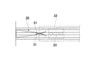
例えば、下記特許文献1においては、図8に示されるような引戸用制動装置30が提案されている。この引戸用制動装置30は、バネ作用を有する左右一対の制動片31,31(板バネ部材)により係合溝が形成された部材であって、レール端部に配設され、前記引戸32に設けられた凸状部材33が前記係合溝に嵌入する際にバネ作用により引戸32の慣性力を減殺するようになっている。このような制動装置は、通常「引戸用キャッチ」と呼ばれているものである。
【0004】
一方、例えば収納棚、食器棚、陳列棚等の収納家具等の引戸においては、引戸を閉止位置近傍まで移動させると、引戸に閉方向の付勢力が加わり、閉止位置まで誘導して隙間を空けることなく完全な閉状態とする戸締り装置(自閉装置)が設けられることがある。このような戸締り装置としては、例えば下記特許文献2などを挙げることができる。
【0005】
【特許文献1】
登録実用新案第3006645号公報
【特許文献2】
特開2002−339649号公報
【0006】
【発明が解決しようとする課題】
前記引戸用制動装置30により、引戸32の衝突音や跳ね返り等が防止できるようになるが、戸締まりをアシストする機能までをも有するものではない。
【0007】
一方、引戸の戸締り装置は構造が複雑であるとともに、戸枠と合わせた設計を必要とし、一般的な引戸に組込むことは困難であるとともに、価格が高価であるなどの問題があった。
【0008】
そこで本発明の主たる課題は、キャッチ式の引戸用制動装置に対して、戸締まりのアシスト機能を付加することにある。
【0009】
【課題を解決するための手段】
前記課題を解決するための請求項1に係る本発明として、開閉方向にバネ作用を有する左右一対の制動片によりピン係合溝が形成されるとともに、引戸用ランナを走行させるレール端部に配設され、前記引戸用ランナに設けられたピン部材が前記ピン係合溝に嵌入する際にバネ作用により引戸の慣性力を減殺するための引戸用制動装置において、
前記ピン係合溝は、奥端部の溝幅を前記ピン部材の径とほぼ一致させ、ピン係合溝の中間に形成された最狭部から前記奥端部までテーパー状に漸次溝幅を拡大させるように形成してあることを特徴とする引戸用制動装置が提供される。
【0010】
上記請求項1記載の本発明においては、ピン係合溝の溝形状に関し、奥端部の溝幅を前記ピン部材の径とほぼ一致させ、ピン係合溝の中間に形成された最狭部から前記奥端部までテーパー状に漸次溝幅を拡大させるように形成した。従って、前記制動片からピン部材に作用する力の奥端部方向分力により前記ピン部材が自然に奥端部側へ誘導され、奥端部位置にきっちりと停止するようになるため、引戸を閉め残しなく完全に閉止できるようになる。
【0011】
請求項2に係る本発明として、前記最狭部から前記奥端部までのテーパー長は少なくとも20mm以上としてある請求項1記載の引戸用制動装置が提供される。
【0012】
請求項3に係る本発明として、前記左右一対の制動片の先端には、相反する外側方向に突出する係合突起が夫々設けられ、これら係合突起をレールに形成された係合溝に係合させることにより前記制動片の横ブレを防止してある請求項1,2いずれかに記載の引戸用制動装置が提供される。前記制動片は張出長が長い部材であるため、ピン部材が接触した際に、左右方向に横ブレすることが予想される。従って、前記制動片の先端に係合突起を設け、これをレールの係合溝に係合させることにより横ブレを無くすことが可能となる。
【0013】
請求項4に係る本発明として、前記ピン係合溝は最狭部から開口部まで漸次溝幅を拡大させてある請求項1〜3いずれかに記載の引戸用制動装置が提供される。ピン係合溝内にピン部材が円滑に導入されるように、開口部は最狭部から漸次拡大させるようにするのが望ましい。
【0014】
【発明の実施の形態】
以下、本発明の実施の形態について図面を参照しながら詳述する。
【0015】
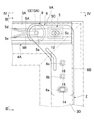
図1は、本発明が適用された収納棚の全体斜視図であり、図2は本発明に係る引戸用制動装置取付け部分の正面図、図3はそのIII−III線矢視図、図4は図2のIV−IV線矢視図である。
【0016】
図1に示されるように、引戸2は、例えばアルミ等の金属形材からなる上框3A、下框3B及び縦框3C、3Dによって構成されたフレーム枠3内にガラス等のパネル7が嵌め込まれたものであり、前記引戸2のフレーム枠3の裏面側にはランナ装置6(以下、単にランナという。)が取り付けられている。
【0017】
一方、収納棚1は、上板1Aの端面と下板1Bの端面とにそれぞれ水平方向に沿って上レール4A,下レール4Bが設けられ、収納棚1の開口幅約1/3幅とされる2枚の引戸2,2が前記上レール4Aおよび下レール4Bを走行ガイドとして案内される前記ランナ6により開閉自在に設けられている。なお、図示の例では、引戸2が2枚設けられた両開きタイプとしたが、収納棚1の開口幅約1/2とされる引戸2が1枚のみ設けられた片開きタイプであってもよい。
【0018】
前記ランナ6は、図2および図3に示されるように、上框3Aと縦框3Dとが交差する隅部において、一辺側6Aを上框3A方向に配向するとともに、他辺側6Bを縦框3D方向に沿って配向した状態で取り付けられている。前記一辺側6Aには、先端側にローラ部材9が支軸13によって支持されているとともに、前記支軸13を上レール4A側へ突出させ、引戸用制動装置5に対して係脱可能とされるピン部材13Aを一体的に兼用するようにしている。
【0019】
一方、前記他辺側6Bには、先端側より、水平方向に長孔の仮固定用ネジ取付孔6aと、丸孔状の2つの本固定用ネジ取付孔6b、揺動軸用ネジ孔6cが形成されており、先ず揺動軸用ネジ孔6cにネジ16を螺入し、ランナ6を揺動可能な状態で取り付けるとともに、長孔の仮固定用ネジ取付孔6aに仮止めネジ14を螺入しておくけれども締結せず、ランナ6を揺動可能な状態としておく。その後、ローラ部材9を上レール4A位置に位置決めした後、仮止めネジ14を螺入してその位置状態で仮止めし、次いで本固定用ネジ取付孔6bに本固定用ネジ15を螺入して堅固に固定を図るようにする。
【0020】
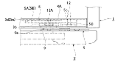
前記ローラ部材9は、図3に示されるように、実際に上レール4Aを走行する走行ローラ部9aと、前記走行ローラ部9aの外側に隣接して一体的に形成された若干大径の外れ止めローラ部9bとからなり、一方前記上レール4Aは、断面略溝型形状を成し、部材長手方向に沿って適宜の間隔で形成されたネジ取付孔4b、4b…から螺入された固定ネジ11,11…によって上板1Aの端面および下板1Bの端面にそれぞれ固定されている。また、ローラ走行部となる下フランジには凹溝4aが形成され、この凹溝4aの外側壁部の上面を前記走行ローラ部9aが走行し、前記凹溝4a内に前記外れ止めローラ部9bが嵌合するようになっており、引戸2が容易に外れないように保持されている。前記上レール4Aの端部に対し、本発明に係る引戸用制動装置5が配置されている。
【0021】
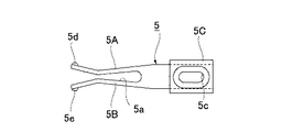
前記引戸用制動装置5は、詳細には図5に示されるように、開閉方向にバネ作用を有する左右一対の制動片5A、5Bによりピン係合溝5aが形成された部材であり、他端側にビス孔5cを有する取付用ベース板5Cが一体的に設けられ、図4に示されるように、固定ビス12により上レール4Aの端部に固定されるようになっている。そして、前記ランナ6に設けられたピン部材13Aが前記ピン係合溝5aに嵌入する際に、バネ作用により引戸2の慣性力を減殺し、戸閉止時の衝突音や跳ね返りを防止するようになっている。
【0022】
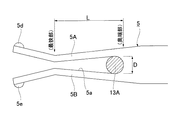
前記引戸用制動装置5について、図6に基づいて更に詳述すると、前記ピン係合溝5aは、奥端部の溝幅Dを前記ピン部材13Aの径とほぼ一致させ、ピン係合溝5aの中間に形成された最狭部から前記奥端部までテーパー状に漸次溝幅を拡大させるように形成している。この場合、前記最狭部から前記奥端部までテーパー長Lは少なくとも20mm以上、好ましくは30mm以上とするのが望ましい。なお、前記ピン係合溝5aの開口側では、前記最狭部から開口部まで漸次溝幅を拡大させ、ピン13Aが円滑にピン係合溝5a内に導かれるようにしてある。
【0023】
前記引戸2を閉め、ランナ6のピン部材13Aが前記制動装置5のピン係合溝5a内に入り込み前記最狭部を越えると、図7に示されるように、ピン部材13Aの両側から前記制動片5A、5Bによって挟閉方向に力が加わるようになる。この挟閉方向の力Fは鉛直方向成分FYと、奥端部方向成分FXとに分解することができ、前記奥端部方向成分FXの力にアシストされながらピン部材13Aは自然にピン係合溝5aの奥端部側に誘導され、引戸2の完全な閉止位置となる奥端部位置まで至り、引戸2が閉め残しなく完全に閉止されるようになる。
【0024】
ところで、前記制動片5A、5Bの先端部には、相反する外側方向に突出する係合突起5d、5eが夫々設けられ、図3に示されるように、これら係合突起5d、5eを上レール4Aに形成された係合溝4cに係合させることにより前記制動片5A、5Bの横ブレが防止されるようになっている。
【0025】
以上、引戸2の上端右側に配置されるランナ6及び引戸用制動装置5について説明を行ったが、引戸用制動装置5は下端側についても対称配置で同様に取り付けることが可能である。また、収納棚2の左側に設けられる引戸2についても同様である。
【0026】
(他の実施形態例)
(1)上記実施形態例では収納棚1の開口に設けられる引戸2に対して本発明を適用した例について詳述したが、本発明は引戸一般に適用が可能である。
【0027】
【発明の効果】
以上詳説のとおり本発明によれば、キャッチ式の引戸用制動装置に対して、戸締まりのアシスト機能を付加することができ、引戸を閉め残しなくきっちりと閉止できるようになる。
【図面の簡単な説明】
【図1】本発明が適用された収納棚の全体斜視図である。
【図2】本発明に係る引戸用制動装置5の取付け状態を示す正面図である。
【図3】そのII−II線矢視図である。
【図4】図2のIV−IV線矢視図である。
【図5】引戸用制動装置5の正面図である。
【図6】引戸用制動装置5の要部拡大図である。
【図7】引戸用制動装置5によるアシスト機能の説明図である。
【図8】従来に係る引戸用制動装置の正面図である。
【符号の説明】
1…収納棚、2…引戸、3…フレーム枠、3A…上框、3B…下框、3C・3D…縦框、4A…上レール、4B…下レール、5…引戸用制動装置、5A・5B…制動片、5a…ピン係合溝、5d・5e…係合突起、6…ランナ、7…パネル、9…ローラ部材、13A…ピン部材[0001]
TECHNICAL FIELD OF THE INVENTION
The present invention relates to a sliding door braking device that is disposed at an end of a rail on which a sliding door runner travels to reduce inertial force when the sliding door is closed and to prevent rebound.
[0002]
[Prior art]
2. Description of the Related Art Conventionally, many sliding doors are provided with a runner (roller device) so that an opening and closing operation can be performed with a light force. However, if the sliding door is closed vigorously, a collision sound may be generated or a gap may be created by rebounding from the door frame.In order to prevent the collision sound and the rebound, the sliding door has an inertial force at the end of the rail. It has been practiced to provide a braking device for reducing the pressure.
[0003]
For example, Patent Document 1 below proposes a sliding door braking device 30 as shown in FIG. The sliding door braking device 30 is a member in which an engagement groove is formed by a pair of left and right braking pieces 31, 31 (leaf spring members) having a spring action, and is disposed at an end of a rail. When the provided convex member 33 is fitted into the engagement groove, the inertia force of the sliding door 32 is reduced by a spring action. Such a braking device is usually called a "sliding door catch".
[0004]
On the other hand, in sliding doors such as storage furniture such as storage shelves, cupboards and display shelves, when the sliding door is moved to near the closed position, a biasing force is applied to the sliding door in the closing direction to guide the sliding door to the closed position and leave a gap. There is a case where a door closing device (self-closing device) for completely closing the door is provided. As such a door-locking device, for example, Patent Literature 2 below can be cited.
[0005]
[Patent Document 1]
Registered Utility Model No. 3006453 [Patent Document 2]
JP-A-2002-339649
[Problems to be solved by the invention]
Although the sliding door braking device 30 can prevent the collision sound and rebound of the sliding door 32, it does not have the function of assisting the door closing.
[0007]
On the other hand, the door locking device of a sliding door has a complicated structure, requires a design in combination with a door frame, is difficult to incorporate into a general sliding door, and has problems such as being expensive.
[0008]
Therefore, a main object of the present invention is to add a door-closing assist function to a catch-type sliding door braking device.
[0009]
[Means for Solving the Problems]
According to a first aspect of the present invention, a pin engagement groove is formed by a pair of left and right braking pieces having a spring action in an opening and closing direction, and the pin engagement groove is formed at a rail end for running a sliding door runner. In the braking device for a sliding door for reducing the inertial force of the sliding door by a spring action when a pin member provided on the runner for the sliding door is fitted into the pin engagement groove,
The pin engagement groove has a groove width at a rear end portion substantially equal to a diameter of the pin member, and gradually increases a groove width in a tapered shape from a narrowest portion formed in the middle of the pin engagement groove to the rear end portion. A sliding door braking device is provided that is configured to be enlarged.
[0010]
According to the first aspect of the present invention, with regard to the groove shape of the pin engagement groove, the groove width at the rear end portion is made substantially equal to the diameter of the pin member, and the narrowest portion formed in the middle of the pin engagement groove The groove width was gradually increased in a tapered shape from the end to the back end. Therefore, the pin member is naturally guided to the back end side by the back end direction component force of the force acting on the pin member from the braking piece, and the pin member comes to stop exactly at the back end position. It will be possible to completely close without closing.
[0011]
According to the second aspect of the present invention, there is provided the sliding door braking device according to the first aspect, wherein a taper length from the narrowest portion to the far end is at least 20 mm or more.
[0012]
According to a third aspect of the present invention, opposite ends of the pair of left and right braking pieces are provided with engaging projections protruding in opposite directions, and these engaging projections are engaged with engaging grooves formed in the rail. The sliding device for a sliding door according to any one of claims 1 and 2, wherein the brake pieces are prevented from being laterally shaken by being combined. Since the brake piece is a member having a long overhang, it is expected that the brake piece laterally shakes in the left-right direction when the pin member comes into contact. Therefore, it is possible to eliminate lateral blur by providing an engagement projection at the tip of the braking piece and engaging it with the engagement groove of the rail.
[0013]
According to a fourth aspect of the present invention, there is provided the braking device for a sliding door according to any one of the first to third aspects, wherein the pin engagement groove has a groove width gradually increased from a narrowest portion to an opening. It is desirable that the opening be gradually enlarged from the narrowest portion so that the pin member is smoothly introduced into the pin engagement groove.
[0014]
BEST MODE FOR CARRYING OUT THE INVENTION
Hereinafter, embodiments of the present invention will be described in detail with reference to the drawings.
[0015]
FIG. 1 is an overall perspective view of a storage shelf to which the present invention is applied, FIG. 2 is a front view of a mounting portion of a sliding door braking device according to the present invention, FIG. 3 is a view taken along line III-III of FIG. FIG. 4 is a view taken along line IV-IV in FIG. 2.
[0016]
As shown in FIG. 1, the sliding door 2 has a panel 7 made of glass or the like fitted in a frame 3 composed of an upper frame 3A, a lower frame 3B, and vertical frames 3C and 3D made of a metal material such as aluminum. A runner device 6 (hereinafter simply referred to as a runner) is attached to the back side of the frame 3 of the sliding door 2.
[0017]
On the other hand, the storage shelf 1 is provided with upper rails 4A and lower rails 4B along the horizontal direction on the end surface of the upper plate 1A and the end surface of the lower plate 1B, respectively. Two sliding doors 2 are provided to be openable and closable by the runner 6 guided by the upper rail 4A and the lower rail 4B as a traveling guide. In the illustrated example, the sliding door 2 is a double-opening type provided with two sliding doors. However, a single-opening type provided with only one sliding door 2 having an opening width of the storage shelf 1 of about 1/2 is provided. Good.
[0018]
As shown in FIGS. 2 and 3, the runner 6 has one side 6A oriented in the direction of the upper frame 3A and the other side 6B vertically aligned at a corner where the upper frame 3A and the vertical frame 3D intersect. It is attached in a state oriented along the direction of the frame 3D. On one side 6A, a roller member 9 is supported by a support shaft 13 at the tip end, and the support shaft 13 is protruded toward the upper rail 4A so as to be disengageable from the sliding door braking device 5. The pin member 13A is also used integrally.
[0019]
On the other hand, on the other side 6B, from the tip end side, a temporary fixing screw mounting hole 6a having a long hole in the horizontal direction, two round fixing screw mounting holes 6b, and a swing shaft screw hole 6c are formed. First, a screw 16 is screwed into the screw hole 6c for the swing shaft, the runner 6 is attached in a swingable state, and the temporary fixing screw 14 is inserted into the long temporary fixing screw mounting hole 6a. Although it is screwed in, but not fastened, the runner 6 is set in a swingable state. Then, after positioning the roller member 9 at the position of the upper rail 4A, the temporary fixing screw 14 is screwed in and temporarily fixed in the position, and then the final fixing screw 15 is screwed into the final fixing screw mounting hole 6b. And firmly fix it.
[0020]
As shown in FIG. 3, the roller member 9 has a traveling roller portion 9a that actually travels on the upper rail 4A and a slightly large-diameter disengagement formed integrally adjacent to the outside of the traveling roller portion 9a. The upper rail 4A has a substantially groove-shaped cross section, and is screwed into screw mounting holes 4b, 4b,... Formed at appropriate intervals along the longitudinal direction of the member. Are fixed to the end surface of the upper plate 1A and the end surface of the lower plate 1B by screws 11, 11. A concave groove 4a is formed in a lower flange serving as a roller traveling portion, and the traveling roller portion 9a travels on the upper surface of an outer wall portion of the concave groove 4a, and the slip-off preventing roller portion 9b is inserted in the concave groove 4a. Are fitted so that the sliding door 2 is not easily detached. A sliding door braking device 5 according to the present invention is disposed at an end of the upper rail 4A.
[0021]
As shown in detail in FIG. 5, the sliding door braking device 5 is a member in which a pin engagement groove 5a is formed by a pair of left and right braking pieces 5A and 5B having a spring action in the opening and closing directions. A mounting base plate 5C having a screw hole 5c on the side is integrally provided, and is fixed to an end of the upper rail 4A by a fixing screw 12, as shown in FIG. Then, when the pin member 13A provided on the runner 6 is fitted into the pin engagement groove 5a, the inertia force of the sliding door 2 is reduced by a spring action so as to prevent a collision sound and a rebound when the door is closed. Has become.
[0022]
The sliding door braking device 5 will be described in further detail with reference to FIG. 6. The pin engaging groove 5 a makes the groove width D at the rear end substantially coincide with the diameter of the pin member 13 </ b> A. Is formed so as to gradually increase the groove width in a tapered shape from the narrowest portion formed in the middle of the groove to the far end. In this case, it is desirable that the taper length L from the narrowest portion to the far end is at least 20 mm or more, preferably 30 mm or more. On the opening side of the pin engaging groove 5a, the groove width is gradually increased from the narrowest portion to the opening so that the pin 13A is smoothly guided into the pin engaging groove 5a.
[0023]
When the sliding door 2 is closed and the pin member 13A of the runner 6 enters the pin engagement groove 5a of the braking device 5 and passes over the narrowest portion, the braking is performed from both sides of the pin member 13A as shown in FIG. A force is applied in the closing direction by the pieces 5A and 5B. The force F of the Kyo閉direction and the vertical component F Y, can be decomposed into octane unit direction component F X, the pin member 13A is naturally while being assisted force of the inner end portion direction component F X The sliding door 2 is guided to the far end side of the pin engaging groove 5a and reaches the far end position where the sliding door 2 is completely closed, so that the sliding door 2 is completely closed without being left closed.
[0024]
By the way, opposite ends of the braking pieces 5A, 5B are provided with engaging projections 5d, 5e projecting in opposite directions, respectively, and as shown in FIG. By engaging with the engagement groove 4c formed in 4A, the lateral movement of the brake pieces 5A and 5B is prevented.
[0025]
As described above, the runner 6 and the sliding door braking device 5 arranged on the upper right side of the sliding door 2 have been described. However, the sliding door braking device 5 can be similarly mounted on the lower end side in a symmetrical arrangement. The same applies to the sliding door 2 provided on the left side of the storage shelf 2.
[0026]
(Another embodiment example)
(1) In the above embodiment, the example in which the present invention is applied to the sliding door 2 provided in the opening of the storage shelf 1 has been described in detail, but the present invention can be applied to sliding doors in general.
[0027]
【The invention's effect】
As described in detail above, according to the present invention, an assisting function for closing the door can be added to the catch-type sliding door braking device, so that the sliding door can be closed tightly without leaving it closed.
[Brief description of the drawings]
FIG. 1 is an overall perspective view of a storage shelf to which the present invention is applied.
FIG. 2 is a front view showing an attached state of the sliding door braking device 5 according to the present invention.
FIG. 3 is a view taken on line II-II of FIG.
FIG. 4 is a view taken along the line IV-IV in FIG. 2;
5 is a front view of the sliding door braking device 5. FIG.
FIG. 6 is an enlarged view of a main part of the sliding door braking device 5.
FIG. 7 is an explanatory diagram of an assist function by the sliding door braking device 5.
FIG. 8 is a front view of a conventional sliding door braking device.
[Explanation of symbols]
DESCRIPTION OF SYMBOLS 1 ... Storage shelf, 2 ... Sliding door, 3 ... Frame frame, 3A ... Upper frame, 3B ... Lower frame, 3C / 3D ... Vertical frame, 4A ... Upper rail, 4B ... Lower rail, 5 ... Sliding door braking device, 5A / 5B: braking piece, 5a: pin engaging groove, 5d, 5e: engaging projection, 6: runner, 7: panel, 9: roller member, 13A: pin member