【0001】
【発明の属する技術分野】
本発明は、地中の水位および水圧を簡易にかつ同時に計測可能な地中水位水圧検出装置に関する。
【0002】
【従来の技術】
従来、地中の水位を測定する手段としては、ボーリング装置にて地面を掘削し、この掘削したボーリング穴に溜まった水をフロートにて測定する方法が一般的である。
【0003】
図7はかかる従来のフロート式水位計の一例を示す構成図である。
【0004】
図7において、31は地面に打ち込まれた基礎コンクリートで、この基礎コンクリート31には、地表面から地中に抜ける貫通穴が設けられている。また、32は基礎コンクリート31の貫通穴を通して地中に埋設される筒体で、この筒体32は、地中への埋設深さに応じて適宜長さの筒部を複数連結したもので、その軸方向に沿って筒体内外を貫通する穴が複数設けられている。
【0005】
また、33は基礎コンクリート31上に筒体32を中央部にして設置されたケースで、このケース33内の上段部には、フロート駆動装置34が設置されている。このフロート駆動装置34は、先端にフロート35が取り付けられたワイヤ36を筒体32内を通して鉛直方向に移動可能に支持し、筒体32内の下部に溜まる水位に応じてフロート35が上下動することにより、ワイヤ36を巻き上げ、又は巻き下げるものである。
【0006】
さらに、ケース33内の下段部には、フロート駆動装置34により巻き上げ、又は巻き下げられるワイヤ36の移動量から筒体32内の底部に溜まった水位を計測器37と、この計測器37で計測されたデータを地中に埋設された出力ケーブル38を通して図示しない基地局に伝送する送信機39が設置されている。
【0007】
このような構成の地中水位検出装置において、降雨などで地表面に降り注いだ雨水などが地中に浸透すると、この水は筒体32の軸方向に沿って設けられている穴を通して筒体32内の底部に溜まる。この筒体32内の底部に溜まった水位は、計測器37によりフロート35の上下動に応じて巻き上げ、又は巻き下げられるワイヤ36の移動量から計測される。
【0008】
しかし、このようなフロート式水位計では、ボーリングの穴の底部に溜まった水全体の量を図ることはできるが、地層のどの部分からどのくらいの量の地下水が湧出してしているかを特定することができなかった。
【0009】
そこで、最近ではどの地層の地下水かを判別可能な地下水測定装置として、内管と外管との間にボーリング検出に基づく帯水層に対応させて上下対の内外仕切で区画した地下水取入部を形成し、内管の内側スペースを利用して各地下水取入部に連通し且つ内管の上方へ延出させた測定用管を付設したストレーナ2重管とし、このストレーナ2重管をボーリング穴内にセットして、地下水取入部に帯水層の地下水を取入れ、この地下水取入部内の地下水を測定用管内に導入させて、その地下水の水位をフロートにて測定するようにしたものがある(例えば特許文献1)。
【0010】
一方、特定地層の地下水の挙動を把握するために、間隙水圧計が考案され(例えば特許文献2)、また特定の地層に貯留する地下水の水圧を圧力計にて計測する方法も考案され、実用化されている。
【0011】
【特許文献1】
特開2001−173361号公報
【0012】
【特許文献2】
特開平10−82669号公報
【0013】
【発明が解決しようとする課題】
しかし、前述した地下水測定装置では、測定用管を付設したストレーナ2重管として、その内管と外管との間に帯水層に対応させて上下対の内外仕切で区画した地下水取入部を形成してどの地層の地下水かを判別可能にしているため、全体の構造が複雑になり、また地下水取入部内の地下水を測定用管内に導入してフロートにより水位を測定しているため、その性能や信頼性の点で問題があった。
【0014】
また、特定地層の地下水の挙動を把握するために考えられた間隙水圧計では、計測する地盤にクラックなどがあると、クラックから水圧が逃げ、正確に水圧を測定できないという問題があり、水圧計では、水圧計を設置する地層の上下の部分をシールし、圧力を逃げないように施工しなければならないため、水圧計の設置には特殊な技術が必要になり、簡便に設置ができないという問題があった。
【0015】
本発明は上記のような問題点を解消し、電気ケーブルによる電極式水位センサと間隙水圧センサとを組合せることにより、任意の地層の地下水の挙動をシンプルな構造にして簡易にかつより正確に検出できる地中水位水圧検出装置を提供することを目的とする。
【0016】
【課題を解決するための手段】
本発明は上記の目的を達成するため、次のような手段により地中水位水圧検出装置を構成する。
【0017】
請求項1に対応する発明は、複数個の単位円筒体相互間を円筒状のジョイントで結合して一体型の芯材を構成し、この芯材の外周面に導体の表面を絶縁物で被覆してなる複数本の電極用およびコモン電極用電気ケーブルを軸方向に沿ってそれぞれ配設するとともに、各円筒体に対応する部分を水位検出部とし、電極用電気ケーブルに対してそれぞれ軸方向に異なる位置で且つ予め定められた一箇所の部位の絶縁物を除去して導電部を電極として形成し、コモン電極用電気ケーブルに対しては各単位円筒体の軸方向長さに対応する部位の絶縁物を除去してコモン電極を形成して電極式水位センサを構成し、且つ前記各ジョイント内にその周面に設けられた開口部に受圧部を臨ませて水圧センサをそれぞれ設ける構成として、地中を掘削して設けられた一つのボーリング穴に埋設する。
【0018】
請求項2に対応する発明は、請求項1に対応する発明の地中水位水圧検出装置において、前記芯材を構成する単位円筒体とジョイントとは、ねじ込み又は嵌め込みにより着脱自在に結合されたものである。
【0019】
請求項3に対応する発明は、請求項1に対応する発明の地中水位水圧検出装置において、前記各ジョイントの周面に設けられた開口部に水の浸入を阻止し且つ水圧のみを前記水位センサの受圧部に伝達可能なフィルタを設ける。
【0020】
請求項4に対応する発明は、請求項1に対応する発明の地中水位水圧検出装置において、地上側に設置され、前記電極用ケーブルおよびコモン電極用ケーブルとをそれぞれ順次切換えて電気出力を得る電極切換手段およびコモン電極切換手段とを備え、これら電極およびコモン電極切換手段より得られる電気出力から前記電極およびコモン電極用ケーブルの導電部とコモン電極との間の電気抵抗を計測し、且つ前記コモン電極切換手段の切換位置から前記水位検出部を特定して、該水位検出部における導電部の位置に基づき地中の水位を検出する。
【0021】
請求項5に対応する発明は、請求項4に対応する発明の地中水位水圧検出装置において、前記水位検出部における導電部の位置に基づき検出された水位データおよび位置データを取込むとともに、前記水位検出部に対応する部位の前記水圧センサにより検出された水圧データを取込み、これら水位データおよび水圧データに基づいて地すべりの発生の有無を予測判定する地すべり発生予測判定手段を備える。
【0022】
【発明の実施の形態】
以下本発明の実施の形態を図面を参照して説明する。
【0023】
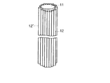
図1は本発明による地中水位水圧検出装置の第1の実施形態を示す全体構成図である。
【0024】
図1において、1a,1b,…,1nは、軸方向長さL1が例えば2〜2.5mの塩化ビニール等からなる単位円筒体、2a,2b,…2mは各単位円筒体1a,1b,…,1n相互間を結合する軸方向長さL2が例えば0.3mの塩化ビニール等の絶縁物からなる円筒状のジョイントで、これらは一体型の芯材11として構成される。
【0025】
この芯材11の外周面に導体の表面を絶縁物で被覆してなる複数本の電極用およびコモン電極用電気ケーブル12,12´が軸方向に沿ってそれぞれ配設される。この場合、これら電極用およびコモン電極用電気ケーブル12,12´は、芯材11の単位円筒体1a,1b,…,1nにそれぞれ対応する水位検出部を構成している。
【0026】
また、芯材11の各ジョイント2a,2b,…2n内に水圧センサ13がそれぞれ設けられ、各水圧センサ13は間隙水圧検出部を構成するものである。
【0027】
上記各水位検出部は、図2に示すように複数本(本例では10本)の電極用電気ケーブル12に対してそれぞれ軸方向の予め定められた一箇所の部位の絶縁物12aを除去して、導電部12bを露出させてある。この場合、導電部12bは一定長さとし、かつ各電気ケーブル12に対して一定の間隔でそれぞれずらせた電極として形成される。
【0028】
また、複数本(本例では4本)のコモン電極用電気ケーブル12´は、水位検出部の位置(図2では第1ブロックから第4ブロックとして示す)に応じてそれぞれ軸方向長さが異なり、該当する水位検出部に相当する部位の絶縁物12a´を除去して導電部12b´を露出させ、コモン電極として形成される。
【0029】
これら複数本の電極用電気ケーブル12およびコモン電極用電気ケーブル12´は、図3に示すように芯材11の外周面に軸方向に沿って配設され、これらを一体的に束ねて電極式水位センサを構成する。
【0030】
一方、芯材11の各ジョイント内に設けられる水圧センサ13としては、一般に市販されている例えばひずみゲージが用いられ、その受圧部を図4に示すようにジョイント2の内周面に設けられた開口部に臨ませて配設される。この場合、開口部には水圧を水圧センサ13に伝達するが、ジョイント2内部への水の浸入を阻止する機能を有するフィルタ14により覆われている。
【0031】
また、この水圧センサ13には、電気ケーブル15が接続され、この電気ケーブル15は水圧センサ13により検出された水圧に応じた電気信号を芯材11の各単位円筒体2a,2b,…2n内を通して地上側に伝送するものである。
【0032】
図5は芯材11の外周面に軸方向に沿って配設された電極用およびコモン電極用電気ケーブル12,12´と各ジョイント2a,2b,…2n内に設けられた水圧センサ13およびその電気ケーブル15の取付け状態を示している。
【0033】
このように芯材11に取り付けられた電極用およびコモン電極用電気ケーブル12,12´により構成された電極式水位センサおよび各ジョイント2内に設けられた水圧センサ13を図示しないボーリング装置により地面を掘削して形成されたボーリング穴に埋設される。
【0034】
一方、地上側には、図2に示すように計測ターミナル16および地すべり予測装置17が設置される。
【0035】
上記計測ターミナル16は、電極切換器18とコモン電極切換器19を備え、電極切換器18は固定接点18a,18b,…に前述した電極用ケーブル12の導体がそれぞれ接続され、可動接点18sに直流電源20と計測器21の一端が接続される。また、コモン電極切換器19は固定接点19a,19b,…に前述したコモン電極用ケーブル12´の導体がそれぞれ接続され、可動接点19sに抵抗計21の他端が接続される。
【0036】
上記地すべり予測装置17は、電極切換器18とコモン電極切換器19に切換指令を順次与える切換制御部22と、この切換制御部22からの切換指令と計測器21で計測される抵抗値が入力され、水位検出位置とそのデータを読込む水位データ読取部23と、水圧センサ13で検出されたブロック毎(図2では第1ブロック〜第4ブロック)の水圧検出信号を読込む水圧データ読取部24と、これら水位データ読取部23および水圧データ読取部23によりそれぞれ読取った水位データおよび水圧データをその位置データとともに記憶する記憶部25と、水位データ読取部22および水圧データ読取部23によりそれぞれ読取った水位データおよび水圧データに基づいて地すべりの発生の有無を予測判定し、地すべり発生が予測されるとその旨を出力する地すべり発生予測判定部26とを備えている。
【0037】
次に上記のように構成された地中水位水圧検出装置の作用を図6に示すフローチャートを参照しながら説明する。
【0038】
いま、地中の浸透水が図2に示す第3ブロックと第4ブロックとの間の図示Xの範囲に浸透しているものとする。また、このとき地上側の計測ターミナル16においては、地すべり予測装置17の切換制御装置22から出される切換指令により電極切換器18とコモン電極切換器19がそれぞれ順次切換動作しているものとする。
【0039】
このような動作過程で、コモン電極切換器19の可動接点19sが固定接点19aに切換えられているとき電極切換器18の可動接点18sが固定接点18aに切換えられると、固定接点18aにつながる電極用ケーブル12の第3ブロックに相当する位置の導電部と固定接点19aにつながるコモン電極用ケーブル12´の第3ブロックに相当する位置の導電部との間が導通状態となり、この電極用ケーブル12の抵抗値が変化する。
【0040】
この抵抗値の変化は計測器21にて電気的に計測され、その計測データが地すべり予測装置17に伝送される。
【0041】
一方、地すべり予測装置17においては、図6に示すように水位データ読取部23により水位データを読込み(ステップS1)、そのデータを切換制御部22からの切換指令から得られる位置データとともに記憶部25に記憶させるとともに、地すべり発生予測判定部26に入力する。ここで、位置データはコモン電極切換器19の切換位置からいずれのブロックに対応する水位検出部かを特定することで得られ、また水位データはこの特定された水位検出部における導電部の位置、つまり電極切換器18の切換位置を特定することで得られる。
【0042】
この地すべり発生予測判定部26では、水位データをもとに水位があるか否かを判定し(ステップS2)、水位があればその水位位置を確認する(ステップS3)。
【0043】
また、地すべり予測装置17においては、各ジョイントに設けられている水圧センサ13で検出された水圧データを水圧データ読取部24により読取り、そのデータを記憶部25に記憶させるとともに、地すべり発生予測判定部26に入力する。
【0044】
この地すべり発生予測判定部26では、水圧データ読取部24より入力される水圧データの中から前記水位の存在する位置に該当する水圧データを取込んで(ステップS4)、その水圧が水圧基準値を超えているか否かを判定し(ステップS5)、超えている場合は地すべり発生の可能性が高いと予測して注意を促す信号を出力する(ステップS6)。
【0045】
このように本実施形態では、複数個の単位円筒体1a,1b,…,1n相互間を円筒状のジョイント2a,2b,…2mで結合して構成される一体型の芯材11の外周面に導体の表面を絶縁物で被覆してなる複数本の電極用およびコモン電極用電気ケーブル12,12´を軸方向に沿ってそれぞれ配設するとともに、各円筒体に対応する部分を水位検出部とし、電極用電気ケーブル12に対してそれぞれ軸方向に異なる位置で且つ予め定められた一箇所の部位の絶縁物を除去して導電部を電極として形成し、コモン電極用電気ケーブル12´に対しては各単位円筒体の軸方向長さに対応する部位の絶縁物を除去してコモン電極を形成して電極式水位センサを構成し、また各ジョイント2a,2b,…2m内にその周面に設けられた開口部に受圧部を臨ませてひずみゲージ等の水圧センサ13をそれぞれ設ける構成として、一つのボーリング穴に埋設するようにしたものである。
【0046】
従って、地中深さの異なる複数層のいずれの層に浸透水が存在していてもその層に対応する部位の水位検出部の導電部とコモン電極とが浸透水に接触することで、その部位の浸透水の存在を電気的に検出することができるとともに、この部位の水圧センサ13により水圧を検出することができる。これにより地下水の位置、大きさの値を簡便に、かつより正確に同時に得ることができる。
【0047】
また、芯材11は複数の単位円筒体をジョイントにより結合して一体型として、各単位円筒体に対応させて水位検出部を構成し、各ジョイントに対応させて間隙水圧検出部を構成するようにしているので、地中の深さに応じて単位円筒体の個数を増減してジョイントにより結合するだけで芯材11の長さを調整することができる。
【0048】
さらに、各ジョイント2の周面に設けられた開口部に水の浸入を阻止し且つ水圧のみを水位センサ13の受圧部に伝達可能なフィルタ14を設けてあるので、浸透水の水圧を正確に検出することができる。
【0049】
他方、地上側には計測ターミナル16および地すべり予測装置17を設置し、計測ターミナル16には電極切換器18とコモン電極切換器19を備えて、電極用ケーブル12およびコモン電極用ケーブル12´を順次切換えて計測器21により電気抵抗を計測し、また地すべり予測装置17には計測ターミナル16の計測器21にて計測された水位データを位置データとともに読取る水位データ読取部23、各ジョイントに対応させて設けられた水圧センサ13からの水圧データを読取る水圧データ読取部24およびこれらの読取部により読取られた水位データおよび水圧データに基づいて地すべりの発生の有無を予測判定する地すべり発生予測判定部26を備える構成としたものである。
【0050】
従って、地すべり発生予測判定部26では、水位センサにより検出された水位データとその位置データおよび水圧センサにより検出されたその水位位置の水圧データから地すべり発生を予測してその旨を出力するようにしたので、水位センサのみによる測定結果の判定に比べてより正確で且つ迅速な判定を行うことができる。
【0051】
因みに、地すべり要因の解析結果、必要な測定値はすべり面位置における間隙水圧であることが知られているが、すべり面が深い位置にあったり、地すべり移動によっては測定が不可能であることなどの理由から水位計によって測定される地下水の静水圧をもって間隙水圧に代えることが広く行なわれている。
【0052】
これに対して、本発明では、必要個数の単位円筒体をジョイントでつなぐことでその軸方向長さを任意に調整でき、且つ各単位円筒体に対応させて水位検出部を構成し、また各ジョイント内に水圧センサを設けてその検出部のみジョイントの周面の一部に設けた開口部に臨ませて間隙水圧を検出できるようにしているので、すべり面の深い位置や、地すべり移動の可能性の高い場所でも水位と水圧の両方を同時に検出することができ、地下水の挙動を計測することができる。
【0053】
また、水位センサにより検出された水位とその位置が特定されると同時にその水位位置における水圧センサにより水圧を検出しているので、例えば水位センサにより水位を検出していないにもかかわらず、水圧センサにより水圧が検出されたり、その逆であったりするような場合には何れかのセンサに故障があることを容易に判断することができる。
【0054】
本発明は上記実施形態で述べた構成に限定されるものではなく、その一部を次のようにしても同様に実施できるものである。
【0055】
上記実施形態では、芯材11を構成する単位円筒体1a,1b,…およびジョイント2a,2b,…の材料として塩化ビニールを用いたが、強度を有するプラスチックやアルミニウム、薄いステンレス等の加工し易い材料を使用しても良い。
【0056】
また、上記実施形態では、各ジョイント内に設けられる水圧センサ13としてひずみゲージを用いたが、圧電式や半導体式など軽量小型で受圧部の変化を電気信号として取出せるものであればどのようなタイプのものであっても良い。
【0057】
さらに、上記実施形態において、複数の単位円筒体をジョイントにより結合する手段として、ねじ込み方式や嵌め込み方式など着脱できるものであればどのような方式で結合しても良い。
【0058】
【発明の効果】
以上述べたように本発明によれば、電気ケーブルによる電極式水位センサと間隙水圧センサとを組合せることにより、任意地層の地下水の挙動をシンプルな構造にして簡易にかつより正確に検出できる地中水位水圧検出装置を提供できる。
【図面の簡単な説明】
【図1】本発明による地中水位水圧検出装置の実施形態を示す構成図。
【図2】同実施形態において、要部を展開して平面的に表した回路構成図。
【図3】同実施形態における電極式水位センサを示す斜視図。
【図4】同実施形態において、ジョイント内に設けられた水圧センサの状態を示す図。
【図5】同実施形態において、芯材に電極式水位センサと水圧センサを配設した状態を示す平面図。
【図6】同実施形態の作用を説明するためのフローチャート。
【図7】従来の地中水位検出装置の一例を示す構成図。
【符号の説明】
1,1a,1b,…,1n…単位円筒体
2,2a,2b,…2n…ジョイント
11…芯材
12,12´…電極用およびコモン電極用電気ケーブル
12a,12a´…絶縁物
12b,12b´…導電部
13…水圧センサ
14…フィルタ
15…電気ケーブル
16…計測ターミナル
17…地すべり予測装置
18,19…電極およびコモン電極切換器
20…直流電源
21…計測器
22…切換制御器
23…水位データ読取器
24…水圧データ読取器
25…記憶部
26…地すべり発生予測判定部[0001]
TECHNICAL FIELD OF THE INVENTION
The present invention relates to an underground water level pressure detection device capable of easily and simultaneously measuring the water level and water pressure in the ground.
[0002]
[Prior art]
Conventionally, as a means for measuring the underground water level, a method of excavating the ground with a boring device and measuring the water accumulated in the excavated boring hole with a float is generally used.
[0003]
FIG. 7 is a configuration diagram showing an example of such a conventional float type water level meter.
[0004]
In FIG. 7, reference numeral 31 denotes a foundation concrete that has been driven into the ground, and the foundation concrete 31 has a through hole that passes through the ground from the ground surface. Reference numeral 32 denotes a cylindrical body buried in the ground through a through hole of the foundation concrete 31, and the cylindrical body 32 is formed by connecting a plurality of cylindrical parts having appropriate lengths according to the burial depth in the ground. A plurality of holes penetrating the inside and outside of the cylinder are provided along the axial direction.
[0005]
Reference numeral 33 denotes a case installed on the foundation concrete 31 with the cylindrical body 32 at the center, and a float driving device 34 is installed in the upper part of the case 33. The float driving device 34 vertically supports a wire 36 having a float 35 attached to the distal end thereof through the cylindrical body 32, and the float 35 moves up and down according to the water level accumulated in the lower part of the cylindrical body 32. Thereby, the wire 36 is wound up or down.
[0006]
Further, in the lower part of the case 33, the water level accumulated at the bottom in the cylindrical body 32 is measured by the measuring device 37 from the movement amount of the wire 36 wound up or down by the float driving device 34, and is measured by the measuring device 37. A transmitter 39 for transmitting the obtained data to a base station (not shown) through an output cable 38 buried underground is provided.
[0007]
In the underground water level detection device having such a configuration, when rainwater or the like that has fallen on the ground surface due to rainfall or the like penetrates into the ground, the water flows through a hole provided along the axial direction of the cylindrical body 32. Collect at the bottom inside. The water level collected at the bottom in the cylindrical body 32 is measured by the measuring device 37 from the amount of movement of the wire 36 wound up or down in accordance with the vertical movement of the float 35.
[0008]
However, such a float-type water gauge can measure the total amount of water collected at the bottom of a borehole, but specifies how much groundwater is flowing from which part of the stratum. I couldn't do that.
[0009]
Therefore, recently, as a groundwater measurement device that can determine which stratum is groundwater, a groundwater intake section divided between upper and lower inner and outer partitions corresponding to the aquifer based on boring detection between the inner pipe and the outer pipe has been developed. The strainer double pipe is formed and connected to each groundwater intake section using the inner space of the inner pipe, and is provided with a strainer double pipe provided with a measuring pipe extending above the inner pipe, and the strainer double pipe is inserted into the bore hole. There is a type in which groundwater in an aquifer is set in a groundwater intake section, groundwater in the groundwater intake section is introduced into a measuring pipe, and the water level of the groundwater is measured by a float (for example, Patent Document 1).
[0010]
On the other hand, in order to grasp the behavior of groundwater in a specific stratum, a pore pressure gauge has been devised (for example, Patent Document 2), and a method of measuring the pressure of groundwater stored in a specific stratum with a pressure gauge has also been devised. Has been
[0011]
[Patent Document 1]
JP 2001-173361 A
[Patent Document 2]
JP-A-10-82669
[Problems to be solved by the invention]
However, in the above-described groundwater measuring device, a groundwater intake section divided by a pair of upper and lower inner and outer partitions corresponding to the aquifer between the inner pipe and the outer pipe is provided as a strainer double pipe provided with a measuring pipe. Because it is formed to make it possible to determine which layer of groundwater it is, the overall structure is complicated, and the groundwater in the groundwater intake is introduced into the measurement pipe and the water level is measured with a float, There were problems with performance and reliability.
[0014]
In addition, a pore pressure gauge designed to grasp the behavior of groundwater in a specific stratum has a problem that if there is a crack in the ground to be measured, the water pressure escapes from the crack and the water pressure cannot be measured accurately. Then, the upper and lower parts of the stratum where the water pressure gauge is to be installed must be sealed so that the pressure is not escaped, so special technology is required for installation of the water pressure gauge, making it difficult to install easily. was there.
[0015]
The present invention solves the above-described problems and combines an electrode-type water level sensor with an electric cable and a pore water pressure sensor to easily and more accurately make the behavior of groundwater in any formation a simple structure. It is an object of the present invention to provide an underground water level water pressure detection device capable of detecting.
[0016]
[Means for Solving the Problems]
In order to achieve the above object, the present invention constitutes an underground water level pressure detecting device by the following means.
[0017]
According to a first aspect of the present invention, a plurality of unit cylindrical bodies are connected to each other by a cylindrical joint to form an integral core material, and the outer peripheral surface of the core material is covered with a conductor surface by an insulator. A plurality of electrical cables for the electrodes and a common electrode are arranged along the axial direction, and a portion corresponding to each cylindrical body is used as a water level detecting portion, and each of the electrical cables for the electrodes is axially disposed relative to the electrical cable for the electrodes. The conductive portion is formed as an electrode by removing the insulator at a different position and at a predetermined portion, and for the common electrode electric cable, a portion corresponding to the axial length of each unit cylindrical body is formed. An electrode-type water level sensor is formed by removing an insulator to form a common electrode, and each of the joints is provided with a water pressure sensor facing a pressure receiving portion at an opening provided on a peripheral surface thereof, Drilling underground Embedded in a borehole that.
[0018]
According to a second aspect of the present invention, in the underground water level detecting apparatus according to the first aspect of the present invention, the unit cylindrical body and the joint constituting the core member are detachably connected by screwing or fitting. It is.
[0019]
According to a third aspect of the present invention, in the underground water level water pressure detecting device according to the first aspect of the present invention, water is prevented from entering into openings provided on the peripheral surface of each of the joints and only the water pressure is reduced to the water level. A filter capable of transmitting the pressure is provided at the pressure receiving portion of the sensor.
[0020]
According to a fourth aspect of the present invention, in the underground water level detecting apparatus according to the first aspect of the present invention, an electric output is obtained by sequentially switching the electrode cable and the common electrode cable installed on the ground side. An electrode switching means and a common electrode switching means, and measuring an electric resistance between a conductive part of the electrode and the common electrode cable and a common electrode from an electric output obtained from these electrodes and the common electrode switching means, and The water level detection unit is specified from the switching position of the common electrode switching unit, and the underground water level is detected based on the position of the conductive unit in the water level detection unit.
[0021]
The invention according to claim 5 is the underground water level water pressure detection device according to the invention according to claim 4, wherein the water level data and the position data detected based on the position of the conductive part in the water level detection unit are taken, and A landslide occurrence prediction determining means is provided, which takes in water pressure data detected by the water pressure sensor at a portion corresponding to a water level detection unit and predicts whether or not a landslide has occurred based on the water level data and the water pressure data.
[0022]
BEST MODE FOR CARRYING OUT THE INVENTION
Hereinafter, embodiments of the present invention will be described with reference to the drawings.
[0023]
FIG. 1 is an overall configuration diagram showing a first embodiment of an underground water level pressure detection device according to the present invention.
[0024]
In FIG. 1, 1a, 1b,..., 1n are unit cylinders made of vinyl chloride or the like having an axial length L1 of, for example, 2 to 2.5 m, 2a, 2b,. .., 1n are cylindrical joints made of an insulator such as vinyl chloride having an axial length L2 of, for example, 0.3 m, which are formed as an integral core material 11.
[0025]
A plurality of electrode and common electrode electrical cables 12, 12 'each having a conductor surface covered with an insulator are provided on the outer peripheral surface of the core material 11 along the axial direction. In this case, the electric cables 12 and 12 ′ for the electrodes and the common electrode constitute water level detecting sections respectively corresponding to the unit cylindrical bodies 1 a, 1 b,.
[0026]
Further, a water pressure sensor 13 is provided in each of the joints 2a, 2b,... 2n of the core material 11, and each water pressure sensor 13 constitutes a pore water pressure detection unit.
[0027]
As shown in FIG. 2, each of the water level detection units removes the insulator 12 a at a predetermined portion in the axial direction from a plurality (ten in this example) of the electrode electric cables 12. Thus, the conductive portion 12b is exposed. In this case, the conductive portion 12b is formed as an electrode having a fixed length and being shifted from the electric cable 12 at a fixed interval.
[0028]
A plurality of (four in this example) common electrode electric cables 12 ′ have different axial lengths depending on the position of the water level detection unit (shown as the first to fourth blocks in FIG. 2). Then, the insulator 12a 'at a portion corresponding to the corresponding water level detecting portion is removed to expose the conductive portion 12b', thereby forming a common electrode.
[0029]
The plurality of electrode electric cables 12 and the common electrode electric cables 12 ′ are disposed along the axial direction on the outer peripheral surface of the core material 11 as shown in FIG. Construct a water level sensor.
[0030]
On the other hand, as the water pressure sensor 13 provided in each joint of the core material 11, for example, a commercially available strain gauge is used, and the pressure receiving portion is provided on the inner peripheral surface of the joint 2 as shown in FIG. It is arranged facing the opening. In this case, the opening is covered with a filter 14 that transmits the water pressure to the water pressure sensor 13 but has a function of preventing water from entering the joint 2.
[0031]
An electric cable 15 is connected to the water pressure sensor 13. The electric cable 15 transmits an electric signal corresponding to the water pressure detected by the water pressure sensor 13 to each of the unit cylindrical bodies 2 a, 2 b,. Is transmitted to the ground side through
[0032]
FIG. 5 shows an electric cable 12, 12 'for electrodes and common electrodes arranged along the axial direction on the outer peripheral surface of the core material 11, and a water pressure sensor 13 provided in each of the joints 2a, 2b,. The state of attachment of the electric cable 15 is shown.
[0033]
The electrode type water level sensor constituted by the electrode and common electrode electric cables 12 and 12 'attached to the core member 11 and the water pressure sensor 13 provided in each joint 2 are grounded by a boring device (not shown). It is buried in a borehole formed by excavation.
[0034]
On the ground side, on the other hand, a measurement terminal 16 and a landslide prediction device 17 are installed as shown in FIG.
[0035]
The measurement terminal 16 includes an electrode switch 18 and a common electrode switch 19. The electrode switch 18 has fixed contacts 18a, 18b,... Connected to the conductors of the above-described electrode cable 12, and a movable contact 18s. The power supply 20 and one end of the measuring instrument 21 are connected. In the common electrode switch 19, the conductors of the common electrode cable 12 'described above are respectively connected to the fixed contacts 19a, 19b, ..., and the other end of the ohmmeter 21 is connected to the movable contact 19s.
[0036]
The landslide prediction device 17 is provided with a switching control unit 22 for sequentially giving a switching command to the electrode switching unit 18 and the common electrode switching unit 19, and a switching command from the switching control unit 22 and a resistance value measured by the measuring device 21. A water level data reading unit 23 for reading the water level detection position and its data, and a water pressure data reading unit for reading a water pressure detection signal for each block (first block to fourth block in FIG. 2) detected by the water pressure sensor 13. 24, a storage unit 25 for storing the water level data and the water pressure data read by the water level data reading unit 23 and the water pressure data reading unit 23 together with the position data, and a water level data reading unit 22 and a water pressure data reading unit 23, respectively. Based on the measured water level data and water pressure data, it is predicted to determine whether a landslide has occurred. And a landslide prediction judgment unit 26 outputs the fact.
[0037]
Next, the operation of the underground water level pressure detecting device configured as described above will be described with reference to the flowchart shown in FIG.
[0038]
Now, it is assumed that the infiltrated water in the ground has penetrated into a range indicated by X between the third block and the fourth block shown in FIG. At this time, in the measurement terminal 16 on the ground side, it is assumed that the electrode switch 18 and the common electrode switch 19 are sequentially switched by the switch command issued from the switch controller 22 of the landslide prediction device 17.
[0039]
In such an operation process, when the movable contact 18s of the electrode switch 18 is switched to the fixed contact 18a while the movable contact 19s of the common electrode switch 19 is switched to the fixed contact 19a, the electrode for the electrode connected to the fixed contact 18a is switched. A conductive state is established between the conductive portion at a position corresponding to the third block of the cable 12 and the conductive portion at a position corresponding to the third block of the common electrode cable 12 'connected to the fixed contact 19a. The resistance value changes.
[0040]
The change in the resistance value is electrically measured by the measuring device 21, and the measured data is transmitted to the landslide prediction device 17.
[0041]
On the other hand, in the landslide prediction device 17, as shown in FIG. 6, water level data is read by the water level data reading section 23 (step S1), and the data is stored in the storage section 25 together with position data obtained from a switching command from the switching control section 22. And inputs it to the landslide occurrence prediction determination unit 26. Here, the position data is obtained by specifying which block the water level detector corresponds to from the switching position of the common electrode switch 19, and the water level data is the position of the conductive part in the specified water level detector, That is, it can be obtained by specifying the switching position of the electrode switch 18.
[0042]
The landslide occurrence prediction determination unit 26 determines whether there is a water level based on the water level data (step S2), and if there is a water level, checks the water level position (step S3).
[0043]
In the landslide prediction device 17, the hydraulic pressure data detected by the hydraulic pressure sensors 13 provided at each joint is read by the hydraulic pressure data reading unit 24, and the data is stored in the storage unit 25. Input to 26.
[0044]
The landslide occurrence prediction determination unit 26 fetches the hydraulic pressure data corresponding to the position where the water level exists from the hydraulic pressure data input from the hydraulic pressure data reading unit 24 (step S4), and the hydraulic pressure is set to the hydraulic pressure reference value. It is determined whether or not it has exceeded (step S5), and if it has exceeded, a signal that warns the user by predicting that the possibility of occurrence of a landslide is high (step S6).
[0045]
As described above, in the present embodiment, the outer peripheral surface of the integral core member 11 formed by connecting the plurality of unit cylindrical bodies 1a, 1b,..., 1n with the cylindrical joints 2a, 2b,. And a plurality of electric cables 12 and 12 'for electrodes and a common electrode, each of which has a conductor surface coated with an insulator, are respectively disposed along the axial direction, and a portion corresponding to each cylinder is provided with a water level detection unit. The conductor is formed as an electrode by removing the insulator at a predetermined position at different positions in the axial direction with respect to the electric cable 12 for the electrode to form a conductive portion as an electrode. In addition, a common electrode is formed by removing an insulator at a portion corresponding to the axial length of each unit cylindrical body to form an electrode type water level sensor, and its peripheral surface is formed in each joint 2a, 2b,. Pressure in the opening provided in the In this configuration, the water pressure sensors 13 such as strain gauges are provided so as to face each other, and are buried in one boring hole.
[0046]
Therefore, even if infiltration water is present in any of a plurality of layers having different underground depths, the conductive portion of the water level detection unit and the common electrode of the portion corresponding to the layer contact the infiltration water, The presence of permeated water at the site can be electrically detected, and the water pressure can be detected by the water pressure sensor 13 at this site. Thereby, the value of the position and size of the groundwater can be obtained easily and more accurately at the same time.
[0047]
Further, the core member 11 is configured such that a plurality of unit cylinders are joined by a joint to form an integral type, and a water level detection unit is configured to correspond to each unit cylinder, and a pore water pressure detection unit is configured to correspond to each joint. Therefore, the length of the core material 11 can be adjusted only by increasing / decreasing the number of unit cylindrical bodies according to the depth in the ground and connecting them by a joint.
[0048]
Furthermore, since the filter 14 that prevents water from entering into the opening provided on the peripheral surface of each joint 2 and can transmit only the water pressure to the pressure receiving portion of the water level sensor 13 is provided, the water pressure of the permeated water can be accurately measured. Can be detected.
[0049]
On the other hand, a measurement terminal 16 and a landslide prediction device 17 are installed on the ground side, and the measurement terminal 16 is provided with an electrode switch 18 and a common electrode switch 19 to sequentially connect the electrode cable 12 and the common electrode cable 12 ′. The electrical resistance is measured by the measuring device 21 by switching, and the landslide prediction device 17 is provided with a water level data reading section 23 for reading the water level data measured by the measuring device 21 of the measuring terminal 16 together with the position data, and corresponding to each joint. A water pressure data reading unit 24 for reading the water pressure data from the provided water pressure sensor 13 and a landslide occurrence prediction determination unit 26 for predicting the occurrence of a landslide based on the water level data and the water pressure data read by these reading units. It is configured to be provided.
[0050]
Therefore, the landslide occurrence prediction determination unit 26 predicts the occurrence of a landslide from the water level data detected by the water level sensor and its position data and the water pressure data of the water level position detected by the water pressure sensor, and outputs the fact. Therefore, more accurate and quick determination can be performed as compared with the determination of the measurement result using only the water level sensor.
[0051]
Incidentally, as a result of analysis of the landslide factor, it is known that the required measurement value is the pore water pressure at the slip surface position, but that the slip surface is at a deep position or that measurement is not possible due to landslide movement etc. For this reason, it has been widely practiced to use the hydrostatic pressure of groundwater measured by a water gauge to replace pore water pressure.
[0052]
On the other hand, in the present invention, the required length of unit cylinders can be arbitrarily adjusted by connecting the required number of unit cylinders with a joint, and a water level detection unit is configured to correspond to each unit cylinder. A water pressure sensor is installed in the joint, and only the detection part faces the opening provided in a part of the peripheral surface of the joint so that the pore water pressure can be detected, so it is possible to move deep in the slip surface or move landslide Even in places with high performance, both water level and water pressure can be detected simultaneously, and the behavior of groundwater can be measured.
[0053]
Further, since the water level detected by the water level sensor and its position are specified and the water pressure is detected by the water pressure sensor at the water level position, for example, the water pressure sensor is not detected even though the water level sensor detects the water level. Accordingly, when the water pressure is detected or vice versa, it can be easily determined that any of the sensors has a failure.
[0054]
The present invention is not limited to the configuration described in the above embodiment, and a part of the configuration can be similarly implemented as follows.
[0055]
In the above embodiment, vinyl chloride is used as the material of the unit cylindrical bodies 1a, 1b,... And the joints 2a, 2b,. Materials may be used.
[0056]
In the above-described embodiment, a strain gauge is used as the water pressure sensor 13 provided in each joint. It may be of the type.
[0057]
Further, in the above embodiment, as a means for connecting a plurality of unit cylinders by a joint, any unit that can be detached, such as a screwing method or a fitting method, may be used.
[0058]
【The invention's effect】
As described above, according to the present invention, by combining the electrode type water level sensor with the electric cable and the pore water pressure sensor, the groundwater in an arbitrary stratum can be easily and more accurately detected with a simple structure. It is possible to provide a middle water level pressure detecting device.
[Brief description of the drawings]
FIG. 1 is a configuration diagram showing an embodiment of an underground water level water pressure detection device according to the present invention.
FIG. 2 is a circuit configuration diagram in which main parts are developed and planarly shown in the embodiment.
FIG. 3 is an exemplary perspective view showing an electrode type water level sensor according to the embodiment;
FIG. 4 is a diagram showing a state of a water pressure sensor provided in a joint in the embodiment.
FIG. 5 is a plan view showing a state in which an electrode type water level sensor and a water pressure sensor are provided on a core material in the embodiment.
FIG. 6 is a flowchart for explaining the operation of the embodiment.
FIG. 7 is a configuration diagram showing an example of a conventional underground water level detection device.
[Explanation of symbols]
1, 1a, 1b,..., 1n unit cylindrical body 2, 2a, 2b,... 2n joint 11 core material 12, 12 ′ electric cable for electrodes and common electrode 12a, 12a ′ insulator 12b, 12b '... Conducting part 13 ... Water pressure sensor 14 ... Filter 15 ... Electric cable 16 ... Measurement terminal 17 ... Landslide prediction device 18, 19 ... Electrode and common electrode switch 20 ... DC power supply 21 ... Measuring device 22 ... Switching controller 23 ... Water level Data reader 24 ... Hydraulic data reader 25 ... Storage unit 26 ... Landslide occurrence prediction determination unit