【0001】
【発明の属する技術分野】
本発明は、トレッド部の溝底部を補強して耐久性を高めた空気入りタイヤに関する。
【0002】
【従来の技術】
タイヤの周方向外側を構成するトレッド部には溝が設けられている。この溝の深さについては、一般に、タイヤ周方向に沿った周方向溝が最も深い。
【0003】
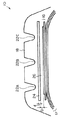
この溝の構造を強化するために、図3に示すような空気入りタイヤ80が提案されている。この空気入りタイヤ80には、ベルト層86とトレッド部88の周方向溝(主溝)82A〜Cとの間に、周方向に沿ったナイロン製のコード90を有する補強層84A〜Cをそれぞれ配設する対策が行われている。また、同様の対策を行った例として、ベルト層の補強用コードを実質上タイヤ周方向に配設すると共に、補強層として不織布―ゴムの複合体を用いる例(例えば特許文献1参照)が提案されている。
【0004】
また、溝の構造を強化する別の対策として、ゴム製の補強層を設ける例(例えば特許文献2参照)が提案されている。
【0005】
【特許文献1】
特開2002−2219号公報
【特許文献2】
特開平4−306103号公報
【0006】
【発明が解決しようとする課題】
しかし、図3や特許文献1に開示されたように、周方向に沿ったナイロン製のコードを設ける対策を行った場合、溝底から発生したカット(亀裂)がコードにまで到達すると、タイヤ外側からカットに入り込んだ水がコード内を伝播し、錆が形成される領域が広がるという難点があった。
【0007】
また、特許文献2に開示されたように、ゴム製の補強層を設けるのみの対策を行った場合、補強による効果があまり得られないという難点があった。
【0008】
本発明は、上記事実を考慮して、耐久性に優れた空気入りタイヤを提供することを課題とする。
【0009】
【課題を解決するための手段】
本発明者は、溝底からカットが発生する原因を検討した。そして、図3に示したように、従来の空気入りタイヤ80では、ベルト層86と補強層84A〜Cとにそれぞれ挟まれているゴム層96A〜Cの厚みDが、補強層84の厚みdに比べてかなり薄いことを見い出した。
【0010】
そこで、本発明者は、このゴム層96の厚みを所定厚以上にすることにより、このゴム層に緩衝材としての機能を持たせることを考え付いた。更に、補強層として複数種の繊維からなる不織布を設けることも考え付き、検討を重ね、本発明を完成するに至った。
【0011】
請求項1に記載の発明は、カーカスと、前記カーカスのタイヤ半径方向外側に設けられたベルト層と、前記ベルト層のタイヤ半径方向外側に設けられ、周方向に連なる複数本の周方向溝を有するトレッド部と、前記ベルト層と前記複数本の周方向溝との間に設けられた補強層と、を有する空気入りタイヤにおいて、前記補強層として2種以上の繊維からなる不織布を設けると共に、前記補強層と前記ベルト層とによって挟まれるゴム層の厚みを前記補強層の厚み以上にしたことを特徴とする。
【0012】
空気入りタイヤのカーカスの両端部は、それぞれビードコアで折り返されている。また、ベルト層を構成するコードがタイヤ周方向と交差する向きになるように、ベルト層が加工されて設けられている。ベルト層を構成するコードは、タイヤ周方向と交差することが好ましい(すなわちタイヤ周方向に沿っていないことが好ましい)。ベルト層は2層以上のベルトプライで構成されることが多く、この場合、各ベルトプライのコードの向きが互いに交差していることが好ましい。
【0013】
不織布を構成する繊維は、有機繊維、無機繊維等、特に限定しない。
【0014】
空気入りタイヤは、ラジアルタイヤや、バイアスタイヤ、チューブレスタイヤであってもよく、空気入りタイヤの種類は特に限定しない。
【0015】
このように、請求項1に記載の発明では、補強層に繊維が含まれているので、補強効果を高めることができる。
【0016】
また、不織布を用いているので繊維の方向が一定方向に向いていない。従って、周方向溝の溝底にカットが生じてこのカットを経由した水が補強層に到達しても、この水が補強層に沿って一方向に伝播することを防止できるので、ベルトスチールコードの錆の伝播を抑制することができる。
【0017】
更に、不織布が2種以上の繊維で構成されているので、不織布に複合機能を持たせることが可能になると共に、カット先端が補強層に到達しても、この補強層を、不織布が1種の繊維で構成されている場合に比べて裂け難くすることができる。
【0018】
また、補強層とベルト層とによって挟まれるゴム層の厚みが補強層の厚み以上にされているので、このゴム層による緩衝効果が充分に得られ、路面からの衝撃によるカットが空気入りタイヤに生じ難く、特に溝底部で生じるカット数を大幅に低減させることができ、耐久性が高い空気入りタイヤが実現される。
【0019】
なお、補強層を複数層設けてもよい。また、補強層とベルト層とによって挟まれるゴム層の厚みに分布を持たせてもよい。例えば、タイヤ赤道面近傍と、タイヤ両側部近傍とでこのゴム層の厚みを異ならせてもよい。
【0020】
請求項2に記載の発明は、前記不織布は、目付けが20〜100g/m2の範囲内で、フィラメント繊維の径が0.02〜0.05mmの範囲内であることを特徴とする。
【0021】
これにより、カットに対する補強の効果を高められるという効果が得られる。
【0022】
目付けが上記範囲よりも低いと補強効果が低くなるという不具合が生じ易く、目付けが上記範囲よりも高いとフィラメント繊維間にゴムが入り込み難くなることにより、フィラメント繊維とゴムとの接着力が低下して補強効果が低くなるという不具合が生じ易い。また、フィラメント繊維の径が上記範囲よりも低いと、フィラメント繊維間にゴムが入り込み難くなることにより、フィラメント繊維とゴムとの接着力が低下して補強効果が低くなるという不具合が生じ易く、フィラメント繊維の径が上記範囲よりも高いと、フィラメント繊維同士のからみ合いが少なくなるため、複合体としての機能が低下することにより補強効果が低くなるという不具合が生じ易い。
【0023】
請求項3に記載の発明は、前記不織布を構成する繊維として、弾性率が5000kg/mm2以上の高弾性率ヤーンと、弾性率が200kg/mm2以上で1000kg/mm2以下の低弾性率ヤーンと、が用いられていることを特徴とする。
【0024】
これにより、高弾性率ヤーンによって補強効果を高めることができると共に、低弾性率ヤーンによってゴムと補強層との接着性を確保することができる。
【0025】
ヤーンは撚り糸でないので、ヤーンの弾性率を測定するには原糸の弾性率を測定する。すなわち、無撚り、無熱処理素材の引張試験を行って得られたS−Sカーブに基づいて、原糸の破断時の応力と伸びとを求める。更に、破断時の断面積に換算した真応力を求め、弾性率を算出する。
【0026】
高弾性率ヤーンと低弾性率ヤーンとの構成比率については、補強効果を高める効果を顕著に出したい場合には高弾性率ヤーンの比率を高めてもよく、ゴムと補強層との接着性を高める効果を顕著に出したい場合には低弾性率ヤーンの比率を高めてもよい。更には、この比率を部分的に異ならせ、意図する部位に意図する機能を持たせることも可能である。また、高弾性率ヤーンが、材質や径が互いに異なる複数種の高弾性率ヤーンで構成されていてもよいし、同様に、低弾性率ヤーンが、材質や径が互いに異なる複数種の低弾性率ヤーンで構成されていてもよい。
【0027】
請求項4に記載の発明は、前記高弾性率ヤーンの材質が芳香族ポリアミド又はポリオレフィンケトン(POK)であり、前記低弾性率ヤーンの材質がナイロン又はポリエチレンテレフタレート(PET)であることを特徴とする。
【0028】
これにより、簡易に入手できるヤーンを高弾性率ヤーン及び低弾性率ヤーンとして用いることができる。なお、これらの材質以外のヤーンを適宜選択してもよい。
【0029】
請求項5に記載の発明は、前記複数本の周方向溝の溝下にのみ前記補強層をそれぞれ配置したことを特徴とする。
【0030】
これにより、補強層の機能を維持しつつ補強層の重量を最小限にすることが可能になり、空気入りタイヤの重量低減やコスト削減を実現できる。なお、溝の種類、位置等に応じて補強層の寸法を変更してもよく、これにより、この効果をより顕著にすることが可能である。
【0031】
【発明の実施の形態】
以下、実施形態を挙げ、本発明の実施の形態について説明する。
【0032】
[第1形態]
まず、第1形態について説明する。図1に示すように、空気入りタイヤ10は、両端部がそれぞれビードコア(図示せず)に巻かれ、実質上ラジアル方向に延びるコードを含むカーカス12を備えている。カーカス12は、1層又は複数層で構成される。
【0033】
カーカス12のクラウン部のタイヤ径方向外側には、複数枚(例えば2枚)のベルトプライが重ねられたベルト層16が埋設されている。各ベルトプライは、ベルトプライを構成するコードが、タイヤ周方向に交差すると共に互いに交差する方向に向くように埋設されている。
【0034】
また、カーカス12のタイヤ径方向内側にはインナーライナが設けられている。
【0035】
ベルト層16のタイヤ径方向外側には、溝を配設したトレッド部18が形成されている。図1に示すように、トレッド部18には、周方向に沿った複数本の主溝22A〜Cと、周方向と直交する方向に沿ったラグ溝(図示せず)と、が形成されている。一般に、主溝22のほうがラグ溝よりも深い。
【0036】
主溝22とベルト層16との間には補強層24が埋設されている。補強層24は、弾性率が5000kg/mm2以上である高弾性率ヤーンと、弾性率が200kg/mm2以上で1000kg/mm2以下である低弾性率ヤーンと、の混合ヤーンからなる不織布で構成される。高弾性率ヤーンは、例えば芳香族ポリアミド繊維(商品名「ケブラー」)又はポリオレフィンケトン(POK)からなるヤーンであり、低弾性率ヤーンは、例えばナイロン又はポリエチレンテレフタレート(PET)からなるヤーンである。
【0037】
これにより、高弾性率ヤーンによって補強効果を高めることができると共に、低弾性率ヤーンによってゴムと補強層との接着性を確保することができる。また、補強層24が不織布で構成されており、不織布の繊維が不揃いであるので、主溝22の溝底にカットが生じてカット先端が補強層24にまで到達しても、タイヤ外側からこのカットを経由して補強層24に到達した水が繊維にそって浸透し難い。
【0038】
また、補強層24とベルト層16とによって挟まれるゴム層26の厚みDは、補強層24の厚みd以上にされている。
【0039】
これにより、このゴム層26による緩衝効果が充分に得られ、路面からの衝撃によるカット(亀裂)が空気入りタイヤ10に生じ難くなっている。
【0040】
[第2形態]
次に、第2形態を説明する。第2形態では、第1形態と同様の構成要素には同じ符号を付してその説明を省略する。
【0041】
図2に示すように、第2形態に係る空気入りタイヤ30は、第1形態に比べ、補強層34の構成が異なる。
【0042】
補強層34Aは、主溝22Aに沿って主溝22Aの真下にのみ配置されており、補強層34B、34Cも、それぞれ、主溝22B、22Cに沿って主溝22B、22Cの真下にのみ配置されている。補強層34A〜Cの幅は、それぞれ、主溝22A〜Cの溝底の幅よりも若干幅広にされており、実質上溝幅に相当する溝底部分をカバーするようになっている。
【0043】
これにより、補強層34の機能を維持しつつ補強層34の重量を最小限にすることが可能になり、空気入りタイヤ30の重量低減やコスト低減を実現できる。なお、主溝22A〜Cの位置や寸法に応じて補強層34A〜Cの寸法を変更することが可能であり、これにより、この効果をより奏することができる。
【0044】
また、第2形態では、第1形態と同様、補強層34A〜Cとベルト層16とによってそれぞれ挟まれるゴム層36A〜Cの厚みDは、補強層34の厚みd以上にされており、このゴム層36A〜Cによる緩衝効果が得られ、路面からの衝撃によるカット(亀裂)が生じ難くなっている。
【0045】
[実験例]
第1形態で説明した空気入りタイヤ10、第2形態で説明した空気入りタイヤ30、及び、図3に示した従来の空気入りタイヤ80について、その性能を比較するための実験を行った。その際、以下の条件は同じにした。
【0046】
タイヤサイズ :235/75R15
リム :7 JJ
内圧 :230kPa
カーカス層を構成するコードの方向:タイヤ周方向に対して90°
カーカス層を構成するコードの材料:PET、1500d/2
カーカス層の構造 :2層折り返し構造
ベルト層を構成するコードの方向 :タイヤ周方向に対して22°で、互いに交差する方向
ベルト層を構成するコードの材料 :2スチール(1+6)
この条件のもと、補強層の構成や配置位置等を、表1に示すようにパラメータとして変更した。
【0047】
【表1】
この3種の空気入りタイヤで、悪路を200km走行させた後、1ヶ月間屋外に放置した。そして、1ヶ月後、ベルト層と補強層とに挟まれているゴム層をベルト層に沿って剥してベルト層を露出させ、ベルト層に到達しているカット数(亀裂数)をカウントすると共に、発生している錆の面積を測定した。
【0048】
そして、従来の空気入りタイヤ80(図3参照)に発生したカット数、及び、錆の面積を100として、空気入りタイヤ10に発生したカット数、及び、錆の面積を換算して表1に示す。また、同様にして、空気入りタイヤ30に発生したカット数、及び、錆の面積も表1に示す。
【0049】
表1から判るように、従来の空気入りタイヤ80に発生したカット数を100とした場合、空気入りタイヤ10、30に発生したカット数は何れも70であり、従来の空気入りタイヤ80に比べて30%低かった。また、従来の空気入りタイヤ80に発生した錆の面積を100とした場合、空気入りタイヤ10、30に発生した錆の面積は何れも50であり、従来の空気入りタイヤ80に比べて50%も低かった。
【0050】
以上、実施形態を挙げて本発明の実施の形態を説明したが、これらの実施形態)は一例であり、要旨を逸脱しない範囲内で種々変更して実施できる。また、本発明の権利範囲が上記実施形態に限定されないことは言うまでもない。
【0051】
【発明の効果】
本発明は上記構成としたので、耐久性に優れた空気入りタイヤを実現させることができる。
【図面の簡単な説明】
【図1】第1形態に係る空気入りタイヤの部分断面図である。
【図2】第1形態に係る空気入りタイヤの部分断面図である。
【図3】従来の空気入りタイヤの部分断面図である。
【符号の説明】
10 空気入りタイヤ
12 カーカス
16 ベルト層
18 トレッド部
22A〜C 主溝
24 補強層
26 ゴム層
30 空気入りタイヤ
34A〜C 補強層
36A〜C ゴム層
80 空気入りタイヤ
82 周方向溝
84A〜C 補強層
86 ベルト層
96A〜C ゴム層[0001]
TECHNICAL FIELD OF THE INVENTION
The present invention relates to a pneumatic tire in which the groove bottom of a tread portion is reinforced to increase durability.
[0002]
[Prior art]
A groove is provided in a tread portion that constitutes a circumferentially outer side of the tire. Regarding the depth of this groove, generally, the circumferential groove along the tire circumferential direction is the deepest.
[0003]
In order to strengthen the structure of the groove, a pneumatic tire 80 as shown in FIG. 3 has been proposed. In the pneumatic tire 80, reinforcing layers 84A to 84C having nylon cords 90 along the circumferential direction are provided between the belt layer 86 and circumferential grooves (main grooves) 82A to 82C of the tread portion 88, respectively. Countermeasures to arrange are being taken. In addition, as an example in which a similar measure is taken, an example in which a reinforcing cord for a belt layer is disposed substantially in the tire circumferential direction, and a nonwoven fabric-rubber composite is used as a reinforcing layer (for example, see Patent Document 1) is proposed. Have been.
[0004]
As another measure for strengthening the groove structure, an example in which a rubber reinforcing layer is provided (for example, see Patent Document 2) has been proposed.
[0005]
[Patent Document 1]
Japanese Patent Application Laid-Open No. 2002-2219 [Patent Document 2]
JP-A-4-306103
[Problems to be solved by the invention]
However, as disclosed in FIG. 3 and Patent Document 1, when measures are taken to provide a nylon cord along the circumferential direction, when a cut (crack) generated from the groove bottom reaches the cord, the tire outside. There is a problem that the water that has entered the cut from the inside propagates in the cord, and the area where rust is formed is widened.
[0007]
Also, as disclosed in Patent Literature 2, when measures were taken only to provide a rubber reinforcing layer, there was a problem that the effect of reinforcement was not obtained much.
[0008]
An object of the present invention is to provide a pneumatic tire having excellent durability in view of the above fact.
[0009]
[Means for Solving the Problems]
The inventor has studied the cause of the occurrence of cuts from the groove bottom. Then, as shown in FIG. 3, in the conventional pneumatic tire 80, the thickness D of the rubber layers 96A to 96C sandwiched between the belt layer 86 and the reinforcing layers 84A to 84C is equal to the thickness d of the reinforcing layer 84. I found that it was much thinner than.
[0010]
The inventor has conceived of making the rubber layer 96 have a function as a cushioning material by setting the thickness of the rubber layer 96 to a predetermined thickness or more. Furthermore, the present inventors have conceived of providing a nonwoven fabric made of a plurality of kinds of fibers as a reinforcing layer, and have studied repeatedly, and have completed the present invention.
[0011]
The invention according to claim 1 includes a carcass, a belt layer provided on the tire radial outside of the carcass, and a plurality of circumferential grooves provided on the tire radial outside of the belt layer and continuous in a circumferential direction. In a pneumatic tire having a tread portion and a reinforcing layer provided between the belt layer and the plurality of circumferential grooves, a nonwoven fabric made of two or more types of fibers is provided as the reinforcing layer, The rubber layer sandwiched between the reinforcing layer and the belt layer has a thickness greater than the thickness of the reinforcing layer.
[0012]
Both ends of the carcass of the pneumatic tire are each folded back with a bead core. Further, the belt layer is processed and provided so that the cords constituting the belt layer intersect with the tire circumferential direction. It is preferable that the cord constituting the belt layer intersects the tire circumferential direction (that is, it does not preferably extend along the tire circumferential direction). The belt layer is often composed of two or more belt plies, and in this case, it is preferable that the cord directions of each belt ply cross each other.
[0013]
The fibers constituting the nonwoven fabric are not particularly limited, such as organic fibers and inorganic fibers.
[0014]
The pneumatic tire may be a radial tire, a bias tire, or a tubeless tire, and the type of the pneumatic tire is not particularly limited.
[0015]
Thus, according to the first aspect of the present invention, since the reinforcing layer contains fibers, the reinforcing effect can be enhanced.
[0016]
Further, since the nonwoven fabric is used, the direction of the fibers is not oriented in a certain direction. Therefore, even if a cut is made at the groove bottom of the circumferential groove and water passing through the cut reaches the reinforcing layer, the water can be prevented from propagating in one direction along the reinforcing layer. Rust propagation can be suppressed.
[0017]
Furthermore, since the nonwoven fabric is composed of two or more kinds of fibers, it is possible to give the nonwoven fabric a composite function, and even if the cutting tip reaches the reinforcing layer, the nonwoven fabric is formed of one type of nonwoven fabric. As compared to the case where the fibers are made of the above-mentioned fibers.
[0018]
In addition, since the thickness of the rubber layer sandwiched between the reinforcing layer and the belt layer is set to be equal to or greater than the thickness of the reinforcing layer, a sufficient cushioning effect can be obtained by the rubber layer, and the cut due to the impact from the road surface can be applied to the pneumatic tire. The number of cuts that hardly occur, particularly the number of cuts generated at the bottom of the groove, can be greatly reduced, and a highly durable pneumatic tire is realized.
[0019]
Note that a plurality of reinforcing layers may be provided. Further, the thickness of the rubber layer sandwiched between the reinforcing layer and the belt layer may have a distribution. For example, the thickness of this rubber layer may be different between the vicinity of the tire equatorial plane and the vicinity of both sides of the tire.
[0020]
The invention described in claim 2 is characterized in that the nonwoven fabric has a basis weight in a range of 20 to 100 g / m 2 and a filament fiber diameter in a range of 0.02 to 0.05 mm.
[0021]
Thereby, the effect of enhancing the effect of reinforcing the cut can be obtained.
[0022]
If the basis weight is lower than the above range, a problem that the reinforcing effect is low tends to occur, and if the basis weight is higher than the above range, it becomes difficult for rubber to enter between the filament fibers, and the adhesive force between the filament fibers and the rubber decreases. Therefore, a problem that the reinforcing effect is reduced is likely to occur. Further, if the diameter of the filament fiber is lower than the above range, it becomes difficult for rubber to enter between the filament fibers, so that a problem that the adhesive force between the filament fiber and the rubber is reduced and the reinforcing effect is reduced is likely to occur, and the When the diameter of the fiber is higher than the above range, the entanglement between the filament fibers is reduced, so that a problem that the reinforcing effect is reduced due to a decrease in the function as a composite is likely to occur.
[0023]
According to a third aspect of the present invention, as the fibers constituting the nonwoven fabric, a high elastic modulus yarn having an elastic modulus of 5000 kg / mm 2 or more and a low elastic modulus having an elastic modulus of 200 kg / mm 2 or more and 1000 kg / mm 2 or less. And yarns.
[0024]
Thus, the reinforcing effect can be enhanced by the high modulus yarn, and the adhesion between the rubber and the reinforcing layer can be ensured by the low modulus yarn.
[0025]
Since the yarn is not a twisted yarn, the elastic modulus of the yarn is measured to measure the elastic modulus of the yarn. That is, the stress and elongation at break of the original yarn are determined based on the SS curve obtained by performing a tensile test on the untwisted, non-heat-treated material. Further, a true stress converted into a cross-sectional area at the time of breaking is obtained, and an elastic modulus is calculated.
[0026]
Regarding the composition ratio between the high modulus yarn and the low modulus yarn, if it is desired to remarkably enhance the reinforcing effect, the ratio of the high modulus yarn may be increased, and the adhesiveness between the rubber and the reinforcing layer may be improved. If it is desired to significantly enhance the effect, the ratio of the low-modulus yarn may be increased. Furthermore, it is also possible to make this ratio partially different so that an intended part has an intended function. Further, the high modulus yarn may be composed of a plurality of types of high modulus yarns having different materials and diameters, and similarly, the low modulus yarns may be composed of a plurality of types of low modulus yarns having different materials and diameters. It may consist of a rate yarn.
[0027]
The material of the high modulus yarn is aromatic polyamide or polyolefin ketone (POK), and the material of the low modulus yarn is nylon or polyethylene terephthalate (PET). I do.
[0028]
This allows easily available yarns to be used as high modulus yarns and low modulus yarns. Note that yarns other than these materials may be appropriately selected.
[0029]
The invention according to claim 5 is characterized in that the reinforcing layers are respectively arranged only under the plurality of circumferential grooves.
[0030]
Accordingly, it is possible to minimize the weight of the reinforcing layer while maintaining the function of the reinforcing layer, and to reduce the weight and cost of the pneumatic tire. Note that the size of the reinforcing layer may be changed according to the type, position, and the like of the groove, so that this effect can be made more remarkable.
[0031]
BEST MODE FOR CARRYING OUT THE INVENTION
Hereinafter, embodiments of the present invention will be described with reference to embodiments.
[0032]
[First form]
First, the first embodiment will be described. As shown in FIG. 1, the pneumatic tire 10 includes a carcass 12 including cords each of which is wound around a bead core (not shown) at both ends and extends substantially in a radial direction. The carcass 12 is composed of one or more layers.
[0033]
A belt layer 16 in which a plurality of (for example, two) belt plies are stacked is buried outside the crown portion of the carcass 12 in the tire radial direction. Each belt ply is embedded so that the cords constituting the belt ply cross in the tire circumferential direction and face in the direction crossing each other.
[0034]
An inner liner is provided inside the carcass 12 in the tire radial direction.
[0035]
A tread portion 18 having a groove is formed outside the belt layer 16 in the tire radial direction. As shown in FIG. 1, a plurality of main grooves 22 </ b> A to 22 </ b> C along the circumferential direction and lug grooves (not shown) along a direction orthogonal to the circumferential direction are formed in the tread portion 18. I have. Generally, the main groove 22 is deeper than the lug groove.
[0036]
A reinforcing layer 24 is embedded between the main groove 22 and the belt layer 16. The reinforcing layer 24 is a nonwoven fabric made of a mixed yarn of a high elastic modulus yarn having an elastic modulus of 5000 kg / mm 2 or more and a low elastic modulus yarn having an elastic modulus of 200 kg / mm 2 or more and 1000 kg / mm 2 or less. Be composed. The high modulus yarn is, for example, a yarn made of aromatic polyamide fiber (trade name “Kevlar”) or polyolefin ketone (POK), and the low modulus yarn is, for example, a yarn made of nylon or polyethylene terephthalate (PET).
[0037]
Thus, the reinforcing effect can be enhanced by the high modulus yarn, and the adhesion between the rubber and the reinforcing layer can be ensured by the low modulus yarn. Further, since the reinforcing layer 24 is made of a non-woven fabric and the fibers of the non-woven fabric are irregular, even if a cut occurs at the groove bottom of the main groove 22 and the cut end reaches the reinforcing layer 24, the reinforcing layer 24 is formed from the outside of the tire. The water that has reached the reinforcing layer 24 via the cut is unlikely to penetrate along the fibers.
[0038]
The thickness D of the rubber layer 26 sandwiched between the reinforcing layer 24 and the belt layer 16 is equal to or greater than the thickness d of the reinforcing layer 24.
[0039]
As a result, the cushioning effect of the rubber layer 26 is sufficiently obtained, and cuts (cracks) due to impact from the road surface are less likely to occur in the pneumatic tire 10.
[0040]
[Second embodiment]
Next, a second embodiment will be described. In the second embodiment, the same components as those in the first embodiment are denoted by the same reference numerals, and description thereof will be omitted.
[0041]
As shown in FIG. 2, the pneumatic tire 30 according to the second embodiment differs from the first embodiment in the configuration of the reinforcing layer 34.
[0042]
The reinforcing layer 34A is disposed only directly below the main groove 22A along the main groove 22A, and the reinforcing layers 34B, 34C are also disposed only directly below the main grooves 22B, 22C along the main grooves 22B, 22C, respectively. Have been. The widths of the reinforcing layers 34A to 34C are slightly wider than the widths of the groove bottoms of the main grooves 22A to 22C, respectively, so as to cover a groove bottom portion substantially corresponding to the groove width.
[0043]
Accordingly, it is possible to minimize the weight of the reinforcing layer 34 while maintaining the function of the reinforcing layer 34, and it is possible to reduce the weight and cost of the pneumatic tire 30. In addition, it is possible to change the dimensions of the reinforcing layers 34A to 34C according to the positions and dimensions of the main grooves 22A to 22C, so that this effect can be obtained more.
[0044]
In the second embodiment, as in the first embodiment, the thickness D of the rubber layers 36A to 36C sandwiched between the reinforcing layers 34A to 34C and the belt layer 16 is equal to or greater than the thickness d of the reinforcing layer 34. The cushioning effect of the rubber layers 36A to 36C is obtained, and cuts (cracks) due to impact from the road surface are less likely to occur.
[0045]
[Example of experiment]
An experiment was performed to compare the performance of the pneumatic tire 10 described in the first embodiment, the pneumatic tire 30 described in the second embodiment, and the conventional pneumatic tire 80 shown in FIG. At that time, the following conditions were the same.
[0046]
Tire size: 235 / 75R15
Rim: 7 JJ
Internal pressure: 230 kPa
Direction of cord forming carcass layer: 90 ° to tire circumferential direction
Material of cord forming carcass layer: PET, 1500d / 2
Structure of the carcass layer: The direction of the cords forming the two-layer folded structure belt layer: 22 ° with respect to the tire circumferential direction, the direction forming the belt layers intersecting each other Material of the cord: 2 steel (1 + 6)
Under these conditions, the configuration and arrangement position of the reinforcing layer were changed as parameters as shown in Table 1.
[0047]
[Table 1]
These three types of pneumatic tires were allowed to travel 200 km on a rough road and then left outdoors for one month. One month later, the rubber layer sandwiched between the belt layer and the reinforcing layer is peeled off along the belt layer to expose the belt layer, and the number of cuts (the number of cracks) reaching the belt layer is counted. The area of the generated rust was measured.
[0048]
Then, assuming that the number of cuts generated in the conventional pneumatic tire 80 (see FIG. 3) and the area of the rust are 100, the number of cuts generated in the pneumatic tire 10 and the area of the rust are converted into Table 1. Show. Similarly, Table 1 also shows the number of cuts generated in the pneumatic tire 30 and the area of rust.
[0049]
As can be seen from Table 1, when the number of cuts generated in the conventional pneumatic tire 80 is set to 100, the number of cuts generated in the pneumatic tires 10 and 30 is 70, which is smaller than that of the conventional pneumatic tire 80. Was 30% lower. Further, when the area of rust generated on the conventional pneumatic tire 80 is 100, the area of rust generated on the pneumatic tires 10 and 30 is 50, which is 50% as compared with the conventional pneumatic tire 80. Was also low.
[0050]
The embodiments of the present invention have been described above with reference to the embodiments. However, these embodiments are merely examples, and various changes can be made without departing from the scope of the invention. Needless to say, the scope of rights of the present invention is not limited to the above embodiment.
[0051]
【The invention's effect】
Since the present invention is configured as described above, a pneumatic tire having excellent durability can be realized.
[Brief description of the drawings]
FIG. 1 is a partial cross-sectional view of a pneumatic tire according to a first embodiment.
FIG. 2 is a partial sectional view of the pneumatic tire according to the first embodiment.
FIG. 3 is a partial sectional view of a conventional pneumatic tire.
[Explanation of symbols]
DESCRIPTION OF SYMBOLS 10 Pneumatic tire 12 Carcass 16 Belt layer 18 Tread portion 22A-C Main groove 24 Reinforcement layer 26 Rubber layer 30 Pneumatic tire 34A-C Reinforcement layer 36A-C Rubber layer 80 Pneumatic tire 82 Circumferential groove 84A-C Reinforcement layer 86 belt layer 96A-C rubber layer