JP2004283702A - Coater for tubular body - Google Patents
Coater for tubular body Download PDFInfo
- Publication number
- JP2004283702A JP2004283702A JP2003077933A JP2003077933A JP2004283702A JP 2004283702 A JP2004283702 A JP 2004283702A JP 2003077933 A JP2003077933 A JP 2003077933A JP 2003077933 A JP2003077933 A JP 2003077933A JP 2004283702 A JP2004283702 A JP 2004283702A
- Authority
- JP
- Japan
- Prior art keywords
- tubular body
- paint
- coating
- nozzle pipe
- rail
- Prior art date
- Legal status (The legal status is an assumption and is not a legal conclusion. Google has not performed a legal analysis and makes no representation as to the accuracy of the status listed.)
- Granted
Links
Images


Classifications
-
- B—PERFORMING OPERATIONS; TRANSPORTING
- B05—SPRAYING OR ATOMISING IN GENERAL; APPLYING FLUENT MATERIALS TO SURFACES, IN GENERAL
- B05B—SPRAYING APPARATUS; ATOMISING APPARATUS; NOZZLES
- B05B13/00—Machines or plants for applying liquids or other fluent materials to surfaces of objects or other work by spraying, not covered by groups B05B1/00 - B05B11/00
- B05B13/02—Means for supporting work; Arrangement or mounting of spray heads; Adaptation or arrangement of means for feeding work
- B05B13/04—Means for supporting work; Arrangement or mounting of spray heads; Adaptation or arrangement of means for feeding work the spray heads being moved during spraying operation
- B05B13/0405—Means for supporting work; Arrangement or mounting of spray heads; Adaptation or arrangement of means for feeding work the spray heads being moved during spraying operation with reciprocating or oscillating spray heads
- B05B13/041—Means for supporting work; Arrangement or mounting of spray heads; Adaptation or arrangement of means for feeding work the spray heads being moved during spraying operation with reciprocating or oscillating spray heads with spray heads reciprocating along a straight line
-
- B—PERFORMING OPERATIONS; TRANSPORTING
- B05—SPRAYING OR ATOMISING IN GENERAL; APPLYING FLUENT MATERIALS TO SURFACES, IN GENERAL
- B05B—SPRAYING APPARATUS; ATOMISING APPARATUS; NOZZLES
- B05B13/00—Machines or plants for applying liquids or other fluent materials to surfaces of objects or other work by spraying, not covered by groups B05B1/00 - B05B11/00
- B05B13/02—Means for supporting work; Arrangement or mounting of spray heads; Adaptation or arrangement of means for feeding work
- B05B13/0207—Means for supporting work; Arrangement or mounting of spray heads; Adaptation or arrangement of means for feeding work the work being an elongated body, e.g. wire or pipe
-
- B—PERFORMING OPERATIONS; TRANSPORTING
- B05—SPRAYING OR ATOMISING IN GENERAL; APPLYING FLUENT MATERIALS TO SURFACES, IN GENERAL
- B05B—SPRAYING APPARATUS; ATOMISING APPARATUS; NOZZLES
- B05B13/00—Machines or plants for applying liquids or other fluent materials to surfaces of objects or other work by spraying, not covered by groups B05B1/00 - B05B11/00
- B05B13/02—Means for supporting work; Arrangement or mounting of spray heads; Adaptation or arrangement of means for feeding work
- B05B13/0221—Means for supporting work; Arrangement or mounting of spray heads; Adaptation or arrangement of means for feeding work characterised by the means for moving or conveying the objects or other work, e.g. conveyor belts
- B05B13/0228—Means for supporting work; Arrangement or mounting of spray heads; Adaptation or arrangement of means for feeding work characterised by the means for moving or conveying the objects or other work, e.g. conveyor belts the movement of the objects being rotative
Abstract
Description
【0001】
【発明の属する技術分野】
本発明は、釣竿を構成する竿体やゴルフクラブなどの管状体において、その周面に塗装を行うための塗装機に関する。
【0002】
【従来の技術】
近年の釣竿を構成する竿体やゴルフクラブなどの管状体は、軽量化し且つ強度を維持するべく炭素繊維強化樹脂等から構成されるものが多い。このような竿体やゴルフクラブは嗜好品であり、その周面には、繊維強化樹脂の強化繊維部分の平滑化・装飾、強度維持などのための塗装を行うと共に、さらに、意匠性を高めるべく種々の塗装が施されている。
【0003】
このような管状体の周面の塗装は、塗装者が手作業乃至機械を用いた作業で行っており、シゴキ板を用いたシゴキ塗装(例えば、特許文献1参照)やスプレーによる塗装等が行われている。また、近時は、管状体を回転させながらスプレーで管状体周面に塗料を連続的に吹き付ける手法も行われている(例えば、特許文献2参照)。
【0004】
ところで、このような管状体の周面の意匠性を高めるための塗装の1つに、「段塗り塗装」と呼ばれる塗装手法がある。この「段塗り塗装」とは、管状体の周面に一定の厚みを設けながら塗料を厚くリング状に塗布する塗装手法である。この「段塗り塗装」とは、旧来、紐体を管状体の周面に巻回しその上に塗料を塗布してリング状に加工していたものを、塗料を厚く塗布することで代替して管状体に装飾を施す趣旨である。このような「段塗り塗装」は、一般に、筒状体を回転させながら、筒状体の周面の所望する位置に塗装者が刷毛で塗料を塗布して行ってきた。
【0005】
【特許文献1】
特開平8−299884号公報
【0006】
【特許文献2】
特開平7−79668号公報
【0007】
【発明が解決しようとする課題】
しかし、刷毛を用いて「段塗り塗装」を行うためには、塗装者に熟練の技巧が要求される。即ち、軸方向に長い管状体の任意の軸方向位置に所望の幅で塗装を行うことは煩雑であり、周方向全体にわたって一定の塗り幅を維持するのは難しい。また、「段塗り塗装」は塗料を厚く塗布するものであり、塗料を塗布しては乾燥させ、乾燥させた後に再度厚塗りを繰り返すため、作業工程も煩雑である。
【0008】
さらに、「段塗り塗装」は一定の厚みを有するように塗料を塗布するので、従来のようなスプレー噴射によって「段塗り塗装」を行うと、一定の厚みを保持して塗料を塗布するには高度な技術が必要となり、塗料が上手く竿体周面に載らず難しい。また、手間も時間もかかる。また、この「段塗り塗装」は上述のように管状体に意匠性を付与するためにも用いられる場合もあり、管状体に通常の周面塗装を行った後に行われることもある。このため、平滑化された周面塗装の上にさらに塗装を行うことになるので、「段塗り塗装」は特に難しい。
【0009】
本発明の課題は、簡易且つ迅速に「段塗り塗装」を周面に行うことができる、管状体用塗装機を提供することにある。
【0010】
【課題を解決するための手段】
発明1の塗装機は、管状体の周面に塗装を施すための塗装機であって、水平方向に管状体を保持する保持部と、保持部に保持された管状体を周方向に回転させる回転手段と、保持部に平行に配置されたレール部と、レール部上でレールの長さ方向に移動自在な塗料噴出部とを備えている。
【0011】
塗料噴出部は塗料タンクと塗料タンクからの塗料を噴出するノズルパイプとを有し、ノズルパイプが管状体周面に当接する当接状態と、ノズルパイプが管状体周面から離間する離間状態とに変位する。
この塗装機では、保持部に管状体を水平方向に配置して保持させる。そして、回転手段により保持された管状体が周方向に回転する。塗料噴出部は離間状態をとったまま任意の軸方向位置にレール部上を移動し、ここで当接状態となる。そして、塗料噴出部のノズルパイプの先端が管状体周面に当接し塗料タンクからの塗料を管状体周面に塗布しつつ、一定の軸方向範囲を移動する。ノズルパイプが管状体周面に当接し回転している管状体の任意の軸方向位置を荒らしながら、同時に管状体周面に塗料を載せてゆき、管状体の一定の軸方向範囲をリング状に塗装する。
【0012】
例えば、管状体の周面に既に下塗り用の塗装が施されている場合などにあっては、このノズルで管状体周面の塗装面を僅かに傷つけ荒らしながら塗料を塗布してゆくので、上記下塗り用の塗料とノズルからの塗料との密着性も向上する。さらに、当該ノズルが塗装のために必要な箇所のみを傷付けて行くので、余分な表面の荒らし加工が為されることもなく、美しい仕上げが可能となる。
【0013】
発明2の塗装機は、発明1の塗装機であって、塗料噴出部は、レール部に載置される基体と、レール部の長手方向に対して直交する面に於いて回動自在に基体上に連結される可動部と、可動部を管状体方向に付勢する付勢手段及びこれに反する方向へ回動部を押し出すシリンダとを備えている。また、可動部上にノズルパイプ及び塗料タンクからノズルパイプに塗料を供給する塗料供給手段が配置されている。
【0014】
この塗装機では、塗料噴出部は通常の状態では付勢手段により可動部が管状体方向に付勢されている(当接状態になっている)。そして、シリンダで可動部を反管状体方向に押し出すことで、可動部を回動させて塗料噴出部を離間状態としている。また、塗料供給手段により、塗料が塗料タンクからノズルパイプに供給される。塗料供給手段の調整により、ノズルパイプからの塗料噴出量も調整可能である。
【0015】
発明3の塗装機は、発明2の塗装機であって、塗料噴出部のレール部上での位置を可変させ且つ位置決めする位置決め手段をさらに備える。
この塗装機では、位置決め手段に予め必要な情報を入力しておくことで、管状体の任意の軸方向位置に一定の幅で容易に段塗り塗装を施すことが可能となる。発明4の塗装機は、発明1〜3の何れかの塗装機であって、保持部は、管状体の一端を当接させる当接部と、水平方向に移動自在であり管状体の他端を一端方向に付勢して挟持する移動当接部と、当接部と移動当接部との間に管状体に接離自在に配置された受けローラ部とを有している。
【0016】
管状体は、様々な軸方向長さのものがあり、先細りテーパの施されたものもある。この塗装機では、管状体の一端を当接部に当接させ、他方を移動当接部で挟みこみ、任意の軸方向長さの管状体を保持部に保持できる。また、軸方向の中間で受けローラが管状体を受けるので、軸方向長さの長いものや、テーパの施されたものなどであっても、安定した状態で管状体を保持部に保持し得る。
【0017】
【発明の実施の形態】
以下、本発明の実施形態を図面に基づいて説明する。
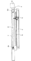
この塗装機は、竿体やゴルフクラブなどの管状体の周面に塗装を施すための機械である。ここでは、管状体の一例としてヘラ竿の竿体Rを例にして説明する。図1及び図2に示すように、この塗装機は、上面を水平面とする台座1と、台座1の上面に竿体Rを水平方向に保持する保持部2と、竿体Rを周方向に回転させる回転機構3と、台座1の上面の長手方向に平行に並んで伸びるレール部4と、レール部4上でレールの長さ方向に移動自在な塗料噴出部5とから構成されている。また、レール部4に並んで塗料噴出部5の下方には長手方向に持上機構6が配置されている。
【0018】
保持部2は、台座1の長手方向両端にそれぞれ配置される一対の受け部2a,2bとからなる。受け部2aは、略円錐型のコーンと、このコーンを受け部2b方向に付勢するコイルバネとから基本的に構成されている。受け部2aはコーンの頭端を他方の受け部2b側に向けており、竿体Rの一端を差し込んだ状態で竿体Rの一端を保持する。受け部2aは長手方向にスライド移動可能にし、且つ任意の場所に固定可能なロック手段を設けておく。また、この受け部2aは周方向に回転自在なものとする。後述のように、竿体Rの周方向回転に伴って回転するためである。
【0019】
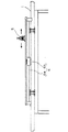
図3〜図5に示すように、他方の受け部2bは、円筒型の本体部10と、本体部10内に収納された円錐状のコーン11と、本体部10内に収納されこのコーン11を受け部2a方向(竿体R側)に付勢するコイルバネ12とから基本的に構成されている。本体部10は一端側の開口に直径方向にバー10aが形成されている。バー10aは本体部10の一端側の開口端面に面一化されており、竿体Rの他端が当接する部分となる。受け部2aによって全体として受け部2b側に付勢されている竿体Rでは、その他端の径に関わらず、竿体Rの他端側端面がバー10aに押しつけられることになる。
【0020】
コーン11は円錐状の頭端を受け部2a方向に向けている。円錐の頭端から底面に至らない位置にまで、上記バー10aに噛み合い得る割りが形成されている。コーン11はこの割りにバー10aを差し込んだ状態で本体部10内に収納される。
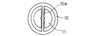
なお、ここではコーンについて割りが一つの直径方向のみに形成されたものを示しているが、図6に示すように、本体部の開口の円に直径方向に2つ相互に直交するようにバー10aを形成し、4つ割りのコーン11を用いることも当然に可能である。4つ割のコーン11を用いる場合、2つの直行するバー10aによりコーン11が案内されるので、コーン11の安定性が向上する。また、バー10aに当接する竿体Rの端面の安定性にも資する。
【0021】
コイルバネ12は、コーン11の底面側に隣接して本体部10内に収納されている。コーン11を頭端側(即ち、受け部2a側)に向かって付勢しており、コーン11は本体部10の軸方向に移動自在となっている。
この受け部2bにおいては、図3及び図5に示すように、竿体Rの他端をコーン11の頭端に差し込んだ状態で、竿体Rを本体部10側に押し込むと、コーン11がコイルバネ12に反して本体部10内に押し込められる。竿体Rの他端はバー10aに当接し、必ずバー10a即ち本体部10の開口端面を基準位置(原点)とする。そして、この竿体Rの他端が原点をとった状態で、コーン11がコイルバネ12により付勢され、竿体Rを保持することになる(図3(b)参照)。
【0022】
保持部2は、このような一対の受け部2aと受け部2bとで竿体Rを挟み込んで、竿体Rを安定した状態で保持している。なお、この一対の受け部2a,2bの間には竿体Rを受け止めて支持する受けローラ20を、一カ所乃至軸方向に間隔を隔てて複数箇所に設けても良い。受けローラ20は、ローラの位置を竿体Rの径に応じて変更するべく上下方向に(竿体Rに対して接離自在に)変更するシリンダに載置されている。この受けローラ20は、保持部2に保持する竿体Rには様々な軸方向長さを有するものがあることから、台座1上を長手方向に任意に移動自在とするのが好ましい。このような受けローラ20を配置することで、先細りテーパの施された軸方向で径の異なる管状体である竿体Rなども安定した状態で保持部2に保持することが可能となる。
【0023】
回転機構3は、竿体Rを周方向に回転させるためのものである。上記一方の受け部2bと受け部2bを回転駆動するモータM(図1等参照)とからなる。上記保持部2の一方の受け部2bは、具体的には、図7に示すように、本体部10に回動軸乃至モータMが順次連結されており、モータMの駆動力が受け部2bに伝達される。モータの回転速度は任意に調整可能となっている。
【0024】
レール部4は、竿体Rに平行に台座1の上面に配置された一対の平行なレールからなる。後述の塗料噴出部5がこの一対のレールに噛み合っており、レール部4の長手方向に沿ってスライド移動する。そして、一対のレール部間に軸方向の位置決め用アクチュエータが配置され、このアクチュエータにより塗料噴出部5の軸方向が決定されることになる。
【0025】
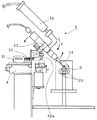
図8に詳しく示すように、塗料噴出部5は、上記レール部4に噛み合って載置されている基体31と、基体31上にレール部4の長手方向に対して直交する面に於いて回動自在に連結されている可動部32と、可動部32上に連結されている塗料タンク33及び塗料タンク33から供給される塗料を噴出する金属製ノズルパイプ34とを有している。また、基体31と可動部32との間にはコイルバネ35が連結されている。
【0026】
基体31は、アクチュエータに連結されレール部4上をその長手方向にスライド移動する部分である。予め基体31乃至塗料噴出部5の軸方向位置をアクチュエータの制御部に入力しておくことで、塗料噴出部5を任意の軸方向位置に位置合わせする。
可動部32は、基体31のレール部4の長手方向に延びる回動軸を介して基体31に連結されておりレール部4に直行する方向に回動する。基体31と可動部32とはコイルバネ35で連結されており、コイルバネ35が基体31側に引き寄せる方向に可動部32を付勢している。コイルバネ35と回動軸を中心として対称な側において、可動部32には金属ノズルパイプ34が配置されており、金属ノズルパイプ34は基本的にX方向(図8参照)に付勢されている。
【0027】
金属ノズルパイプ34は、その内径が0.15〜0.90mm程度、外径が0.40〜1.30mm程度のノズルパイプであり、ある程度の屈曲性が認められる。竿体Rの周面に当接しながら頭端から所定の塗料を噴出する。金属ノズルパイプ34は塗料タンク33に連通しており、塗料タンク33内の塗料が供給されてくる。この塗料タンク33はエアタンク(図示せず)に連結されており、エアタンクからの空気供給量に応じて、塗料タンク33から金属ノズルパイプ34に塗料が必要量だけ供給され、塗料が頭端から噴出される。なお、金属ノズルパイプ34にはさらに独立してエアタンクからの空気の供給を受けており、この独立して供給される空気量によっても、塗料の噴出量が微調整可能である。この際の塗料の塗出圧力は、気温,湿度,塗料の粘度,竿体Rの径等によって任意の調整が要求されるが、例えば、0.3〜0.8Mpa程度に設定する。
【0028】
持上機構6は上記可動部32を回動させるための機構である(図2参照)。具体的には、上記可動部32の下方の台座1上に長手方向に延びる持ち上げバー6aとこの持ち上げバー6aを上下方向に移動させる油圧若しくは気圧シリンダ6bとからなる。図8に示すように、上記可動部32には下方向に持上棒32aが延びている。この持上棒32aは、可動部32のコイルバネ35と回動軸を中心として対称な側にある。そして、持ち上げバー6aが上方向(図8のY方向)に持ち上がると、持ち上げバー6aが持ち上げ棒32aに当てってこれを押し上げ、コイルバネ35に反する方向に可動部32を回動させる。この可動部32の回動によって、金属ノズルパイプ34が竿体Rから離間する。
【0029】
なお、この実施形態の変形例として、コイルバネ35の付勢方向を逆方向として、持上機構6の動作も逆方向とすることも当然に可能である。
次に、この塗装機による、竿体Rに対する段塗り塗装の手順を説明する。
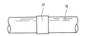
この塗装機によって段塗り塗装を施す竿体Rは、例えば、図9に示すような、ヘラブナ釣り用に用いるヘラ竿を構成する竿体Rである。ヘラ竿を構成する竿体Rは、炭素繊維乃至ガラス繊維などの強化繊維に合成樹脂を含浸させたプリプレグ素材を焼成してなるものである。この竿体Rは外径を天然竹に似せるべく、竹の節の形状や模様等が形成乃至塗装されている。さらに、このような竿体Rの周面に軸方向に間隔を隔てて任意の箇所に段塗り塗装(図9のP部分参照、さらに図10参照)を施すことになる。この段塗り塗装は、竿体Rの周面が部分的に段付きのリング状になるように塗料を肉厚に塗布するものである。詳しくは、通常、竿体Rの周面に必要な下地塗装や一般的な周面塗装を施した後、その周面塗装の上に段塗り塗装を行うことになる。
【0030】
具体的手順を、図12を参照しつつ説明する。
まず、段塗り塗装を施す竿体Rを保持部2に保持させる。詳しくは、一対の受け部2aと受け部2bとが竿体Rの両端を挟み込んで竿体Rを保持する。受け部2aは竿体Rの軸方向長さに合わせて任意の軸方向位置に調整する。受け部2bは、既に説明したように、竿体Rの径に関わらず本体部10の開口面を原点(ゼロ点)として、竿体Rの軸方向位置を決定する。
【0031】
一般に、竿体Rの軸方向の複数の位置に段塗り塗装を施す。このため、段塗り塗装を行う複数の軸方向位置を上記原点(ゼロ点)からの軸方向として、アクチュエータの制御部に入力する(S1)。この際に、個々の段塗り塗装を行う際の塗装幅も入力する。入力後、アクチュエータによって、塗料噴出部5が自動にスタートしレール部4上を移動する(S2)。この軸方向移動時においては、持上機構6によって塗料噴出部5の金属ノズルパイプ34は竿体Rから離間している。
【0032】
上記入力した軸方向位置に塗料噴出部5が至ると、持上機構6のシリンダ6bが下降して持ち上げバー6aも下降し、塗料噴出部5の金属ノズルパイプ34が竿体Rの周面に当接する(S4)。そして、塗料タンク33がエアタンクからの空気供給量に応じて、金属ノズルパイプ34に塗料を供給し、金属ノズルパイプ34が塗料の塗出を開始する(S5)。竿体Rは回転機構3によって回転しており、金属ノズルパイプ34は竿体Rに当接したまま、その周面を荒らし、且つ、塗料を周面に載せて(塗布して)ゆく。既に竿体Rの周面に下塗り塗装などが行われていても、金属ノズルパイプ34がその竿体Rの周面を荒らしながら塗料を塗布するので、塗料が竿体Rの周面に載りやすい。そして、このように金属ノズルパイプ34は竿体Rに当接したまま軸方向に移動し(S6)、一定の幅で塗料を竿体Rの周面に塗布する(図11参照)。
【0033】
この塗料は、エポキシ樹脂塗料とウレタン樹脂塗料とを予め2液混合した塗料を用いるのが好ましい。このような2液混合型の塗料を用いることで比較的厚肉に塗料を竿体R上に塗布し得る。金属ノズルパイプ34の竿体Rに対する当接角度は、竿体の周の接線方向に対し0〜70度程度に設定する。好ましくは30〜60度程度に設定する。竿体Rの回転数は、塗料の噴出量等との関連で任意に調整するべきものであるが、凡そ50〜1000rpm、好ましくは、200〜500rpm程度である。
【0034】
段塗り塗装に必要な軸方向幅だけ移動した金属ノズルパイプ34は、塗料の塗出を終了する(S7)。そして、持上機構6が塗料噴出部5の金属ノズルパイプ34を竿体Rの周面から離間させる。さらに、別の竿体Rの軸方向位置において段塗り塗装を施す場合には、次の塗装開始位置をアクチュエータ制御部が確認し(S8)、その塗装開始位置に塗料噴出部5を移動させる(S3)。塗装予定位置の塗装を全て終えれば、作業を終了する。さらに段塗り塗装を厚肉に行うためには、一度段塗り塗装を竿体Rに施し塗料を乾燥させた後に、再度、同一箇所に段塗り塗装を繰り返してもよい。
【0035】
なお、この実施形態では、管状体として竿体R、特に、ヘラ竿を構成する竿体を用いているが、これに限定されるものではなく、他の様々な管状体に適用することも可能である。
【0036】
【発明の効果】
以上のように、本発明の塗装機によれば、簡易且つ迅速に「段塗り塗装」を竿体周面に行うことができる。熟練した技術を有しない者であっても、容易に段塗り塗装を的確になしえる。
【図面の簡単な説明】
【図1】本発明の実施形態を採用した塗装機の上面図。
【図2】本発明の実施形態を採用した塗装機の正面図。
【図3】保持部2の一方の受け部2bを示した図。
【図4】図3の受け部2bの正面図。
【図5】図3の受け部2bの参考図。
【図6】受け部2bの変形例を示した図。
【図7】受け部2b付近を示した図。
【図8】塗料噴出部5を示した図。
【図9】竿体Rを示した図。
【図10】図9の竿体Rの段塗り塗装部分Pを拡大した図。
【図11】段塗り塗装の状態を示した図。
【図12】本発明の塗装機の作業を示したフローチャート。
【符号の説明】
1 基体
2 保持部
3 回転機構
4 レール部
5 塗料噴出部
6 持上機構[0001]
BACKGROUND OF THE INVENTION
The present invention relates to a coating machine for coating a peripheral surface of a tubular body such as a rod or a golf club constituting a fishing rod.
[0002]
[Prior art]
Many tubular bodies such as rods and golf clubs constituting recent fishing rods are made of carbon fiber reinforced resin or the like in order to reduce weight and maintain strength. Such housings and golf clubs are favorite products, and the peripheral surface is coated for smoothing, decorating, maintaining strength, etc. of the reinforcing fiber portion of the fiber reinforced resin, and further enhancing the design. Various coatings are applied as much as possible.
[0003]
The coating of the peripheral surface of such a tubular body is performed manually by a painter or using a machine, and squeeze coating using a squeeze plate (for example, see Patent Document 1) or spraying is performed. It has been broken. In addition, recently, a method of spraying paint continuously on the peripheral surface of the tubular body by spraying while rotating the tubular body has also been performed (for example, see Patent Document 2).
[0004]
By the way, there is a coating technique called “step coating” as one of the coatings for improving the design of the peripheral surface of such a tubular body. This “step coating” is a coating technique in which the coating is thickly applied in a ring shape while providing a certain thickness on the peripheral surface of the tubular body. This “step coating” is an alternative to traditionally winding a string body around the circumference of a tubular body and applying paint on it to form a ring. The purpose is to decorate the tubular body. Such “step coating” is generally performed by applying paint with a brush at a desired position on the peripheral surface of the cylindrical body while rotating the cylindrical body.
[0005]
[Patent Document 1]
JP-A-8-299884 [0006]
[Patent Document 2]
JP-A-7-79668 [0007]
[Problems to be solved by the invention]
However, in order to perform “step coating” using a brush, a skilled person is required for the painter. That is, it is complicated to apply a desired width at an arbitrary axial position of a tubular body that is long in the axial direction, and it is difficult to maintain a constant coating width over the entire circumferential direction. In addition, “step coating” is a method in which a coating is applied thickly, the coating is applied and dried, and after drying, the thick coating is repeated again, and the work process is also complicated.
[0008]
Furthermore, since “coating” is applied so that it has a certain thickness, if “coating” is performed by spraying as in the past, it is necessary to apply the coating while maintaining a certain thickness. Advanced technology is required, and it is difficult because the paint does not fit well on the periphery of the housing. It also takes time and effort. In addition, the “step coating” may be used for imparting design properties to the tubular body as described above, and may be performed after performing normal peripheral surface coating on the tubular body. For this reason, since further coating is performed on the smoothed peripheral surface coating, “step coating” is particularly difficult.
[0009]
The subject of this invention is providing the coating machine for tubular bodies which can perform "step coating" on a surrounding surface simply and rapidly.
[0010]
[Means for Solving the Problems]
A coating machine according to a first aspect of the present invention is a coating machine for coating a peripheral surface of a tubular body, and a holding portion that holds the tubular body in the horizontal direction and a tubular body held by the holding portion are rotated in the circumferential direction. Rotating means, a rail part arranged in parallel with the holding part, and a paint spraying part movable on the rail part in the length direction of the rail.
[0011]
The paint spraying portion has a paint tank and a nozzle pipe that ejects paint from the paint tank, and the contact state in which the nozzle pipe contacts the circumferential surface of the tubular body, and the separated state in which the nozzle pipe is separated from the circumferential surface of the tubular body It is displaced to.
In this coating machine, a tubular body is disposed in the holding portion in the horizontal direction and held. And the tubular body hold | maintained by the rotation means rotates in the circumferential direction. The paint spraying portion moves on the rail portion to an arbitrary axial position while keeping the separated state, and is brought into a contact state here. And the front-end | tip of the nozzle pipe of a coating material ejection part contact | abuts to a tubular body surrounding surface, and moves the fixed axial direction range, applying the coating material from a coating material tank to a tubular body surrounding surface. While the nozzle pipe is in contact with the circumferential surface of the tubular body and rotating the arbitrary axial position of the tubular body, paint is placed on the circumferential surface of the tubular body at the same time, and a certain axial range of the tubular body is made ring-shaped. Paint.
[0012]
For example, in the case where a coating for undercoating has already been applied to the circumferential surface of the tubular body, the coating is applied while slightly damaging and rubbing the painted surface of the tubular body circumferential surface with this nozzle. The adhesion between the undercoat paint and the paint from the nozzle is also improved. Further, since the nozzle only scratches the part necessary for painting, an extra surface roughening process is not performed, and a beautiful finish is possible.
[0013]
A coating machine according to a second aspect of the present invention is the coating machine according to the first aspect, wherein the coating material ejecting portion is a base that is rotatable on a base placed on the rail part and a surface orthogonal to the longitudinal direction of the rail part. A movable part connected to the upper side, an urging means for urging the movable part in the direction of the tubular body, and a cylinder for pushing the rotating part in the opposite direction are provided. Also, a paint supply means for supplying paint from the nozzle pipe and paint tank to the nozzle pipe is disposed on the movable part.
[0014]
In this coating machine, in the normal state, the movable portion is urged toward the tubular body by the urging means (in a contact state). And the movable part is rotated by pushing the movable part in the anti-tubular body direction with the cylinder, and the coating material ejection part is in the separated state. Further, the paint is supplied from the paint tank to the nozzle pipe by the paint supply means. The amount of paint sprayed from the nozzle pipe can also be adjusted by adjusting the paint supply means.
[0015]
The coating machine according to a third aspect is the coating machine according to the second aspect, further comprising positioning means for changing and positioning the position of the paint spraying portion on the rail portion.
In this coating machine, by inputting necessary information to the positioning means in advance, it becomes possible to easily perform step coating with a certain width at any axial position of the tubular body. A coating machine according to a fourth aspect of the present invention is the coating machine according to any one of the first to third aspects, wherein the holding portion is a contact portion that abuts one end of the tubular body, and the other end of the tubular body is movable in the horizontal direction. And a receiving roller portion disposed between the abutting portion and the moving abutting portion so as to be able to come into contact with and separate from the tubular body.
[0016]
Tubular bodies have various axial lengths, and some have a tapered taper. In this coating machine, one end of the tubular body is brought into contact with the contact portion, and the other is sandwiched between the moving contact portions, and the tubular body having an arbitrary axial length can be held by the holding portion. In addition, since the receiving roller receives the tubular body in the middle in the axial direction, the tubular body can be stably held by the holding portion even when the axial length is long or tapered. .
[0017]
DETAILED DESCRIPTION OF THE INVENTION
Hereinafter, embodiments of the present invention will be described with reference to the drawings.
This coating machine is a machine for coating a peripheral surface of a tubular body such as a housing or a golf club. Here, as an example of the tubular body, a description will be given of a spatula rod body R as an example. As shown in FIGS. 1 and 2, this coating machine includes a pedestal 1 having an upper surface as a horizontal plane, a holding
[0018]
The holding
[0019]
As shown in FIGS. 3 to 5, the other receiving
[0020]
The
In this example, the cone is split only in one diametrical direction, but as shown in FIG. 6, two bars are perpendicular to each other in the diametrical direction to the circle of the opening of the main body. It is of course possible to form 10a and use a quadrant of
[0021]
The
In the receiving
[0022]
The holding
[0023]
The
[0024]
The
[0025]
As shown in detail in FIG. 8, the coating
[0026]
The
The
[0027]
The
[0028]
The
[0029]
As a modified example of this embodiment, it is naturally possible to set the biasing direction of the
Next, the procedure of step coating on the housing R by this coating machine will be described.
The frame R to which step coating is applied by this coating machine is a frame R constituting a spatula rod used for fishing for herbuna as shown in FIG. 9, for example. The casing R constituting the spatula is obtained by firing a prepreg material obtained by impregnating a reinforcing resin such as carbon fiber or glass fiber with a synthetic resin. The frame R is formed or painted with bamboo knot shapes and patterns so that the outer diameter resembles that of natural bamboo. Furthermore, step coating is applied to an arbitrary place on the peripheral surface of such a housing R with an interval in the axial direction (see P portion in FIG. 9 and further FIG. 10). In this step-coating, the coating is applied thickly so that the peripheral surface of the housing R is partially formed into a stepped ring shape. In detail, usually, after applying necessary base coating or general peripheral coating to the peripheral surface of the housing R, step coating is performed on the peripheral coating.
[0030]
A specific procedure will be described with reference to FIG.
First, the housing R to which the step coating is applied is held by the holding
[0031]
In general, step coating is applied to a plurality of axial positions of the housing R. For this reason, a plurality of axial positions where step coating is performed are input to the control unit of the actuator as axial directions from the origin (zero point) (S1). At this time, the painting width when performing individual step coating is also input. After the input, the
[0032]
When the
[0033]
It is preferable to use a paint obtained by mixing two epoxy resin paint and urethane resin paint in advance. By using such a two-component mixed paint, the paint can be applied on the housing R relatively thickly. The contact angle of the
[0034]
The
[0035]
In this embodiment, the casing R, particularly the casing constituting the spatula cage, is used as the tubular body. However, the present invention is not limited to this, and can be applied to various other tubular bodies. It is.
[0036]
【The invention's effect】
As described above, according to the coating machine of the present invention, “step coating” can be performed on the peripheral surface of the housing simply and quickly. Even those who do not have skilled skills can easily perform step coating.
[Brief description of the drawings]
FIG. 1 is a top view of a coating machine adopting an embodiment of the present invention.
FIG. 2 is a front view of a coating machine that employs an embodiment of the present invention.
3 is a view showing one receiving
4 is a front view of the receiving
FIG. 5 is a reference view of the receiving
FIG. 6 is a view showing a modified example of the receiving
FIG. 7 is a view showing the vicinity of a receiving
FIG. 8 is a view showing a
FIG. 9 is a view showing a housing R. FIG.
10 is an enlarged view of a step coating portion P of the casing R in FIG. 9;
FIG. 11 is a diagram showing a state of step coating.
FIG. 12 is a flowchart showing the operation of the coating machine of the present invention.
[Explanation of symbols]
DESCRIPTION OF SYMBOLS 1
Claims (4)
水平方向に前記管状体を保持する保持部と、
前記保持部に保持された管状体を周方向に回転させる回転手段と、
前記保持部に平行に配置されたレール部と、
前記レール部上で前記レールの長さ方向に移動自在な塗料噴出部とを備え、
前記塗料噴出部は塗料タンクと前記塗料タンクからの塗料を噴出するノズルパイプとを有し、前記ノズルパイプが前記管状体周面に当接する当接状態と、前記ノズルパイプが前記管状体周面から離間する離間状態とに変位する、塗装機。A coating machine for coating the peripheral surface of a tubular body,
A holding portion for holding the tubular body in a horizontal direction;
A rotating means for rotating the tubular body held by the holding portion in the circumferential direction;
A rail portion arranged in parallel with the holding portion;
A paint spraying part that is movable in the length direction of the rail on the rail part;
The paint spraying portion includes a paint tank and a nozzle pipe for ejecting paint from the paint tank, the contact state in which the nozzle pipe comes into contact with the tubular body peripheral surface, and the nozzle pipe is in the tubular body peripheral surface Dispensing machine that displaces to a separated state.
前記可動部上に前記ノズルパイプ及び前記塗料タンクから前記金属製ノズルパイプに塗料を供給する塗料供給手段が配置されている、請求項1に記載の塗料機。The paint spraying part includes a base body placed on the rail part, a movable part rotatably connected to the base body in a plane orthogonal to the longitudinal direction of the rail part, and the movable part An urging means for urging the tubular body in the direction of the tubular body and a cylinder for pushing the rotating portion in a direction opposite to the urging means,
The paint machine according to claim 1, wherein a paint supply means for supplying paint from the nozzle pipe and the paint tank to the metal nozzle pipe is disposed on the movable part.
Priority Applications (4)
| Application Number | Priority Date | Filing Date | Title |
|---|---|---|---|
| JP2003077933A JP4261228B2 (en) | 2003-03-20 | 2003-03-20 | Tubular coating machine |
| CNB2004100069889A CN100403891C (en) | 2003-03-20 | 2004-03-03 | Coating machine for tubular body |
| TW093105573A TW200500144A (en) | 2003-03-20 | 2004-03-03 | Device for coating tubular article |
| KR1020040015664A KR101057000B1 (en) | 2003-03-20 | 2004-03-09 | Paint for tubular body |
Applications Claiming Priority (1)
| Application Number | Priority Date | Filing Date | Title |
|---|---|---|---|
| JP2003077933A JP4261228B2 (en) | 2003-03-20 | 2003-03-20 | Tubular coating machine |
Publications (2)
| Publication Number | Publication Date |
|---|---|
| JP2004283702A true JP2004283702A (en) | 2004-10-14 |
| JP4261228B2 JP4261228B2 (en) | 2009-04-30 |
Family
ID=33292563
Family Applications (1)
| Application Number | Title | Priority Date | Filing Date |
|---|---|---|---|
| JP2003077933A Expired - Fee Related JP4261228B2 (en) | 2003-03-20 | 2003-03-20 | Tubular coating machine |
Country Status (4)
| Country | Link |
|---|---|
| JP (1) | JP4261228B2 (en) |
| KR (1) | KR101057000B1 (en) |
| CN (1) | CN100403891C (en) |
| TW (1) | TW200500144A (en) |
Cited By (8)
| Publication number | Priority date | Publication date | Assignee | Title |
|---|---|---|---|---|
| WO2013036185A1 (en) * | 2011-07-22 | 2013-03-14 | Domeij Paer | Device for holding and centering elongated objects during rotational surface treatment |
| CN104785407A (en) * | 2015-05-07 | 2015-07-22 | 深圳市沃尔核材股份有限公司 | Reel core gelatinizing device |
| WO2016105246A1 (en) * | 2014-12-26 | 2016-06-30 | Общество С Ограниченной Ответственностью "Биостэн" (Ооо "Биостэн" | Apparatus for manufacturing thin-walled bodies of revolution |
| JP2017177003A (en) * | 2016-03-30 | 2017-10-05 | 岩城フィルム化工株式会社 | Device for coating rod-shaped body |
| CN109127305A (en) * | 2018-10-09 | 2019-01-04 | 浙江金洲管道工业有限公司 | A kind of outer anti-corrosion drive line of small-caliber steel pipe 3PE |
| CN111482301A (en) * | 2020-04-11 | 2020-08-04 | 宁波润爵科技有限公司 | Painting device for bent lamp post |
| CN112427216A (en) * | 2020-11-05 | 2021-03-02 | 李声启 | Epoxy device is paintd to fishing rod rotation type |
| CN115041343A (en) * | 2022-07-12 | 2022-09-13 | 赣州祺琳新材料有限公司 | BWFRP electric power pipe processing is with spraying equipment |
Families Citing this family (7)
| Publication number | Priority date | Publication date | Assignee | Title |
|---|---|---|---|---|
| CN202490741U (en) * | 2011-10-27 | 2012-10-17 | 金宝电子(中国)有限公司 | Coating device |
| CN104437954A (en) * | 2014-11-10 | 2015-03-25 | 蔡留保 | Fishing rod coloring device |
| CN105537053B (en) * | 2015-12-15 | 2018-03-16 | 江苏金风科技有限公司 | Painting device |
| CN106694302A (en) * | 2017-02-28 | 2017-05-24 | 江苏冠达通电子科技有限公司 | Automatic adhesive-coating device |
| CN109499800A (en) * | 2018-09-27 | 2019-03-22 | 河南新开利泵业有限公司 | Compo pipe production protective coating spray equipment and its application method |
| CN111715437B (en) * | 2020-06-17 | 2021-11-02 | 威海楚创电子科技有限公司 | Automatic auxiliary device for local spray painting of rod body |
| CN115007382B (en) * | 2022-06-29 | 2023-05-23 | 江西浙丰工贸有限公司 | Spraying device for processing steel structure column |
Family Cites Families (4)
| Publication number | Priority date | Publication date | Assignee | Title |
|---|---|---|---|---|
| JPH01107870A (en) * | 1987-10-22 | 1989-04-25 | Toyoda Gosei Co Ltd | Method for spreading rubber cement |
| CN2258433Y (en) * | 1995-12-01 | 1997-07-30 | 大连高新园区兴华铸管科技开发有限公司 | Bitumen spraying coating machine for external surface of casting iron pipe |
| CN2455388Y (en) * | 2000-12-21 | 2001-10-24 | 浙江新嘉联电子有限公司 | Adhesive supplier |
| JP4541604B2 (en) * | 2001-07-30 | 2010-09-08 | Agcテクノグラス株式会社 | Tubular member rotating device |
-
2003
- 2003-03-20 JP JP2003077933A patent/JP4261228B2/en not_active Expired - Fee Related
-
2004
- 2004-03-03 CN CNB2004100069889A patent/CN100403891C/en not_active Expired - Fee Related
- 2004-03-03 TW TW093105573A patent/TW200500144A/en not_active IP Right Cessation
- 2004-03-09 KR KR1020040015664A patent/KR101057000B1/en not_active IP Right Cessation
Cited By (11)
| Publication number | Priority date | Publication date | Assignee | Title |
|---|---|---|---|---|
| WO2013036185A1 (en) * | 2011-07-22 | 2013-03-14 | Domeij Paer | Device for holding and centering elongated objects during rotational surface treatment |
| US9358571B2 (en) | 2011-07-22 | 2016-06-07 | Pär Domeij | Device for holding and centering elongated objects during rotational surface treatment |
| WO2016105246A1 (en) * | 2014-12-26 | 2016-06-30 | Общество С Ограниченной Ответственностью "Биостэн" (Ооо "Биостэн" | Apparatus for manufacturing thin-walled bodies of revolution |
| US10137613B2 (en) | 2014-12-26 | 2018-11-27 | Limited Liability Company “Biosten” (Biosten Llc.) | Apparatus for manufacturing thin-walled bodies of revolution |
| CN104785407A (en) * | 2015-05-07 | 2015-07-22 | 深圳市沃尔核材股份有限公司 | Reel core gelatinizing device |
| JP2017177003A (en) * | 2016-03-30 | 2017-10-05 | 岩城フィルム化工株式会社 | Device for coating rod-shaped body |
| CN109127305A (en) * | 2018-10-09 | 2019-01-04 | 浙江金洲管道工业有限公司 | A kind of outer anti-corrosion drive line of small-caliber steel pipe 3PE |
| CN109127305B (en) * | 2018-10-09 | 2023-09-22 | 浙江金洲管道工业有限公司 | 3PE external anti-corrosion transmission line for small-caliber steel pipe |
| CN111482301A (en) * | 2020-04-11 | 2020-08-04 | 宁波润爵科技有限公司 | Painting device for bent lamp post |
| CN112427216A (en) * | 2020-11-05 | 2021-03-02 | 李声启 | Epoxy device is paintd to fishing rod rotation type |
| CN115041343A (en) * | 2022-07-12 | 2022-09-13 | 赣州祺琳新材料有限公司 | BWFRP electric power pipe processing is with spraying equipment |
Also Published As
| Publication number | Publication date |
|---|---|
| JP4261228B2 (en) | 2009-04-30 |
| TWI320338B (en) | 2010-02-11 |
| TW200500144A (en) | 2005-01-01 |
| CN100403891C (en) | 2008-07-23 |
| KR20040083356A (en) | 2004-10-01 |
| KR101057000B1 (en) | 2011-08-17 |
| CN1531846A (en) | 2004-09-29 |
Similar Documents
| Publication | Publication Date | Title |
|---|---|---|
| JP4261228B2 (en) | Tubular coating machine | |
| US5874016A (en) | Concrete column forming tube having a smooth inside coated surface | |
| CN101407136A (en) | Fingernail colored drawing machine having drying function and fingernail colored drawing method | |
| JP5286971B2 (en) | Cylindrical painting device and painting method | |
| US7707678B2 (en) | Multiple shape changing roller unit | |
| US4946715A (en) | Method for producing faux finishes on non-porous surfaces | |
| JP4614862B2 (en) | Golf club shaft painting method | |
| JP4082675B2 (en) | Tubular body holding device | |
| KR101695312B1 (en) | Automatic painting device | |
| KR20140085319A (en) | Tubular body including decorative layer and method for forming decorative layer on a tubular body | |
| KR101424164B1 (en) | Coating apparatus of stent | |
| JP5224106B2 (en) | Cylindrical inner surface drying device | |
| CN107471843B (en) | Button side pattern making devices | |
| CN209772627U (en) | rolling brush device | |
| JP5812967B2 (en) | Painting gun and painting method | |
| US5340610A (en) | Method of splatter painting a rotating object | |
| JP6442747B2 (en) | Rod-shaped body coating equipment | |
| JP2015213874A (en) | Roller handle | |
| EP4166244A1 (en) | Painting method | |
| CN218167515U (en) | Spraying device is used in production of cosmetics packaging bottle | |
| JPH05316904A (en) | Fishing rod | |
| JP3760613B2 (en) | Coating method and coating gun used therefor | |
| US8936059B2 (en) | Craft bead roller | |
| JP2002171867A (en) | Decorated fishing rod and method for decorating the same | |
| EP4335553A1 (en) | Painting device |
Legal Events
| Date | Code | Title | Description |
|---|---|---|---|
| A521 | Request for written amendment filed |
Free format text: JAPANESE INTERMEDIATE CODE: A821 Effective date: 20060224 |
|
| A621 | Written request for application examination |
Free format text: JAPANESE INTERMEDIATE CODE: A621 Effective date: 20060224 |
|
| RD02 | Notification of acceptance of power of attorney |
Free format text: JAPANESE INTERMEDIATE CODE: A7422 Effective date: 20060224 |
|
| A977 | Report on retrieval |
Free format text: JAPANESE INTERMEDIATE CODE: A971007 Effective date: 20080718 |
|
| A131 | Notification of reasons for refusal |
Free format text: JAPANESE INTERMEDIATE CODE: A131 Effective date: 20080724 |
|
| A521 | Request for written amendment filed |
Free format text: JAPANESE INTERMEDIATE CODE: A523 Effective date: 20080911 |
|
| TRDD | Decision of grant or rejection written | ||
| A01 | Written decision to grant a patent or to grant a registration (utility model) |
Free format text: JAPANESE INTERMEDIATE CODE: A01 Effective date: 20090205 |
|
| A01 | Written decision to grant a patent or to grant a registration (utility model) |
Free format text: JAPANESE INTERMEDIATE CODE: A01 |
|
| A61 | First payment of annual fees (during grant procedure) |
Free format text: JAPANESE INTERMEDIATE CODE: A61 Effective date: 20090205 |
|
| FPAY | Renewal fee payment (event date is renewal date of database) |
Free format text: PAYMENT UNTIL: 20120220 Year of fee payment: 3 |
|
| R150 | Certificate of patent or registration of utility model |
Ref document number: 4261228 Country of ref document: JP Free format text: JAPANESE INTERMEDIATE CODE: R150 Free format text: JAPANESE INTERMEDIATE CODE: R150 |
|
| FPAY | Renewal fee payment (event date is renewal date of database) |
Free format text: PAYMENT UNTIL: 20120220 Year of fee payment: 3 |
|
| FPAY | Renewal fee payment (event date is renewal date of database) |
Free format text: PAYMENT UNTIL: 20130220 Year of fee payment: 4 |
|
| R250 | Receipt of annual fees |
Free format text: JAPANESE INTERMEDIATE CODE: R250 |
|
| FPAY | Renewal fee payment (event date is renewal date of database) |
Free format text: PAYMENT UNTIL: 20140220 Year of fee payment: 5 |
|
| R250 | Receipt of annual fees |
Free format text: JAPANESE INTERMEDIATE CODE: R250 |
|
| R250 | Receipt of annual fees |
Free format text: JAPANESE INTERMEDIATE CODE: R250 |
|
| R250 | Receipt of annual fees |
Free format text: JAPANESE INTERMEDIATE CODE: R250 |
|
| R250 | Receipt of annual fees |
Free format text: JAPANESE INTERMEDIATE CODE: R250 |
|
| R250 | Receipt of annual fees |
Free format text: JAPANESE INTERMEDIATE CODE: R250 |
|
| R250 | Receipt of annual fees |
Free format text: JAPANESE INTERMEDIATE CODE: R250 |
|
| R250 | Receipt of annual fees |
Free format text: JAPANESE INTERMEDIATE CODE: R250 |
|
| R250 | Receipt of annual fees |
Free format text: JAPANESE INTERMEDIATE CODE: R250 |
|
| R250 | Receipt of annual fees |
Free format text: JAPANESE INTERMEDIATE CODE: R250 |
|
| LAPS | Cancellation because of no payment of annual fees |