JP2004278317A - Vehicle deceleration control device - Google Patents
Vehicle deceleration control device Download PDFInfo
- Publication number
- JP2004278317A JP2004278317A JP2003067083A JP2003067083A JP2004278317A JP 2004278317 A JP2004278317 A JP 2004278317A JP 2003067083 A JP2003067083 A JP 2003067083A JP 2003067083 A JP2003067083 A JP 2003067083A JP 2004278317 A JP2004278317 A JP 2004278317A
- Authority
- JP
- Japan
- Prior art keywords
- deceleration
- torque
- engine
- vehicle
- fuel supply
- Prior art date
- Legal status (The legal status is an assumption and is not a legal conclusion. Google has not performed a legal analysis and makes no representation as to the accuracy of the status listed.)
- Granted
Links
Images

Classifications
-
- Y—GENERAL TAGGING OF NEW TECHNOLOGICAL DEVELOPMENTS; GENERAL TAGGING OF CROSS-SECTIONAL TECHNOLOGIES SPANNING OVER SEVERAL SECTIONS OF THE IPC; TECHNICAL SUBJECTS COVERED BY FORMER USPC CROSS-REFERENCE ART COLLECTIONS [XRACs] AND DIGESTS
- Y02—TECHNOLOGIES OR APPLICATIONS FOR MITIGATION OR ADAPTATION AGAINST CLIMATE CHANGE
- Y02A—TECHNOLOGIES FOR ADAPTATION TO CLIMATE CHANGE
- Y02A50/00—TECHNOLOGIES FOR ADAPTATION TO CLIMATE CHANGE in human health protection, e.g. against extreme weather
- Y02A50/20—Air quality improvement or preservation, e.g. vehicle emission control or emission reduction by using catalytic converters
-
- Y—GENERAL TAGGING OF NEW TECHNOLOGICAL DEVELOPMENTS; GENERAL TAGGING OF CROSS-SECTIONAL TECHNOLOGIES SPANNING OVER SEVERAL SECTIONS OF THE IPC; TECHNICAL SUBJECTS COVERED BY FORMER USPC CROSS-REFERENCE ART COLLECTIONS [XRACs] AND DIGESTS
- Y02—TECHNOLOGIES OR APPLICATIONS FOR MITIGATION OR ADAPTATION AGAINST CLIMATE CHANGE
- Y02T—CLIMATE CHANGE MITIGATION TECHNOLOGIES RELATED TO TRANSPORTATION
- Y02T10/00—Road transport of goods or passengers
- Y02T10/60—Other road transportation technologies with climate change mitigation effect
- Y02T10/62—Hybrid vehicles
-
- Y—GENERAL TAGGING OF NEW TECHNOLOGICAL DEVELOPMENTS; GENERAL TAGGING OF CROSS-SECTIONAL TECHNOLOGIES SPANNING OVER SEVERAL SECTIONS OF THE IPC; TECHNICAL SUBJECTS COVERED BY FORMER USPC CROSS-REFERENCE ART COLLECTIONS [XRACs] AND DIGESTS
- Y02—TECHNOLOGIES OR APPLICATIONS FOR MITIGATION OR ADAPTATION AGAINST CLIMATE CHANGE
- Y02T—CLIMATE CHANGE MITIGATION TECHNOLOGIES RELATED TO TRANSPORTATION
- Y02T10/00—Road transport of goods or passengers
- Y02T10/60—Other road transportation technologies with climate change mitigation effect
- Y02T10/7072—Electromobility specific charging systems or methods for batteries, ultracapacitors, supercapacitors or double-layer capacitors
Landscapes
- Electric Propulsion And Braking For Vehicles (AREA)
- Hybrid Electric Vehicles (AREA)
- Exhaust Gas After Treatment (AREA)
- Control Of Vehicle Engines Or Engines For Specific Uses (AREA)
- Electrical Control Of Air Or Fuel Supplied To Internal-Combustion Engine (AREA)
- Combined Controls Of Internal Combustion Engines (AREA)
Abstract
【課題】排気エミッションの低減及び減速性能向上の両立を図ることのできる車両の減速制御装置を提供する。
【解決手段】減速制御装置は、車両の減速が検出されると(タイミングt1)、その検出に応じ燃料カットを行う(タイミングt2)。減速制御装置は前記減速検出(タイミングt1)に応じ、前記燃料カットに先立ちモータジェネレータを発電機として作動させ、その発電に伴う回生制動力によって車両を減速させる。従って、減速前に排気浄化触媒に過剰に酸素が貯蔵されても、タイミングt1〜t2の期間ΔTでの燃焼継続によって、その酸素を消費して、燃料カット後の燃料供給再開時の窒素酸化物の還元に備えることができる。また、上記期間ΔTには燃焼が継続されるため、エンジンのみによって運転者の要求する減速度を実現することが困難であるが、その減速度の不足分を前記回生制動力によって補い、所望の負の加速度Gを得ることができる。
【選択図】 図5A vehicle deceleration control device capable of achieving both reduction of exhaust emission and improvement of deceleration performance is provided.
When a deceleration control of a vehicle is detected (timing t1), a fuel cut is performed in response to the detection (timing t2). The deceleration control device operates the motor generator as a generator prior to the fuel cut in response to the deceleration detection (timing t1), and decelerates the vehicle by a regenerative braking force accompanying the power generation. Therefore, even if oxygen is excessively stored in the exhaust purification catalyst before deceleration, the combustion is continued during the period ΔT between the timings t1 and t2 to consume the oxygen, thereby reducing the nitrogen oxides when the fuel supply is restarted after the fuel cut. For reduction. Further, since combustion is continued during the period ΔT, it is difficult to achieve the deceleration requested by the driver using only the engine. However, the shortage of the deceleration is compensated for by the regenerative braking force, and a desired regenerative braking force is applied. A negative acceleration G can be obtained.
[Selection] Figure 5
Description
【0001】
【発明の属する技術分野】
本発明は車両の減速時に燃料カット及び回生制動を行うようにした車両の減速制御装置に関するものである。
【0002】
【従来の技術】
近年、エンジンと電動機という特性の異なる2種類の動力源を備えたハイブリッド車両が開発・実用化されている。このハイブリッド車両では、前述した2種類の動力源の駆動力を状況に応じて最適に組合わせることで、各動力源の長所を活かし短所を補うようにしている。このため、車両の動力性能を十分に確保しつつ、燃料消費率やエミッション性能の改善を図ることができる。
【0003】
また、上記ハイブリッド車両の一態様として、発電機の機能を兼ね備えた電動機(モータジェネレータ)を用いたものがある。このタイプのハイブリッド車両では、減速時や制動時に駆動輪によってモータジェネレータが回転される。このとき、モータジェネレータが発電機として作動させられ、車両の運動エネルギの一部が電気エネルギに変換されてバッテリに回収(回生)される。この回生に伴い駆動輪に制動力が作用し、車両が減速される。
【0004】
一方、エンジンの出力を必要としない車両の減速時等に、そのエンジンへの燃料供給を停止する、いわゆる燃料カットを行うことにより、不要な燃料消費を抑制して車両の走行燃費を改善する技術が知られている。
【0005】
そして、上記ハイブリッド車両において車両減速中に燃料カットを行うとともに、所定の回生制動力を発生するようにモータジェネレータを制御する技術が提案されている(例えば特許文献1参照)。
【0006】
なお、本発明にかかる先行技術文献としては、特許文献1のほかにも以下に示す特許文献2〜5が挙げられる。
【0007】
【特許文献1】
特開平10−336804号公報
【特許文献2】
特開平10−280990号公報
【特許文献3】
特開平8−88905号公報
【特許文献4】
特開2000−104597号公報
【特許文献5】
特開2000−272381号公報
【0008】
【発明が解決しようとする課題】
ところで、排気通路に排気浄化触媒として、排気中の一酸化炭素CO及び炭化水素HCを酸化するとともに窒素酸化物NOxを還元する、いわゆる三元触媒を設けたエンジンでは、そのエンジンが例えば高回転域で運転されている状態で車両が減速されると、次に示す現象が生ずる。これは、三元触媒が窒素酸化物NOxの還元等に伴う酸素を一時的に貯蔵し、一酸化炭素CO及び炭化水素HCの酸化の際に放出する作用(酸素ストレージ作用)を有することによる。一方、エンジンが高回転域で運転されているときには、エンジンを流れる空気の量が相対的に多くなり、それに伴い三元触媒に貯蔵される酸素の量も多くなる。そのため、燃料カット後、燃料供給が再開されて燃焼が行われた場合に、一酸化炭素CO及び炭化水素HCの酸化は行われるものの窒素酸化物NOxの還元反応が進まない。結果として、窒素酸化物NOxの浄化が十分に行われず、排気エミッションが十分低減されないおそれがある。
【0009】
この点、前述した文献1では、燃料カットに合わせてモータジェネレータに回生制動力を発生させて車両を減速させることについての記載はあるが、排気の浄化についてまでは考慮されていない。そのため、上述した窒素酸化物NOxの浄化についての問題は依然として残る。
【0010】
本発明はこのような実情に鑑みてなされたものであって、その目的は、排気エミッションの低減及び減速性能向上の両立を図ることのできる車両の減速制御装置を提供することにある。
【0011】
【課題を解決するための手段】
以下、上記目的を達成するための手段及びその作用効果について記載する。
請求項1に記載の発明では、車両に搭載され、排気浄化触媒により排気を浄化するようにしたエンジンと、前記車両の車軸に対して回生制動可能に連結された回生制動手段と、前記車両の減速を検出する減速検出手段と、前記減速検出手段による減速の検出に応じ前記エンジンへの燃料供給を停止する燃料供給停止手段とを備える車両の減速制御装置において、前記減速検出手段による減速の検出に応じ、前記燃料供給停止手段による燃料供給停止に先立ち前記回生制動手段にて車両を減速させる減速制御手段をさらに備えている。
【0012】
上記の構成によれば、減速検出手段によって車両の減速が検出されると、まず回生制動手段による車両の減速が行われ、その後にエンジンへの燃料供給が停止される。すなわち、車両の減速が検出された場合、その検出から所定の期間は燃料が供給され続けて燃焼が行われる。このため、例えば減速前のエンジンの運転状態が高回転域にあるときには、排気浄化触媒に蓄えられる酸素の量が多くなるが、この酸素は燃焼継続に伴う排気中の一酸化炭素や炭化水素の酸化に用いられる。排気浄化触媒に貯蔵される酸素の量は、燃料供給停止の直前には車両の減速検出直後よりも少なくなっている。
【0013】
上記期間には燃焼が継続され、その燃焼に伴い発生するエネルギによってエンジンの出力軸が回転されるため、エンジンのみによって車両を減速させて所望の減速度を得ることが困難である。しかし、回生制動手段が車軸の回転によって駆動される。このとき、回生制動手段が発電機として作動させられ、車両の運動エネルギの一部が電気エネルギに変換されて回収される。この発電に伴い発生する回生制動力によって、前述した減速度の不足分が補われる。その結果、車両を所望の減速度で減速させることが可能となる。
【0014】
そして、上記の期間が経過すると、エンジンへの燃料供給が停止され、燃料消費が節減され燃料消費率が向上する。この燃料供給停止に伴いエンジンの出力軸が車軸によって回転されるが、この際、エンジンのフリクショントルク(エンジンの回転に伴う摩擦抵抗)によって制動力が発生するため、車両が減速状態となる。
【0015】
なお、燃料の供給が再開される場合には、前述したように排気浄化触媒に蓄えられた酸素の量が減速前よりも少なくなっているため、減速の検出直後から燃料供給を停止する場合に比べ、窒素酸化物が良好に還元されて浄化される。
【0016】
このように、請求項1に記載の発明によれば、排気エミッションの低減及び減速性能向上の両立を図ることができるようになる。
請求項2に記載の発明では、請求項1に記載の発明において、前記燃料供給停止手段は、前記減速検出手段による減速の検出から所定時間が経過することを条件に前記エンジンへの燃料供給を停止するものであり、前記減速制御手段は、前記減速検出手段による減速の検出から前記燃料供給停止手段による燃料供給停止までの期間に前記回生制動手段にて車両を減速させるものであるとする。
【0017】
上記の構成によれば、減速検出手段による車両の減速検出時を基準として、所定時間が経過するまでは燃料供給停止手段による燃料供給停止が行われない。この期間には回生制動手段の回生制動力によって車両が減速される。そして、前記所定時間が経過したところでエンジンへの燃料供給が停止される。このように、減速の検出後の経過時間に応じて回生制動手段による車両の減速及び燃料の供給停止を行うようにしているので、前述した請求項1に記載の発明の効果を確実なものとすることができる。
【0018】
請求項3に記載の発明では、請求項1又は2に記載の発明において、前記減速制御手段は、前記燃料供給停止手段による燃料の供給から停止への切替えに伴い、同燃料供給停止前よりも前記回生制動手段の回生制動力を小さくするものであるとする。
【0019】
上記の構成によれば、燃料供給停止手段による燃料供給の停止に伴い、エンジンのフリクショントルクによって制動力が発生する。一方、このときには、減速制御手段によって、回生制動手段の制動力が燃料供給停止前よりも小さくされる。このため、エンジンの制動力の増大に伴い、車両全体に作用する制動力が過剰に大きくなるのを抑制することが可能となる。
【0020】
請求項4に記載の発明では、請求項3に記載の発明において、前記減速制御手段は、前記燃料供給停止手段による燃料の供給から停止への切替え直後には前記回生制動手段の回生制動力を徐々に小さくするものであるとする。
【0021】
ここで、エンジンへの燃料供給が行われている状態からその供給が停止された場合、フリクショントルクによるエンジンの制動力が徐々に増加し、所望の大きさになるまでに時間を要する場合があり得る。この点、請求項4に記載の発明では、燃料供給停止への切替え直後には、減速制御手段により回生制動手段の回生制動力が徐々に小さくされる。このため、エンジンの制動力と回生制動手段の回生制動力との総和を、燃料供給停止の前後で略一定にすることができ、運転者の要求に応じた減速度を得てドライバビリティの向上を図ることが可能となる。
【0022】
【発明の実施の形態】
(第1実施形態)
以下、本発明を具体化した第1実施形態について、図1〜図5を参照して説明する。
【0023】
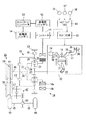
図1に示すように、車両には、動力源としてガソリンエンジン、ディーゼルエンジン等のエンジン(図1はガソリンエンジンを図示)13と、モータジェネレータ(単にモータという場合もある)14とが搭載されている。
【0024】
エンジン13においては、各燃焼室16に吸気通路17を通じて空気が吸入されるとともに、燃料噴射弁18から燃料が噴射供給される。この燃料と空気の混合気に対し点火プラグ19による点火が行われると、その混合気が燃焼してピストン21が往復動し、エンジン13の出力軸であるクランク軸22が回転する。混合気の燃焼により生じた排気は各燃焼室16から排気通路23へ排出され、同排気通路23途中の排気浄化触媒24によって浄化される。排気浄化触媒24としては、排気中の一酸化炭素CO及び炭化水素HCの酸化と、窒素酸化物NOxの還元とを同時に行い、それらを二酸化炭素、水蒸気及び窒素に清浄化する三元触媒が用いられている。
【0025】
エンジン13の出力調整は、吸気通路17に設けられたスロットル弁25をスロットルアクチュエータ26によって駆動して、そのスロットル弁25の開度(スロットル開度)を調節することによって実現される。すなわち、スロットル開度の調整により、エンジン13への吸入空気量が変化し、その変化に対応して燃料噴射量が制御され、燃焼室16に充填される混合気の量が変化してエンジン13の出力が調整される。なお、スロットル開度は、運転者によって操作されるアクセルペダル(図示略)の踏込み量に応じてスロットルアクチュエータ26を駆動することにより調整される。
【0026】
モータジェネレータ14は発電機能を兼ね備えた電動機であり、回生制動手段としても用いられている。モータジェネレータ14は、ロータ14aと、そのロータ14aの周囲に配置されたステータコイル14bとを備えている。このモータジェネレータ14では、ステータコイル14bに通電して、これに与える回転磁界をロータ14aの回転に対して進んだ位相を有するものとすることにより、ロータ14aが回転磁界から連続的に磁力を受けて回転する。すなわち、モータジェネレータ14が電動機として機能する。
【0027】
また、モータジェネレータ14では、ステータコイル14bに与える回転磁界をロータ14aの回転に対して遅延した位相を有するものとすることにより発電が行われる。この際、ステータコイル14bに流される電流が多いほど大きな発電出力が得られる。また、その発電出力を得るために消費される駆動トルクも大きなものとなり、この駆動トルクが回生制動力として作用することになる。
【0028】
これらのエンジン13及びモータジェネレータ14の各動力を個別に、もしくは合成して出力する機構として遊星歯車装置15が用いられている。遊星歯車装置15としては、サンギヤ27、キャリヤ28及びリングギヤ29を回転要素とし、これらの3つの回転要素の間で差動作用を行うようにした、公知のダブルピニオン型が用いられている。サンギヤ27は外歯歯車であり、リングギヤ29はサンギヤ27と同心円上に配置した内歯歯車である。キャリヤ28は、サンギヤ27に噛合する第1ピニオンギヤ31と、同第1ピニオンギヤ31及びリングギヤ29に噛合する第2ピニオンギヤ32とを自転かつ公転自在に保持している。これらの回転要素のうちサンギヤ27にエンジン13のクランク軸22が連結され、キャリヤ28にモータジェネレータ14のロータ14aが連結されている。リングギヤ29とケーシング33との間には、リングギヤ29を選択的に固定するためのブレーキB1が設けられている。
【0029】
遊星歯車装置15には、その出力軸34に対して動力を選択的に伝達するために第1クラッチC1及び第2クラッチC2が設けられている。第1クラッチC1は、キャリヤ28と出力軸34とを選択的に連結するものであり、第2クラッチC2は、リングギヤ29と出力軸34とを選択的に連結するものである。
【0030】
前記出力軸34は変速機35の入力軸36に連結されている。この変速機35は、入力軸36の回転速度と出力軸37の回転速度との比である変速比を変更して駆動トルクを増減するものであり、ここではベルト式の無段変速機が用いられている。このタイプの無段変速機は、溝幅を変更することのできる駆動プーリ38及び従動プーリ39を備えており、両プーリ38,39に対するベルト41の巻き掛け半径を、溝幅の変更により調整して変速比を連続的に変化させるように構成されている。
【0031】
変速機35の出力軸37は複数の歯車群から構成された歯車式動力伝達機構42を介して差動装置43に接続されている。差動装置43には、それぞれ駆動輪44が設けられた左右の車軸45が連結されている。そして、変速機35から歯車式動力伝達機構42を介して差動装置43に伝達された動力は、その差動装置43により左右の車軸45に分配されて駆動輪44に伝達される。
【0032】
さらに、モータジェネレータ14には、インバータ51を介して高電圧バッテリ52が接続されている。インバータ51はスイッチング動作により、高電圧バッテリ52からモータジェネレータ14への電気エネルギの供給を可変にして、モータジェネレータ14の回転速度を可変にする。また、インバータ51は、前記スイッチング動作により、モータジェネレータ14で発電された電力を高電圧バッテリ52に供給する。高電圧バッテリ52は専らモータジェネレータ14を駆動するための電源として用いられ、モータジェネレータ14が発電機として作動しているときには、発電された電力を蓄電する。高電圧バッテリ52には、コンバータの一種であるDC/DCコンバータ53を介して低電圧バッテリ54が接続されている。低電圧バッテリ54は、各種補機(図示略)や、後述するECU61,62等を駆動するための電源として用いられている。DC/DCコンバータ53は、高電圧バッテリ52の電圧を降圧して低電圧バッテリ54に充電する。
【0033】
さらに、車両には、各部の状態を検出するためにクランク角センサ56、アクセルセンサ57、車速センサ58等の各種センサが取付けられている。クランク角センサ56はエンジン13のクランク軸22が一定角度回転する毎に信号を出力する。この信号は、クランク軸22の回転速度であるエンジン回転速度Neの算出に用いられる。アクセルセンサ57は、運転者によるアクセルペダルの踏込み量(アクセル開度)を検出する。車速センサ58は、車両の走行速度である車速を検出する。そして、これらのアクセルセンサ57及び車速センサ58によって、車両の減速を検出する減速検出手段が構成されている。
【0034】
これらのセンサ56〜58の検出値等に基づき、モータジェネレータ14、変速機35等の各部の作動を制御するために、車両にはマイクロコンピュータを中心として構成されたハイブリッド電子制御ユニット(以下「ハイブリッドECU」という)61が設けられている。このハイブリッドECU61では、中央処理装置(CPU)が前記各種センサ56〜58の検出値等に基づき、読出し専用メモリ(ROM)に記憶されている制御プログラムや初期データに従って演算処理を行い、その演算結果に基づいて各種制御を実行する。CPUによる演算結果は、ランダムアクセスメモリ(RAM)において一時的に記憶される。ハイブリッドECU61は、エンジン13の各部の制御を司るエンジン電子制御装置(以下、エンジンECUという)62に通信可能に接続されている。
【0035】
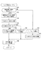
図2のフローチャートは、ハイブリッドECU61が実行する各処理のうち、運転者の要求している車両駆動力(要求トルクT)等を算出等するための「トルク算出ルーチン」を示している。また、図3のフローチャートは、エンジンECU62が実行する各処理のうち、エンジン13のトルクを制御するための「エンジントルク制御ルーチン」を示している。これらのルーチンは所定のタイミング、例えば一定時間毎に繰り返し実行される。これらの処理は、燃料カット(F/C)実行中フラグFに基づいて行われる。燃料カット実行中フラグFは、燃料カットが行われていないときに「オフ」に設定され、行われているときに「オン」に設定される。この燃料カット実行中フラグFの設定は、エンジントルク制御ルーチンにおいて行われる。なお、燃料カット実行中フラグFの「オン」の設定は、エンジンECU62がハイブリッドECU61から燃料カット指令(負の要求エンジントルクTe)を受信した後、所定時間α(例えば1秒)が経過することを条件に行われる。
【0036】
図2のトルク算出ルーチンでは、ハイブリッドECU61はまずステップ100において、予め定められた減速時燃料カット条件が成立しているかどうかを判定する。ここで、減速時燃料カットは、エンジン13の出力を必要としない車両の減速走行時に、そのエンジン13への燃料供給を停止することにより、不要な燃料消費を抑制して車両の走行燃費を改善することを目的として行われる。この減速時燃料カット条件としては、例えば「車両の走行中にアクセルペダルが踏込まれていない(アクセルオフ)こと」が挙げられる。この減速時燃料カット条件が満たされているかどうかを判定するためには、例えば、車速センサ58による車速が所定値(0又はそれに近い値)以上であり、かつアクセルセンサ57によるアクセル開度が所定値(0又はそれに近い値)以下であるかどうかを判定する。このようにして、ステップ100では車両の減速を検出している。
【0037】
上記ステップ100の判定条件が満たされていないと、すなわち運転者に減速の意志がないとステップ160へ移行し、運転者の要求している車両駆動力(要求トルクT)を算出する。この算出に際しては、例えば、車速及びアクセル開度と、要求トルクTとの関係を予め規定した二次元のマップを参照する。このマップでは、例えばアクセル開度が大きくなるに従い、また車速が低くなるに従い要求トルクTが大きくなるような設定がなされている。また、車速が高く、かつアクセル開度が0%のとき、要求トルクTは負の値に設定されている。そして、ステップ160では、車速センサ58による車速、及びアクセルセンサ57によるアクセル開度に対応する要求トルクTを前記マップから割出す。なお、前述したマップに代えて、予め定められた演算式に従って要求トルクTを算出してもよい。
【0038】
続いて、前記要求トルクTのうち、エンジン13の分担分である要求エンジントルクTeと、モータジェネレータ14の分担分である要求モータトルクTmとをそれぞれ算出する。例えば、エンジン13が出力することのできる最大トルクを求め、これを要求エンジントルクTeとする。そのために、例えばエンジン回転速度Ne毎に、エンジン13の出力することのできる最大トルクを予め実験等によって求めておく。そして、クランク角センサ56によって検出されたエンジン回転速度Neを読込み、そのエンジン回転速度Neに対応する最大トルクを割出し、これを要求エンジントルクTeとする。さらに、前述した要求トルクTから前記要求エンジントルクTeを減算し、その減算結果を要求モータトルクTmとする。このようにして、要求エンジントルクTe及び要求モータトルクTmを算出する。
【0039】
次に、ステップ170において、前記ステップ160で求めた要求エンジントルクTeをエンジンECU62に送信する。また、ステップ180において、前記ステップ160で求めた要求モータトルクTmに基づきインバータ51を制御することにより、モータジェネレータ14を電動機として機能させる。この制御によりモータジェネレータ14では、ステータコイル14bにおいてロータ14aの回転に対して進んだ位相を有する回転磁界が発生し、ロータ14aがこの回転磁界から磁力を受けて回転し、要求モータトルクTmに相当するトルクを発生する。そして、このステップ180の処理を経た後に、トルク算出ルーチンを終了する。
【0040】
ところで、前述したステップ100の判定条件が満たされていると、すなわち車両走行中に運転者が減速を意図してアクセルペダルを戻していると、ステップ110において、前述したステップ160と同様にして、車速及びアクセル開度に基づき要求トルクTを求める。この場合、アクセル開度は0%(全閉)であり、求められる要求トルクTは負の値となる。
【0041】
また、ステップ110では、そのときのエンジン13のフリクショントルク(摩擦抵抗トルク)を求め、これを要求エンジントルクTeとする。そのために、例えばエンジン回転速度Ne毎に、エンジン13のフリクショントルクを予め実験等によって求めておく。そして、クランク角センサ56によって検出されたエンジン回転速度Neを読込み、そのエンジン回転速度Neに対応するフリクショントルクを割出し、これを要求エンジントルクTeとする。
【0042】
次に、ステップ120において、前記ステップ110で求めた負の要求エンジントルクTeをエンジンECU62に送信することにより、エンジン13での燃料カットをエンジンECU62に要求する。
【0043】
次に、ステップ130〜150において、前記ステップ110での要求トルクTに基づき要求モータトルクTmを算出する。この際、燃料カット実行中フラグFの状態に応じて要求モータトルクTmの算出の仕方を異ならせている。より詳しくは、ステップ130において、燃料カット実行中フラグFが「オン」であるかどうかを判定する。前述したように、燃料カット実行中フラグFは負の要求エンジントルクTeがエンジンECU62に出力されてから所定時間αが経過するまでは「オフ」であり、経過時に「オン」に切替えられる。
【0044】
上記ステップ130の判定条件が満たされていない(燃料カット実行中フラグFがオフである)と、ステップ140において、要求エンジントルクTeを「0」として、要求モータトルクTmを算出する。要求トルクTから要求エンジントルクTeを減ずることにより要求モータトルクTmを求めることについては先に説明したが、この場合、Te=0であることから、要求トルクTが要求モータトルクTmとなる。要求トルクTが負の値であることから要求モータトルクTmは負の値となる。
【0045】
これに対し、前記ステップ130の判定条件が満たされている(燃料カット実行中フラグFがオンである)と、ステップ150において、前記ステップ110で求めた負の要求エンジントルクTeを用いて、要求モータトルクTmを算出する。すなわち、要求トルクTから要求エンジントルクTeを減算し、その減算結果を要求モータトルクTmとする。この場合、得られる要求モータトルクTmは、前記ステップ140で得られる値よりも大きな値である、「0」又はそれに近い値になる。
【0046】
そして、ステップ140又は150の処理を経た後に、前述したステップ180の処理を行う。ステップ140の処理を経た場合、ステップ180では負の要求モータトルクTmに基づきインバータ51を制御することによりモータジェネレータ14を発電機として機能させる。この制御によりモータジェネレータ14では、ステータコイル14bにおいてロータ14aの回転に対して遅延した位相を有する回転磁界が発生する。ステータコイル14bに流される電流に応じた大きさの発電出力が得られ、高電圧バッテリ52に蓄えられる(回収される)。また、前記発電出力を得るために駆動トルクが消費され、その消費に伴う回生制動力により車両が減速される。
【0047】
一方、ステップ150の処理を経た場合、ステップ180では「0」又はそれに近い要求モータトルクTmに基づきインバータ51を制御する。この制御により、ステータコイル14bに電流が流されなくなるか又は流されても僅かである。
【0048】
上述したトルク算出ルーチンでは、ステップ100,130,140の処理によって減速制御手段が実現される。
次に、エンジンECU62によって行われる「エンジントルク制御ルーチン」について説明する。
【0049】
エンジンECU62はまずステップ210において、ハイブリッドECU61から要求エンジントルクTeを受信したかどうかを判定する。対象となる要求エンジントルクTeは、トルク算出ルーチンのステップ120又は170において送信されたものである。ステップ210の判定条件が満たされていないと、そのままエンジントルク制御ルーチンを終了する。
【0050】
これに対し、ステップ210の判定条件が満たされていると、ステップ220において、要求エンジントルクTeが負の値であるかどうかを判定する。この判定条件が満たされていない(Te≧0)と、すなわち、ハイブリッドECU61が燃料カットを要求していないと、ステップ260において、その要求エンジントルクTeをエンジン13で発生させるべくスロットルアクチュエータ26を駆動制御してスロットル弁25の開度を調整する。この調整により、エンジン13への吸入空気量が変化し、その変化に対応して燃料噴射量が制御され、燃焼室16に充填される混合気の量が変化してエンジン13の出力が調整され、要求エンジントルクTe(Te≧0)に相応するトルクが発生する。続いて、ステップ270において、燃料カット実行中フラグFをオフに切替え、その後、エンジントルク制御ルーチンを一旦終了する。
【0051】
これに対し、ステップ220の判定条件が満たされている(Te<0)と、すなわち、ハイブリッドECU61から燃料カットが要求されていると、ステップ230において、要求エンジントルクTeの受信から所定時間αが経過しているかどうかを判定する。この判定条件が満たされていないと(所定時間α未経過)、そのままエンジントルク制御ルーチンを終了する。従って、所定時間αが経過するまでは、ハイブリッドECU61からは負の要求エンジントルクTeが指令されているにも拘わらず燃料噴射が継続される。換言すると、所定時間αが経過するまでは燃料カットが行われない(燃料カットの開始時期が遅らされる)こととなる。
【0052】
これは、減速前にエンジン13が高回転域で回転していると、排気浄化触媒(三元触媒)24に蓄えられる酸素の量が相対的に多く、この状態で燃料カットが行われた後に燃料供給が再開された場合、窒素酸化物NOxの浄化が進まないおそれがあるからである。そこで、燃料カットを遅らせる(燃料供給を続ける)ことで、一酸化炭素COや炭化水素HCの酸化に酸素を消費して窒素酸化物NOxの浄化を促進しようとしている。
【0053】
一方、ステップ230の判定条件が満たされている(所定時間α経過)と、前記の燃焼により三元触媒での酸素の貯蔵量が少なくなっていると考えられることから、ステップ240において、燃料噴射弁18への通電を停止して、その燃料噴射弁18から燃焼室16への燃料噴射を一時的に停止させる。そして、ステップ250において、燃料カット実行中フラグFを「オン」に設定した後、エンジントルク制御ルーチンの一連の処理を終了する。
【0054】
上述したトルク算出ルーチンにおけるステップ100,110,120と、エンジントルク制御ルーチンにおけるステップ210〜240の処理とによって燃料供給停止手段が実現される。
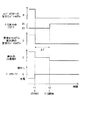
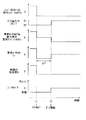
【0055】
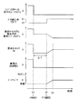
上記トルク算出ルーチン及びエンジントルク制御ルーチンに従って各処理が行われると、要求エンジントルクTe、燃料カット実行中フラグF、車両の加速度G、バッテリパワー等は例えば図5に示すように変化する。図5はタイミングt1でアクセルペダルが戻されて(アクセルオフされて)減速時燃料カット条件が成立し、所定時間αが経過した後のタイミングt2で燃料カットが開始された場合を示している。従って、燃料カット実行中フラグFは、タイミングt2よりも前には「オフ」となり、タイミングt2で「オン」に切替わる。
【0056】
なお、図4は、トルク算出ルーチンのステップ140の処理として、ステップ150と同様の処理を行った場合(比較例)を示している。この場合、燃料カット実行中フラグFに関係なく、ステップ110で求めた要求エンジントルクTe(<0)が要求モータトルクTmの算出に用いられる。
【0057】
この図4では、タイミングt1でアクセルオフされると、要求モータトルクTmの算出(ステップ140)に用いられる要求エンジントルクTeとして、ステップ110で求めた負の値が用いられる。要求トルクTが負であり、要求エンジントルクTeが負であることから、要求トルクTにおける要求モータトルクTmの負担分がないか、もしくは非常に少ない。従って、要求モータトルクTmは「0」又はそれに近い値となる。
【0058】
一方、負の要求エンジントルクTeの送信が開始されるタイミングt1から、所定時間αが経過するタイミングt2までの期間ΔTには燃料カットが行われず、燃料噴射及び燃焼が行われる(ステップ220→230→リターン)。そのため、この期間ΔTにはエンジン13が負担するはずの負のトルク(制動力)が得られない。加えて、この期間ΔTにおいてモータジェネレータ14が発生するトルクは前述したように「0」又はそれに近い値である。エンジン13によってもモータジェネレータ14によっても制動力はほとんど得られない。従って、遊星歯車装置15、変速機35、歯車式動力伝達機構42等を通じて駆動輪44に伝達されるトルク(エンジン13が発生するトルクとモータジェネレータ14が発生するトルクとの総和)は、運転者が要求する負のトルクよりも大きい。走行抵抗以外に車両を減速させる要素がないため、車両の加速度Gは略「0」となり、運転者は期間ΔTに意図する減速感を感ずることができない。また、前記期間ΔTにはモータジェネレータ14で回生発電が行われないのに対し、補機類に電力が供給される(持ち出される)ため、バッテリパワー(電流×電圧)は「0」に近い正側で推移する。
【0059】
そして、タイミングt2以降には負の要求エンジントルクTeに従って燃料カットが行われる(ステップ220→230→240)ため、エンジン13のトルクは負となる。このトルクによって要求トルクTが賄われる。従って、要求モータトルクTmはタイミングt2よりも前と同様に略「0」であるが、駆動輪44に伝達されるトルクは運転者が要求するトルクと略同等となる。車両の加速度Gは負の状態、すなわち減速状態となり、運転者の意図する減速感が得られる。
【0060】
これに対し、第1実施形態ではトルク算出ルーチンにおいて、ステップ140の処理として、要求エンジントルクTeを「0」として要求モータトルクTmの算出に用いている。このように要求エンジントルクTeを「0」とすることで、要求トルクTを実現するためのモータジェネレータ14の担当分を発生させている。この場合、要求トルクTは負であるから、図5に示すように期間ΔTにおける要求モータトルクTmは負の値となる。この負の要求モータトルクTmに基づいてインバータ51が制御されることで、モータジェネレータ14が発電機として作動させられ回生制動力が発生する。発電により得られた電力は高電圧バッテリ52に蓄えられる(回収される)。
【0061】
従って、期間ΔTにはエンジン13において制動力がほとんど発生しないが、その不足分がモータジェネレータ14による回生制動力によって補われることとなる。駆動輪44に伝達されるトルクは、運転者が要求するトルク(要求トルクT)と略同一となる。結果として、車両の加速度Gは負となり、所望の減速感が得られる。
【0062】
なお、タイミングt2以降については、前述した図4と同様である。この場合、負の要求エンジントルクTeに従って燃料カットが行われるため、エンジン13のトルクは負となり、このトルクによって要求トルクTが賄われる。従って、要求モータトルクTmは略「0」となる。駆動輪44に伝達されるトルクは運転者が要求するトルク(要求トルクT)と略同等となる。車両の加速度Gは負となり、運転者が意図する減速感がタイミングt2以降も引き続き得られる。
【0063】
以上詳述した第1実施形態によれば、以下の効果が得られる。
(1)減速時燃料カット条件が成立すると、燃料カットに先立ちモータジェネレータ14によって車両を減速させるようにしている(ステップ100,110,130,140,180)。すなわち、車両の減速を検出しても直ぐに燃料カットを行うのではなく、しばらく燃焼を継続し、所定時間αが経過した後に燃料カットを行うようにしている。このため、例えば減速前のエンジン13の運転状態が高回転域にあるときには、排気浄化触媒24に蓄えられる酸素の量が相対的に多くなるが、燃料継続に伴い生ずる排気中の一酸化炭素COや炭化水素HCの酸化によって酸素を消費して適正量にすることができる。
【0064】
上記減速検出から所定時間αが経過するまでの期間ΔTには、エンジン13では燃焼が引き続き行われ、その燃焼に伴い発生するエネルギによってエンジン13のクランク軸22が回転される。また、変速機35での変速遅れもありエンジン回転速度の低下にある程度の時間を要する。このため、エンジン13のみによって車両を減速させて所望の減速度を得ることが困難である。しかし、モータジェネレータ14のロータ14aが駆動輪44によって回転される。このとき、モータジェネレータ14が発電機として作動させられて、ステータコイル14bに流される電流に応じた大きさの発電出力が得られ、高電圧バッテリ52に蓄えられる(回収される)。また、前記発電出力を得るために駆動トルクが消費され、その消費に伴う回生制動力によって、前述した減速度の不足分が補われる。その結果、車両を所望の減速度で減速させることが可能となり、運転者の意図した車両の減速感を得ることができる。
【0065】
上記の期間ΔTが経過すると燃料カットが行われ、燃料消費が節減され燃料消費率が向上する。この燃料カットに伴いエンジン13が駆動輪44によって駆動されるが、この際、エンジン13のフリクショントルク(エンジン13の回転に伴う摩擦抵抗)によって制動力が発生するため、車両が減速状態となる。
【0066】
なお、燃料カットが終わって燃料供給が再開される場合には、前述したように排気浄化触媒24に蓄えられた酸素の量が減速前よりも少なくなっているため、減速の検出直後から燃料カットを行う場合に比べ、窒素酸化物NOxが良好に還元されて浄化される。
【0067】
このように、第1実施形態によれば排気エミッションの低減及び減速性能向上の両立を図ることができる。
(2)車両の減速が検出されてから所定時間αが経過するまでは燃料供給及び燃焼が継続されるため、エンジン13で発生する制動力は燃料カット時に比べて小さい。従って、仮に要求エンジントルクTeとして、車両の減速検出から所定時間αが経過するまでについても燃料カット時と同様に負の値を用いると、誤った要求モータトルクTmを算出するおそれがある。
【0068】
この点、第1実施形態では、車両の減速検出から燃料カットが行われるまでは、燃料カット時とは異なる態様で要求モータトルクTmを算出するようにしている(ステップ130,140)。すなわち、Te=0として要求モータトルクTmを算出するようにしている。このようにエンジン13の制動力が小さいことを考慮することで、要求モータトルクTmを精度よく求めることが可能となる。モータジェネレータ14によって要求モータトルクTmに相応する回生制動力を発生させて、エンジン13の制動力不足を補い、車両の減速検出から燃料カット開始までの期間ΔTにおいても車両を所望の減速度で減速させることができるようになる。
【0069】
(3)車両の減速を検出した時点を基準として、所定時間αが経過するまでは燃料カットを行わない。この期間にはモータジェネレータ14の回生制動力によって車両を減速させる。そして、所定時間αが経過したところで燃料カットを開始するようにしている。このように、減速の検出後の経過時間に応じてモータジェネレータ14による車両の減速及び燃料カットを行うようにしているので、前述した(1)の効果を確実なものとすることができる。
【0070】
(4)燃料供給から燃料カットへの切替え時には、エンジン13のフリクショントルクによって制動力が発生する。一方、このときには、モータジェネレータ14の回生制動力が燃料カット前よりも小さくされる。このため、エンジン13の制動力の増大に伴い、車両全体に作用する制動力が過剰に大きくなるのを抑制することができる。
【0071】
(5)期間ΔTにおいてモータジェネレータ14を発電機として作動させている(ステップ130,140,180)。このため、燃料カット後の加速時等において、モータジェネレータ14によってエンジン13をアシストする際に備えて充電することができる。回生不足を解消して高電圧バッテリ52の容量の安定化を図ることができる。
【0072】
(第2実施形態)
次に、本発明を具体化した第2実施形態について、図6を参照して説明する。前述した第1実施形態では、図5に示すように、タイミングt2で燃料カットが始まった場合に、エンジン13のフリクショントルクが一気に出ているとして、すなわち、エンジン13のトルクが「0」から負の値に瞬時に切替わっているとして、要求モータトルクTmを算出している。
【0073】
しかし、燃料噴射の行われている状態から燃料カットが行われた場合、フリクショントルクによるエンジン13の制動力が徐々に増加し、所望の大きさになるまでに時間を要する場合があり得る。従って、この所望の大きさになるまでは運転者の要求する減速度が得られないおそれがある。
【0074】
そこで、第2実施形態では、ステップ130の判定条件が満たされた直後(燃料カットが開始されるタイミングt2の直後)から一定の時間が経過するタイミングt3までは、時間の経過に従い要求モータトルク算出用の要求エンジントルクTeを「0」から徐々に小さくしている。これに伴い、タイミングt2〜t3の期間において、要求モータトルクTmが時間の経過に従い徐々に大きくなる。この要求モータトルクTmに基づきインバータ51が制御されることで、モータジェネレータ14の回生制動力が徐々に小さくされる。なお、タイミングt2〜t3の期間においては、バッテリパワーも徐々に増加するため、第1実施形態に比べてバッテリに充電(回収)される電力が増える。
【0075】
従って、第2実施形態によれば前述した(1)〜(5)の効果に加え、次の効果が得られる。
(6)燃料カットの開始直後には、モータジェネレータ14の回生制動力を徐々に小さくしている。このため、エンジン13の制動力とモータジェネレータ14の回生制動力との総和を、燃料カットの前後で略一定にすることができる。車両の減速度を燃料カットの前後で略一定に保つことができ、運転者の要求に応じた減速度を得てドライバビリティの向上を図ることが可能となる。
【0076】
なお、本発明は次に示す別の実施形態に具体化することができる。
・所定時間αは一定の値であってもよいし、条件に応じて異なる値であってもよい。
【0077】
・第2実施形態において、タイミングt2〜t3の期間において要求エンジントルクTeを徐々に減少させるために用いる値、及び要求モータトルクTmを徐々に増加させるために用いられる値を一定の値としてもよいし、また、条件に応じて異ならせてもよい。
【0078】
・トルク算出ルーチンのステップ140における要求エンジントルクTeは「0」に限らず、それに近い値であってもよい。
・アクセルセンサ57に加えて、運転者によるアクセルペダルの踏込みの有無を検出するためのアイドルスイッチを設けてもよい。このアイドルスイッチは、例えばアクセルペダルが踏込まれていない場合にオンとなる。従って、アイドルスイッチがオンされている状態は、運転者が少なくとも車両速度の維持又は加速をしようという意志を有していないことになる。そのため、アイドルスイッチの信号を、前述した減速時燃料カット条件の成否の判定に用いることができる。
【0079】
・変速機35としては、ベルト式の無段変速機以外にも、遊星歯車機構を主体として構成された有段式の変速機や、トロイダル式の無段変速機等の各種の変速機を使用することができる。
【0080】
その他、前記各実施形態から把握できる技術的思想について、それらの効果とともに記載する。
(A)請求項1〜4のいずれかに記載の車両の減速制御装置において、前記回生制動手段は、動力源として前記車両に搭載され、かつ回転機能及び発電機能を兼ね備えるモータジェネレータである。
【0081】
上記の構成によれば、減速時以外にはモータジェネレータを電動機として作動させることで、エンジンのトルクをアシストすることができる。
(B)排気浄化触媒により排気を浄化するとともに、車両の減速検出時にはその検出から所定時間経過後に燃料供給を停止するようにしたエンジンと、
前記車両の車軸に対して回生制動可能に連結された回生制動手段と、
前記車両に要求される要求トルク、及び前記エンジンに要求される要求エンジントルクをそれぞれ求め、両トルクに基づき前記回生制動手段に要求される要求回生制動トルクを求めるトルク算出手段と、
前記要求エンジントルク及び前記要求回生制動トルクが発生するように前記エンジン及び前記回生制動手段の各トルクを制御するトルク制御手段と
を備える車両の減速制御装置であって、
前記トルク算出手段は、前記車両の減速検出から燃料供給停止が行われるまでは、燃料供給停止時とは異なる態様で前記要求回生制動トルクを算出するものであることを特徴とする車両の減速制御装置。
【0082】
ここで、前記両実施形態における要求モータトルクTmが上記要求回生制動トルクに相当する。また、トルク算出ルーチンにおけるステップ110,140,150,160の処理によってトルク算出手段が実現される。トルク算出ルーチンにおけるステップ180の処理とエンジントルク制御ルーチンにおけるステップ260の処理とによってトルク制御手段が実現される。
【0083】
上記の構成によれば、車両の減速が検出されてから所定時間が経過するまでは燃料供給が継続されるため、エンジンで発生する制動力は燃料供給停止時に比べて小さい。従って、仮に要求エンジントルクとして、車両の減速の検出から所定時間が経過するまでについても燃料供給停止時と同様の値を用いると、誤った要求回生制動トルクを算出するおそれがある。
【0084】
この点、上記(B)に記載の発明では、車両の減速検出から燃料供給停止が行われるまでは、燃料供給停止時とは異なる態様で要求回生制動トルクが算出される。従って、エンジンの制動力が小さいことを考慮することで、要求回生制動トルクを精度よく求めることが可能となる。回生制動手段においてこの要求回生制動トルクに相応する回生制動力を発生させることにより、エンジンの制動力不足を補うことが可能となる。その結果、車両の減速検出から燃料供給停止までの期間においても車両を所望の減速度で減速させることができるようになる。
【0085】
(C)上記(B)に記載の車両の減速制御装置において、前記トルク算出手段は、前記要求トルク及び前記要求エンジントルクの偏差を前記要求回生制動トルクとするものである。
【0086】
(D)上記(C)に記載の車両の減速制御装置において、前記トルク算出手段は、前記車両の減速検出から前記燃料供給停止までの期間、前記要求エンジントルクを零として前記要求回生制動トルクを算出するものである。
【0087】
上記の構成によれば、仮に要求エンジントルクとして、車両の減速検出から所定時間が経過するまでについても燃料供給停止時と同様に負の値が用いられると、要求回生制動トルクとして零又はそれに近い値が算出されるおそれがある。
【0088】
この点、上記(D)に記載の発明では、車両の減速検出から燃料供給停止が行われるまでの期間、要求エンジントルクが零とされる。そのため、要求トルク及び要求エンジントルクに基づき算出される要求回生制動トルクは負の値となる。回生制動手段においてこの要求回生制動トルクに相応する回生制動力が発生されると、エンジンの制動力不足が補われ、車両が所望の減速度で減速される。
【図面の簡単な説明】
【図1】本発明の車両の減速制御装置を具体化した第1実施形態についてその構成を示す略図。
【図2】要求トルク等のトルクを算出する手順を示すフローチャート。
【図3】エンジントルクを制御する手順を示すフローチャート。
【図4】アクセルオフ後の期間ΔTに要求エンジントルクTeを負の値として要求モータトルクTmを算出した場合の作用を説明するタイミングチャート。
【図5】アクセルオフ後の期間ΔTに要求エンジントルクTeを「0」として要求モータトルクTmを算出した場合の作用を説明するタイミングチャート。
【図6】燃料カットの開始直後にモータジェネレータの回生制動力を徐々に小さくするようにした第2実施形態について、その作用を説明するタイミングチャート。
【符号の説明】
13…エンジン、14…モータジェネレータ(回生制動手段)、24…排気浄化触媒、45…車軸、57…アクセルセンサ(減速検出手段)、58…車速センサ(減速検出手段)、61…ハイブリッドECU(燃料供給停止手段、減速制御手段)、62…エンジンECU(燃料供給停止手段)、α…所定時間、ΔT…期間。[0001]
TECHNICAL FIELD OF THE INVENTION
The present invention relates to a vehicle deceleration control device that performs fuel cut and regenerative braking when the vehicle decelerates.
[0002]
[Prior art]
In recent years, hybrid vehicles equipped with two types of power sources having different characteristics of an engine and an electric motor have been developed and put into practical use. In this hybrid vehicle, the driving forces of the two types of power sources described above are optimally combined in accordance with the situation, so that the advantages of each power source are used to compensate for the disadvantages. Therefore, it is possible to improve the fuel consumption rate and the emission performance while sufficiently securing the power performance of the vehicle.
[0003]
Further, as one mode of the hybrid vehicle, there is one using an electric motor (motor generator) having a function of a generator. In this type of hybrid vehicle, the motor generator is rotated by the drive wheels during deceleration or braking. At this time, the motor generator is operated as a generator, and a part of the kinetic energy of the vehicle is converted into electric energy and collected (regenerated) by the battery. With this regeneration, a braking force acts on the drive wheels, and the vehicle is decelerated.
[0004]
On the other hand, when the vehicle that does not require the output of the engine is decelerated, the fuel supply to the engine is stopped, that is, a so-called fuel cut is performed, thereby suppressing unnecessary fuel consumption and improving the running fuel efficiency of the vehicle. It has been known.
[0005]
In addition, there has been proposed a technique of performing fuel cut during deceleration of the hybrid vehicle and controlling a motor generator so as to generate a predetermined regenerative braking force (for example, see Patent Document 1).
[0006]
As prior art documents according to the present invention, in addition to
[0007]
[Patent Document 1]
JP-A-10-336804
[Patent Document 2]
JP-A-10-280990
[Patent Document 3]
JP-A-8-88905
[Patent Document 4]
JP-A-2000-104597
[Patent Document 5]
JP 2000-272381 A
[0008]
[Problems to be solved by the invention]
By the way, in an engine provided with a so-called three-way catalyst that oxidizes carbon monoxide CO and hydrocarbons HC in the exhaust gas and reduces nitrogen oxides NOx as an exhaust gas purifying catalyst, the engine is, for example, a high-speed engine. When the vehicle is decelerated in the state where the vehicle is being driven, the following phenomenon occurs. This is because the three-way catalyst has an action (oxygen storage action) of temporarily storing oxygen accompanying the reduction of nitrogen oxides NOx and releasing it during oxidation of carbon monoxide CO and hydrocarbon HC. On the other hand, when the engine is operated in the high rotation range, the amount of air flowing through the engine is relatively large, and accordingly, the amount of oxygen stored in the three-way catalyst is also large. Therefore, when the fuel supply is restarted and the combustion is performed after the fuel cut, the carbon monoxide CO and the hydrocarbon HC are oxidized, but the reduction reaction of the nitrogen oxide NOx does not proceed. As a result, purification of nitrogen oxides NOx may not be sufficiently performed, and exhaust emission may not be sufficiently reduced.
[0009]
In this regard, the above-mentioned
[0010]
The present invention has been made in view of such circumstances, and an object of the present invention is to provide a deceleration control device for a vehicle that can achieve both reduction of exhaust emission and improvement of deceleration performance.
[0011]
[Means for Solving the Problems]
Hereinafter, the means for achieving the above object and the effects thereof will be described.
According to the first aspect of the present invention, an engine mounted on a vehicle and purifying exhaust gas by an exhaust gas purifying catalyst, regenerative braking means connected to an axle of the vehicle so as to be capable of regenerative braking, A deceleration control device for a vehicle, comprising: deceleration detection means for detecting deceleration; and fuel supply stopping means for stopping fuel supply to the engine in response to detection of deceleration by the deceleration detection means. And a deceleration control unit for decelerating the vehicle by the regenerative braking unit before stopping the fuel supply by the fuel supply stopping unit.
[0012]
According to the above configuration, when the deceleration of the vehicle is detected by the deceleration detecting unit, the vehicle is first decelerated by the regenerative braking unit, and thereafter, the fuel supply to the engine is stopped. That is, when deceleration of the vehicle is detected, fuel is continuously supplied for a predetermined period from the detection, and combustion is performed. For this reason, for example, when the operating state of the engine before deceleration is in the high rotation range, the amount of oxygen stored in the exhaust purification catalyst increases. Used for oxidation. The amount of oxygen stored in the exhaust purification catalyst is smaller immediately before the stop of fuel supply than after the detection of deceleration of the vehicle.
[0013]
Since combustion is continued during the above period and the output shaft of the engine is rotated by the energy generated by the combustion, it is difficult to decelerate the vehicle using only the engine to obtain a desired deceleration. However, the regenerative braking means is driven by the rotation of the axle. At this time, the regenerative braking means is operated as a generator, and a part of the kinetic energy of the vehicle is converted into electric energy and collected. The regenerative braking force generated by this power generation compensates for the above-described shortage of deceleration. As a result, the vehicle can be decelerated at a desired deceleration.
[0014]
Then, when the above period elapses, the fuel supply to the engine is stopped, the fuel consumption is reduced, and the fuel consumption rate is improved. When the fuel supply is stopped, the output shaft of the engine is rotated by the axle. At this time, since the braking force is generated by the friction torque of the engine (frictional resistance associated with the rotation of the engine), the vehicle is decelerated.
[0015]
When the fuel supply is restarted, the amount of oxygen stored in the exhaust gas purification catalyst is smaller than before the deceleration as described above. In comparison, nitrogen oxides are favorably reduced and purified.
[0016]
As described above, according to the first aspect of the present invention, it is possible to achieve both reduction of exhaust emission and improvement of deceleration performance.
According to a second aspect of the present invention, in the first aspect of the invention, the fuel supply stopping means supplies the fuel to the engine on condition that a predetermined time has elapsed since the detection of the deceleration by the deceleration detecting means. The vehicle is to be stopped, and the deceleration control unit is configured to decelerate the vehicle by the regenerative braking unit during a period from the detection of deceleration by the deceleration detection unit to the stop of fuel supply by the fuel supply stop unit.
[0017]
According to the above configuration, the fuel supply stop is not performed by the fuel supply stop unit until the predetermined time elapses based on the detection of the vehicle deceleration by the deceleration detector. During this period, the vehicle is decelerated by the regenerative braking force of the regenerative braking means. Then, when the predetermined time has elapsed, the fuel supply to the engine is stopped. As described above, since the vehicle is decelerated and the fuel supply is stopped by the regenerative braking means in accordance with the elapsed time after the detection of the deceleration, the effect of the invention described in
[0018]
According to the invention described in claim 3, in the invention described in
[0019]
According to the above configuration, when the fuel supply is stopped by the fuel supply stopping means, a braking force is generated by the friction torque of the engine. On the other hand, at this time, the braking force of the regenerative braking means is made smaller by the deceleration control means than before the fuel supply was stopped. For this reason, it is possible to prevent the braking force acting on the entire vehicle from becoming excessively large as the engine braking force increases.
[0020]
According to a fourth aspect of the present invention, in the third aspect of the present invention, the deceleration control unit controls the regenerative braking force of the regenerative braking unit immediately after switching from fuel supply to stop by the fuel supply stopping unit. It is assumed that the size is gradually reduced.
[0021]
Here, when the supply of fuel to the engine is stopped from the state in which it is being supplied, the braking force of the engine due to the friction torque gradually increases, and it may take time until the engine reaches a desired magnitude. obtain. In this regard, in the invention according to the fourth aspect, immediately after switching to the stop of fuel supply, the regenerative braking force of the regenerative braking means is gradually reduced by the deceleration control means. For this reason, the sum of the braking force of the engine and the regenerative braking force of the regenerative braking means can be made substantially constant before and after the fuel supply is stopped, and the deceleration according to the driver's request is obtained to improve drivability. Can be achieved.
[0022]
DETAILED DESCRIPTION OF THE INVENTION
(First embodiment)
Hereinafter, a first embodiment of the present invention will be described with reference to FIGS.
[0023]
As shown in FIG. 1, a vehicle is equipped with an engine (a gasoline engine is shown in FIG. 1) 13 such as a gasoline engine or a diesel engine as a power source, and a motor generator (sometimes simply called a motor) 14. I have.
[0024]
In the
[0025]
The output of the
[0026]
The
[0027]
Further, in the
[0028]
A
[0029]
The
[0030]
The
[0031]
The
[0032]
Further,
[0033]
Further, various sensors such as a
[0034]
In order to control the operation of each unit such as the
[0035]
The flowchart of FIG. 2 shows a “torque calculation routine” for calculating, for example, a vehicle driving force (requested torque T) requested by the driver among the processes executed by the
[0036]
In the torque calculation routine of FIG. 2, first, in
[0037]
If the determination condition of
[0038]
Subsequently, of the required torque T, a required engine torque Te, which is an allotment of the
[0039]
Next, at
[0040]
By the way, if the above-described determination condition of
[0041]
In
[0042]
Next, in
[0043]
Next, in
[0044]
If the determination condition in
[0045]
On the other hand, if the determination condition of the
[0046]
Then, after the processing of
[0047]
On the other hand, after the processing in
[0048]
In the above-described torque calculation routine, the processing in
Next, an “engine torque control routine” performed by the
[0049]
First, at
[0050]
On the other hand, if the determination condition in
[0051]
On the other hand, if the determination condition of
[0052]
This is because if the
[0053]
On the other hand, if the determination condition of
[0054]
The fuel supply stopping means is realized by the processing of
[0055]
When each process is performed in accordance with the above-described torque calculation routine and engine torque control routine, the required engine torque Te, the fuel cut execution flag F, the vehicle acceleration G, the battery power, and the like change as shown in FIG. 5, for example. FIG. 5 shows a case in which the accelerator pedal is returned (accelerator is turned off) at timing t1, the deceleration fuel cut condition is satisfied, and the fuel cut is started at timing t2 after a predetermined time α has elapsed. Therefore, the fuel cut execution flag F is turned "off" before the timing t2, and is switched to "on" at the timing t2.
[0056]
FIG. 4 shows a case where the same processing as in
[0057]
In FIG. 4, when the accelerator is turned off at timing t1, the negative value obtained in
[0058]
On the other hand, during the period ΔT from the timing t1 at which the transmission of the negative required engine torque Te is started to the timing t2 at which the predetermined time α elapses, the fuel cut is not performed, and the fuel injection and combustion are performed (
[0059]
Then, after the timing t2, the fuel cut is performed according to the negative required engine torque Te (
[0060]
On the other hand, in the first embodiment, in the torque calculation routine, the required engine torque Te is set to “0” and used in the calculation of the required motor torque Tm as the processing of
[0061]
Therefore, during the period ΔT, almost no braking force is generated in the
[0062]
Note that the operation after timing t2 is the same as in FIG. 4 described above. In this case, since the fuel cut is performed according to the negative required engine torque Te, the torque of the
[0063]
According to the first embodiment described in detail above, the following effects can be obtained.
(1) When the deceleration fuel cut condition is satisfied, the vehicle is decelerated by the
[0064]
During the period ΔT from the detection of the deceleration to the elapse of the predetermined time α, combustion continues in the
[0065]
After the elapse of the period ΔT, a fuel cut is performed, fuel consumption is reduced, and the fuel consumption rate is improved. The
[0066]
When the fuel supply is restarted after the fuel cut, the amount of oxygen stored in the
[0067]
As described above, according to the first embodiment, it is possible to achieve both reduction of the exhaust emission and improvement of the deceleration performance.
(2) Since the fuel supply and the combustion are continued until a predetermined time α elapses after the detection of the deceleration of the vehicle, the braking force generated by the
[0068]
In this regard, in the first embodiment, the required motor torque Tm is calculated in a manner different from that at the time of fuel cut from detection of deceleration of the vehicle until fuel cut is performed (
[0069]
(3) The fuel cut is not performed until a predetermined time α elapses based on the time point when the deceleration of the vehicle is detected. During this period, the vehicle is decelerated by the regenerative braking force of
[0070]
(4) At the time of switching from fuel supply to fuel cut, a braking force is generated by the friction torque of the
[0071]
(5) In the period ΔT, the
[0072]
(Second Embodiment)
Next, a second embodiment of the present invention will be described with reference to FIG. In the above-described first embodiment, as shown in FIG. 5, when the fuel cut starts at timing t2, it is assumed that the friction torque of the
[0073]
However, when the fuel cut is performed from the state where the fuel injection is being performed, the braking force of the
[0074]
Therefore, in the second embodiment, the required motor torque calculation is performed in accordance with the lapse of time from the time immediately after the determination condition of
[0075]
Therefore, according to the second embodiment, the following effects can be obtained in addition to the effects (1) to (5) described above.
(6) Immediately after the start of the fuel cut, the regenerative braking force of the
[0076]
Note that the present invention can be embodied in another embodiment described below.
The predetermined time α may be a constant value or a different value depending on conditions.
[0077]
In the second embodiment, the value used for gradually decreasing the required engine torque Te and the value used for gradually increasing the required motor torque Tm during the period from the timing t2 to the timing t3 may be constant. However, it may be made different depending on conditions.
[0078]
The required engine torque Te in
-In addition to the
[0079]
As the
[0080]
In addition, technical ideas that can be grasped from the above embodiments will be described together with their effects.
(A) In the vehicle deceleration control device according to any one of
[0081]
According to the above configuration, the torque of the engine can be assisted by operating the motor generator as an electric motor except during deceleration.
(B) an engine that purifies exhaust gas by an exhaust gas purifying catalyst and stops fuel supply after a lapse of a predetermined time from detection of vehicle deceleration.
Regenerative braking means connected regeneratively to the axle of the vehicle,
A torque calculating unit that calculates a required torque required for the vehicle and a required engine torque required for the engine, and calculates a required regenerative braking torque required for the regenerative braking unit based on the two torques;
Torque control means for controlling each torque of the engine and the regenerative braking means so that the required engine torque and the required regenerative braking torque are generated; and
A deceleration control device for a vehicle comprising:
The deceleration control of the vehicle, wherein the torque calculation means calculates the required regenerative braking torque in a mode different from that at the time of stopping the fuel supply from the detection of the deceleration of the vehicle until the fuel supply is stopped. apparatus.
[0082]
Here, the required motor torque Tm in both embodiments corresponds to the required regenerative braking torque. Further, a torque calculation unit is realized by the processing of
[0083]
According to the above configuration, the fuel supply is continued until a predetermined time elapses after the detection of the deceleration of the vehicle, so that the braking force generated by the engine is smaller than when the fuel supply is stopped. Therefore, if the same value as that at the time of stopping the fuel supply is used as the required engine torque until the predetermined time elapses from the detection of the deceleration of the vehicle, an erroneous required regenerative braking torque may be calculated.
[0084]
In this regard, in the invention described in the above (B), the required regenerative braking torque is calculated in a different manner from when the fuel supply is stopped until the fuel supply is stopped after the vehicle deceleration is detected. Therefore, the required regenerative braking torque can be accurately obtained by considering that the braking force of the engine is small. By generating the regenerative braking force corresponding to the required regenerative braking torque in the regenerative braking means, it becomes possible to compensate for the insufficient braking force of the engine. As a result, the vehicle can be decelerated at the desired deceleration even during the period from the detection of deceleration of the vehicle to the stop of fuel supply.
[0085]
(C) In the vehicle deceleration control device according to (B), the torque calculation means sets a deviation between the required torque and the required engine torque as the required regenerative braking torque.
[0086]
(D) In the vehicle deceleration control device according to (C), the torque calculation unit sets the required engine torque to zero during the period from the detection of the vehicle deceleration to the stop of the fuel supply to reduce the required regenerative braking torque. It is to be calculated.
[0087]
According to the above configuration, if a negative value is used as the required engine torque in the same manner as when the fuel supply is stopped until the predetermined time elapses from the detection of the deceleration of the vehicle, the required regenerative braking torque is zero or close thereto. The value may be calculated.
[0088]
In this regard, in the invention described in the above (D), the required engine torque is set to zero during the period from the detection of the deceleration of the vehicle to the stop of the fuel supply. Therefore, the required regenerative braking torque calculated based on the required torque and the required engine torque has a negative value. When the regenerative braking means generates a regenerative braking force corresponding to the required regenerative braking torque, the shortage of the braking force of the engine is compensated, and the vehicle is decelerated at a desired deceleration.
[Brief description of the drawings]
FIG. 1 is a schematic diagram showing a configuration of a first embodiment embodying a vehicle deceleration control device of the present invention.
FIG. 2 is a flowchart showing a procedure for calculating a torque such as a required torque.
FIG. 3 is a flowchart showing a procedure for controlling engine torque.
FIG. 4 is a timing chart for explaining the operation when the required motor torque Tm is calculated during a period ΔT after the accelerator is turned off, with the required engine torque Te being a negative value.
FIG. 5 is a timing chart illustrating an operation when a required motor torque Tm is calculated by setting a required engine torque Te to “0” during a period ΔT after the accelerator is turned off.
FIG. 6 is a timing chart illustrating the operation of the second embodiment in which the regenerative braking force of the motor generator is gradually reduced immediately after the start of the fuel cut.
[Explanation of symbols]
13 ... Engine, 14 ... Motor generator (regenerative braking means), 24 ... Exhaust purification catalyst, 45 ... Axle, 57 ... Accelerator sensor (Deceleration detecting means), 58 ... Vehicle speed sensor (Deceleration detecting means), 61 ... Hybrid ECU (Fuel) Supply stop means, deceleration control means), 62: engine ECU (fuel supply stop means), α: predetermined time, ΔT: period.
Claims (4)
前記車両の車軸に対して回生制動可能に連結された回生制動手段と、
前記車両の減速を検出する減速検出手段と、
前記減速検出手段による減速の検出に応じ前記エンジンへの燃料供給を停止する燃料供給停止手段と
を備える車両の減速制御装置において、
前記減速検出手段による減速の検出に応じ、前記燃料供給停止手段による燃料供給停止に先立ち前記回生制動手段にて車両を減速させる減速制御手段をさらに備えることを特徴とする車両の減速制御装置。An engine mounted on the vehicle and purifying exhaust gas by an exhaust gas purifying catalyst;
Regenerative braking means connected regeneratively to the axle of the vehicle,
Deceleration detection means for detecting deceleration of the vehicle,
Fuel supply stopping means for stopping fuel supply to the engine in response to the detection of deceleration by the deceleration detecting means,
A deceleration control device for a vehicle, further comprising deceleration control means for decelerating the vehicle by the regenerative braking means prior to stopping fuel supply by the fuel supply stop means in response to detection of deceleration by the deceleration detection means.
前記減速制御手段は、前記減速検出手段による減速の検出から前記燃料供給停止手段による燃料供給停止までの期間に前記回生制動手段にて車両を減速させるものである請求項1に記載の車両の減速制御装置。The fuel supply stopping unit stops the fuel supply to the engine on condition that a predetermined time has elapsed from the detection of the deceleration by the deceleration detecting unit.
2. The vehicle according to claim 1, wherein the deceleration control unit decelerates the vehicle by the regenerative braking unit during a period from the detection of deceleration by the deceleration detection unit to the stop of fuel supply by the fuel supply stop unit. 3. Control device.
Priority Applications (1)
| Application Number | Priority Date | Filing Date | Title |
|---|---|---|---|
| JP2003067083A JP3891130B2 (en) | 2003-03-12 | 2003-03-12 | Vehicle deceleration control device |
Applications Claiming Priority (1)
| Application Number | Priority Date | Filing Date | Title |
|---|---|---|---|
| JP2003067083A JP3891130B2 (en) | 2003-03-12 | 2003-03-12 | Vehicle deceleration control device |
Publications (2)
| Publication Number | Publication Date |
|---|---|
| JP2004278317A true JP2004278317A (en) | 2004-10-07 |
| JP3891130B2 JP3891130B2 (en) | 2007-03-14 |
Family
ID=33284799
Family Applications (1)
| Application Number | Title | Priority Date | Filing Date |
|---|---|---|---|
| JP2003067083A Expired - Lifetime JP3891130B2 (en) | 2003-03-12 | 2003-03-12 | Vehicle deceleration control device |
Country Status (1)
| Country | Link |
|---|---|
| JP (1) | JP3891130B2 (en) |
Cited By (9)
| Publication number | Priority date | Publication date | Assignee | Title |
|---|---|---|---|---|
| WO2006137591A1 (en) * | 2005-06-22 | 2006-12-28 | Toyota Jidosha Kabushiki Kaisha | Controller of drive device for vehicle |
| JP2007001491A (en) * | 2005-06-24 | 2007-01-11 | Toyota Motor Corp | Control device for vehicle drive device |
| JP2007315447A (en) * | 2006-05-24 | 2007-12-06 | Toyota Motor Corp | VEHICLE POWER DEVICE AND CONTROL DEVICE THEREOF |
| JP2010195157A (en) * | 2009-02-24 | 2010-09-09 | Toyota Motor Corp | Hybrid car and method for controlling the same |
| US8038571B2 (en) | 2005-06-22 | 2011-10-18 | Toyota Jidosha Kabushiki Kaisha | Control device for vehicular drive apparatus |
| US20130197765A1 (en) * | 2010-08-09 | 2013-08-01 | Matthias Schmidt | Method for operating a vehicle electrical system, a controller and a computer program product |
| JP2018024392A (en) * | 2016-08-12 | 2018-02-15 | 株式会社Subaru | Vehicle control device |
| WO2020026621A1 (en) * | 2018-08-02 | 2020-02-06 | ボッシュ株式会社 | Vehicle control device |
| US10919600B2 (en) | 2017-09-25 | 2021-02-16 | Taiyo Yuden Co., Ltd. | Motor driving control apparatus and method and motor-assisted vehicle |
-
2003
- 2003-03-12 JP JP2003067083A patent/JP3891130B2/en not_active Expired - Lifetime
Cited By (14)
| Publication number | Priority date | Publication date | Assignee | Title |
|---|---|---|---|---|
| WO2006137591A1 (en) * | 2005-06-22 | 2006-12-28 | Toyota Jidosha Kabushiki Kaisha | Controller of drive device for vehicle |
| US8038571B2 (en) | 2005-06-22 | 2011-10-18 | Toyota Jidosha Kabushiki Kaisha | Control device for vehicular drive apparatus |
| JP2007001491A (en) * | 2005-06-24 | 2007-01-11 | Toyota Motor Corp | Control device for vehicle drive device |
| JP2007315447A (en) * | 2006-05-24 | 2007-12-06 | Toyota Motor Corp | VEHICLE POWER DEVICE AND CONTROL DEVICE THEREOF |
| JP2010195157A (en) * | 2009-02-24 | 2010-09-09 | Toyota Motor Corp | Hybrid car and method for controlling the same |
| US8996216B2 (en) * | 2010-08-09 | 2015-03-31 | Robert Bosch Gmbh | Method for operating a vehicle electrical system, a controller and a computer program product |
| US20130197765A1 (en) * | 2010-08-09 | 2013-08-01 | Matthias Schmidt | Method for operating a vehicle electrical system, a controller and a computer program product |
| JP2018024392A (en) * | 2016-08-12 | 2018-02-15 | 株式会社Subaru | Vehicle control device |
| US10919600B2 (en) | 2017-09-25 | 2021-02-16 | Taiyo Yuden Co., Ltd. | Motor driving control apparatus and method and motor-assisted vehicle |
| WO2020026621A1 (en) * | 2018-08-02 | 2020-02-06 | ボッシュ株式会社 | Vehicle control device |
| CN112752688A (en) * | 2018-08-02 | 2021-05-04 | 博世株式会社 | Vehicle control device |
| JPWO2020026621A1 (en) * | 2018-08-02 | 2021-08-05 | ボッシュ株式会社 | Vehicle control device |
| JP7223762B2 (en) | 2018-08-02 | 2023-02-16 | ボッシュ株式会社 | vehicle controller |
| CN112752688B (en) * | 2018-08-02 | 2024-01-30 | 博世株式会社 | Vehicle control device |
Also Published As
| Publication number | Publication date |
|---|---|
| JP3891130B2 (en) | 2007-03-14 |
Similar Documents
| Publication | Publication Date | Title |
|---|---|---|
| CN101356088B (en) | Hybrid vehicle and its control method | |
| CN101646587B (en) | Vehicle and control method thereof | |
| JP4321520B2 (en) | POWER OUTPUT DEVICE, VEHICLE MOUNTING THE SAME, AND METHOD FOR CONTROLLING POWER OUTPUT DEVICE | |
| JP4474293B2 (en) | Hybrid vehicle and control method thereof | |
| JPH08232817A (en) | Hybrid vehicle | |
| JP4513751B2 (en) | Hybrid vehicle and control method thereof | |
| JP2014159255A (en) | Control device for hybrid vehicle | |
| JPH10288028A (en) | Operation control device for hybrid vehicle | |
| JP5288984B2 (en) | Hybrid vehicle | |
| JP3601508B2 (en) | Hybrid vehicle with stepped transmission | |
| JP3891130B2 (en) | Vehicle deceleration control device | |
| JP2005320941A (en) | Power output apparatus, automobile equipped with the same, and control method of power output apparatus | |
| JP2007307995A (en) | Hybrid vehicle control device and hybrid vehicle control method. | |
| JP2007204004A (en) | Vehicle deceleration control device | |
| JP4811323B2 (en) | Vehicle and control method thereof | |
| JP3370265B2 (en) | Hybrid vehicle | |
| JP2013224078A (en) | Hybrid vehicle | |
| JP2010090730A (en) | Temperature control apparatus for exhaust emission control catalyst | |
| JP3909695B2 (en) | Vehicle control device | |
| JP2010132074A (en) | Controller for hybrid vehicle | |
| JP2005341644A (en) | Control device for hybrid vehicle | |
| JP2011235809A (en) | Device and method for controlling vehicles | |
| JP3350520B2 (en) | Hybrid vehicle | |
| JP5239809B2 (en) | Vehicle control apparatus and control method | |
| JP2021133692A (en) | Vehicular rotation speed control apparatus |
Legal Events
| Date | Code | Title | Description |
|---|---|---|---|
| A621 | Written request for application examination |
Free format text: JAPANESE INTERMEDIATE CODE: A621 Effective date: 20060116 |
|
| A131 | Notification of reasons for refusal |
Free format text: JAPANESE INTERMEDIATE CODE: A131 Effective date: 20060314 |
|
| A521 | Request for written amendment filed |
Free format text: JAPANESE INTERMEDIATE CODE: A523 Effective date: 20060512 |
|
| A02 | Decision of refusal |
Free format text: JAPANESE INTERMEDIATE CODE: A02 Effective date: 20060801 |
|
| A521 | Request for written amendment filed |
Free format text: JAPANESE INTERMEDIATE CODE: A523 Effective date: 20060830 |
|
| A911 | Transfer to examiner for re-examination before appeal (zenchi) |
Free format text: JAPANESE INTERMEDIATE CODE: A911 Effective date: 20061005 |
|
| TRDD | Decision of grant or rejection written | ||
| A01 | Written decision to grant a patent or to grant a registration (utility model) |
Free format text: JAPANESE INTERMEDIATE CODE: A01 Effective date: 20061114 |
|
| A61 | First payment of annual fees (during grant procedure) |
Free format text: JAPANESE INTERMEDIATE CODE: A61 Effective date: 20061127 |
|
| R151 | Written notification of patent or utility model registration |
Ref document number: 3891130 Country of ref document: JP Free format text: JAPANESE INTERMEDIATE CODE: R151 |
|
| FPAY | Renewal fee payment (event date is renewal date of database) |
Free format text: PAYMENT UNTIL: 20101215 Year of fee payment: 4 |
|
| FPAY | Renewal fee payment (event date is renewal date of database) |
Free format text: PAYMENT UNTIL: 20101215 Year of fee payment: 4 |
|
| FPAY | Renewal fee payment (event date is renewal date of database) |
Free format text: PAYMENT UNTIL: 20111215 Year of fee payment: 5 |
|
| FPAY | Renewal fee payment (event date is renewal date of database) |
Free format text: PAYMENT UNTIL: 20111215 Year of fee payment: 5 |
|
| FPAY | Renewal fee payment (event date is renewal date of database) |
Free format text: PAYMENT UNTIL: 20121215 Year of fee payment: 6 |
|
| FPAY | Renewal fee payment (event date is renewal date of database) |
Free format text: PAYMENT UNTIL: 20131215 Year of fee payment: 7 |
|
| EXPY | Cancellation because of completion of term |