JP2004269244A - Control device of elevator - Google Patents
Control device of elevator Download PDFInfo
- Publication number
- JP2004269244A JP2004269244A JP2003066400A JP2003066400A JP2004269244A JP 2004269244 A JP2004269244 A JP 2004269244A JP 2003066400 A JP2003066400 A JP 2003066400A JP 2003066400 A JP2003066400 A JP 2003066400A JP 2004269244 A JP2004269244 A JP 2004269244A
- Authority
- JP
- Japan
- Prior art keywords
- heating element
- duct
- panel case
- control panel
- elevator
- Prior art date
- Legal status (The legal status is an assumption and is not a legal conclusion. Google has not performed a legal analysis and makes no representation as to the accuracy of the status listed.)
- Pending
Links
- 238000010438 heat treatment Methods 0.000 claims abstract description 90
- 238000001816 cooling Methods 0.000 claims abstract description 54
- 229910052751 metal Inorganic materials 0.000 claims description 6
- 239000002184 metal Substances 0.000 claims description 6
- 230000000149 penetrating effect Effects 0.000 claims description 6
- 239000011148 porous material Substances 0.000 claims 1
- 230000005855 radiation Effects 0.000 description 7
- 238000009423 ventilation Methods 0.000 description 6
- 229910052782 aluminium Inorganic materials 0.000 description 2
- XAGFODPZIPBFFR-UHFFFAOYSA-N aluminium Chemical compound [Al] XAGFODPZIPBFFR-UHFFFAOYSA-N 0.000 description 2
- 230000007423 decrease Effects 0.000 description 1
- 238000007599 discharging Methods 0.000 description 1
- 230000000694 effects Effects 0.000 description 1
- 238000012423 maintenance Methods 0.000 description 1
- 230000003068 static effect Effects 0.000 description 1
- 238000011144 upstream manufacturing Methods 0.000 description 1
Images


Landscapes
- Elevator Control (AREA)
- Patch Boards (AREA)
Abstract
Description
【0001】
【発明の属する技術分野】
この発明は、制御盤用ケースと、この制御盤用ケース内に設けられエレベータの運転を制御する電気部品である発熱体と、この発熱体を冷却する冷却用ファンと、この冷却用ファンにより流れる空気を発熱体に導くダクトとを備えたエレベータの制御装置に関するものである。
【0002】
【従来の技術】
従来、エレベータの制御装置として、エレベータ制御用の各種の電気部品を収納し、冷却空気流入口および冷却空気流出口を有する筐体と、電気部品のうち要放熱電気部品が実装された放熱フィンと、要放熱電気部品を冷却する空気流を生じさせる冷却ファンとを備えたエレベータの制御装置が知られている(例えば、特許文献1参照)。
【0003】
【特許文献1】
特開平4−338074号公報(図3)
【0004】
【発明が解決しようとする課題】
従来のエレベータの制御装置では、空気流の下流側の電気部品が上流側の電気部品の影となり、下流側の電気部品に空気流が確実に到達せず、下流側の電気部品の冷却効率が低下してしまうという問題点があった。
【0005】
この発明は、かかる問題点を解決することを課題とするものであって、空気流の下流側の電気部品が確実に冷却されるエレベータの制御装置を得ることを目的とする。
【0006】
【課題を解決するための手段】
この発明に係るエレベータの制御装置は、制御盤用ケースと、この制御盤用ケース内に設けられエレベータの運転を制御する電気部品である第1の発熱体と、この第1の発熱体を冷却する冷却用ファンと、この冷却用ファンにより流れる空気の下流側に設けられ前記第1の発熱体よりも高温の電気部品である第2の発熱体と、前記制御盤用ケースに隣接して設けられたダクトとを備え、前記空気は、前記ダクトを通じて前記第2の発熱体に流れるようになっている。
【0007】
また、この発明に係るエレベータの制御装置は、制御盤用ケースと、この制御盤用ケース内に設けられエレベータの運転を制御する電気部品である発熱体と、前記制御盤用ケースを貫通したダクトと、前記発熱体に固定され発熱体からの熱を吸収し、かつ放出するとともに放熱する放熱部が前記ダクト内に突出している熱伝達体と、前記ダクト内に設けられ前記放熱部に対向した冷却用ファンと、前記ダクトに形成された通気孔の近傍に設けられダクトの流路面積を縮小させ、ダクトの外部の空気をダクト内に導く案内部材とを備えている。
【0008】
【発明の実施の形態】
以下、この発明の各実施の形態のエレベータの制御装置について説明するが、各図において、同一、相当部材、部位については、同一符号を付して説明する。実施の形態1.
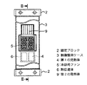
図1はこの発明の実施の形態1のエレベータの制御装置の正面図、図2は図1のII−II線に沿った断面図である。
このエレベータの制御装置は、昇降路壁面1に固定ブロック2を介して固定された制御盤用ケース3と、この制御盤用ケース3内に設けられエレベータの運転を制御するインバータのスイッチング素子である第1の発熱体4と、この第1の発熱体4が下側で固定され第1の発熱体4からの熱を吸収し、かつ放出する熱伝達体6と、この熱伝達体6の熱を放出する放熱フィン7に対向した冷却用ファン5と、制御盤用ケース3と昇降路壁面1との間の空間部Aに配置されているとともに冷却用ファン5により流れる空気の通路となるダクト8と、このダクト8の下流側に設けられダクト8内に一部が突出した抵抗体である第2の発熱体9とを備えている。
熱伝達体6は、ヒートパイプ(図示せず)と、このヒートパイプを埋設した良熱伝導性のアルミニウム製の金属ブロック10と、この金属ブロック10と一体の放熱フィン7とを備えている。
【0009】
このエレベータの制御装置では、冷却用ファン5の回転により、外部の空気が冷却用ファン5を通じて放熱フィン7に向かって流れる。そこでは、第1の発熱体4からの熱がヒートパイプを通じて放熱フィン7に伝達されており、空気の通過とともに放熱フィン7が冷却され、第1の発熱体4が間接的に冷却される。引き続き、空気は、図2の矢印Bに示すようにダクト8を通じて第1の発熱体4よりも高温の第2の発熱体9に向かって流れ、第2の発熱体9を冷却し、その後外部に排出される。
【0010】
図3は図1のエレベータの制御装置が運搬される時の様子を示しており、第2の発熱体9は制御盤用ケース3内に収納されているとともに、ダクト8は制御盤用ケース3から取り外されているので、制御盤用ケース3からは突出物は無く、円滑に運搬される。
なお、図4に示すように、第2の発熱体9がダクト8内に突出したことで生じる空間にエレベータ保守専用機器11を取り付けるようにしてもよい。
【0011】
上記構成のエレベータの制御装置によれば、第1の発熱体4を冷却した空気は、制御盤用ケース3に隣接して設けられたダクト8を通じて直接第2の発熱体9に向かって流れるようになっているので、冷却用の空気は第2の発熱体9に確実に到達し、第2の発熱体9の冷却効率が向上する。
【0012】
また、第2の発熱体9の一部はダクト8内に突出しているので、第2の発熱体9はより多くの空気にさらされので、第2の発熱体9の冷却効率はより向上する。また、第2の発熱体9がダクト8内に突出したことで生じる空間にエレベータ保守専用機器11を取り付けるようにして、空間を有効利用することもできる。また、保守専用機器11が不要のときには、その空間分の制御盤用ケースの外形寸法を小さくすることもできる。
【0013】
また、第1の発熱体4は、第1の発熱体4からの熱を吸収し、かつ放出する熱伝達体6に固定されており、熱伝達体6の熱を放出する放熱フィン7が冷却用ファン5に対向しているので、第1の発熱体4の熱は放熱フィン7を通じて効率良く冷却され、制御盤用ケース3内の温度上昇を抑制することができる。また、第1の発熱体4を冷却用ファン5に対向させる必要性が無く、第1の発熱体4および冷却用ファン5の設計自由度が向上する。
【0014】
また、制御盤用ケース3は、ダクト8は、制御盤用ケース3と昇降路壁面1との間の空間部Aに配置されており、ダクト8用にわざわざスペースを確保する必要性がない。
【0015】
なお、上記の実施の形態では、第2の発熱体9の一部が、ダクト8内に突出していたが、第2の発熱体の全体がダクト内に突出するようにしてもよい。
また、第2の発熱体が制御盤用ケース内で、かつダクトの出口に配設されていてもよい。
また、第1の発熱体が直接冷却用ファンに対向して設けられ、冷却用ファンにより直接第1の発熱体が冷却されるようにしてもよい。この場合には、勿論熱伝達対は不要である。
【0016】
実施の形態2.
図5はこの発明の実施の形態2のエレベータの制御装置の断面図である。
この実施の形態のエレベータの制御装置では、制御盤用ケース3は、ダクト20を介して第2の発熱体9を収納した付属盤用ケース21に接続されており、かつ付属盤用ケース21は機械室壁面22から離間して配置されている。また、制御盤用ケース3および付属盤用ケース21の底部には渡り線用ダクト24が設けられており、この渡り線用ダクト24内には制御盤用ケース3内の電気部品と付属盤用ケース21内の電気部品とを接続する渡り線23が延設されている。
【0017】
このエレベータの制御装置では、冷却用ファン5の回転により、外部の空気が矢印Cに示すように冷却用ファン5を通じて放熱フィン7に向かって流れる。そこでは、第1の発熱体4からの熱がヒートパイプを通じて放熱フィン7に伝達されており、空気の通過とともに放熱フィン7が冷却され、第1の発熱体4が間接的に冷却される。
引き続き、空気は、矢印Dに示すようにダクト20を通じて付属盤用ケース21内に流入し、付属盤用ケース21を貫通したダクト20により案内されて第2の発熱体9に向かって流れ、第2の発熱体9は冷却される。その後、空気は、付属盤用ケース21と機械室壁面22との間の空間部Eに排出される。
【0018】
このエレベータの制御装置によれば、第1の発熱体4の下流側に配置された第2の発熱体9はダクト9内に設けられており、冷却用の空気はダクト9に案内されて第2の発熱体9に確実に到達し、第2の発熱体9の冷却効率が向上する。
また、それぞれのケース3,21に発熱体4,9が収納されているものの、冷却用ファン5で生じた空気流は、第2の発熱体9にも到達し、第2の発熱体9も冷却用ファン5により冷却されるので、第2の発熱体9用の冷却用ファンを設ける必要性がなく、冷却用ファンを削減することができる。
【0019】
また、機械室内に配置された制御盤用ケースおよび付属盤用ケースは、通常発熱体からの熱気を外部に排出するために機械室壁面22からそれぞれ離間して配置しなければならないが、この実施の形態の場合、付属盤用ケース21と機械室壁面22との間だけを離間することで、第1の発熱体4および第2の発熱体9からの熱を外部に排出することができ、機械室内での制御盤用ケース3および付属盤用ケース21が必要とする占有スペースが少なくて済む。
【0020】
実施の形態3.
図6はこの発明の実施の形態3のエレベータの制御装置の断面図である。
この実施の形態のエレベータの制御装置では、制御盤用ケース3内の電気部品と付属盤用ケース21内の電気部品とを電気的に接続した第1の渡り線25が、制御盤用ケース3および付属盤用ケース21の底部に設けられた第1の渡り線用ダクト26内に延設されている。また、制御盤用ケース3内の電気部品と付属盤用ケース21内の電気部品とを電気的に接続した第2の渡り線27が、制御盤用ケース3および付属盤用ケース21の底部から高さ方向に離れて設けられた第2の渡り線用ダクト28を貫通している。
他の構成は、実施の形態2と同様である。
【0021】
この実施の形態では、第2の渡り線27が、制御盤用ケース3および付属盤用ケース21の底部から高さ方向に離れて設けられている。従って、実施の形態2のエレベータの制御装置と比較して、第1の渡り線用ダクト26内を貫通した第1の渡り線25の本数を削減することができ、第1の渡り線用ダクト26の高さを実施の形態2の渡り線用ダクト24と比較して低くすることができ、制御盤用ケース3および付属盤用ケース21の全高Hを低くすることができる。
【0022】
実施の形態4.
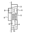
図7はこの発明の実施の形態4のエレベータの制御装置の平断面図、図8は図7のVIII−VIII線に沿った矢視断面図である。
このエレベータの制御装置は、制御盤用ケース30と、この制御盤用ケース30内に設けられエレベータの運転を制御する電気部品である発熱体31と、制御盤用ケース30を貫通したダクト32と、発熱体31に固定され発熱体31からの熱を吸収し、かつ放出するとともに放熱する放熱部である放熱フィン33がダクト32内に突出している熱伝達体34と、ダクト32内に設けられ放熱フィン33に対向した冷却用ファン35と、ダクト32に形成された通気孔36に設けられダクト32の流路面積を縮小させ、ダクト32の外部の空気をダクト32内に導く平板状の案内部材37とを備えている。
前記熱伝達体34は、ヒートパイプ(図示せず)と、このヒートパイプを埋設した良熱伝導性のアルミニウム製の金属ブロック38と、この金属ブロック38と一体で放熱フィン33とを備えている。
【0023】
このエレベータの制御装置では、冷却用ファン35の回転により、外部の空気が矢印Fに示すように冷却用ファン35を通じて放熱フィン33に向かって流れる。そこでは、発熱体31からの熱がヒートパイプを通じて放熱フィン33に伝達されており、空気の通過とともに放熱フィン33が冷却され、発熱体31が間接的に冷却される。
引き続き、空気は、矢印Gに示すように案内部材37を通過するが、通過の際、案内部材37により、空気の流路面積が縮小しており、空気の流速が増大し、動圧が大きくなるのに対して静圧が減少する。その結果、ダクト32外の電気部品39により生じた熱気は、矢印Iに示すように通気孔36を通じて流入し、冷却用ファン35からの空気と合流し、そのまま制御盤用ケース30の外部に排出される。
【0024】
このエレベータの制御装置によれば、ダクト32の通気孔36の近傍にダクト32の流路面積を縮小させ、ダクト32の外部の空気をダクト32内に導く平板状の案内部材37を設けたので、制御盤用ケース30内では、強制対流が生じ、制御盤用ケース30内で、ダクト32の外部の電気部品39の冷却効率が向上する。
【0025】
【発明の効果】
以上説明したように、この発明に係るエレベータの制御装置によれば、制御盤用ケースと、この制御盤用ケース内に設けられエレベータの運転を制御する電気部品である第1の発熱体と、この第1の発熱体を冷却する冷却用ファンと、この冷却用ファンにより流れる空気の下流側に設けられ前記第1の発熱体よりも高温の電気部品である第2の発熱体と、前記制御盤用ケースに隣接して設けられたダクトとを備え、前記空気は、前記ダクトを通じて前記第2の発熱体に流れるようになっているので、空気流の下流側の第2の発熱体が確実に冷却され、第2の発熱体の冷却効率が向上する。
【0026】
また、この発明に係るエレベータの制御装置によれば、制御盤用ケースと、この制御盤用ケース内に設けられエレベータの運転を制御する電気部品である発熱体と、前記制御盤用ケースを貫通したダクトと、前記発熱体に固定され発熱体からの熱を吸収し、かつ放出するとともに放熱する放熱部が前記ダクト内に突出している熱伝達体と、前記ダクト内に設けられ前記放熱部に対向した冷却用ファンと、前記ダクトに形成された通気孔の近傍に設けられダクトの流路面積を縮小させ、ダクトの外部の空気をダクト内に導く案内部材とを備えているので、制御盤用ケース内では、強制対流が生じ、制御盤用ケース内で、ダクトの外部の電気部品の冷却効率が向上する。
【図面の簡単な説明】
【図1】この発明の実施の形態1のエレベータの制御装置の正面図である。
【図2】図1のII−II線に沿った断面図である。
【図3】図1のエレベータの制御装置の運搬時における様子を示す断面図である。
【図4】図1のエレベータの制御装置の別の使用態様を示す断面図である。
【図5】この発明の実施の形態2のエレベータの制御装置の断面図である。
【図6】この発明の実施の形態3のエレベータの制御装置の断面図である。
【図7】この発明の実施の形態4のエレベータの制御装置の平断面図である。
【図8】図7のVIII−VIII線に沿った矢視断面図である。
【符号の説明】
1 昇降路壁面、2 固定ブロック、3,30 制御盤用ケース、4 第1の発熱体、5,35 冷却用ファン、6,34 熱伝達体、7,33 放熱フィン、8,20,32 ダクト、9 第2の発熱体、21 付属盤用ケース、22 機械室壁面、25 第1の渡り線、26 第1の渡り線用ダクト、27 第2の渡り線、28 第2の渡り線用ダクト、31 発熱体、36 通気孔、37 案内部材。[0001]
TECHNICAL FIELD OF THE INVENTION
The present invention provides a control panel case, a heating element provided in the control panel case, which is an electric component for controlling operation of an elevator, a cooling fan for cooling the heating element, and a cooling fan. The present invention relates to an elevator control device including a duct for guiding air to a heating element.
[0002]
[Prior art]
Conventionally, as a control device for an elevator, a housing that houses various electric components for elevator control, has a cooling air inlet and a cooling air outlet, and a radiating fin on which a heat-dissipating electric component among the electric components is mounted. 2. Description of the Related Art An elevator control device including a cooling fan that generates an airflow for cooling electric components requiring heat radiation is known (for example, see Patent Document 1).
[0003]
[Patent Document 1]
JP-A-4-338074 (FIG. 3)
[0004]
[Problems to be solved by the invention]
In the conventional elevator control device, the electric components on the downstream side of the airflow become shadows of the electric components on the upstream side, the airflow does not reach the electric components on the downstream side reliably, and the cooling efficiency of the electric components on the downstream side is reduced. There was a problem that it was lowered.
[0005]
An object of the present invention is to solve such a problem, and an object of the present invention is to provide an elevator control device in which electric components downstream of an airflow are reliably cooled.
[0006]
[Means for Solving the Problems]
An elevator control apparatus according to the present invention includes a control panel case, a first heating element provided in the control panel case and serving as an electric component for controlling operation of the elevator, and cooling the first heating element. A cooling fan to be provided, a second heating element provided downstream of the air flowing by the cooling fan and being an electric component having a higher temperature than the first heating element, and a cooling fan provided adjacent to the control panel case. And a second duct, wherein the air flows through the duct to the second heating element.
[0007]
Further, the elevator control device according to the present invention includes a control panel case, a heating element provided in the control panel case and serving as an electric component for controlling the operation of the elevator, and a duct penetrating the control panel case. A heat transfer member fixed to the heating element, absorbing heat from the heating element, and releasing and radiating heat, and a heat transfer element protruding into the duct, and provided in the duct and opposed to the heat radiation section. A cooling fan; and a guide member provided near the ventilation hole formed in the duct to reduce a flow passage area of the duct and guide air outside the duct into the duct.
[0008]
BEST MODE FOR CARRYING OUT THE INVENTION
Hereinafter, an elevator control device according to each embodiment of the present invention will be described. In the drawings, the same, corresponding members, and portions are denoted by the same reference numerals. Embodiment 1 FIG.
FIG. 1 is a front view of an elevator control device according to Embodiment 1 of the present invention, and FIG. 2 is a cross-sectional view taken along line II-II of FIG.
The control device for the elevator is a control panel case 3 fixed to the hoistway wall 1 via a
The
[0009]
In the elevator control device, the rotation of the
[0010]
FIG. 3 shows a state in which the elevator control device of FIG. 1 is transported. The
In addition, as shown in FIG. 4, the elevator maintenance-
[0011]
According to the elevator control device having the above configuration, the air that has cooled the
[0012]
Further, since a part of the
[0013]
The
[0014]
In the control panel case 3, the
[0015]
In the above-described embodiment, a part of the
Further, the second heating element may be provided in the case for the control panel and at the outlet of the duct.
Further, the first heating element may be provided directly opposite to the cooling fan, and the first heating element may be directly cooled by the cooling fan. In this case, of course, no heat transfer couple is required.
[0016]
FIG. 5 is a sectional view of an elevator control device according to
In the elevator control device of this embodiment, the control panel case 3 is connected to the
[0017]
In the elevator control device, the rotation of the cooling
Subsequently, the air flows into the
[0018]
According to the elevator control device, the
Although the
[0019]
In addition, the control panel case and the accessory panel case arranged in the machine room usually have to be arranged separately from the
[0020]
Embodiment 3 FIG.
FIG. 6 is a sectional view of an elevator control device according to Embodiment 3 of the present invention.
In the elevator control device of this embodiment, the
Other configurations are the same as in the second embodiment.
[0021]
In this embodiment, the
[0022]
FIG. 7 is a plan sectional view of an elevator control device according to
The elevator control device includes a
The
[0023]
In the elevator controller, the rotation of the cooling
Subsequently, the air passes through the
[0024]
According to the elevator control device, the flow path area of the
[0025]
【The invention's effect】
As described above, according to the elevator control device of the present invention, the control panel case, the first heating element that is an electric component provided in the control panel case and that controls the operation of the elevator, A cooling fan that cools the first heating element, a second heating element that is provided downstream of the air flowing by the cooling fan and is an electric component that is higher in temperature than the first heating element, and A duct provided adjacent to the panel case, wherein the air flows through the duct to the second heating element, so that the second heating element downstream of the air flow is reliably And the cooling efficiency of the second heating element is improved.
[0026]
Further, according to the elevator control device of the present invention, a control panel case, a heating element provided in the control panel case and serving as an electric component for controlling operation of the elevator, and penetrating the control panel case are provided. A heat transfer body that is fixed to the heating element, absorbs heat from the heating element, and emits and radiates heat while projecting into the duct. The control panel is provided with an opposing cooling fan and a guide member provided near the ventilation hole formed in the duct to reduce the flow passage area of the duct and guide air outside the duct into the duct. In the control case, forced convection occurs, and in the control panel case, the cooling efficiency of electric components outside the duct is improved.
[Brief description of the drawings]
FIG. 1 is a front view of an elevator control device according to Embodiment 1 of the present invention.
FIG. 2 is a sectional view taken along the line II-II in FIG.
FIG. 3 is a cross-sectional view illustrating a state of the elevator control device of FIG. 1 during transportation.
FIG. 4 is a cross-sectional view showing another mode of use of the elevator control device of FIG. 1;
FIG. 5 is a sectional view of an elevator control device according to
FIG. 6 is a sectional view of an elevator control device according to Embodiment 3 of the present invention.
FIG. 7 is a plan sectional view of an elevator control device according to
8 is a sectional view taken along the line VIII-VIII in FIG.
[Explanation of symbols]
DESCRIPTION OF SYMBOLS 1 Hoistway wall, 2 fixed blocks, 3, 30 Control panel case, 4 1st heating element, 5, 35 Cooling fan, 6, 34 Heat transfer element, 7, 33 Heat radiation fin, 8, 20, 32 Duct , 9 Second heating element, 21 Attached panel case, 22 Machine room wall surface, 25 First crossover, 26 First crossover duct, 27 Second crossover, 28 Second crossover duct , 31 heating element, 36 ventilation hole, 37 guide member.
Claims (8)
Priority Applications (1)
| Application Number | Priority Date | Filing Date | Title |
|---|---|---|---|
| JP2003066400A JP2004269244A (en) | 2003-03-12 | 2003-03-12 | Control device of elevator |
Applications Claiming Priority (1)
| Application Number | Priority Date | Filing Date | Title |
|---|---|---|---|
| JP2003066400A JP2004269244A (en) | 2003-03-12 | 2003-03-12 | Control device of elevator |
Publications (1)
| Publication Number | Publication Date |
|---|---|
| JP2004269244A true JP2004269244A (en) | 2004-09-30 |
Family
ID=33127129
Family Applications (1)
| Application Number | Title | Priority Date | Filing Date |
|---|---|---|---|
| JP2003066400A Pending JP2004269244A (en) | 2003-03-12 | 2003-03-12 | Control device of elevator |
Country Status (1)
| Country | Link |
|---|---|
| JP (1) | JP2004269244A (en) |
Cited By (7)
| Publication number | Priority date | Publication date | Assignee | Title |
|---|---|---|---|---|
| JP2007045561A (en) * | 2005-08-09 | 2007-02-22 | Mitsubishi Electric Corp | Elevator control device |
| JP2009227459A (en) * | 2008-03-25 | 2009-10-08 | Mitsubishi Electric Corp | Elevator device |
| JP2011202889A (en) * | 2010-03-25 | 2011-10-13 | Daikin Industries Ltd | Cooling structure of electric component in air conditioner |
| WO2012070145A1 (en) * | 2010-11-26 | 2012-05-31 | 三菱電機株式会社 | Cooling device for elevator |
| CN103346492A (en) * | 2013-06-24 | 2013-10-09 | 向荣集团有限公司 | Switch cabinet |
| JP2016216194A (en) * | 2015-05-20 | 2016-12-22 | 三菱電機株式会社 | Elevator control device |
| JP2022065736A (en) * | 2020-10-16 | 2022-04-28 | 三菱電機株式会社 | Board device |
-
2003
- 2003-03-12 JP JP2003066400A patent/JP2004269244A/en active Pending
Cited By (10)
| Publication number | Priority date | Publication date | Assignee | Title |
|---|---|---|---|---|
| JP2007045561A (en) * | 2005-08-09 | 2007-02-22 | Mitsubishi Electric Corp | Elevator control device |
| JP2009227459A (en) * | 2008-03-25 | 2009-10-08 | Mitsubishi Electric Corp | Elevator device |
| JP2011202889A (en) * | 2010-03-25 | 2011-10-13 | Daikin Industries Ltd | Cooling structure of electric component in air conditioner |
| WO2012070145A1 (en) * | 2010-11-26 | 2012-05-31 | 三菱電機株式会社 | Cooling device for elevator |
| CN103228564A (en) * | 2010-11-26 | 2013-07-31 | 三菱电机株式会社 | Cooling device for elevator |
| JP5617931B2 (en) * | 2010-11-26 | 2014-11-05 | 三菱電機株式会社 | Elevator cooling system |
| CN103346492A (en) * | 2013-06-24 | 2013-10-09 | 向荣集团有限公司 | Switch cabinet |
| JP2016216194A (en) * | 2015-05-20 | 2016-12-22 | 三菱電機株式会社 | Elevator control device |
| JP2022065736A (en) * | 2020-10-16 | 2022-04-28 | 三菱電機株式会社 | Board device |
| JP7391001B2 (en) | 2020-10-16 | 2023-12-04 | 三菱電機株式会社 | panel device |
Similar Documents
| Publication | Publication Date | Title |
|---|---|---|
| KR101896569B1 (en) | Heat dissipation apparatus of semiconductor module | |
| WO2012077374A1 (en) | Electrical-equipment panel | |
| JP4543333B2 (en) | control panel | |
| JP4500778B2 (en) | Induction heating cooker | |
| TWI495424B (en) | Heat dissipation device and electronic device having the same | |
| TWI318099B (en) | Active heat-dissipating type power supply system with heat-dissipating mechanism of power input device | |
| CN111386005B (en) | Control panel of machine tool | |
| JP4498367B2 (en) | Power panel | |
| CN101123863A (en) | Wind scooper | |
| KR20140053597A (en) | Cooling device for electronic machine | |
| US7023696B2 (en) | Cooling device and electric or electronic apparatus employing the same | |
| JP4236075B2 (en) | Elevator control device | |
| JP5556288B2 (en) | Heat dissipation unit and electronic device using the same | |
| JP2004269244A (en) | Control device of elevator | |
| JP2008187136A (en) | Heat dissipating structure | |
| JP2007220566A (en) | Induction heating cooker | |
| JP2004349548A (en) | Heat sink and electric controller equipped with it | |
| JP2006119234A (en) | Electrical apparatus and image forming apparatus | |
| JP2009100508A (en) | Ventilating cooler for control panel, and control panel using it | |
| KR20200001617U (en) | Heatsink module with improved air flow | |
| JP2002368473A (en) | Heat dissipating apparatus for heat generating electronic component, electronic apparatus and electronic device having heat dissipating structure | |
| WO2019150577A1 (en) | Outdoor unit and air conditioner | |
| JP2007335624A (en) | Liquid cooling equipment for electronic equipment | |
| US20050189088A1 (en) | Circulation structure of heat dissipation device | |
| WO2023272927A1 (en) | Electric control box, air conditioner outdoor unit and air conditioner |
Legal Events
| Date | Code | Title | Description |
|---|---|---|---|
| A621 | Written request for application examination |
Free format text: JAPANESE INTERMEDIATE CODE: A621 Effective date: 20060213 |
|
| A977 | Report on retrieval |
Free format text: JAPANESE INTERMEDIATE CODE: A971007 Effective date: 20081002 |
|
| A131 | Notification of reasons for refusal |
Free format text: JAPANESE INTERMEDIATE CODE: A131 Effective date: 20081014 |
|
| A02 | Decision of refusal |
Free format text: JAPANESE INTERMEDIATE CODE: A02 Effective date: 20090303 |