JP2004268762A - Crawler frame of construction machine - Google Patents
Crawler frame of construction machine Download PDFInfo
- Publication number
- JP2004268762A JP2004268762A JP2003063094A JP2003063094A JP2004268762A JP 2004268762 A JP2004268762 A JP 2004268762A JP 2003063094 A JP2003063094 A JP 2003063094A JP 2003063094 A JP2003063094 A JP 2003063094A JP 2004268762 A JP2004268762 A JP 2004268762A
- Authority
- JP
- Japan
- Prior art keywords
- frame
- leg portion
- leg
- construction machine
- center frame
- Prior art date
- Legal status (The legal status is an assumption and is not a legal conclusion. Google has not performed a legal analysis and makes no representation as to the accuracy of the status listed.)
- Granted
Links
Images


Abstract
Description
【0001】
【発明の属する技術分野】
本発明は、油圧ショベル等の建設機械のクローラフレームに関するものである。
【0002】
【従来の技術】
一般に、油圧ショベル等の建設機械は、クローラフレームを装置本体とするクローラ走行装置(下部走行体)と、このクローラ走行装置上に旋回自在に載置される上部旋回体とを備え、この上部旋回体上に作業機、キャブ、エンジン等が搭載されて構成されている。
【0003】
前記クローラフレームは、前記上部旋回体を中央部に旋回自在に支持するセンターフレームと、このセンターフレームの左右両側に連結されて前後に延設されるトラックフレームとを備え、左右のトラックフレームの前後端部にアイドラと駆動輪とをそれぞれ支持するようにされている。また、前記センターフレームは、旋回ベアリングを支持する中央フレーム部と、この中央フレーム部の左右両側に設けられその中央フレーム部とトラックフレームとを連結するレグ部(脚部)とよりなり、全て板金構造で、平面視において略H型もしくは略X型のフレーム形状に形成されている。この場合、中央部の旋回ベアリングにかかる荷重を受けるために、この旋回ベアリングを載置する上面板とその下方に配される下面板との間に、所要数の縦壁部材を溶接により接合した構造が採用されている(特許文献1,2,3参照)。
【0004】
【特許文献1】
特開平8−72615号公報
【特許文献2】
特開平11−93209号公報
【特許文献3】
特開2000−230252号公報
【0005】
【発明が解決しようとする課題】
しかしながら、前記従来のセンターフレーム構造では、左右のトラックフレーム間を板金加工鋼板よりなるレグ部で連結するようにされているために、この鋼板の形状が複雑で、かつ部品点数が多くなり、それに伴って溶接箇所が多くて溶接工数が増し、製造に多大の時間とコストとがかかってしまうという問題点がある。
【0006】
また、前記鋼板製のレグ部は上面が平面に形成されているために、作業時もしくは走行時に機内に侵入してきた泥土がそのレグ部の上面に付着・堆積し、この泥土が旋回ベアリング部に侵入してそのベアリングを損傷させたり、あるいはトラックフレームの上面に移動して上転輪の回転を妨げたり、更には上転輪の偏摩耗を引き起こすといった問題点がある。
【0007】
そこで、このような問題点に対処するために、レグ部を鋳鋼鋳物により形成するとともに、このレグ部の基端部にフランジ部を設け、このフランジ部を箱型の中央フレーム部の側面に溶接接合してなるセンターフレーム構造が考えられている。このような構造によれば、部品点数を減らすことができるとともに、溶接工数も減らすことができて加工工程、加工時間を大幅に低減させることが可能である。また、その際、レグ部の断面形状を上面が凸状となる筒型形状にすることで、泥土の付着・堆積の問題も解消することができる。
【0008】
ところが、この鋳物製のレグ部を含むセンターフレーム構造においても、中央フレーム部を箱型の板金構造にしており、この板金製の縦壁にレグ部を溶接接合する構造を採用しているために、旋回ベアリングにかかる荷重を受ける強度メンバーとしての縦壁構造の面でも、部品点数の面でも未だ改善の余地があり、更なる構造の簡素化が求められている。
【0009】
本発明は、このような事情に鑑みてなされたもので、センターフレームのレグ部を鋳物で形成するようにしたものにおいて、部品点数をより低減して構造の簡素化を図ることのできる建設機械のクローラフレームを提供することを目的とするものである。
【0010】
【課題を解決するための手段および作用・効果】
前記目的を達成するために、本発明による建設機械のクローラフレームは、
旋回ベアリングを支持する中央フレーム部とその中央フレーム部の左右両側に設けられるレグ部とよりなるセンターフレームと、このセンターフレームのレグ部先端側に設けられるトラックフレームを備える建設機械のクローラフレームにおいて、
前記レグ部を鋳物で形成するとともに、このレグ部の基端部に縦壁を一体形成することを特徴とするものである。
【0011】
本発明によれば、センターフレームにおける中央フレーム部とトラックフレームとを繋ぐレグ部が鋳物で形成されているので、鋼板による板金加工のものに比べて、部品点数を減らすことができ、また溶接箇所を少なくすることができて加工工数も大幅に減らすことができる。また、レグ部の基端部に縦壁が一体形成されているので、このレグ部の縦壁によって旋回ベアリングにかかる荷重を受けることができ、そのレグ部を接合する箇所の中央フレーム部における縦壁を省略することができる。この結果、より部品点数を減らすことができ、簡素な構造により所要の強度を確保することができる。また、レグ部を鋳物で形成することにより、このレグ部の肉厚を上部旋回体の荷重に応じて容易に変更することが可能であり、またそのレグ部の上面形状を容易に凸形状に形成できるので、泥土が落下し易い形状となってその付着・堆積を確実に防ぐことができる。
【0012】
本発明において、前記レグ部は二股状に形成されるとともに、その根元部において前後に二分割構造とされているのが好ましい。また、前記レグ部の前後二分割構造の根元部が溶接によって一体構造とされているのが好ましい。こうすることで、レグ部の鋳造がより容易に行えるとともに、その組付けが容易に行えることになって、センターフレームの製作がより容易となる。
【0013】
また、前記レグ部の縦壁は、前記旋回ベアリングを受支するサークル台の略直下に位置するように設けられるのが好ましい。こうすることで、旋回ベアリングにかかる上部旋回体の荷重をレグ部の縦壁によって直に受けることができるので、上部旋回体の荷重を支持する上で最も合理的な構造となる。
【0014】
本発明において、前記レグ部の縦壁には油圧配管を挿通させる孔が形成され、この孔の縁部が厚肉に形成されるのが好ましい。このようにすれば、上部旋回体側に設けた油圧ポンプから、トラックフレーム側に設けた油圧モータへの油圧配管の取り回しが容易に行えるだけでなく、レグ部の重量軽減にも寄与することができる。また、この孔の縁部を厚肉に形成することによってその部分を強化することができ、この厚肉によって孔の縁部が角張るのを防ぐことができるので、板金製の縦壁のようにその配管孔にグロメットを装着する必要がなくなる。
【0015】
また、前記中央フレーム部の上面板および下面板と前記レグ部との溶接部はJ形開先にされて、これら上面板および下面板の表面とレグ部の表面とが面一になるようにされているのが好ましい。こうすることで、レグ部の高さを高くすることができて剛性を高めることができるとともに、J形開先で調整代を取ることができるので、仮付けし易く、位置合わせも容易であり、しかも応力集中が起こりにくいという効果がある。
【0016】
【発明の実施の形態】
次に、本発明による建設機械のクローラフレームの具体的な実施の形態について、図面を参照しつつ説明する。
【0017】
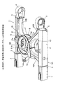
図1には油圧ショベルに適用した本発明の一実施形態に係るクローラフレームの全体斜視図が示され、図2には本実施形態のクローラフレームの平面図が、図3にはその正面図が、図4にはその側面図がそれぞれ示されている。また、図5にはレグ部を下方側から見た斜視図が示されている。
【0018】
本実施形態のクローラフレーム1は、センターフレーム2と、このセンターフレーム2の左右両側に配されて車体前後方向に延設されるトラックフレーム3A,3Bとにより構成されている。各トラックフレーム3A,3Bは、中央部に配される門型断面の支持枠4と、この支持枠4の前後端に板材5,6を介して支持されるアイドラ支持体7および駆動輪支持体8とを備え、これらアイドラ支持体7および駆動輪支持体8にそれぞれアイドラおよび駆動輪(いずれも図示せず)を支持するように構成されている。
【0019】
前記センターフレーム2は、中央フレーム部9と、この中央フレーム部9の左右両側に設けられるレグ部10,11とよりなり、これらレグ部10,11の先端部が前記トラックフレーム3A,3Bの各支持枠4,4の側面に接合されるように構成されている。
【0020】
前記中央フレーム部9は、鋼板等の材料により形成され、図6に示されるように、中央部にスイベルジョイントおよび配管等を挿通させる孔12aを有する略半楕円形状の上面板12と、半楕円形状の板材の前端部を垂直に折り曲げて前壁部13aが形成されてなる下面板13と、これら上面板12と下面板13の後部を覆うように所要部を折り曲げて形成される後面板14とにより構成されている。この中央フレーム部9は、両側面が開放した箱形形状に組み立てられた後、その上面板12の上面に旋回ベアリングを受支するサークル台15が載置・固定される。
【0021】
一方、前記中央フレーム部9の左右に配される各レグ部10,11は二股状(平面視略V字形状)に形成されて全体として平面視で略X型になるようにされ、これによって中央フレーム部9に作用する上部旋回体の荷重が4本のレグ部に分散されてその荷重が効果的に支持されるようになっている。左側のレグ部10と右側のレグ部11とは線対称の関係にあって同様の構成であるので、以下、左側のレグ部10を代表としてその構成等について説明することとする。
【0022】
この左側のレグ部10は、二股状となったその根元部において前後に前部レグ部10Aと後部レグ部10Bとに二分割構造とされている。各レグ部10A,10Bは鋳鋼鋳物により上面が凸の断面略五角筒状に一体形成され、これら前部レグ部10Aおよび後部レグ部10Bが基端側の接合部10aにて相互に嵌め合わされて溶接接合により一体化される。
【0023】
図5に示されるように、前記レグ部10の基端部には縦壁10bが一体形成され、この縦壁10bには各レグ部10A,10Bの内部空間と連通する円形の孔(鋳物孔)10c,10dが設けられている。また、このレグ部10の基端面、言い換えれば縦壁10bの表面は前記サークル台15の内周面と略同一曲率の円弧面に形成され、このレグ部10を中央フレーム部9に接合した際にその縦壁10bがサークル台15の円弧部の直下に位置するようにされている。
【0024】
また、前記レグ部10の基端部には、その基端部側が段下がり状になるように段部10eが形成されている。この段部10eは、平面視で前記中央フレーム部9の上面板12および下面板13の側縁形状に一致するような曲線形状とされ、これら上面板12および下面板13の側縁をその段部10eにあてがって、それら上面板12、下面板13とレグ部10との相互間を溶接接合するようにされている。なお、前記段部10eより基端側におけるレグ部10の前面部10fは、中央フレーム部9における下面板13の前壁部13aの側部内面に溶接接合され、またレグ部10の後面部10gは、中央フレーム部9における後面板14の側部内面に溶接接合される。
【0025】
一方、前部レグ部10Aの先端部には、トラックフレーム3Aの支持枠4の内壁面に接当されてその内壁面に溶接接合される接合フランジ部10hが設けられている。また、後部レグ部10Bの先端部には、トラックフレーム3Aの支持枠4の内壁面に接当されてその内壁面に溶接接合される接合フランジ部10iと、この接合フランジ部10iに連設されて支持枠4の後端に固着される板材6に溶接接合されるコ字状の接合部10jが設けられている。
【0026】
次に、上面板12、下面板13とレグ部10との接合構造および縦板10bの構造を図7を参照しつつより詳細に説明する。
【0027】
図示のように、前記上面板12および下面板13とレグ部10との接合部には段部10eが形成されていて、この段部10e上面と上面板12の端面との間および段部10e下面と下面板13の端面との間にはそれぞれJ形開先16が形成されている。こうして、このJ形開先16部分を溶接することで、上面板12および下面板13の表面とレグ部10の表面とが面一になるようにされている。
【0028】
このようにJ形開先16を設けることで、従来の隅肉溶接のものに比べてレグ部10の高さを高くすることができてその剛性を高めることができる。また、このJ形開先16で調整代を取ることができるので、溶接接合時の仮付けが容易となり、また位置合わせ(レグ部10と中央フレーム部9との寸法公差の吸収)も容易となる。また、この溶接接合部に応力集中が起こりにくいという効果もある。
【0029】
また、前記レグ部10の縦壁10bに設けられる孔(鋳物孔)10c,10dは、その周縁部が厚肉(額縁付き)に形成されて強化されるとともに、その厚肉部がアール形状に形成されている。そして、この孔のうち一方の孔10c(もしくは10d)には、上部旋回体側の油圧ポンプからトラックフレーム3A側の油圧モータへ至る油圧ホース等の油圧配管17が挿通される。このような構成を採用することで、油圧配管の取り回しが容易に行えるとともに、レグ部10の重量軽減を図ることができる。また、孔10c,10dの縁部の厚肉部がアール形状にされているので、油圧配管17がその部分に衝接しても傷をつけたりすることがなく、従来の板金製の縦壁を採用する場合のようにその孔の周縁部にグロメットを装着する必要がない。また、このような孔10c,10dは板金製の縦壁のようにレーザ加工等で設ける必要がなく、型抜きで形成することができるので、製作も容易である。
【0030】
また、本実施形態によれば、レグ部10,11を接合する部分における中央フレーム部9の縦壁を省略することができるので、部品点数を少なくすることができる。また、このレグ部10,11に設けられる縦壁10bがサークル台15の円弧部の直下に位置するように設けられているので、この縦壁10bによって旋回ベアリングにかかる上部旋回体の荷重を直に支持することができ、強度上も有利であるという効果がある。
【0031】
本実施形態のレグ部10,11は上面が凸の断面略五角形に形成されており、しかも鋳鋼鋳物により形成されているので、作業時等において泥土がそのレグ部10,11の上面に侵入してきたとしても、この泥土はその上面に付着・堆積せずに容易に落下する。したがって、旋回ベアリング部に侵入してそのベアリングを損傷させたり、あるいはトラックフレームの上面に移動して上転輪の回転を妨げたりすることがなく、泥はけ性が極めて良好である。
【0032】
なお、本実施形態においては、レグの断面形状を略略五角形状にしたものを説明したが、この断面形状は、略三角形状であっても、上面が円弧状の略四角形状であっても、あるいは六角形状であっても良い。
【図面の簡単な説明】
【図1】図1は、本発明の一実施形態に係るクローラフレームの全体斜視図である。
【図2】図2は、本実施形態のクローラフレームの平面図である。
【図3】図3は、本実施形態のクローラフレームの正面図である。
【図4】図4は、本実施形態のクローラフレームの側面図である。
【図5】図5は、レグ部を下方側から見た斜視図である。
【図6】図6は、中央フレーム部の分解斜視図である。
【図7】図7は、レグ部の縦壁近傍の断面形状を示す図である。
【符号の説明】
1 クローラフレーム
2 センターフレーム
3A,3B トラックフレーム
9 中央フレーム部
10,11 レグ部
10a 接合部
10b 縦壁
10c,10d 孔
10e 段部
12 上面板
13 下面板
14 後面板
15 サークル台
16 J形開先
17 油圧配管[0001]
BACKGROUND OF THE INVENTION
The present invention relates to a crawler frame of a construction machine such as a hydraulic excavator.
[0002]
[Prior art]
In general, a construction machine such as a hydraulic excavator includes a crawler traveling device (lower traveling body) having a crawler frame as an apparatus main body, and an upper revolving body that is rotatably mounted on the crawler traveling device. A work machine, cab, engine, etc. are mounted on the body.
[0003]
The crawler frame includes a center frame that pivotally supports the upper swing body at a central portion, and a track frame that is connected to both the left and right sides of the center frame and extends forward and backward. The idler and the driving wheel are respectively supported at the ends. The center frame includes a central frame portion that supports the slewing bearing and leg portions (leg portions) that are provided on both the left and right sides of the central frame portion and connect the central frame portion and the track frame. The structure is formed in a substantially H-shaped or substantially X-shaped frame shape in plan view. In this case, in order to receive the load applied to the slewing bearing in the center, a required number of vertical wall members are joined by welding between the upper surface plate on which the slewing bearing is placed and the lower surface plate disposed below the upper surface plate. A structure is employed (see
[0004]
[Patent Document 1]
JP-A-8-72615 [Patent Document 2]
JP 11-93209 A [Patent Document 3]
Japanese Patent Laid-Open No. 2000-230252
[Problems to be solved by the invention]
However, in the conventional center frame structure, the left and right track frames are connected to each other by a leg portion made of a sheet metal-worked steel plate, so that the shape of the steel plate is complicated and the number of parts is increased. Along with this, there is a problem that the number of welding points is increased, the number of welding processes is increased, and manufacturing takes much time and cost.
[0006]
Further, since the steel plate leg portion has a flat upper surface, mud that has entered the machine during work or traveling adheres to and accumulates on the upper surface of the leg portion. There is a problem that the bearing is damaged by intrusion, or moves to the upper surface of the track frame to prevent rotation of the upper roller, and further causes uneven wear of the upper roller.
[0007]
Therefore, in order to cope with such problems, the leg portion is formed by cast steel casting, and a flange portion is provided at the base end portion of the leg portion, and this flange portion is welded to the side surface of the box-shaped central frame portion. A center frame structure formed by joining is considered. According to such a structure, the number of parts can be reduced and the number of welding processes can be reduced, so that the machining process and the machining time can be greatly reduced. At that time, the cross-sectional shape of the leg portion is made into a cylindrical shape having a convex upper surface, so that the problem of mud adhesion and accumulation can be solved.
[0008]
However, even in the center frame structure including the cast leg portion, the center frame portion has a box-shaped sheet metal structure, and a structure in which the leg portion is welded to the sheet metal vertical wall is employed. There is still room for improvement in terms of the vertical wall structure as a strength member that receives the load applied to the slewing bearing and the number of parts, and further simplification of the structure is required.
[0009]
The present invention has been made in view of such circumstances. In the construction in which the leg portion of the center frame is formed of a casting, the construction machine can further reduce the number of parts and simplify the structure. It is an object to provide a crawler frame.
[0010]
[Means for solving the problems and actions / effects]
In order to achieve the above object, a crawler frame of a construction machine according to the present invention comprises:
In a crawler frame of a construction machine including a center frame that includes a center frame portion that supports a slewing bearing and leg portions that are provided on both right and left sides of the center frame portion, and a track frame that is provided on the front end side of the leg portion of the center frame.
The leg portion is formed by casting, and a vertical wall is integrally formed at the base end portion of the leg portion.
[0011]
According to the present invention, since the leg portion that connects the center frame portion and the track frame in the center frame is formed of a casting, the number of parts can be reduced as compared with that of sheet metal processing by a steel plate, and the welding location And the number of processing steps can be greatly reduced. Further, since the vertical wall is integrally formed at the base end portion of the leg portion, the vertical wall of the leg portion can receive a load applied to the swivel bearing, and the vertical frame in the central frame portion at the location where the leg portion is joined. Walls can be omitted. As a result, the number of parts can be further reduced, and the required strength can be ensured with a simple structure. In addition, by forming the leg portion from a casting, it is possible to easily change the thickness of the leg portion according to the load of the upper revolving body, and the upper surface shape of the leg portion can be easily made convex. Since it can form, it becomes the shape where mud falls easily, and the adhesion and accumulation can be prevented reliably.
[0012]
In the present invention, it is preferable that the leg portion is formed in a bifurcated shape and has a two-divided structure in the front and rear at the base portion. Moreover, it is preferable that the base part of the front-and-rear two-part structure of the leg part is an integrated structure by welding. By doing so, the leg portion can be casted more easily and the assembly thereof can be performed easily, and the center frame can be manufactured more easily.
[0013]
Moreover, it is preferable that the vertical wall of the said leg part is provided so that it may be located in the just under the circle stand which supports the said turning bearing. By doing so, the load of the upper swing body applied to the swing bearing can be directly received by the vertical wall of the leg portion, so that the most rational structure is provided for supporting the load of the upper swing body.
[0014]
In the present invention, it is preferable that a hole through which hydraulic piping is inserted is formed in the vertical wall of the leg portion, and an edge portion of the hole is formed thick. In this way, not only can the hydraulic piping be easily routed from the hydraulic pump provided on the upper swing body side to the hydraulic motor provided on the track frame side, but it can also contribute to weight reduction of the leg portion. . Moreover, by forming the edge of the hole thickly, the part can be strengthened, and it is possible to prevent the edge of the hole from being squared by the thick wall. Therefore, it is not necessary to attach a grommet to the piping hole.
[0015]
The welded portion between the upper and lower plates of the central frame portion and the leg portion is formed into a J-shaped groove so that the surface of the upper and lower plate and the surface of the leg portion are flush with each other. It is preferable. By doing so, the height of the leg portion can be increased and the rigidity can be increased, and the adjustment allowance can be taken with the J-shaped groove, so that it is easy to temporarily attach and align. In addition, there is an effect that stress concentration hardly occurs.
[0016]
DETAILED DESCRIPTION OF THE INVENTION
Next, specific embodiments of the crawler frame of the construction machine according to the present invention will be described with reference to the drawings.
[0017]
FIG. 1 is an overall perspective view of a crawler frame according to an embodiment of the present invention applied to a hydraulic excavator, FIG. 2 is a plan view of the crawler frame of this embodiment, and FIG. 3 is a front view thereof. FIG. 4 is a side view thereof. FIG. 5 shows a perspective view of the leg portion as viewed from below.
[0018]
The crawler frame 1 according to this embodiment includes a
[0019]
The
[0020]
The
[0021]
On the other hand, each
[0022]
The
[0023]
As shown in FIG. 5, a
[0024]
Further, a
[0025]
On the other hand, a
[0026]
Next, the joining structure of the
[0027]
As shown in the figure, a
[0028]
By providing the J-shaped
[0029]
Further, the holes (casting holes) 10c and 10d provided in the
[0030]
Moreover, according to this embodiment, since the vertical wall of the
[0031]
The
[0032]
In the present embodiment, the leg has been described as having a substantially pentagonal cross-sectional shape, but the cross-sectional shape may be a substantially triangular shape or a substantially quadrangular shape with an arcuate upper surface. Alternatively, it may be hexagonal.
[Brief description of the drawings]
FIG. 1 is an overall perspective view of a crawler frame according to an embodiment of the present invention.
FIG. 2 is a plan view of the crawler frame of the present embodiment.
FIG. 3 is a front view of the crawler frame of the present embodiment.
FIG. 4 is a side view of the crawler frame of the present embodiment.
FIG. 5 is a perspective view of a leg portion as viewed from below.
FIG. 6 is an exploded perspective view of a central frame portion.
FIG. 7 is a diagram showing a cross-sectional shape in the vicinity of a vertical wall of a leg portion.
[Explanation of symbols]
DESCRIPTION OF SYMBOLS 1
Claims (6)
前記レグ部を鋳物で形成するとともに、このレグ部の基端部に縦壁を一体形成することを特徴とする建設機械のクローラフレーム。In a crawler frame of a construction machine including a center frame that includes a center frame portion that supports a slewing bearing and leg portions that are provided on both right and left sides of the center frame portion, and a track frame that is provided on the front end side of the leg portion of the center frame.
A crawler frame for a construction machine, wherein the leg portion is formed of a casting, and a vertical wall is integrally formed at a base end portion of the leg portion.
Priority Applications (5)
| Application Number | Priority Date | Filing Date | Title |
|---|---|---|---|
| JP2003063094A JP4220807B2 (en) | 2003-03-10 | 2003-03-10 | Construction machinery crawler frame |
| CN2004100068316A CN1530496B (en) | 2003-03-10 | 2004-02-24 | Track frame of building machinery |
| US10/789,160 US7293375B2 (en) | 2003-03-10 | 2004-02-27 | Crawler frame for construction machine |
| EP04004733A EP1457605B1 (en) | 2003-03-10 | 2004-03-01 | Crawler frame for construction machine |
| KR1020040015851A KR100997724B1 (en) | 2003-03-10 | 2004-03-09 | Crawler frame of construction machinery |
Applications Claiming Priority (1)
| Application Number | Priority Date | Filing Date | Title |
|---|---|---|---|
| JP2003063094A JP4220807B2 (en) | 2003-03-10 | 2003-03-10 | Construction machinery crawler frame |
Publications (2)
| Publication Number | Publication Date |
|---|---|
| JP2004268762A true JP2004268762A (en) | 2004-09-30 |
| JP4220807B2 JP4220807B2 (en) | 2009-02-04 |
Family
ID=33124767
Family Applications (1)
| Application Number | Title | Priority Date | Filing Date |
|---|---|---|---|
| JP2003063094A Expired - Fee Related JP4220807B2 (en) | 2003-03-10 | 2003-03-10 | Construction machinery crawler frame |
Country Status (1)
| Country | Link |
|---|---|
| JP (1) | JP4220807B2 (en) |
Cited By (4)
| Publication number | Priority date | Publication date | Assignee | Title |
|---|---|---|---|---|
| US7293374B2 (en) * | 2002-12-06 | 2007-11-13 | Komatsu Ltd. | Crawler frame for construction machine |
| JP2009035952A (en) * | 2007-08-02 | 2009-02-19 | Hitachi Constr Mach Co Ltd | Truck frame of construction machine |
| EP2065293A1 (en) * | 2006-09-28 | 2009-06-03 | Kubota Corporation | Track frame for work machine |
| CN113619699A (en) * | 2021-08-19 | 2021-11-09 | 徐工集团工程机械股份有限公司建设机械分公司 | Frame structure with umbrella-shaped bearing device |
-
2003
- 2003-03-10 JP JP2003063094A patent/JP4220807B2/en not_active Expired - Fee Related
Cited By (7)
| Publication number | Priority date | Publication date | Assignee | Title |
|---|---|---|---|---|
| US7293374B2 (en) * | 2002-12-06 | 2007-11-13 | Komatsu Ltd. | Crawler frame for construction machine |
| EP2065293A1 (en) * | 2006-09-28 | 2009-06-03 | Kubota Corporation | Track frame for work machine |
| EP2065293A4 (en) * | 2006-09-28 | 2009-11-25 | Kubota Kk | Track frame for work machine |
| US7997619B2 (en) | 2006-09-28 | 2011-08-16 | Kubota Corporation | Track frame for work machine |
| JP2009035952A (en) * | 2007-08-02 | 2009-02-19 | Hitachi Constr Mach Co Ltd | Truck frame of construction machine |
| CN113619699A (en) * | 2021-08-19 | 2021-11-09 | 徐工集团工程机械股份有限公司建设机械分公司 | Frame structure with umbrella-shaped bearing device |
| CN113619699B (en) * | 2021-08-19 | 2022-05-24 | 徐工集团工程机械股份有限公司建设机械分公司 | Frame structure with umbrella-shaped bearing device |
Also Published As
| Publication number | Publication date |
|---|---|
| JP4220807B2 (en) | 2009-02-04 |
Similar Documents
| Publication | Publication Date | Title |
|---|---|---|
| JP5041747B2 (en) | Center frame in crawler traveling device and method of manufacturing center frame | |
| JP2000273908A (en) | Frame and under carriage built-up body | |
| KR100997724B1 (en) | Crawler frame of construction machinery | |
| US7997619B2 (en) | Track frame for work machine | |
| US7204518B2 (en) | Construction machine | |
| JP6968716B2 (en) | Floating wheel and manufacturing method of floating wheel | |
| JP4220807B2 (en) | Construction machinery crawler frame | |
| US7730647B2 (en) | Construction machine | |
| JP2004189003A (en) | Crawler frame of construction machine | |
| JP3652924B2 (en) | TRACK FRAME FOR TRAVELING DEVICE AND METHOD FOR ASSEMBLING THE SAME | |
| JP4823004B2 (en) | Track frame | |
| JP4823005B2 (en) | Track frame | |
| KR20060029281A (en) | Revoling-frame structure of construction machinery | |
| JP4693734B2 (en) | Crawler type traveling device | |
| JPH0638922Y2 (en) | Front frame of wheeled loader | |
| JP3462424B2 (en) | Truck frame for construction machinery | |
| JP4079252B2 (en) | Track frame of crawler type traveling vehicle | |
| JP4633028B2 (en) | Carrier roller support structure of crawler type traveling device | |
| JP4144740B2 (en) | Crawler frame for construction machinery | |
| JP4251444B2 (en) | Construction machinery crawler frame | |
| JP2004345380A (en) | Crawler frame of construction machinery | |
| JP2005344302A (en) | Dozer unit | |
| JPH074260U (en) | Mobile crane frame structure | |
| JP2004161216A (en) | Truck frame of working machine | |
| JP2006274595A (en) | Revolving working machine |
Legal Events
| Date | Code | Title | Description |
|---|---|---|---|
| A621 | Written request for application examination |
Free format text: JAPANESE INTERMEDIATE CODE: A621 Effective date: 20051117 |
|
| A977 | Report on retrieval |
Free format text: JAPANESE INTERMEDIATE CODE: A971007 Effective date: 20080215 |
|
| A131 | Notification of reasons for refusal |
Free format text: JAPANESE INTERMEDIATE CODE: A131 Effective date: 20080219 |
|
| A521 | Request for written amendment filed |
Free format text: JAPANESE INTERMEDIATE CODE: A523 Effective date: 20080415 |
|
| A131 | Notification of reasons for refusal |
Free format text: JAPANESE INTERMEDIATE CODE: A131 Effective date: 20080812 |
|
| A521 | Request for written amendment filed |
Free format text: JAPANESE INTERMEDIATE CODE: A523 Effective date: 20081008 |
|
| TRDD | Decision of grant or rejection written | ||
| A01 | Written decision to grant a patent or to grant a registration (utility model) |
Free format text: JAPANESE INTERMEDIATE CODE: A01 Effective date: 20081111 |
|
| A01 | Written decision to grant a patent or to grant a registration (utility model) |
Free format text: JAPANESE INTERMEDIATE CODE: A01 |
|
| A61 | First payment of annual fees (during grant procedure) |
Free format text: JAPANESE INTERMEDIATE CODE: A61 Effective date: 20081114 |
|
| FPAY | Renewal fee payment (event date is renewal date of database) |
Free format text: PAYMENT UNTIL: 20111121 Year of fee payment: 3 |
|
| R150 | Certificate of patent or registration of utility model |
Ref document number: 4220807 Country of ref document: JP Free format text: JAPANESE INTERMEDIATE CODE: R150 Free format text: JAPANESE INTERMEDIATE CODE: R150 |
|
| FPAY | Renewal fee payment (event date is renewal date of database) |
Free format text: PAYMENT UNTIL: 20121121 Year of fee payment: 4 |
|
| FPAY | Renewal fee payment (event date is renewal date of database) |
Free format text: PAYMENT UNTIL: 20131121 Year of fee payment: 5 |
|
| S111 | Request for change of ownership or part of ownership |
Free format text: JAPANESE INTERMEDIATE CODE: R313117 |
|
| R350 | Written notification of registration of transfer |
Free format text: JAPANESE INTERMEDIATE CODE: R350 |
|
| S111 | Request for change of ownership or part of ownership |
Free format text: JAPANESE INTERMEDIATE CODE: R313113 |
|
| S531 | Written request for registration of change of domicile |
Free format text: JAPANESE INTERMEDIATE CODE: R313531 |
|
| R350 | Written notification of registration of transfer |
Free format text: JAPANESE INTERMEDIATE CODE: R350 |
|
| LAPS | Cancellation because of no payment of annual fees |