JP2004268352A - Wiping member, liquid injection device, and inkjet type recording apparatus - Google Patents
Wiping member, liquid injection device, and inkjet type recording apparatus Download PDFInfo
- Publication number
- JP2004268352A JP2004268352A JP2003060687A JP2003060687A JP2004268352A JP 2004268352 A JP2004268352 A JP 2004268352A JP 2003060687 A JP2003060687 A JP 2003060687A JP 2003060687 A JP2003060687 A JP 2003060687A JP 2004268352 A JP2004268352 A JP 2004268352A
- Authority
- JP
- Japan
- Prior art keywords
- wiping member
- forming surface
- nozzle forming
- liquid ejecting
- contact
- Prior art date
- Legal status (The legal status is an assumption and is not a legal conclusion. Google has not performed a legal analysis and makes no representation as to the accuracy of the status listed.)
- Granted
Links
Images


Abstract
Description
【0001】
【発明の属する技術分野】
本発明はワイピング部材、液体噴射装置及びインクジェット式記録装置に関する。
より詳しくは、本発明はインク等の液体をそのヘッドから噴射(吐出)して被噴射媒体(被記録媒体)に液体を付着させる(記録を実行する)インクジェット式記録装置などの液体噴射装置に備えられ、ヘッドのノズル形成面を払拭するワイピング部材、このワイピング部材を備えた液体噴射装置、及びこの液体噴射装置の一例であるインクジェット式記録装置に関するものである。
【0002】
なお液体噴射装置とは、インクジェット式の記録ヘッドが用いられ、該記録ヘッドからインクを吐出して被記録媒体に記録を行うプリンタ、複写機およびファクシミリ等の記録装置に限らず、インクに換えてその用途に対応する液体を前記記録ヘッドに相当する液体噴射ヘッドから被記録媒体に相当する被噴射媒体に噴射して、前記液体を前記被噴射媒体に付着させる装置を含むものである。
【0003】
液体噴射ヘッドとして前記記録ヘッドの他に、液晶ディスプレー等のカラーフィルター製造に用いられる色材噴射ヘッド、有機ELディスプレーや面発光ディスプレー(FED)等の電極形成に用いられる電極材(導電ペースト)噴射ヘッド、バイオチップ製造に用いられる生体有機物噴射ヘッド、精密ピペットとしての試料噴射ヘッド等が挙げられる。
【0004】
【従来の技術】
ノズル開口から液体を噴射する液体噴射装置の1つにインクジェット式記録装置がある。このインクジェット式記録装置は、主走査方向(被記録媒体の幅方向)に往復移動するキャリッジに搭載され、被記録媒体に向けてインクを噴射(吐出)する記録ヘッドと、被記録媒体を副走査方向に所定量ずつ精密送りする被記録媒体搬送手段を備え、被記録媒体を副走査方向に送りつつ記録ヘッドを主走査方向に移動させることにより記録(印刷)を実行している。
【0005】
このような構成のインクジェット式記録装置に係る記録ヘッドは、圧力発生室とこれにつながるノズル開口を有しており、圧力発生室で所定圧に加圧されたインクがノズル開口から被記録媒体に向けて噴射するようになっている。そのため、記録ヘッドのノズル開口でのインク噴射特性が記録精度に大きく影響を与えるので、このインク噴射特性は常に一定に維持されていることが必要である。
【0006】
このインク噴射特性は、ノズル開口でのインク溶媒の蒸発によるインク粘性の上昇や固化、これによる目詰まり、さらに塵埃の付着やインク流路内への気泡の浸入等により変動してしまい、記録精度に問題を生じさせることがある。
【0007】
そのため、インクジェット式記録装置は、インクの噴射特性を一定に維持するための特性維持手段として、キャッピング手段、負圧発生手段及びワイピング手段を備えている(例えば、特許文献1参照)。
【0008】
キャッピング手段は、インクジェット式記録装置の非使用時にキャッピング部材でノズル形成面を封止することにより外部から隔離し、ノズル開口でのインクの乾燥や塵埃の付着を回避している。
【0009】
また、ノズルの目詰まりやインク流路内への気泡の浸入等が生じた場合に、これらを除去する負圧発生手段を備えている。この負圧発生手段は、前記キャッピング部材でノズル形成面を封止した状態でノズルに負圧を作用させるように構成されており、インクをノズルから強制的に吸引排出させて目詰まりや気泡浸入を解消する。この負圧発生手段は、通常、インクジェット式記録装置を長期間不使用であった後に使用を再開する場合やユーザーが記録精度の低下を認識した場合等に所定操作により実行できるようになっている。
【0010】
このように、目詰まりや気泡浸入を解消させるためのインクの強制吸引排出を行うと、排出されたインクが飛び散ってノズル形成面に付着することがある。この付着により、インクのメニスカスが乱れたり、さらに塵埃等の異物が吸着されることがある。このような場合に、ノズル形成面に摺動してこれを払拭するワイピング手段が備えられている。このワイピング手段は、エラストマー等の弾性素材から構成されたワイピング部材を有し、該ワイピング部材の基端部がホルダによって固定されている。そして、ワイピング部材の先端部(自由端部)をノズル形成面に当接させつつ相対移動させることで、ノズル形成面に付着したインク等の異物を取り除いて清掃するように構成されている。このワイピング手段の駆動(いわゆる、ワイピング動作)により、ノズル形成面に付着したインク等の異物が取り除かれるだけでなく、メニスカスが一様に整えられ、安定した記録を実行することができるようになっている。
【0011】
このワイピング部材による拭き取り漏れや拭き取り能力の低下などの問題に対しては、複数の拭き取り部(凸部)を備え、ワイピング動作時に全ての拭き取り部がノズル形成面に当接するように構成することによって解消できるとする報告がなされている(例えば、特許文献2参照)。
【0012】
ところで、最近のインクジェット式記録装置においては、例えば、専用紙(写真用紙等)、普通紙、厚紙、ハガキ、ボード紙、CD(CD−R等)などの様々な被記録媒体に対応させるべく、記録ヘッドのノズル形成面と被記録媒体載置面であるプラテンとのギャップ(いわゆる、プラテンギャップ)を調整するギャップ調整手段を備えた構成のものがある(例えば、特許文献3参照)。
【0013】
【特許文献1】
特開平11−334090号公報
【特許文献2】
特開平10−86393号公報
【特許文献3】
特開2002−356036号公報
【0014】
【発明が解決しようとする課題】
このようなギャップ調整手段を備えたインクジェット式記録装置では、ギャップの調整によってワイピング部材と記録ヘッドのノズル形成面との距離(間隔)が変化してしまい、これに伴って、ワイピング部材がノズル形成面を押圧する力が変化してしまっていた。そのため、プラテンギャップが大である場合にはワイピング部材による押圧力が減少してしまい、ノズル形成面を充分に払拭できずに拭き残りを生じさせ、異物を残存させてしまうことがあった。一方、プラテンギャップが小である場合にはワイピング部材による押圧力が必要以上に大きくなってしまい、ノズル形成面に不具合(例えば、ノズル形成面のメッキ層の剥離、撥水処理効果の低減など)を生じさせていた。
【0015】
本発明はこのような問題に鑑みなされたものであって、その課題は、被噴射媒体載置面と液体噴射ヘッドのノズル形成面とのギャップに対応してノズル形成面を払拭可能なワイピング部材、該ワイピング部材を備えた液体噴射装置、及び該液体噴射装置の一例であるインクジェット式記録装置を提供することにある。
【0016】
【課題を解決するための手段】
上記課題を解決するため、本発明の第1の態様に係るワイピング部材の発明は、被噴射媒体に向けてノズル開口から液体を噴射する液体噴射ヘッドと、この液体噴射ヘッドに対置された被噴射媒体載置面と、前記被噴射媒体載置面と前記液体噴射ヘッドのノズル形成面とのギャップを段階的に調整するギャップ調整手段と、前記液体噴射ヘッドに対して相対移動することにより、当該液体噴射ヘッドのノズル形成面に摺動するワイピング部材と、を備えた液体噴射装置に用いられるワイピング部材であって、前記ワイピング部材は、前記被噴射媒体載置面と前記ノズル形成面との段階的なギャップに対応して設けられ、当該ノズル形成面に当接する複数の当接部を有していることを特徴とする。
【0017】
この特徴によれば、ワイピング部材は被噴射媒体載置面とノズル形成面との段階的なギャップに対応して設けられ、ノズル形成面に当接する複数の当接部を有しているので、ギャップ調整手段によって被噴射媒体載置面とノズル形成面とのギャップ(間隔)が変化した場合においても、そのギャップに対応するワイピング部材の当接部がノズル形成面に確実に当接して摺動することにより、当該ノズル形成面を確実に払拭することができる。従って、ギャップがどのような段階であっても対応する当接部によってノズル形成面を的確に払拭することができ、拭き残し等の不具合を生じることがない。
【0018】
また、本発明の第2の態様に係るワイピング部材の発明は、前記第1の態様において、前記複数の当接部は、当該ワイピング部材の自由端部側のものほど前記ノズル形成面との接触面積が小なるように構成されていることを特徴とする。
【0019】
ワイピング部材は弾性のある素材から形成されており、ノズル形成面に摺接した状態で適度に変形し、その復元力を利用してノズル形成面に摺接しているため、ノズル形成面に対する押圧力が自由端部(先端部)側ほど小さくなり、基端部(固定端部)側ほど大きくなる。そのため、ワイピング部材の自由端部側でノズル形成面に当接すると押圧力が小さ過ぎ、払拭が充分に行われず、拭き残しが発生することがある。一方、基端部側で当接すると押圧力が大き過ぎ、不具合(例えば、ノズル形成面のメッキ層の剥離、撥水処理効果の低減など)を生じさせる虞がある。
【0020】
しかし本発明では、複数の当接部はワイピング部材の自由端部側のものほどノズル形成面との接触面積が小なるように構成されているので、ギャップが大きい場合に自由端部側の当接部でノズル形成面に当接しても、これを充分に払拭することが可能である。一方、ギャップが小さい場合に基端部側の当接部でノズル形成面に当接しても、ノズル形成面との接触面積が大きくなることにより押圧力が大きすぎることによる上記不具合を回避することができる。
【0021】
すなわち、ワイピング部材の当接部によるノズル形成面に対する押圧力は、自由端部側のものほど小さく、基端部側のものほど大きくなる。そして、ノズル形成面に対する接触面積を、押圧力と同様に自由端部側のものほど小さく、基端部側のものほど大きく構成することにより、いずれの当接部においても単位面積当たりの押圧力(すなわち、圧力)がほぼ一定となるため、ギャップに関係なくノズル形成面を均一に払拭することが可能である。従って、ギャップに伴うワイピング部材の摺接程度の違いが回避され、常に一定の条件でノズル形成面を払拭することができる。
【0022】
また、本発明の第3の態様に係るワイピング部材の発明は、前記第1の態様または前記第2の態様において、前記複数の当接部のうち1の当接部が前記ノズル形成面に当接状態である場合には、他の当接部が当該ノズル形成面に非当接状態となるように構成されていることを特徴とする。
【0023】
この特徴によれば、被噴射媒体載置面と液体噴射ヘッドのノズル形成面とのギャップに最も適した当接部のみをノズル形成面に当接させることができ、最適な条件でこれを払拭することができる。
【0024】
また、本発明の第4の態様に係るワイピング部材の発明は、前記第1の態様から前記第3の態様のいずれかの態様において、前記ワイピング部材に設けられた複数の当接部のうち1つ以上の当接部が凸部として構成されていることを特徴とする。
【0025】
この特徴によれば、ワイピング部材に設けられた複数の当接部のうち1つ以上の当接部が凸部として構成されているので、ワイピング動作時に液体噴射ヘッドのノズル形成面に確実に当接することができ、もってこのノズル形成面を確実に払拭することができる。
【0026】
また、本発明の第5の態様に係るワイピング部材の発明は、前記第4の態様において、前記凸部は、当該ワイピング部材の基端部側のものほど、その頂点位置が前記液体噴射ヘッドとの摺接方向側に位置するように構成されていることを特徴とする。
【0027】
この特徴によれば、当接部を構成する複数の凸部のうち、1の凸部が液体噴射ヘッドのノズル形成面に当接状態である場合に、他の凸部を非当接状態として維持することができる。すなわち、被噴射媒体載置面と液体噴射ヘッドのノズル形成面とのギャップに最も適した凸部のみをノズル形成面に当接させることができる。
【0028】
また、本発明の第6の態様に係る液体噴射装置の発明は、前記第1の態様から前記第5の態様のいずれかの態様に記載のワイピング部材を有していることを特徴とする。
【0029】
この特徴によれば、被噴射媒体載置面と液体噴射ヘッドのノズル形成面とのギャップを調整するギャップ調整手段を備えた液体噴射装置において、ノズル形成面の払拭が良好な条件で行われるので、常に一定の条件で液体を噴射させることが可能である。
【0030】
また、本発明の第7の態様に係る液体噴射装置の発明は、前記第6の態様において、前記液体噴射ヘッド近傍には、前記液体噴射ヘッドと前記ワイピング部材との相対移動方向に沿って前記ノズル形成面に向けて徐々に表面位置が変化するワイピング部材導入部が構成されていることを特徴とする。
【0031】
この特徴によれば、液体噴射ヘッド近傍には、液体噴射ヘッドとワイピング部材との相対移動方向に沿ってノズル形成面に向けて徐々に表面位置が変化するワイピング部材導入部が構成されているので、ワイピング動作時に、ワイピング部材がワイピング部材導入部に沿ってノズル形成面まで導入されることにより、その際のギャップに対応した当接部のみをノズル形成面に確実に摺接させることができる。また、ワイピング部材は、ワイピング部材導入部の表面位置に沿って徐々に変形(湾曲)されてノズル形成面に導入されるので、ワイピング動作によってワイピング部材に不必要な力(例えば、ワイピング部材が液体噴射ヘッドの側壁に衝突した場合の衝突力、急激な変形に伴う変形力など)が働くことがない。
【0032】
また、本発明の第8の態様に係る液体噴射装置の発明は、前記第6の態様または前記第7の態様に記載の液体噴射装置は、インクジェット式記録装置であることを特徴とする。
【0033】
また、本発明の第9の態様に係るワイピング部材の発明は、被噴射媒体に向けてノズル開口から液体を噴射する液体噴射ヘッドと、この液体噴射ヘッドに対置された被噴射媒体載置面と、前記液体噴射ヘッドに対して相対移動することにより、当該液体噴射ヘッドのノズル形成面に摺動するワイピング部材と、を備えた液体噴射装置に用いられるワイピング部材であって、前記ワイピング部材は、前記被噴射媒体載置面と前記ノズル形成面とのギャップに対応して設けられ、当該ノズル形成面に当接する複数の当接部を有し、前記複数の当接部のうち1の当接部のみが前記ノズル形成面に当接するように構成されていることを特徴とする。
【0034】
この特徴によれば、被噴射媒体載置面と液体噴射ヘッドのノズル形成面とのギャップがそれぞれ異なる多種類の液体噴射装置において、当該液体噴射装置に備えられる液体噴射ヘッドのノズル形成面に摺動し、これを払拭するワイピング部材として使用することができる。すなわち多種類の液体噴射装置に対応可能な汎用品として使用することができる。
【0035】
【発明の実施の形態】
以下、図面に基づいて本発明のワイピング部材及び該ワイピング部材を備えた液体噴射装置の一例であるインクジェット式記録装置について説明する。
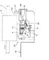
ここで、図1は、本実施形態に係るインクジェット式記録装置の外観斜視図である。なお図1では、インクジェット式記録装置の内部構成を現すために外カバーを外した状態を示している。図2は、同インクジェット式記録装置の要部平面図であって、キャッピング装置の周辺を示しており、図3は図2における要部正面図である。
【0036】
符合2で示すキャリッジは、主走査方向に延びるキャリッジガイド軸3に支持され、また、このキャリッジ2には駆動モータ5に接続された無端ベルトから構成されるタイミングベルト6の一部が取り付けられている。そして、タイミングベルト6の駆動によってキャリッジガイド軸3に沿って主走査方向に往復移動可能に構成されている。キャリッジ2の下底部、すなわち「被噴射媒体」の一例である被記録媒体Pと対向する面には記録ヘッド9が搭載され、該キャリッジ2に装着されたインクカートリッジ4からインクの供給を受けて、被記録媒体Pに向けてインク滴を吐出できるようになっている。記録ヘッド9は、圧力発生室(図示せず)とこれにつながるノズル開口(図示せず)を有しており、圧力発生室で所定圧に加圧されたインクがノズル開口から被記録媒体Pに向けて吐出されるように構成されている。なお、キャリッジ2には、ブラック、シアン、マゼンダ、イエローなど複数色のインクカートリッジ4を着脱自在に装着できるように構成されており、カラー印刷を実行可能となっている。
【0037】
符号18は印刷領域において記録ヘッド9の対向する位置に主走査方向に長く配設されたプラテンを示し、被記録媒体Pの非記録面を支える被記録媒体載置面として機能し、記録ヘッド9と被記録媒体Pとの距離を規定している。なお、被記録媒体Pは、図示しない被記録媒体搬送手段によって、キャリッジ2の主走査方向と直交する方向である副走査方向(図1の矢印方向)に所定量ずつ精密送りされるようになっている。
【0038】
また、キャリッジガイド軸3はギャップ調整手段としての既知の調整機構(プラテンギャップ調整機構)によってプラテン18に対して上下方向に変位することより離間/接近可能に構成されており、これにより記録ヘッド9とプラテン18との距離を調整できるようになっている。すなわち、当該インクジェット式記録装置1は、被記録媒体Pとして例えば、専用紙(写真用紙等)、普通紙、厚紙、ハガキ、ボード紙、CD(CD−R等)などの様々な被記録媒体に対応すべき構成されており、キャリッジ2の高さ位置[すなわち記録ヘッド9のノズル形成面19とプラテン18との距離(いわゆる、プラテンギャップ。以下、「PG」と示すときがある。)]を段階的に変位させることによって、上記した様々な被記録媒体に対して、ノズル形成面19と上記被記録媒体の記録面との間隔が略等しくなるように構成されている。
【0039】
本実施形態に係るインクジェット式記録装置1では、以下の4つのポジションを段階的に設定できるように構成されている。
第1ポジション;被記録媒体がCDなどである場合に設定される、PGが最大であるポジション。
第2ポジション;被記録媒体が厚紙など比較的厚みのある場合に設定される、PGが前記第1ポジションより小なるポジション。
第3ポジション;被記録媒体が普通紙などである場合に設定される、PGが前記第2ポジションより小なるポジション。
第4ポジション;被記録媒体が写真用紙などの専用紙である場合に設定される、PGが最小であるポジション。
【0040】
なお、各ポジションでの具体的なPG値は記録ヘッド9やインクの特性などその他の構成要素によって適宜設定可能であるが、本実施形態では、第1ポジションで5mm、第2ポジションで2.35mm、第3ポジションで1.45mm、第4ポジションで1.2mmとなるように構成されている。
【0041】
非印刷領域であるキャリッジ2のホームポジション位置(図1において装置右隅)には、インクの噴射特性維持手段として、記録ヘッド9のノズル形成面19を封止するキャッピング装置10が配置されている。このキャッピング装置10は、記録ヘッド9のノズル形成面19を封止するキャップ部材11を備えている。なお、キャップ部材11のサイズは、記録ヘッド9のノズル形成面19とほぼ等しく構成されている。
【0042】
また、キャッピング装置10の近傍には、キャップ部材11で記録ヘッド9のノズル形成面19を封止した状態で負圧を作用させる負圧発生手段としての吸引ポンプ12が設けられている。
【0043】
そして、駆動モータ5が駆動することによりキャリッジ2がホームポジション側の非印刷領域に移動すると、キャリッジ2の係合部82がスライド部材80の突起87に係合する。この係合に伴い、引張りバネ89に抗してスライド部材80がアーム81を介して上昇する。そして、スライド部材80のガイド84が案内溝85の低所から傾斜部を経て高所へ移動する。この動作により、キャップ部材11が記録ヘッド9に向けて上方に移動し、キャップ部材11で記録ヘッド9のノズル形成面8を封止できるように構成されている。
【0044】
一方、駆動モータ5の駆動により、キャリッジ2が印刷領域側に移動すると、キャリッジ2の係合部82がスライド部材80の突起87から離間する。これにより、引張りバネ89の作用によりスライド部材80がアーム81を介して下降する。その結果、スライド部材80のガイド84が高所から傾斜部を経て低所へ移動し、記録ヘッド9のキャップ部材11による封止が解除される。
【0045】
また、図3に示すようにキャップ部材11がノズル形成面19を封止した状態で、必要に応じて吸引ポンプ12によりノズルに負圧を作用させて、ノズルの目詰まりや、インク流路内の気泡混入を解消できるようになっている。すなわち、キャップ部材11が記録ヘッド9のノズル形成面19を封止した状態で、吸引口13を介して吸引ポンプ12によって負圧を作用させてインクを強制的に吸引排出させることで記録ヘッド9のクリーニングが行われる。
【0046】
このようにキャッピング装置10により記録ヘッド9のノズル形成面19を封止することによって、インクジェット式記録装置1の非使用時にノズルの乾燥や塵埃の付着を防ぐことができるとともに、前記したように吸引ポンプ12による負圧をノズルに作用させることでインクの強制的な吸引排出処理を行うことができるようになっている。
【0047】
キャッピング装置10の近傍の印刷領域側には、キャリッジ2の移動に伴って記録ヘッド9のノズル形成面19を払拭するワイピング装置20が配置されている。
【0048】
ワイピング装置20は、記録ヘッド9のノズル形成面19に摺接するワイピング部材21と、このワイピング部材21の一端を固定するホルダ29を備えている。ワイピング部材21の幅(図4におけるW)は、記録ヘッド9の幅と等しいか、またはこれ以上に大きくなるように構成されている。このような構成により、記録ヘッド9のノズル形成面19の全面に接触し、一様に摺動できるようになっている。
【0049】
ワイピング部材21を固定したホルダ29は、キャリッジ2が往復移動する主走査方向と直交する方向(図2における紙面上下方向。いわゆる副走査方向。)に水平状態を保持したまま(すなわち、高さ位置を変化させずに)移動させるワイピング移動機構(図示せず)を備え、これによりワイピング動作を行う場合にワイピング部材21を記録ヘッド9の移動経路内の所定位置に進出させ、そしてワイピング動作が終了した場合には退避させることができるように構成されている。ワイピング装置20の進退動作は、既知のワイピング移動機構によって行われ、その動力源には被記録媒体の搬送用モータ(図示せず)、または吸引ポンプ12等の駆動源を利用できる。そして、ワイピング部材21が記録ヘッド9の移動経路内に進出し、この状態でキャリッジ2が主走査方向に移動することにより記録ヘッド9のノズル形成面19を払拭するように構成されている。
【0050】
次に、図4から図8を参照しつつ本発明の特徴的な部分であるワイピング部材について説明する。
【0051】
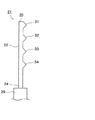
ここで、図4は一実施形態に係るワイピング部材を示す模式的な斜視図であり、図5は同ワイピング部材の模式的な側面図である。ワイピング部材21は、エラストマーなどの弾性素材から構成されており、図示の如く全体として板状に形成されている。そして、一端がホルダ29によって固定された基部22と、この基部22に形成され、上述した4つのPGポジションに対応した当接部として機能する、4つの凸部(31、32、33、34)を備えている。そして、適度に変形して記録ヘッド9のノズル形成面19に摺接するようになっている。
【0052】
すなわち、符合31で示す第1凸部は、基部22の最も自由端部(先端部)23側に設けられており、記録ヘッド9が第1ポジションに位置する場合においてノズル形成面19に摺接する当接部である。符合32で示す第2凸部は、前記第1凸部31より基端部24側に設けられており、記録ヘッド9が第2ポジションに位置する場合においてノズル形成面19に摺接する当接部である。符合33で示す第3凸部は、前記第2凸部32より基端部24側に設けられており、記録ヘッド9が第3ポジションに位置する場合においてノズル形成面19に当接する当接部である。そして、符合34で示す第4凸部は、基部22の最も基端部部(固定端部)24側に設けられており、記録ヘッド9が第4ポジションに位置する場合においてノズル形成面19に当接する当接部である。
【0053】
この実施形態においては、それぞれの凸部(31、32、33、34)は、上述した4つのPGポジションに対応するように配設されている。従って、それぞれの凸部の間隔は、第1凸部31と第2凸部32との間が1.7mm程度、第2凸部32と第3凸部33との間が0.9mm程度、第3凸部33と第4凸部34との間が0.2mm程度となるように構成されている。
【0054】
また、図6に示す如く、記録ヘッド9のノズル形成面19に摺接する凸部の形状を変えて、自由端部23側のものほど尖らせ(角をつくり)、基端部24側のものほど丸ませる(角をなくす)ように構成することが好ましい。
【0055】
このような構成により、この図6に示す実施形態に係るワイピング部材21では、凸部(31、32、33、34)による記録ヘッド9のノズル形成面19との接触面積が自由端部23側のものほど小さく、基端部24側のものほど大きくなる。
【0056】
すなわち、ワイピング部材21の凸部(31、32、33、34)によるノズル形成面19に対する押圧力は、当該ワイピング部材21を構成する弾性素材の弾性作用によって、自由端部23側のものほど小さく、基端部24側のものほど大きくなる。そして、ノズル形成面19に対する接触面積を、押圧力と同様に自由端部23側のものほど小さく、基端部24側のものほど大きく構成することにより、いずれの凸部(31、32、33、34)においても単位面積当たりの押圧力(圧力)をほぼ一定とすることができる。このため、記録ヘッド9のPGポジションに関係なく、すなわち摺接する凸部(31、32、33、34)に関係なく、ノズル形成面19を均一に払拭することが可能である。従って、PGに伴うワイピング部材21の摺接程度の違いによる払拭程度の差異が回避され、常に一定の条件で記録ヘッド9のノズル形成面19を払拭することができる。
【0057】
次に、ワイピング装置によるワイピング動作について説明する。ここで、図7はワイピング動作の説明に供する模式的な側面図である。ここでは説明の便宜上、図7(a)に示すPGが第1ポジションである場合、及び図7(b)に示すPGが第4ポジションである場合に着目して説明する。そのため、ワイピング部材21においても、第1ポジションに対応した第1凸部31、第4ポジションに対応した第4凸部34のみを示し、その他の凸部を省略して示している。そして、矢印Aに示す方向に記録ヘッド9が移動することによりワイピング動作が実行されるように構成されている。
【0058】
図7(a)は、PGが第1ポジションである場合でのワイピング動作を示す図面であり、ワイピング部材21に向かって記録ヘッド9が矢印A方向に移動することにより、ワイピング部材21が適度に変形(湾曲)し、第1凸部31が記録ヘッド9のノズル形成面19に当接する。そして、ワイピング部材21の復元力によってノズル形成面19を押圧している。
【0059】
記録ヘッド9が更に同方向に移動することによって第1凸部31がノズル形成面19に摺動しながらノズル形成面19を払拭し、付着したインク、塵埃などの異物を取り除いて清掃する。なお、第1凸部31がノズル形成面19に当接している場合には、他の凸部(34)はノズル形成面19に当接しない。
【0060】
このように基部22の最も自由端部23側に設けられた第1凸部31によって記録ヘッド9のノズル形成面19を払拭する場合には、ワイピング部材21の復元力が比較的小さいためにノズル形成面19への押圧力が小さくなってしまうが、上述したように第1凸部31はノズル形成面19との接触面積が小さくなるように、すなわち尖って形成されているので、確実にノズル形成面19を払拭できる。
【0061】
次に、図7(b)は、PGが第4ポジションである場合でのワイピング動作を示す図面であり、ワイピング部材21に向かって記録ヘッド9が矢印A方向に移動することにより、ワイピング部材21が適度に変形(湾曲)し、第4凸部34が記録ヘッド9のノズル形成面19に当接する。そして、ワイピング部材21の復元力によってノズル形成面19を押圧している。
【0062】
記録ヘッド9が更に同方向に移動することによって第4凸部34がノズル形成面19に摺動しながらノズル形成面19を払拭し、付着したインク、塵埃などの異物を取り除いて清掃する。なお、第4凸部34がノズル形成面19に当接している場合には、他の凸部(31)はノズル形成面19に当接しないように構成されている。
【0063】
このように基部22の最も基端部24側に設けられた第4凸部34によって記録ヘッド9のノズル形成面19を払拭する場合には、ワイピング部材21の復元力が比較的大きいためにノズル形成面19への押圧力が大きくなってしまうが、上述したように第4凸部34はノズル形成面19との接触面積が大きくなるように、すなわち丸ませて形成されているので、ノズル形成面19に不具合を生じさせることなく確実にこれを払拭することができる。
【0064】
すなわち、凸部(31、32、33、34)のノズル形成面19に対する接触面積を自由端部23側のものほど小さくなるように、基端部24側のものほど大きくなるように構成したことにより、図7に示す如く、凸部のノズル形成面19への当接状態が、自由端部23側のものほど点接触的となり、基端部24側のものほど面接触的となる。従って、ノズル形成面19に摺接する凸部(31、32、33、34)が異なっても単位面積当たりの押圧力(圧力)がほぼ一定となるため、PGに関係なく記録ヘッド9のノズル形成面19を均一に払拭することができる。
【0065】
ノズル形成面19に1つの凸部が当接している場合に、他の凸部が当接しないように構成するには、例えば、ワイピング部材21が変形する側(すなわち、凸部が設けられていない側)に溝などを設け、ワイピング部材21の変形の程度(折れ角度など)を調整することなどで実施できる。
【0066】
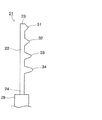
また、図8に示す実施形態の如く、基部22から凸部の頂点位置(すなわち、ノズル形成面19に当接する位置)までの高さを基端部24側のものほど高く構成することが好ましい。このように構成することにより、例えば、第4凸部34がノズル形成面19に当接した状態であっても、この第4凸部34より自由端部23側に設けられている他の凸部(31、32、33)のノズル形成面19への接触を回避することができる。すなわち、不必要な凸部のノズル形成面19への接触を防ぐことができる。
【0067】
また、記録ヘッド9の近傍には、記録ヘッド9の移動方向(矢印A方向)に沿ってノズル形成面19に向けて徐々に表面位置が変化するワイピング部材導入部40が構成されている。ここで、図9はワイピング部材導入部40の説明に供する側面図である。
【0068】
ワイピング動作時において、このワイピング部材導入部40により、その表面に沿ってワイピング部材21が徐々に変形(湾曲)し、そのワイピング動作時のプラテンギャップに対応した凸部が、記録ヘッド9のノズル形成面19に確実に摺接するように案内される。従って、ワイピング動作時のPGポジションに対応した凸部のみをノズル形成面19に確実に当接させることができる。
【0069】
また、ワイピング部材21は、このワイピング部材導入部40に沿ってノズル形成面19に案内されるので、ワイピング部材21の記録ヘッド9の側壁への衝突や、ワイピング部材21の急激な変形などの不具合を回避することができる。
【0070】
なお、本実施形態ではPGポジションが4段階ある場合について説明したが、勿論これに限定されるわけではなく、PGポジションが2段階、3段階または5段階以上のものについても、それぞれのPGポジションに対応する当接部(凸部)を備えたワイピング部材により本発明と同様の作用効果が得られる。
【0071】
また、本発明のワイピング部材は、インクジェット式記録装置などの多種類の液体噴射装置に搭載され、記録ヘッドに相当する液体噴射ヘッドのノズル形成面を払拭するワイピング部材として用いることができる。すなわち、本発明のワイピング部材は複数の当接部を有しているので、液体噴射ヘッドのノズル形成面と被噴射媒体載置面との間隔(本明細書中のプラテンギャップに相当するもの)が、上述したように1つの装置において段階的に変位するものではなく、複数の装置間(すなわち、箇々の装置の違い)において変位する場合においても、適応させることができる。つまり、装置ごとに前記間隔が異なっていたとしても、複数の当接部のうち1の当接部をその間隔に対応させてノズル形成面に当接させることにより、当該ノズル形成面に摺動してこれを払拭することができる。
【0072】
従って、本発明のワイピング部材は、インクジェット式記録装置に限られずその他の液体噴射装置においても用いることができる汎用品として使用することが可能である。
【図面の簡単な説明】
【図1】本発明の説明に供するインクジェット式記録装置の外観斜視図。
【図2】同インクジェット式記録装置の要部平面図。
【図3】同インクジェット式記録装置の要部正面図。
【図4】ワイピング部材の一実施形態を示す斜視図。
【図5】同実施形態のワイピング部材を示す側面図。
【図6】ワイピング部材の他実施形態を示す側面図。
【図7】ワイピング動作の説明に供する図面。
【図8】ワイピング部材の他実施形態を示す側面図。
【図9】ワイピング部材導入部の説明に供する図面。
【符号の説明】
1 インクジェット式記録装置、 2 キャリッジ、 3 キャリッジガイド軸、 4 インクカートリッジ、 5 駆動モータ、 6 タイミングベルト、 9 記録ヘッド、 10 キャッピング装置、 11 キャップ部材、 12 吸引ポンプ、 18 プラテン、 19 ノズル形成面、 20 ワイピング装置、 21 ワイピング部材、 22 基部、 23 自由端部(先端部)、 24 基端部(固定端部)、 29 ホルダ、 31 第1凸部、 32 第2凸部、 33 第3凸部、 34 第4凸部、 40 ワイピング部材導入部、80 スライド部材、 81 アーム、 82 係合部、 84 ガイド、 85 案内溝、 87 突起、 89 引張りバネ、 P 被記録媒体[0001]
TECHNICAL FIELD OF THE INVENTION
The present invention relates to a wiping member, a liquid ejecting apparatus, and an ink jet recording apparatus.
More specifically, the present invention relates to a liquid ejecting apparatus such as an ink jet recording apparatus which ejects (discharges) a liquid such as ink from its head and attaches (executes recording) the liquid to an ejected medium (recording medium). The present invention relates to a wiping member provided for wiping a nozzle forming surface of a head, a liquid ejecting apparatus provided with the wiping member, and an ink jet recording apparatus which is an example of the liquid ejecting apparatus.
[0002]
Note that the liquid ejecting apparatus is not limited to a recording apparatus such as a printer, a copying machine, and a facsimile that uses an ink jet recording head and discharges ink from the recording head to perform recording on a recording medium. The liquid ejecting apparatus includes a device for ejecting a liquid corresponding to the application from a liquid ejecting head corresponding to the recording head to a medium to be ejected corresponding to a recording medium, and attaching the liquid to the medium to be ejected.
[0003]
As a liquid ejecting head, in addition to the recording head, a color material ejecting head used for manufacturing a color filter such as a liquid crystal display, and an electrode material (conductive paste) used for forming an electrode such as an organic EL display and a surface emitting display (FED) are ejected. A head, a biological organic substance ejection head used for manufacturing a biochip, a sample ejection head as a precision pipette, and the like can be given.
[0004]
[Prior art]
One type of liquid ejecting apparatus that ejects liquid from a nozzle opening is an ink jet recording apparatus. This ink jet recording apparatus is mounted on a carriage that reciprocates in a main scanning direction (width direction of a recording medium) and ejects (discharges) ink toward the recording medium, and sub-scans the recording medium. A recording medium transport unit that precisely feeds the recording medium by a predetermined amount in the direction is provided, and recording (printing) is performed by moving the recording head in the main scanning direction while feeding the recording medium in the sub-scanning direction.
[0005]
The recording head according to the ink jet recording apparatus having such a configuration has a pressure generating chamber and a nozzle opening connected to the pressure generating chamber, and the ink pressurized to a predetermined pressure in the pressure generating chamber from the nozzle opening to the recording medium. It is designed to inject. For this reason, the ink ejection characteristics at the nozzle openings of the recording head greatly affect the recording accuracy. Therefore, it is necessary that the ink ejection characteristics are always kept constant.
[0006]
The ink ejection characteristics fluctuate due to the increase or solidification of the ink viscosity due to the evaporation of the ink solvent at the nozzle openings, clogging due to the increase, the adhesion of dust, the intrusion of air bubbles into the ink flow path, and the like. Can cause problems.
[0007]
Therefore, the ink jet recording apparatus is provided with a capping unit, a negative pressure generating unit, and a wiping unit as a characteristic maintaining unit for maintaining the ink ejection characteristics constant (for example, see Patent Document 1).
[0008]
The capping means seals the nozzle forming surface with a capping member when the ink jet recording apparatus is not used to isolate the nozzle forming surface from the outside, thereby avoiding drying of the ink and adhesion of dust at the nozzle openings.
[0009]
Further, when a nozzle is clogged, bubbles enter the ink flow path, or the like, a negative pressure generating means is provided for removing these. The negative pressure generating means is configured to apply a negative pressure to the nozzle in a state where the nozzle forming surface is sealed by the capping member. To eliminate. The negative pressure generating means can be normally executed by a predetermined operation when the use of the ink jet recording apparatus is not used for a long period of time and the use is restarted, or when the user recognizes that the recording accuracy has deteriorated. .
[0010]
As described above, when the ink is forcibly suctioned and discharged to eliminate clogging and bubble intrusion, the discharged ink may scatter and adhere to the nozzle forming surface. Due to this adhesion, the meniscus of the ink may be disturbed, or foreign matter such as dust may be adsorbed. In such a case, a wiping means is provided which slides on the nozzle forming surface to wipe it off. The wiping means has a wiping member made of an elastic material such as an elastomer, and a base end of the wiping member is fixed by a holder. The distal end (free end) of the wiping member is relatively moved while being in contact with the nozzle forming surface, so that foreign matter such as ink adhered to the nozzle forming surface is removed and cleaning is performed. By driving the wiping means (so-called wiping operation), not only foreign substances such as ink adhered to the nozzle forming surface are removed, but also the meniscus is uniformly adjusted, and stable printing can be performed. ing.
[0011]
With respect to problems such as leakage of wiping by the wiping member and deterioration of wiping ability, a plurality of wiping portions (convex portions) are provided so that all wiping portions are in contact with the nozzle forming surface during the wiping operation. It has been reported that the problem can be solved (for example, see Patent Document 2).
[0012]
By the way, in recent ink jet recording apparatuses, for example, in order to correspond to various recording media such as special paper (photo paper or the like), plain paper, cardboard, postcard, board paper, CD (CD-R or the like), There is a configuration including a gap adjusting unit that adjusts a gap (a so-called platen gap) between a nozzle forming surface of a recording head and a platen as a recording medium mounting surface (for example, see Patent Document 3).
[0013]
[Patent Document 1]
JP-A-11-334090
[Patent Document 2]
JP-A-10-86393
[Patent Document 3]
JP-A-2002-356036
[0014]
[Problems to be solved by the invention]
In the ink jet recording apparatus provided with such a gap adjusting means, the distance (interval) between the wiping member and the nozzle forming surface of the recording head changes due to the adjustment of the gap. The force of pressing the surface has changed. For this reason, when the platen gap is large, the pressing force of the wiping member is reduced, so that the nozzle forming surface cannot be sufficiently wiped, so that wiping remains and foreign matters may remain. On the other hand, when the platen gap is small, the pressing force of the wiping member becomes unnecessarily large, and the nozzle forming surface is defective (for example, the plating layer is peeled off the nozzle forming surface, the water repellent treatment effect is reduced). Was caused.
[0015]
SUMMARY OF THE INVENTION The present invention has been made in view of such a problem, and an object thereof is to provide a wiping member capable of wiping a nozzle forming surface corresponding to a gap between a medium receiving surface and a nozzle forming surface of a liquid ejecting head. A liquid ejecting apparatus including the wiping member, and an ink jet recording apparatus which is an example of the liquid ejecting apparatus.
[0016]
[Means for Solving the Problems]
In order to solve the above problem, an invention of a wiping member according to a first aspect of the present invention includes a liquid ejecting head that ejects a liquid from a nozzle opening toward a medium to be ejected, and an ejected liquid that is opposed to the liquid ejecting head. A medium mounting surface, a gap adjusting means for adjusting a gap between the jetted medium mounting surface and the nozzle forming surface of the liquid ejecting head in a stepwise manner, and relative movement with respect to the liquid ejecting head; A wiping member that slides on a nozzle forming surface of a liquid ejecting head, the wiping member being used in a liquid ejecting apparatus, wherein the wiping member is in a stage between the ejection target medium mounting surface and the nozzle forming surface. And a plurality of contact portions that are provided corresponding to the typical gaps and contact the nozzle forming surface.
[0017]
According to this feature, since the wiping member is provided corresponding to the stepwise gap between the ejection target medium mounting surface and the nozzle forming surface, and has a plurality of contact portions that contact the nozzle forming surface, Even when the gap (interval) between the medium-receiving surface and the nozzle forming surface is changed by the gap adjusting means, the contact portion of the wiping member corresponding to the gap surely contacts the nozzle forming surface and slides. By doing so, the nozzle forming surface can be reliably wiped. Therefore, the nozzle forming surface can be accurately wiped by the corresponding contact portion at any stage of the gap, and there is no problem such as unwiping.
[0018]
Further, according to the invention of the wiping member according to the second aspect of the present invention, in the first aspect, the plurality of abutting portions may be in contact with the nozzle forming surface as the free end side of the wiping member is closer. It is characterized in that it is configured to have a small area.
[0019]
The wiping member is made of an elastic material, is appropriately deformed in a state of sliding on the nozzle forming surface, and slides on the nozzle forming surface by using its restoring force. Becomes smaller toward the free end (distal end), and becomes larger toward the base end (fixed end). Therefore, if the free end side of the wiping member contacts the nozzle forming surface, the pressing force is too small, wiping is not performed sufficiently, and unwiping may occur. On the other hand, if the contact is made on the base end side, the pressing force is too large, and there is a possibility of causing troubles (for example, peeling of the plating layer on the nozzle forming surface, reduction of the water repellent effect, etc.).
[0020]
However, in the present invention, the plurality of abutting portions are configured such that the contact area with the nozzle forming surface becomes smaller as the one on the free end side of the wiping member becomes smaller. Even if the contact portion contacts the nozzle forming surface, it can be sufficiently wiped. On the other hand, when the gap is small, even if the contact portion on the base end side abuts on the nozzle forming surface, the above problem caused by too large pressing force due to the large contact area with the nozzle forming surface is avoided. Can be.
[0021]
That is, the pressing force on the nozzle forming surface by the contact portion of the wiping member is smaller on the free end side, and is larger on the base end side. The contact area with the nozzle forming surface is configured to be smaller on the free end side and larger on the base end side as in the case of the pressing force. Since the pressure (ie, pressure) is substantially constant, it is possible to uniformly wipe the nozzle forming surface regardless of the gap. Therefore, a difference in the degree of sliding contact of the wiping member due to the gap can be avoided, and the nozzle forming surface can always be wiped under a constant condition.
[0022]
Further, in the invention of the wiping member according to a third aspect of the present invention, in the first aspect or the second aspect, one of the plurality of abutting portions abuts on the nozzle forming surface. In the contact state, the other contact portion is configured to be in a non-contact state with the nozzle forming surface.
[0023]
According to this feature, only the abutment portion most suitable for the gap between the ejection target medium mounting surface and the nozzle formation surface of the liquid ejection head can be brought into contact with the nozzle formation surface, and this can be wiped off under optimal conditions. can do.
[0024]
Further, the invention of the wiping member according to a fourth aspect of the present invention is the wiping member according to any one of the first aspect to the third aspect, wherein one of the plurality of contact portions provided on the wiping member is provided. The one or more abutting portions are configured as convex portions.
[0025]
According to this feature, at least one of the plurality of abutting portions provided on the wiping member is configured as a convex portion, so that the abutting portion reliably contacts the nozzle forming surface of the liquid ejecting head during the wiping operation. As a result, the nozzle forming surface can be reliably wiped.
[0026]
The invention of a wiping member according to a fifth aspect of the present invention is the wiping member according to the fourth aspect, wherein the convex portion is closer to the base end of the wiping member so that the apex position is closer to the liquid jet head. , In the sliding contact direction.
[0027]
According to this feature, when one of the plurality of protrusions forming the contact portion is in the contact state with the nozzle forming surface of the liquid ejecting head, the other protrusion is set to the non-contact state. Can be maintained. That is, only the convex portion most suitable for the gap between the surface on which the medium to be ejected is placed and the nozzle forming surface of the liquid ejecting head can be brought into contact with the nozzle forming surface.
[0028]
According to a sixth aspect of the invention, a liquid ejecting apparatus includes the wiping member according to any one of the first to fifth aspects.
[0029]
According to this feature, in the liquid ejecting apparatus including the gap adjusting unit that adjusts the gap between the ejection target medium mounting surface and the nozzle forming surface of the liquid ejecting head, the wiping of the nozzle forming surface is performed under favorable conditions. The liquid can always be ejected under a constant condition.
[0030]
Further, according to the invention of the liquid ejecting apparatus according to a seventh aspect of the present invention, in the sixth aspect, the liquid ejecting head is provided near the liquid ejecting head along a relative movement direction between the liquid ejecting head and the wiping member. A wiping member introduction part whose surface position gradually changes toward the nozzle forming surface is configured.
[0031]
According to this feature, in the vicinity of the liquid ejecting head, the wiping member introduction portion is configured such that the surface position gradually changes toward the nozzle forming surface along the direction of relative movement between the liquid ejecting head and the wiping member. In addition, during the wiping operation, the wiping member is introduced to the nozzle forming surface along the wiping member introducing portion, so that only the contact portion corresponding to the gap at that time can be slidably contacted with the nozzle forming surface. Further, since the wiping member is gradually deformed (curved) along the surface position of the wiping member introduction portion and is introduced into the nozzle forming surface, unnecessary force (for example, when the wiping member (A collision force when colliding with the side wall of the ejection head, a deformation force due to sudden deformation, etc.) does not act.
[0032]
Further, an invention of a liquid ejecting apparatus according to an eighth aspect of the present invention is characterized in that the liquid ejecting apparatus according to the sixth aspect or the seventh aspect is an ink jet recording apparatus.
[0033]
The invention of a wiping member according to a ninth aspect of the present invention is directed to a liquid ejecting head that ejects liquid from a nozzle opening toward a medium to be ejected, and a medium to be ejected mounting surface opposed to the liquid ejecting head. A wiping member that slides on a nozzle forming surface of the liquid ejecting head by relatively moving with respect to the liquid ejecting head, wherein the wiping member is A plurality of contact portions are provided corresponding to a gap between the ejection target medium mounting surface and the nozzle forming surface and contact the nozzle forming surface, and one of the plurality of contact portions is in contact with the nozzle forming surface. It is characterized in that only the portion is configured to contact the nozzle forming surface.
[0034]
According to this feature, in various types of liquid ejecting apparatuses in which the gaps between the medium-receiving surface and the nozzle forming surface of the liquid ejecting head are different from each other, the gap is formed by sliding the nozzle forming surface of the liquid ejecting head provided in the liquid ejecting apparatus. It can be used as a wiping member for moving and wiping it. That is, it can be used as a general-purpose product compatible with various types of liquid ejecting apparatuses.
[0035]
BEST MODE FOR CARRYING OUT THE INVENTION
Hereinafter, a wiping member of the present invention and an ink jet recording apparatus which is an example of a liquid ejecting apparatus including the wiping member will be described with reference to the drawings.
Here, FIG. 1 is an external perspective view of the ink jet recording apparatus according to the present embodiment. FIG. 1 shows a state in which an outer cover has been removed to show the internal configuration of the ink jet recording apparatus. FIG. 2 is a plan view of a main part of the ink jet recording apparatus, showing the periphery of the capping device, and FIG. 3 is a front view of the main part in FIG.
[0036]
The carriage indicated by
[0037]
[0038]
Further, the carriage guide shaft 3 is configured to be able to be separated / approached by being displaced up and down with respect to the
[0039]
The ink
First position: a position where PG is the maximum, which is set when the recording medium is a CD or the like.
Second position: A position where PG is smaller than the first position, which is set when the recording medium is relatively thick such as thick paper.
Third position: a position where PG is smaller than the second position, which is set when the recording medium is plain paper or the like.
Fourth position: a position where the PG is the minimum, which is set when the recording medium is dedicated paper such as photo paper.
[0040]
The specific PG value at each position can be set as appropriate according to other components such as the characteristics of the
[0041]
A capping
[0042]
A
[0043]
When the
[0044]
On the other hand, when the
[0045]
In a state where the
[0046]
By sealing the
[0047]
On the printing area side near the
[0048]
The wiping
[0049]
The
[0050]
Next, the wiping member, which is a characteristic part of the present invention, will be described with reference to FIGS.
[0051]
Here, FIG. 4 is a schematic perspective view showing the wiping member according to one embodiment, and FIG. 5 is a schematic side view of the wiping member. The wiping
[0052]
That is, the first convex portion indicated by the
[0053]
In this embodiment, the respective convex portions (31, 32, 33, 34) are disposed so as to correspond to the above-described four PG positions. Therefore, the interval between the respective convex portions is approximately 1.7 mm between the first
[0054]
Further, as shown in FIG. 6, the shape of the convex portion which is in sliding contact with the
[0055]
With such a configuration, in the wiping
[0056]
That is, the pressing force on the
[0057]
Next, the wiping operation by the wiping device will be described. Here, FIG. 7 is a schematic side view for explaining the wiping operation. Here, for convenience of explanation, description will be made focusing on a case where the PG shown in FIG. 7A is the first position and a case where the PG shown in FIG. 7B is the fourth position. Therefore, also in the wiping
[0058]
FIG. 7A is a diagram illustrating the wiping operation when the PG is at the first position. When the
[0059]
As the
[0060]
When the first
[0061]
Next, FIG. 7B is a diagram illustrating the wiping operation when the PG is at the fourth position. When the
[0062]
As the
[0063]
As described above, when the
[0064]
That is, the contact area of the projections (31, 32, 33, 34) with respect to the
[0065]
In order to configure a configuration in which one convex portion is in contact with the
[0066]
Also, as in the embodiment shown in FIG. 8, it is preferable that the height from the base 22 to the apex position of the protrusion (that is, the position in contact with the nozzle forming surface 19) be higher toward the
[0067]
In the vicinity of the
[0068]
At the time of the wiping operation, the wiping
[0069]
In addition, since the wiping
[0070]
In the present embodiment, the case where the PG position has four stages has been described. However, the present invention is not limited to this case. With the wiping member having the corresponding contact portion (convex portion), the same operation and effect as the present invention can be obtained.
[0071]
Further, the wiping member of the present invention is mounted on various types of liquid ejecting apparatuses such as an ink jet recording apparatus, and can be used as a wiping member for wiping a nozzle forming surface of a liquid ejecting head corresponding to a recording head. That is, since the wiping member of the present invention has a plurality of contact portions, the distance between the nozzle forming surface of the liquid ejecting head and the surface on which the medium to be ejected is placed (corresponding to the platen gap in this specification) However, as described above, the present invention is not limited to a stepwise displacement in one device, but can be adapted to a case in which a displacement occurs between a plurality of devices (that is, a difference between each device). In other words, even if the interval differs for each device, one of the plurality of abutting portions is brought into contact with the nozzle forming surface in accordance with the interval, thereby sliding the nozzle forming surface. Then you can wipe it out.
[0072]
Therefore, the wiping member of the present invention can be used as a general-purpose product that can be used not only in the ink jet recording apparatus but also in other liquid ejecting apparatuses.
[Brief description of the drawings]
FIG. 1 is an external perspective view of an ink jet recording apparatus used for describing the present invention.
FIG. 2 is a plan view of a main part of the ink jet recording apparatus.
FIG. 3 is a front view of a main part of the ink jet recording apparatus.
FIG. 4 is a perspective view showing one embodiment of a wiping member.
FIG. 5 is a side view showing the wiping member of the embodiment.
FIG. 6 is a side view showing another embodiment of the wiping member.
FIG. 7 is a drawing for explaining a wiping operation.
FIG. 8 is a side view showing another embodiment of the wiping member.
FIG. 9 is a drawing for explaining a wiping member introduction unit;
[Explanation of symbols]
Claims (9)
この液体噴射ヘッドに対置された被噴射媒体載置面と、
前記被噴射媒体載置面と前記液体噴射ヘッドのノズル形成面とのギャップを段階的に調整するギャップ調整手段と、
前記液体噴射ヘッドに対して相対移動することにより、当該液体噴射ヘッドのノズル形成面に摺動するワイピング部材と、を備えた液体噴射装置に用いられるワイピング部材であって、
前記ワイピング部材は、前記被噴射媒体載置面と前記ノズル形成面との段階的なギャップに対応して設けられ、当該ノズル形成面に当接する複数の当接部を有していることを特徴とする、ワイピング部材。A liquid ejecting head that ejects liquid from a nozzle opening toward a medium to be ejected,
An ejection target medium placement surface opposed to the liquid ejection head,
Gap adjusting means for adjusting the gap between the jetted medium mounting surface and the nozzle forming surface of the liquid jet head in a stepwise manner;
A wiping member used for a liquid ejecting apparatus, comprising: a wiping member that slides on a nozzle forming surface of the liquid ejecting head by relatively moving with respect to the liquid ejecting head,
The wiping member is provided so as to correspond to a stepwise gap between the ejection target medium mounting surface and the nozzle forming surface, and has a plurality of contact portions that contact the nozzle forming surface. A wiping member.
この液体噴射ヘッドに対置された被噴射媒体載置面と、
前記液体噴射ヘッドに対して相対移動することにより、当該液体噴射ヘッドのノズル形成面に摺動するワイピング部材と、を備えた液体噴射装置に用いられるワイピング部材であって、
前記ワイピング部材は、前記被噴射媒体載置面と前記ノズル形成面とのギャップに対応して設けられ、当該ノズル形成面に当接する複数の当接部を有し、前記複数の当接部のうち1の当接部のみが前記ノズル形成面に当接するように構成されていることを特徴とする、ワイピング部材。A liquid ejecting head that ejects liquid from a nozzle opening toward a medium to be ejected,
An ejection target medium placement surface opposed to the liquid ejection head,
A wiping member used for a liquid ejecting apparatus, comprising: a wiping member that slides on a nozzle forming surface of the liquid ejecting head by relatively moving with respect to the liquid ejecting head,
The wiping member is provided so as to correspond to a gap between the ejection target medium mounting surface and the nozzle forming surface, has a plurality of contact portions that contact the nozzle forming surface, and includes a plurality of contact portions. The wiping member is characterized in that only one of the contact portions is configured to contact the nozzle forming surface.
Priority Applications (1)
| Application Number | Priority Date | Filing Date | Title |
|---|---|---|---|
| JP2003060687A JP4258616B2 (en) | 2003-03-06 | 2003-03-06 | Wiping member |
Applications Claiming Priority (1)
| Application Number | Priority Date | Filing Date | Title |
|---|---|---|---|
| JP2003060687A JP4258616B2 (en) | 2003-03-06 | 2003-03-06 | Wiping member |
Publications (2)
| Publication Number | Publication Date |
|---|---|
| JP2004268352A true JP2004268352A (en) | 2004-09-30 |
| JP4258616B2 JP4258616B2 (en) | 2009-04-30 |
Family
ID=33123114
Family Applications (1)
| Application Number | Title | Priority Date | Filing Date |
|---|---|---|---|
| JP2003060687A Expired - Fee Related JP4258616B2 (en) | 2003-03-06 | 2003-03-06 | Wiping member |
Country Status (1)
| Country | Link |
|---|---|
| JP (1) | JP4258616B2 (en) |
Cited By (4)
| Publication number | Priority date | Publication date | Assignee | Title |
|---|---|---|---|---|
| JP2015145095A (en) * | 2014-02-03 | 2015-08-13 | セイコーエプソン株式会社 | Liquid jet device |
| JP2016124109A (en) * | 2014-12-26 | 2016-07-11 | 京セラドキュメントソリューションズ株式会社 | Recording-head recovery system and ink jet recording device including the same |
| JP2018111238A (en) * | 2017-01-11 | 2018-07-19 | 京セラドキュメントソリューションズ株式会社 | Head cleaning mechanism and ink-jet recording device having the same |
| JP2018114666A (en) * | 2017-01-18 | 2018-07-26 | 京セラドキュメントソリューションズ株式会社 | Head cleaning mechanism and ink jet recording device including the same |
-
2003
- 2003-03-06 JP JP2003060687A patent/JP4258616B2/en not_active Expired - Fee Related
Cited By (4)
| Publication number | Priority date | Publication date | Assignee | Title |
|---|---|---|---|---|
| JP2015145095A (en) * | 2014-02-03 | 2015-08-13 | セイコーエプソン株式会社 | Liquid jet device |
| JP2016124109A (en) * | 2014-12-26 | 2016-07-11 | 京セラドキュメントソリューションズ株式会社 | Recording-head recovery system and ink jet recording device including the same |
| JP2018111238A (en) * | 2017-01-11 | 2018-07-19 | 京セラドキュメントソリューションズ株式会社 | Head cleaning mechanism and ink-jet recording device having the same |
| JP2018114666A (en) * | 2017-01-18 | 2018-07-26 | 京セラドキュメントソリューションズ株式会社 | Head cleaning mechanism and ink jet recording device including the same |
Also Published As
| Publication number | Publication date |
|---|---|
| JP4258616B2 (en) | 2009-04-30 |
Similar Documents
| Publication | Publication Date | Title |
|---|---|---|
| US9168754B2 (en) | Liquid ejection apparatus | |
| JP5493944B2 (en) | Cleaning method and fluid ejecting apparatus | |
| KR100799005B1 (en) | Liquid ejection apparatus with liquid wiper device | |
| JP3918370B2 (en) | Inkjet recording device | |
| US7758151B2 (en) | Wiper device and liquid ejection apparatus | |
| US6883897B2 (en) | Ink jet recording apparatus and cleaning unit thereof | |
| JP2005040975A (en) | Wiper for liquid ejection head and liquid ejector | |
| JP3234087B2 (en) | Ink jet recording device | |
| JP4258616B2 (en) | Wiping member | |
| US8740346B2 (en) | Liquid ejecting apparatus | |
| JP4168770B2 (en) | Liquid ejector | |
| JP2005144947A (en) | Liquid jet apparatus | |
| JP2004074514A (en) | Wiping member, liquid ejector, and inkjet recorder | |
| JP2022129724A (en) | inkjet printer | |
| JP2004299209A (en) | Liquid jetting characteristics sustaining device, liquid jetting device, and inkjet recorder | |
| JP4006587B2 (en) | Liquid ejector | |
| JP3906794B2 (en) | Liquid ejector | |
| JP2004090407A (en) | Wiping device, liquid injection device, inkjet type recording apparatus | |
| JP4411578B2 (en) | Liquid ejector | |
| JP2005040976A (en) | Wiper of liquid ejection head and liquid ejector | |
| JP4835450B2 (en) | Wiping device and fluid ejection device | |
| WO2016051825A1 (en) | Inkjet printer | |
| JP3838414B2 (en) | Inkjet recording device | |
| JP2007326351A (en) | Liquid jetting head | |
| JP2004025488A (en) | Liquid ejector |
Legal Events
| Date | Code | Title | Description |
|---|---|---|---|
| A621 | Written request for application examination |
Free format text: JAPANESE INTERMEDIATE CODE: A621 Effective date: 20051124 |
|
| A977 | Report on retrieval |
Effective date: 20081002 Free format text: JAPANESE INTERMEDIATE CODE: A971007 |
|
| A131 | Notification of reasons for refusal |
Effective date: 20081015 Free format text: JAPANESE INTERMEDIATE CODE: A131 |
|
| A521 | Written amendment |
Free format text: JAPANESE INTERMEDIATE CODE: A523 Effective date: 20081212 |
|
| TRDD | Decision of grant or rejection written | ||
| A01 | Written decision to grant a patent or to grant a registration (utility model) |
Free format text: JAPANESE INTERMEDIATE CODE: A01 Effective date: 20090114 |
|
| A01 | Written decision to grant a patent or to grant a registration (utility model) |
Free format text: JAPANESE INTERMEDIATE CODE: A01 |
|
| A61 | First payment of annual fees (during grant procedure) |
Free format text: JAPANESE INTERMEDIATE CODE: A61 Effective date: 20090127 |
|
| FPAY | Renewal fee payment (prs date is renewal date of database) |
Year of fee payment: 3 Free format text: PAYMENT UNTIL: 20120220 |
|
| R150 | Certificate of patent (=grant) or registration of utility model |
Free format text: JAPANESE INTERMEDIATE CODE: R150 |
|
| FPAY | Renewal fee payment (prs date is renewal date of database) |
Free format text: PAYMENT UNTIL: 20130220 Year of fee payment: 4 |
|
| LAPS | Cancellation because of no payment of annual fees |